


 Melbourne BG SCS Train Timetable


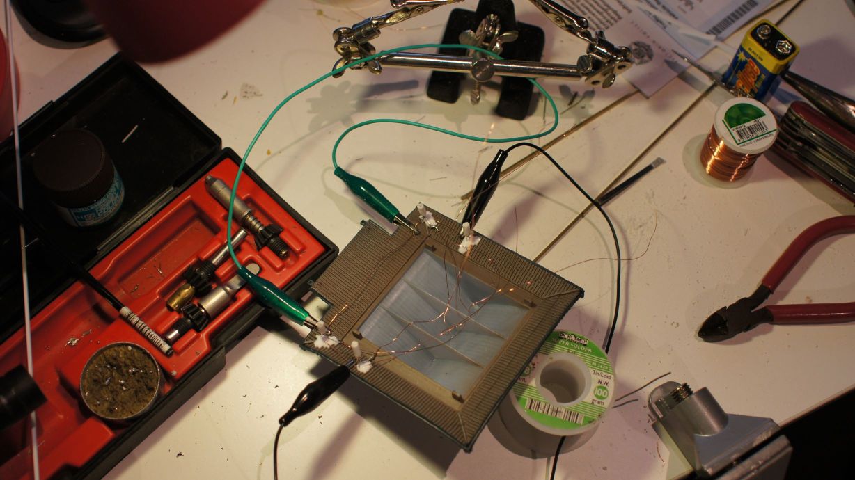
Serial Train Controller (C64+Arduino)
I'd previously attempted to use the parallel port for train control but have now switched to the Serial port for communications. I've also slapped an Arduino in between the layout and the controlling (Terminal) device. The Arduino will be programmed to understand data coming in from the Serial port, which can be fed from any device which is capable of outputting an RS-232 signal. For the example below, I'll be doing this from a Commodore 64. See this article to learn how to build a Serial Port for your C64.
Designing a communication language
Since we'll be using the RS-232 standard, we're able to define a language that any Terminal can speak to control the Arduino. This will be based on ASCII for command verbs and then raw byte data where targets and values are required. For instance, we could set throttle number 1 to 150 or point number 4 to left. Without being too tricky, 3 bytes is adequate to communicate these commands: C|T|V. If we wanted the data messages to be 'human readable' (so you can print them straight out to a file or other serial line), then we should send through 7 bytes C|TTT|VVV, where the target and value are padded out with zeroes. Fortunately, we only need these two to be 8-bit values, which is the definition of a byte. We'll simply have to convert them to ASCII if we ever want to print or display them.
Next, we'll need a command separator. I've chosen the exclamation mark '!'. Hence, when sending commands, our messages will be 4 bytes long. The recipients will need to wait data, ensure there is at least a full 4-byte message with a terminator and then start processing.
Important Note: As is described down below, I found out the hard way that not all text is equal. I've naively mentioned 'ASCII' two paragraphs above and jumped straight onto the C64, compiling strings and sending them down the wire. For some reason, although I full-well knew that I was coding in PETSCII, I neglected to think that it would actually send it down the line! Long-story-short, when the C64 sends a capital A, it actually sends a character that does not map to ASCII. Also, when it sends a lower-case A, it is actually seen in ASCII as an upper-case A!
Moral of the story? Make sure you understand what character set each device is transmitting and receiving!
Talking back to the Terminal
Although everything written above indicates that most of the communication will be one-directional; this won't always be the case! Some of the commands in the table below will actually be asking for data from the layout. This will be in the form of sensor blocks, where optical or occupation sensors will exist on the layout and be wired to binary input data. The Arduino will be hooked up to shift registers which, when daisy-chained, will be capable of 'watching' up to 64 inputs.
To get this data back to the terminal, we'll send through a message of 10 bytes. This will start with the letter S and be followed by 8 bytes of binary data indicating the state of all connected sensors. Finally a '\0' will be appended to indicate the end of the message. The Arduino wont expect a response to this; if the Terminal has failed to receive, then it can simply request the data again.
The Command Table
Now that we have our expectation of 3 data bytes and one terminator per message, we can start to define all of the commands expect to send.
| Command | Target | Data |
|---|---|---|
| T
Set Throttle |
1 or 2
The Arduino will have two separate PWM throttles. |
0 to 255
The throttles will supply 12v DC PWM. The wave-cycle will be dependent on the value from 0-255. This maps to 0-12v. Hence 128 should be roughly ~6v. |
| D
Set Direction |
1 or 2
Each throttle has it's own direction. |
F or R
Forward or Reverse. |
| P
Toggle Point |
1 to 8
8 separate points will be connected. |
L or R
We'll use ASCII here to make life easier. Left or Right can be specified. |
| S
Read Sensors |
0
We don't need to specify a block... we'll get the whole 8 bytes back regardless. |
0
No value required here. We'll send a zero for padding. |
Code for the Arduino
The Arduino will need to keep an eye on the serial port and act on commands when they appear on the channel. Data from the serial port will come in as singular bytes, so they'll need to be written into a buffer and processed once a whole message is found. In case the Arduino struggles, it'll need to be able to understand what a whole message is and discard anything that looks incomplete.
I'll skip the bits on PWM throttles, reading sensors and LED Matrices here... I'll describe all that in another article. Currently you can find individual articles on each of these topics on this site if you need the information straight away.
#include <SoftwareSerial.h>
SoftwareSerial mySerial(8,9); // RX, TX

void setup() {
	// set the data rate for the SoftwareSerial port
	mySerial.begin(2400);
}

...

void processCommand() {
	int x = 0;
	switch (serial_buff[0])	{
		case 'T':
			setThrottle(serial_buff[1], serial_buff[2]);
			break;
		case 'D':
			changeDir(serial_buff[1], serial_buff[2]);
			break;
		case 'P':
			//adjust point
			break;
		case 'S':
			//read sensors and return the data.
			break;

	}

	for (int x = 0; x < SERIAL_MAX; x++) serial_buff[x] = '\0';
	last_pos = 0;
}

...

void loop() {
	//if there's data and we've not read the end of the current message.
	if (mySerial.available() && (last_pos == 0 || last_char != '!')) {
		last_char = mySerial.read();
		serial_buff[last_pos] = last_char;
		last_pos++;
		if (last_pos > SERIAL_MAX) {
			//then we need to do something drastic
		}
		if (last_char == '!') processCommand();
	}
}
The snippet above checks if there's data and if we don't already have data. If the buffer is empty, then it'll read a character into it. If that character happens to be '\0' then it'll prevent further reading and process the message.
Controlling with a Commodore 64
cc65 has all the libraries we need to get the serial interface up and running; see more on that here. We'll use a text-based interface and control everything with the keyboard. At a later date I'll write a GEOS-based GUI.
I attempted to use the Tiny Graphics Interface libraries that cc65 provides. Unfortunately, that would've also meant writing a text renderer or graphical font library as the basic 'text out' for TGI isn't implemented on the C64. Staying with text-mode was to be easier and PETSCII has enough cool symbols to draw throttles and the like.
The screen displays the throttle, just one for now, and the direction. It also provides a clock and a schedule. The user can add and edit items in the schedule and, when in run mode, these will be executed accordingly.
void sendCommand(unsigned char c, unsigned char t, unsigned char v) {
	ser_put(c);
	ser_put(t);
	ser_put(v);
	ser_put(33);
}

...

void main() {
	...
	sendCommand('d', 1, current_direction);
	sendCommand('t', 1, current_throttle);
	...
}
I've left out most of the guff ... I'll include the full source soon. For the meantime, you'll see that I've put individual characters to the serial channel for reading at the Ardunio end. Specifically they are lower-case! You'll also note that I write 33 instead of the literal character !. The reason is, of course, that the exclamation mark in PETSCII is not the same as ASCII.
What's Next?
This works. The train happily moves back and forth using the signals sent from the C64! It's overly boring though and based on the clock. I want sensors read back to be able to trigger events... so I'll hook up the multiplexing and post again shortly.
Commodore 64: Serial Interface to Arduino
So, in my previous post, I was heading towards building an archaic circuit to control trains with the User Port. This would've worked, had I spent a lot more time and built a very complex circuit. Instead I've now chosen a new path... let's hook the C64 up to an Arduino and do most of the work there. The C64 can be the display and input/output for controlling the trains.
Interfacing both components
The C64 User Port has both a 'parallel port' with 8 i/o pins and a serial port. I initially wanted to use the parallel pins, but came to the conclusion that I'd have to write my own language on both sides and deal with the data transfer timings and clock synchronisation. Instead, it'll be easier to use industry-standard RS-232!
I suppose this is a bit of a cop-out. I wanted to build something that was dated to the level of technology that existed back when these machines were in their prime... unfortunately my electronic knowledge isn't up to scratch... so getting to a variable 12v output wasn't overly easy. It also would not have been PWM. Due to all this, including the Arduino into the mix isn't such a bad idea. Plus, everyone I'd asked for help told me to do this... even sending me links to my own blog posts :)
DTE vs. DCE
Serial plugs have a single channel, with each end having one transmit (TX) and one receive (RX) pin. Each end will send data down the cable via the TX pin and expect to receive data on the RX pin. Standard serial cables are 'straight through', meaning that the TX pin is connected to the TX pin and likewise with RX. Doesn't quite make sense, does it? How are two separate devices meant to eachother if they are both transmitting down the same singular TX wire and hearing silence on the RX?
This all becomes clear once you realise that devices fit into two categories: DTE (data terminal equipment) and DCE (data circuit-terminating equipment, also known as data communication equipment.) In the end, these two devices boil down to one being the master (the DTE) and one being the slave (the DCE.)
Of course, you can purchase 'cross-over' cables for serial connections. These are known as null-modem cables and allow you to hook two DTEs together. Say, for example, you want to transfer a file from your PC to your Amiga, or somesuch!
In my previous serial project, when I connected the IBM receipt printer to the Arduino, I needed the Arduino to be the master, and so I hacked around until I had correctly configured it as a DTE. This time around we want the Arduino to be the DCE. Due to this, be careful to follow the pinouts and wiring from the serial port to the MAX232 in the circuits below!
Note: For further reading/wiring on RS-232, there's a good article at avr Programmers and another at Advantech.
C64 Serial Port
The User Port on the C64 also has serial connections. These are TTL and so need to be brought up to the RS-232 5v standard. The MAX232 IC will do this for us quite easily. We'll also use one at the other end for the Arduino.
UPDATED (2024): The CTS and RTS wires were incorrectly ordered on the original diagram. The following diagram is now correct, but I've decided to leave the comments at the bottom of this article which state otherwise.
The circuit is derived from 8bitfiles.net. This circuit was also correct in that the pins are wired up as DTE. This means that you could use it, as-is, to also hook to a modem or any other DCE device.
The MAX232 needs few extra components. Fortunately, these extra components are identical on both ends, so buy everything in duplicate! The capacitors are all 1.0uf electrolytic. I used 1k resisters on the LEDs so as not to draw too much current from the User Port.
Arduino Serial Port
This is nearly the same circuit as the C64 end. The funniest thing happened here... if you google enough 'arduino max232' you'll just loop back around to my post, from ages ago on interfacing an IBM printer to the Arduino. Just make sure you don't use that circuit! It's DTE, we need DCE as per below! I've left out the RTS/CTS as I don't intend on using any form of handshaking in this project. It's still in the circuit above for the C64 so that you can use the port for other purposes.
As per usual, make sure you DO NOT apply 5v in the wrong direction... I did and it ruined a few caps and possibly the IC. Garbage then came through the serial port. If this ever happens, then throw out the components and start again; you'll never be able to trust them.
Also make sure that you use the 5v pin on the Arduino. AREF is NOT a valid voltage source.
Hooking it all together
Build both circuits above and give one a male and the other a female db-9 connector. The DCE device usually gets the female, so put this on the Arduino-side!
If you want to roll your own cable, then grab some grey IDC and two crimp-style plugs. Just make sure that you have pin 1 matched to pin 1. If you're splitting the cable, then paint a wire (or use a marker) to ensure that you get the orientation correct. It's really easy to confuse pin 1.
From above, you can see the pin numbering. I slid the second port all the way to the end, prior to crimping, to ensure that the numbers matched up. Using the red '#1 wire' on the cable worked wonders too.
Testing with Strike Terminal 2013 Final
Download Strike Term 2013 Final from here and then get it to your C64. I copied the D64 to my SD2IEC and loaded it up. Hit M and select User port. Hit b and switch it to 1200 Baud (or other baud, depending on what you've configured in the Arduino.)
Once ready, hit f5 and then hit enter on the default server. This'll start sending modem AT commands down the serial and they should start showing up at the other end. Either open the Arduino Serial Monitor... or edit the code to display it. I bought some 8x8 LED Matrices to render the data coming in.
There were no real caveats here... everything just worked! Press f3 to get to the terminal. Hit commodore+e for local echo and then commodore+i to 'send id'. You should now be able to type freely... everything will be sent down the wire.
At that point I only had one matrix... so the last char typed was displayed.
Writing C code to use the Serial Port
Nanoflite has written a 2400 baud User Port Serial Driver for cc65. I originally tried to use this at 1200 baud, as that's what I'd been using everywhere and heard it was the max the User Port was capable of. It turns out that this driver only supports 2400 baud! Download it and put the source somewhere.
Switch to the driver directory and compile it:
cl65 -t c64 --module -o c64-up2400.ser c64-up2400.s
Copy this to the folder that has your source file it. I slightly modified the example.
#include <stdlib.h>
#include <stdio.h>
#include <conio.h>
#include <serial.h>
#define DRIVERNAME  "c64-up2400.ser"

static const struct ser_params serialParams = {
    SER_BAUD_2400,      /* Baudrate */
    SER_BITS_8,         /* Number of data bits */
    SER_STOP_1,         /* Number of stop bits */
    SER_PAR_NONE,       /* Parity setting */
    SER_HS_NONE         /* Type of handshake to use */
};

int main (void)
{
  int xx;

  clrscr();
  puts("C64 serial ...");

  // Load driver
  ser_load_driver(DRIVERNAME);

  // Open port
  ser_open(&serialParams);

  // Enable serial
  ser_ioctl(1, NULL);

  for (xx = 0; xx < 10; xx++) {
	ser_put('C');
	ser_put('6');
	ser_put('4');
	ser_put('.');
	ser_put('.');
	ser_put('.');
  }

  return EXIT_SUCCESS;
}
Compile this:
cl65 -t c64 -O -o trainctl2 trainctl2.c
I then put it on the SD2IEC and loaded it via LOAD "0:TRAINCTL2",8 followed by a RUN.
Shit... worked... this is great! Next it's time to put a PWM throttle onto the Arduino and control it from the Commodore... I'll tinker with graphical programming in C also.
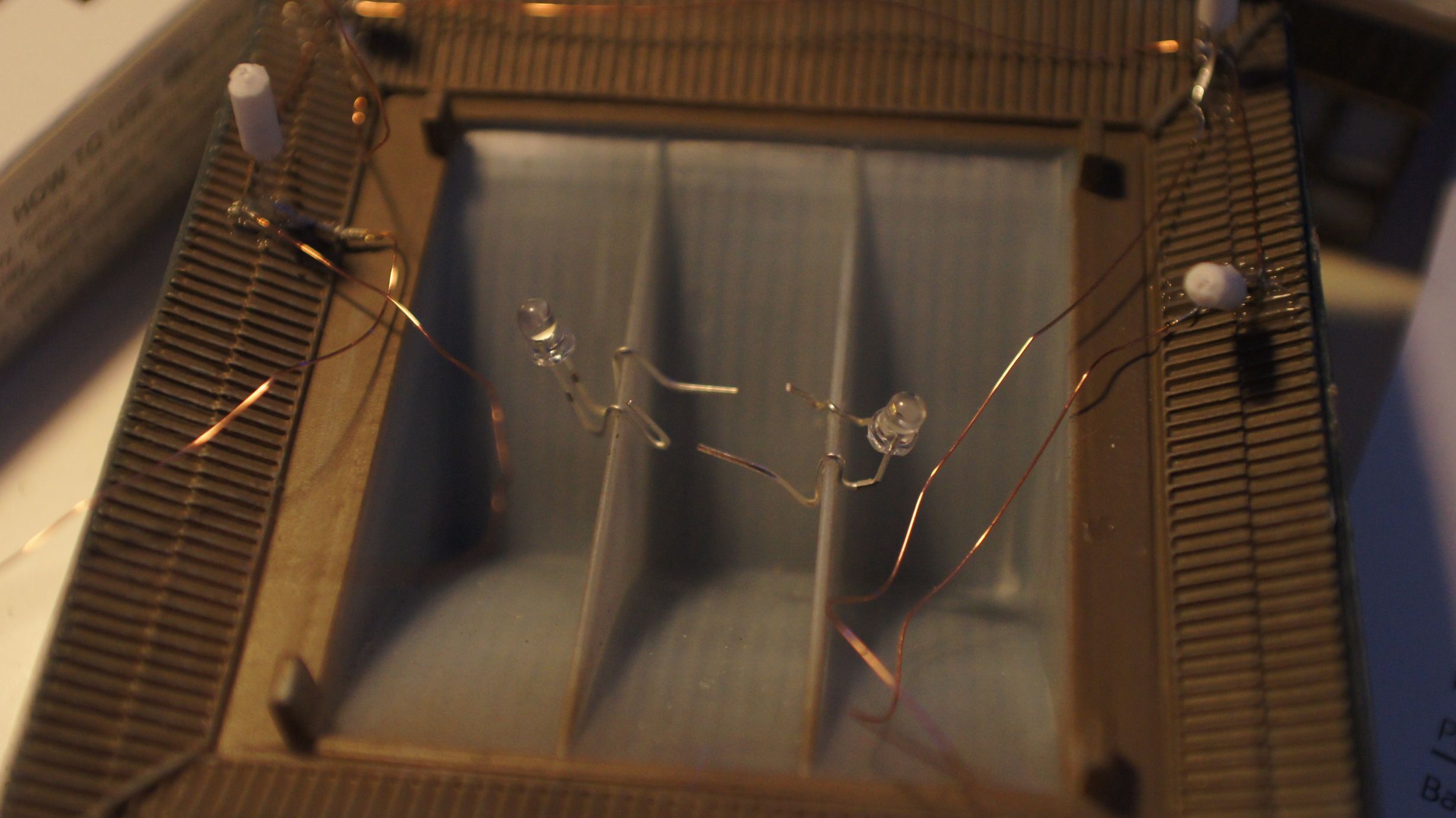
First CAN Node: LEDs and Sensors
Despite my layout being tiny, I've decided that my layout will need two nodes. One will do the sensing of trains + management of LEDs and the other will control the throttle, points and isolation. I've now finished the building and wiring of the first node. One note for below: I've used Frame IDs to differentiate the messages across the network; unique numbers are used to define the message type and each node will have filters applied to only receive nodes that are specifically for them.
Detecting Trains
Train sensing has been implemented via light sensors. I needed 24 sensors around the track and decided that multiplexing was the only way to read them all. 3x 4051 ICs came in handy and were configured as per the schematic below. You can find a better explanation on light sensor implementation in the article here.
I've simplified the code for reading the sensors as I'll ensure all of them have sufficient lighting and therefore 'stable' values. The circuit waits a second after power-up to read the initial sensor values. It then marks each one as 'active' if the value is greater than 20 'points' above the initial value. If a reading comes in lower then the initially read value then that value is lowered accordingly. I've also created a special command (frame id: 0x333) to allow a reset of all sensor values (specifically if ambient light proves a problem.)
The node sends out the sensor values and then pauses 100ms. The CAN packet with sensor data has the frame ID 0x111 and then fills three bytes with the 24 sensors states. A '1' is used for occupied and a '0' for vacant. The message will be received by any node on the network with the appropriate filters set.
Controlling LEDs
To control the LEDs I've re-used the previous MAX7219 ICs that I had lying around. There's a much more in-depth article here on how to use this chip. The MAX7219 requires three wires to the Arduino... but I'd already used up all the digital pins. Fortunately you can use the Analog pins just as easily.
As the MAX7219 can receive bytes per row to control the LEDs I simply pass through the data from the CAN bus when appropriate. It would only take one CAN message as they contain 8 bytes of data. The Frame ID for this message is 0x222. You can see that I'm being pretty wasteful with Frame IDs but, fortunately, I don't have many specific messages to send.
Completed Sensor+LED Node
So, it was soldered and wired... quite a mess really. The CAN Controller was on-board but there was no 'direct communications' interface to the PC. This meant I had to pop the chip out (atmega328) each time I wanted to change the code... tedious and dangerous!! I managed to bend pins and confuse myself every now and then. Don't do this at home!
Controller Node
I've got a third node hooked up to the computer via my trusty old Arduino Mega. This node transmits data from the CAN Bus to the PC via the standard serial-over-USB connection. A .NET application then shows the layout and allows you to interact with the LEDs and sensors accordingly. It shows the status of the sensors at any point in time and allows you to create rules in a sequence which can determine the speed and direction of the train.
The physical design of this node is simply the Arduino Mega plus the CAN schematic as seen in my previous blog post on implementing the MCP2515 controller.
  if (CAN.buffer0DataWaiting()) {
    CAN.readDATA_ff_0(&length,frame_data,&frame_id, &ext, &filter);
    Serial.write("X");
    Serial.write(frame_data[0]);
    Serial.write(frame_data[1]);
    Serial.write(frame_data[2]);
  }

  while (Serial.available() >= 9) {
    // read the incoming byte:
    b = Serial.read();
    if (b == 'L') {
      for (int i = 0; i < 8; i++) frame_data[i] = Serial.read();
      frame_id = 0x222;
      CAN.load_ff_0(8, &frame_id, frame_data, false);
    } else if (b == 'D') {
      for (int i = 0; i < 8; i++) frame_data[i] = Serial.read();
      frame_id = 0x666;
      CAN.load_ff_0(8, &frame_id, frame_data, false);
      //printBuf(frame_id, frame_data);
    } else if (b == 'R') {
      for (int i = 0; i < 8; i++) frame_data[i] = Serial.read();
      frame_id = 0x333;
      CAN.load_ff_0(8, &frame_id, frame_data, false);
    } else if (b == 'P') {
      for (int i = 0; i < 8; i++) frame_data[i] = Serial.read();
      frame_id = 0x777;
      CAN.load_ff_0(8, &frame_id, frame_data, false);
    }
  }
LED+Sensor Node Code
The sensor code consisted of an initial sensor read and then constant sensor checking. The sensors were then determined to be either 'occupied' or 'vacant' and then the data was sent. There are no 'smarts' here... the sensor data is simply hammered over the network.
The receive buffers are also checked for a Frame ID of 0x222 or 0x333. The filters are set appropriately to ensure that only these messages trigger the interrupts. The LED data is sent to the MAX7219 controller on the 0x222 message and the sensors are reset on 0x333.
void loop() {
  send_data[0] = 0;
  send_data[1] = 0;
  send_data[2] = 0;
  for (sens = 0; sens < 8; sens++) {
    setOutputBit(sens);
    sensor_read = readInput(0);
    if (sensor_read < sensor[sens]) sensor[sens] = sensor_read;
    send_data[0] |= (((20 + sensor[sens])      <= sensor_read) << sens);
    sensor_read = readInput(1);
    if (sensor_read < sensor[sens]) sensor[sens] = sensor_read;
    send_data[1] |= (((20 + sensor[sens + 8])  <= sensor_read) << sens);
    sensor_read = readInput(2);
    if (sensor_read < sensor[sens]) sensor[sens] = sensor_read;
    send_data[2] |= (((20 + sensor[sens + 16]) <= sensor_read) << sens);
  }
  frame_id = 0x111;
  CAN.load_ff_0(3, &frame_id, send_data, false);

  frame_data[0] = 0;

  data1 = CAN.buffer0DataWaiting();
  data2 = CAN.buffer1DataWaiting();

  if (data1 || data2) {
    if (data1) CAN.readDATA_ff_0(&length, frame_data, &frame_id, &ext, &filter);
    if (data2) CAN.readDATA_ff_1(&length, frame_data, &frame_id, &ext, &filter);

    if (frame_id == 0x222) {
      for (int i = 0; i < 8; i++) lcl.setRow(0, i, frame_data[i]);
    } else if (frame_id == 0x333) {
      for (sens = 0; sens < 8; sens++) {
        setOutputBit(sens);
        sensor[sens] = readInput(0);
        sensor[sens + 8] = readInput(1);
        sensor[sens + 16] = readInput(2);
      }
    }
 }
 delay(100);
}
Controller Node Code
The controller was the middle-man for translating PC code to the CAN bus and vice-versa. Sensor data from the CAN bus was converted to serial data with a leading 'X' byte. On the contrary LED commands were received from the PC with a leading 'L' byte. The following 8 bytes were sent as a single message onto the CAN bus once this character was seen.
    using System.IO.Ports;
    SerialPort _serialPort;

    private void SetupComPort() {
        _serialPort = new SerialPort("COM3", 9600, Parity.None, 8, StopBits.One);
        _serialPort.Handshake = Handshake.None;
        _serialPort.DataReceived += new SerialDataReceivedEventHandler(HandleData);
        _serialPort.Open();
    }

    private void cb_CheckedChanged(object sender, EventArgs e)
    {
        Byte[] bytesToSend = new Byte[9];
        bytesToSend[0] = (byte)'L';
        for (int i = 0; i < 8; i++) {
            for (int z = 0; z < 8; z++) bytesToSend[i+1] |= (byte)((LEDs[(i*8) + z].Checked ? 1 : 0) << z);
        }
        _serialPort.Write(bytesToSend, 0, 9);
    }

    private void UpdateSpeed()
    {
        Byte[] bytesToSend = new Byte[9];
        bytesToSend[0] = (byte)'D';
        bytesToSend[1] = (byte)(direction ? 1 : 0);
        bytesToSend[2] = (byte)hSpeed.Value;
        bytesToSend[3] = (byte)points[0]; //for loop? probably should.
        bytesToSend[4] = (byte)points[1];
        bytesToSend[5] = (byte)points[2];
        bytesToSend[6] = (byte)points[3];
        bytesToSend[7] = (byte)points[4];
        bytesToSend[8] = (byte)points[5];
        _serialPort.Write(bytesToSend, 0, 9);
        Console.WriteLine("Sent: D" + bytesToSend[1] + "-" + bytesToSend[2]);
    }
Notes learnt from hooking all this up
- CAN Filters work, but you can still see messages
On the CAN controller you can set filters to only allow specific messages through. It actually turns out that, regardless of the filter being set, if you constantly poll either buffer for a message that, if there has been a message sent, it will be available and can be received from the network. Filters simply prevent the message from triggering the 'message waiting in buffer' interrupts. So, the best bet is that you check for a message in a buffer first rather than simply constantly attempt to receive messages. Let the CAN IC tell you that a message is waiting! - You can easily spam a CAN network
Sending too many messages over the network will delay or prevent transmission of other nodes' messages. One node can send too many messages over the network preventing another from successfully getting messages into a third nodes' buffers. It's all down to how quickly the third node can receive the messages. If both receiving buffers are full then the message will fly on past and not be seen. - Inserting and removing ICs
PLEASE only do this when you need to and do this with care! Lever them out from both ends and DO NOT just use your fingers. Insert them evenly as well. It's too damn easy to destroy these delicate and expensive components.
...next will be a node to control the thottle, isolated blocks and point-servos.
Arduino + Controller Area Network (CAN)
Stolen from Wikipedia: The CAN (controller area network) bus is a vehicle bus standard designed to allow microcontrollers and devices to communicate with each other within a vehicle without a host computer. This bus standard includes it's own messaging protocol for communications between nodes on the network.
One of the most popular uses for this technology is in the automobile where the network provides a communication channel between the ECU, Transmission, airbags, braking systems, etc...
As you'll have noticed, I've recently been investigating OpenLCB which uses this technology for communications between its nodes on a model railway. The article below will show how the CAN bus can be incorporated with an Arduino to allow communications between different microcontrollers/nodes on your network.
Topography
The OpenLCB project dictates that the CAN bus implemented via their standards must not be in the form of a ring. When I initially saw the Railstars:io prototype I expected that a ring would be required; the prototype shows an 'in' and 'out' communications port. Little did I realise that, upon closer inspection, the io could act as a termination point for the CAN bus that it connects to. We therefore will implement a layout as follows on our railways...
The OpenLCB project will use standard RJ45 cables (i.e. ethernet cables) due to the requirement of twisted pair technology to guarantee data transmission.
Interfacing with the Arduino via SPI
The Serial Peripheral Interface is a communication standard used to provide communications between integrated circuits. The Arduino has an SPI library and therefore allows us to easily communicate to the CAN interface.
We'll be using the MCP2515 and MCP2551 integrated circuits to transmit/receive our data from SPI onto the CAN bus. This setup has been done before in Sparkfun's CAN-BUS Shield, the CAN-CAN, the Universal CAN Library (Universelle CAN Bibliothek) and the CANduino. The CAN-CAN Schematic and Sparkfun's schematics provide a great reference point for hooking the whole lot up. Of course, you could also just grab their shield if you don't want to build everything yourself.
Schematic
The image below should be pretty self-explanatory. See the next section for the exact pins for the SPI interface. RESET and INT can go to any digital pin.
Building, troubleshooting and talking to one's self
I built two at the same time to be able to test node-to-node communications. There was nothing overly tricky in the construction... I just chose to use relatively tight pcb prototyping boards which didn't leave much room for error. The above schematic was followed and the devices were hooked up to my Arduino(s).
I tried the loopback test from the canduino project and got random responses... the data going in was not the same as the data coming back. I started the debugging process after letting out a little sigh.
It turns out that, on all Arduinos, the SPI interface can only be used on specific pins:
| SPI Pin | Arduino Mega | Smaller Arduinos (168,328) |
|---|---|---|
| SS/CS | 53 | 10 |
| MOSI | 51 | 11 |
| MISO | 50 | 12 |
| SCK | 52 | 13 |
Note that the CAN library also then required a change as the pins in it are hard-coded to a 168/328 Arduino and wouldn't have ever worked with the Mega. You can find my fix for this down below.
I finally had responses after the pins were in the correct locations... but not the responses I wanted to see; I looked at the crystals next. My Arduinos all used 16.000MHZ crystals, but my local hobby shop only had 4mhz, 8mhz or 20mhz. This concerned me and I google'd and google'd to work out if, in the same circuit, multiple ICs could be driven off different oscillation rates. I decided that, since the 'SPI' interface had it's own 'bus rate' and the CAN bus also had it's own 'bus rate' that the crystals therefore did not affect these speeds. Also, the Arduino would dictate the speed of the SPI interface since it was the master (and slower.) I therefore bought 20mhz crystals for the MCP2515 chips, with my fingers crossed. Of course, this could have been the next issue.
Fortunately, from my previous attempts at barebones Arduinos, I had a 16mhz crystal on-hand. I swapped out the 2 capacitors and the 20mhz for the 16mhz and hooked it all up again. Nothing...
So, I then whipped out my Atmega328p 'barebones' Arduino and hooked it up to that. The SPI pins were different, as per above, so I made sure they were correct... and the CAN library from the canduino source had to be modified back to the required pins. After putting it all together I checked the serial output in the Arduino Serial Monitor and saw the correct response. The loop back test was working!
WTH... there was no reason that it should... except that maybe the SPI interface on my Mega was fried? I then, just because I hate caution and feed it to the wind all the time, swapped the 20mhz crystal and capacitors back in. It STILL WORKED! Good... I could keep the 16mhz for my other barebones Arduino.
So... with a known-working CAN node, I swapped it back onto the Mega. WTH... it worked. I now had my CAN nodes (by this time the other node built was also functioning thanks to it's guinea pig brother) talking to themselves. It was time to get them to talk to each other!
Talking in the CAN
Hah... there's an unwritten rule to not talk whilst in the toilet, but in our situation we'll make an exception. From the start I'd built the bus and was just itching to get the damn thing transmitting messages. The setup was simple: terminal blocks were used at junctions and standard dodgy speaker wire was the main network cable. 120ohm resistors were the terminators as per the standard CAN specification.
The only real issues here were the source code (or my lack of knowledge of how it worked) and the usage of crystals. Yes, they came back to haunt me... it turns out that, whilst I had the loopback going, I'd left a 16mhz on one node and a 20mhz on the other. In the source code you specify the 'CAN Bus Speed' which, of course, was configured the same on both Arduinos. The actual issue was that, when the Arduino told the CAN controller to run at bus speed '1000', the CAN nodes did this but, due to their differing crystals, their calculations of what '1000' meant were incorrect! Since one was running 4mhz faster (20mhz vs. 16mhz) it must've been communicating on the bus at a different rate and therefore confusing the hell out of the other node.
The next issue was the code... I looked over it and thought that each node would take turns in transmitting and recieving... I was wrong: you had to actually set one as the sender and one as the receiver. I configured this based on the Arduino class (by #IFDEF just as the SPI pins were configured) and then had communication! My nodes were live and functional!
RX/TX LEDs
The final step was wanting RX/TX activity LEDs. It turns out that the MCP2515 supports this, but you need to do a little configuration. If you view the datasheet at microchip you'll note that the RXnBF Pins can be configured as 'nothing', 'general outputs' or 'low on RX buffer full'. I was hoping that obe would be 'high on TX buffer', but no such luck. It actually turns out that the chip has two RX buffers and therefore two RXnBF Pins. LEDs attached to these pins will, once configured as per below, illuminate once the associated RX buffer is full. If you ever see both full then you might be losing data?
Second option: It turns out that in the MCP2515 Demo Board PDF that you can just put two LEDs on the RXCAN(1)/TXCAN(2) pins of the MCP2515.
Third option: It seems that you can also configure the INT pin to fire on TX buffer 'emptying'. You'll have to disable the pin firing on all other error situations to do this. By default, this pin is usually pulled 'high' by the MCU, so you must either disconnect that, use a resistor between the MCU and MCP2515 or just pull the pin high normally via a pullup resistor and then connect an LED in parallel with this to the INT pin. I imagine that in more complicated scenarios you'd actually want to know once the MCP2515 has generated an interrupt.
IDs: Standard or Extended?
All messages sent on the network have a 'frame id' of either (standard mode) 11-bits or (extended mode) 29-bits. It must be understood that this 'frame id' does not actually identify a node! It is simply an identifier for the actual message being transmitted. This identifier can contain any form of information you want; the bits are yours to play with.
One main use for this identifier is to record the intended recipient of the message you are sending. Depending on the amount of nodes in your network (don't forget to think of future scalability!) you can use anywhere up to 29-bits to uniquely identify them. Of course, this identifier could just be used to identify the 'class' of node and then you could put further data in the message to indicate the exact recipient. You could also go the other way and only use a portion of the identifier for the recipient code and have the rest for other uses.
The MCP2515 has in-built filtering to work on the identifier of incoming messages. If you're only using standard mode then the filters also apply to the first two bytes of the message. The filtering works inside the MCP2515 and therefore doesn't saturate your SPI link as the messages are stopped prior to being put into the RX buffer.
MCP2515 Modes
There's 5 modes that you can set the MCP2515 into. These are as follows:
| Mode | Description |
|---|---|
| Configuration | This mode allows the developer to update settings. The following settings require this mode to be set first: CNF1,CNF2,CNF3,TXRTSCTRL,MASKS,FILTERS. |
| Normal | Standard operating mode. RXM0 and RXM1 per buffer do not apply in this mode. All filters and Masks do apply. |
| Sleep | Low-power mode. SPI remains active, and the MCP2515 will wake up if there is activity on the CAN bus if the WAKIE/WAKIF interrupts are enabled. After woken, the chip will be in Listen Mode. |
| Listen | Make sure there are two or more nodes on the CAN bus. Whilst in Listen mode, the chip won't output a thing, so if another chip sends a message then the message will constantly circulate on the bus if there is no other node to 'ACK' it. Another node must be there to stop the message transmission. RXM0 and RXM1 per buffer apply in this mode and the masks/filters also do too. |
| Loopback | All messages sent are returned via the RX buffers, filtered first. No messages are sent out over the CAN. No messages are received from the CAN. |
Buffers
It needs to be noted that the MCP2515 has two receiving buffers known as Buffer 0 and Buffer 1. Messages will go to the first if it's free (and not filtered) and then the second. Filters can be set on both, but the second buffer is much more flexible with four filters.
I don't know the exact reason for the MCP2515 containing two buffers, and then why one is more flexibile than the other, but in the end it's up to the developer as to how to use them. Filters can be configured to allow specific message 'types' on each buffer. This then means that, for example, the developer could configure the second buffer to only allow emergency messages such as 'STOP THAT TRAIN' whilst the first deals with the standard communications.
Filtering CAN Messages via the MCP2515
With the base configuration, an MCP2515 controller will accept any messages sent across the network. This therefore means that your nodes need to filter each individual message coming across the bus to determine if they themselves are the intended recipient. Fortunately the MCP2515 has in-built configurable filtering to allow only messages intended for the node to be passed through its RX buffers.
The MCP2515 has 6 configurable filters with 2 masks. The first mask works in conjunction with the first two filters and applies to the first receiving buffer whereas the second mask works with the final 4 filters and works with the second receiving buffer. Filtering is enabled when any bit of a mask is '1' and disabled when the masks are completely zero'd out.
You may be wondering why both a mask and a filter are needed? As mentioned above, you may not have used the entire 'identifier' area of the sent message to indicate the recipient. Therefore, when you're checking an incoming message, you wont want to filter the entire identifier. As the identifier bits can be a '1' or '0', you need to initially specify which bits you want to check (mask) and then whether or not they are a '1' or '0' (filter).
| Node 1 ('101') | Node 2 ('110') | |
|---|---|---|
| Identifier | 10110 | 10110 |
| Mask | 00111 | 00110 |
| AND'd | 00110 | 00110 |
| Filter | 00101 | 00110 |
| Match? | False | True |
In the table above, you can see that Node 1 failed to match. The filter applied was looking for '101' (5 in decimal) but the lower 3 bits identifier (that's what the mask was looking for) was actually '110' (6 in decimal). You can see that the actual result was '110' after the mask was applied to the identifier. The second node matched as the filter is actually looking for '110'.
Now, we have to use the full registers when we apply this to the MCP2515. This means filling out 29bits of data. When in doubt, fill everything else with zeroes. Each register in the MCP2515 is 8bytes, this therefore means that you need 4 bytes per filter and 4 bytes per mask. The 6 filters and 2 masks that were mentioned above are located in the following areas:
| Mask 0 | Filter 0 | Filter 1 | Mask 1 | Filter 2 | Filter 3 | Filter 4 | Filter 5 |
|---|---|---|---|---|---|---|---|
| 0x20 | 0x00 | 0x04 | 0x24 | 0x08 | 0x10 | 0x14 | 0x18 |
| 0x21 | 0x01 | 0x05 | 0x25 | 0x09 | 0x11 | 0x15 | 0x19 |
| 0x22 | 0x02 | 0x06 | 0x26 | 0x0a | 0x12 | 0x16 | 0x1a |
| 0x23 | 0x03 | 0x07 | 0x27 | 0x0b | 0x13 | 0x17 | 0x1b |
Right, now that you know you need 4 bytes for a filter and then 4 bytes for a mask... and you know where to store them... you'll probably now need to know how to construct a mask and filter. We'll start with a mask that looks for the value 11 (decimal!) [0x0b in hex, 1011 in binary] in the standard 11-bit identifier. As you can guess, I've just provided the filter by representing the value in binary; we simply need to zero-out the bits to the left to ensure we provide the correct number. Have I provided the mask? No! Look at the truth table below if we were to use 1011 as the mask.
| Node 1 ('11011') | Node 2 ('01111') | Node 3 ('01011') | |
|---|---|---|---|
| Identifier | 11111 | 11011 | 01011 |
| Mask | 01011 | 01011 | 01011 |
| AND'd | 01011 | 01011 | 01011 |
| Filter | 01011 | 01011 | 01011 |
| Match? | True | True | True |
They all matched!?!?!? Since we were only checking the 'exact' value via the mask, we weren't actually looking to see if any of the bits around the value were set. The basic principal is that we need to know the maximum length of the value we could be looking for and then use that as the mask. For example, if you have up to '11111' (32 including '0') ids on your network, then you want to make sure that your mask is '11111' and that your filter is the exact number of the node checking if the message is theirs.
| Node 1 ('01011') | Node 2 ('01111') | Node 3 ('11011') | |
|---|---|---|---|
| Identifier | 11111 | 11011 | 01011 |
| Mask | 11111 | 11111 | 11111 |
| AND'd | 11111 | 11011 | 01011 |
| Filter | 01011 | 01011 | 01011 |
| Match? | False | False | True |
That's better! Make sure your values are correct! So, in the example below we'll use '11111' as the max value and therefore the mask. We'll then use 01011 as the value of the node we're pretending to be and we'll insert these into the correct registers (being Mask 0 and Filter 0.)
Message Acceptance Process
So, two buffers with differing filters... what happens when a message arrives? The basic idea is that a message will hit the first buffer and, if not accepted, attempt to hit the second buffer. The message is then discarded if the second buffer is also configured to not accept this message.
Note: There are also two bits (RXM0 and RXM1) in the RXBnCTRL (where n is either 0 or 1 depending on the buffer) that determine how messages are accepted. Note: My code currently has the ability to set these registers; for the life of me I cannot actually get the chip to function as per the datasheet when these registers are set. If anyone else has succeeded in using the RXM bits successfully then please leave a comment and tell how you did it!
| RXM0 | RXM0 | Description |
|---|---|---|
| 0 | 0 | [Default] Enable reception of all valid messages as determined by the appropriate acceptance filters. (See the pseudo-code below as to how the masks and filters apply.) |
| 0 | 1 | Only accept standard messages. Filters are useless if the EXIDE bit does not match with this value. For example, if you put an extended filter on buffer 0 but you disable extended messages to buffer zero with this configuration then that filter will never be used. |
| 1 | 0 | Only accept extended messages. The same rules apply that any standard filters on a buffer with this setting will not be used. |
| 1 | 1 | Receive ALL messages regardless of filters. Also recieve messages that have caused an error during transmission. The fragment of message received in the buffer prior to the error will be brought through. This mode should really only be used for debugging a CAN system. |
So, as long as the RXM bits are both set to '0', the message buffers will then process through the following procedure to accept or deny messages.
  for EACH BUFFER b: (initially 0)
    if (MASK 'b' is ZERO) { //mask 0 for buffer 0 and mask 1 for buffer 1
      Accept new message on Buffer b
    } else {
      using FILTERs 0,1 (if b equals 0) OR FILTERs 2,3,4,5 (if b equals 1)
        if (both the message and filter are 'extended') or (both the message and filter are 'standard') then
          for each '1' in MASK as 'x', does FILTER[x] equal message[x]?
            if all match then accept message
            else check next filter as this filters bits do not match the relevant message bits.
        else check next filter as this filter type does not match this message type.
      if still not accepted then TRY BUFFER 1
    }
A mask is disabled when all its bits are '0'. As soon as a bit is '1' then that mask applies to the relevant buffer. As per the section above, the bits in the filter are then checked against the relevant message bits based on what bits the mask specifies the process to check.
On the contrary, a filter is not 'disabled' when all bits are '0'; instead you have configured two filters, on the buffer related to the mask, which will only permit standard messages where the identifier is zero. If you set the mask on a buffer to anything other than 0 and then don't touch the filters, this will prevent extended messages from coming through (as both filters have '0' as the EXIDE bit) and also prevent any standard messages that do not have an identifier of zero.
In the event that you don't want to receive a specific message type, you must put a mask on both receiving buffers and then an appropriate filter to block out the specific identifier bits. On the contrary, make sure that your masks and filters are smart enough to capture all other data required for your CAN node.
If in doubt, write an 'all-seeing' debugging application to view all traffic on your bus... it'll allow you to diagnose why messages are landing where you might not want them to. As per above, setting both RXM bits to 1 will bypass your filters; this way you don't have to muck around with your own configuration too much. Just make sure you have more than two other nodes on the bus if you want another in Listen mode. Having one node on the bus, or two with one in listen mode, will mean that any message transmitted will stay perpetually on the wire. A message must be consumed by another node for it to disappear.
Storing Masks and Filters on the MCP2515
Scroll up to see the register addresses for the masks and filters. The contents of each of these registers looks as follows:
| Filter/Mask | Bit 7 | Bit 6 | Bit 5 | Bit 4 | Bit 3 | Bit 2 | Bit 1 | Bit 0 |
|---|---|---|---|---|---|---|---|---|
| Byte 0 (RX[F|M]nSIDH)* | SID10 | SID09 | SID08 | SID07 | SID06 | SID05 | SID04 | SID03 |
| Byte 1 (RX[F|M]nSIDL)* | SID02 | SID01 | SID00 | –– | EXIDE/––** | –– | EID17^ | EID16^ |
| Byte 2 (RX[F|M]nEID8)* | EID15 | EID14 | EID13 | EID12 | EID11 | EID10 | EID09 | EID08 |
| Byte 3 (RX[F|M]nEID0)* | EID07 | EID06 | EID05 | EID04 | EID03 | EID02 | EID01 | EID00 |
- *: 'n' is the filter number, i.e. RXF0SIDH is the 'Standard ID High Receive Register Filter 0'.
[F|M] means that the name is 'RXF1SIDH' for Filter 1 and 'RXM1SIDH' for Mask 1. - **: 'EXIDE': set this to '1' and this filter will only apply to Extended IDs, '0' means it will only apply to standard IDs.
This byte is unimplemented for Masks. Just leave it as zero. - ^: These two bits are not used if you are in standard mode as you only need 16 bits to check the first two bytes of data.
Have I lost you yet? Each filter and mask needs to be able to store both the Standard ID bits and the Extended ID bits. As mentioned before, if you're in standard mode then the 'lower' two bytes (i.e. bits 16 to 0 [17,18 are ignored!]) of the extended area are for matching against the first two bytes of data. You can disable this by ensuring that the associated mask has zeroes in the extended area. On the contrary, if you wanted to check the first byte in the data for a specific value then you would pass in '001111111100000000' as the extended area of the mask with the relevant extended bits set in filter.
Somewhere up above I mentioned we'd use '11111' for the mask and '01011' for the node id. We'll now store this in the registers. We'll use Mask 0 and Filter 0 for this and we'll make sure the rest are all zeroes so they don't apply. You'll note that the first register (RXM0SIDH) starts with zeros; as per above this means that the identifier could actually contain any data in this area and, since the mask is '0' for these bits, the acceptance process wont care at all! The registers will need to be set as follows:
| Register | Data | Register | Data |
|---|---|---|---|
| RXM0SIDH [0x20] | 0b00000011 | RXF0SIDH [0x00] | 0b00000001 |
| RXM0SIDL [0x21] | 0b11100000 | RXF0SIDL [0x01] | 0b01100000 |
| RXM0EID8 [0x22] | 0b00000000 | RXF0EID8 [0x02] | 0b00000000 |
| RXM0EID0 [0x23] | 0b00000000 | RXF0EID0 [0x03] | 0b00000000 |
| Note: All other Registers in the RXF/RXM space need to be zero'd out! | |||
So, as you can see above, we've put the mask 0b00000011111 in the 'standard id area' of Mask 0 and 0b00000001011 in the 'standard id area' of filter 0. Based on our logic above this will then only allow messages through that match the above requirements. Below is the code to actually do this on the Arduino.
#define MASK_0 0x20
#define FILTER_0 0x00
void CANClass::setMaskOrFilter(byte mask, byte b0, byte b1, byte b2, byte b3) {
	setMode(CONFIGURATION);
	setRegister(mask, b0);
	setRegister(mask+1, b1);
	setRegister(mask+2, b2);
	setRegister(mask+3, b3);
	setMode(NORMAL);
}

//set MASK 0 for RXB0 a mask checks all bits of the standard id.
CAN.setMaskOrFilter(MASK_0,   0b11111111, 0b11100000, 0b00000000, 0b00000000);
//set Filter 0 to 0x555. Therefore only messages with frame id: 0x555 are allowed through this buffer.
CAN.setMaskOrFilter(FILTER_0, 0b10101010, 0b10100000, 0b00000000, 0b00000000);
Note that only setting this for buffer 0 will mean that any message that doesn't match will come through on buffer 1. You'll need to also set a mask on buffer 1 to stop the messages completely. Of course, you can also only ever check buffer 0 for messages and not care if buffer 1 has anything waiting.
Filters in action: Guessing game.
Ok, who would've thought you could make microcontrollers play a game together. You know the old trick, someone else chooses a 'random' number and you get to 'randomly' guess it. Why don't we make our Arduino's play the same game?
We'll set the filter on buffer 0 to the number the receiver is thinking of. This means that the sender will only actually get a message through to the receiver if they guess the correct identifier. Both controllers will then swap roles. Just to make life easier we'll limit the range of numbers allowed, but we'll still make the guessing as 'random' as possible.
I could paste the full code here, but instead I'll just post the general idea.
| Main setup | |
|---|---|
| Set Mask of Buffer 0 to the 11-bit standard identifier Set Mask of buffer 1 to the same 11-bit id set filter 2 (first filter of buffer 1) to a specific ID for messages that aren't guesses. Set one node to RX and one to TX Initialise the random generator. |
|
| Receiver Role | Transmitter Role |
|
|
Source code (including my version of the CAN Library)
The final piece of the puzzle is always the source code. I've included the guessing game example as well. Note that my code is based off the canduino and I intend to send changes upstream where possible to make life easier for everyone.

Arduino + Thermal Printers (Sparkfun, IBM 4160-TF6)
I've always wanted to print my own receipts... devious activities come to mind; but the following usage of receipt printers is nothing sinister at all. My goal is to print out activities for trains on the layout; certain locations will have a new reporting mechanism!
I'd seen a few printers on eBay, most being USB. Serial was always to be my preferred method and I had the components on hand. I then saw the Thermal Printer at Sparkfun and decided that it'd be my first guinea pig.
Sparkfun Thermal Printer
The Sparkfun themal printer is, like most of their products, targetted at the Arduino. Thanks to this there is a wealth of information on their page on how to connect and use it. After hooking up a proper power supply (they recommend 9v @ 2Amps, so use a 7809 with a heatsink!) the printer just started spewing out whatever I threw at it.
The easiest way to use this is via the library found here: Displaying on Paper – Thermal Printer + Arduino. bildr.org is actually a really cool site full of interesting projects for the Arduino, check it out when you can!
There's a forum for discussing the above library, in which I've already posted my praises to the developer. If you need a hand then go over and ask away... they're always open to feedback and improvements to the library too!
Note that this printer uses small rolls of 58mm paper. I found a 10-pack of these at OfficeWorks (Australia) for AUD$9.95.
IBM 4610-TF6 (on Windows)
I'd finally found a dirt cheap printer on eBay that was RS-232. It was a chunky/retro IBM thermal printer and really was just a larger, more robust version of the Sparkfun thermal printer above. It didn't come with a power supply and, after purchasing, I realised that it wanted 38v! What the hell? It seems that the 'thermal' side of it uses a lot of current to burn the paper! It also wanted 3 AMPS at 38v... where the hell would I find that?
I installed the printer drivers here on a Windows XP 32-Bit machine (DOES NOT WORK WITH 64-Bit!) and provided it 12v @ 2A. The LED came on, but the printer showed up as 'offline'. All attempted connections via Hyper-Terminal showed the port as 'already open'; the printer driver would've been the cause. I uninstalled it and rebooted, but Hyper-Terminal wasn't receiving any responses after connecting successfully.
I then found a second 12v power supply and chained them together... Prior to this I'd re-installed the printer drivers and, upon the boost to 24v, the printer flicked to 'online' and the LED glowed slightly brighter. I could now also use the line-feed button on the top of the printer! I opened notepad, loaded a text file from the Arduino directory and, without thinking, hit print. The printer control panel window showed the job spooling up to 20 pages and then the printer started .... and kept going ... for an hour. It printed at a rate of about 1 line per 5 seconds.
I had no idea how to cancel it... so I had to let it go.
IBM 4610-TF6 (on the Arduino)
It was now time to make this printer talk to my Arduino Mega. I hooked it all up based on how the Sparkfun printer wiring and attempted to use the same code; nothing happened. I then used the code from Tom Taylor's Microprinter blog post. Once uploaded, I had junk coming out of the printer... It occurred to me that I probably needed a MAX232 in the middle to raise the voltages to proper RS232 levels (as per everyone elses examples!)
I hooked up the MAX232 as per the schematic below and then had a functional printer from my Arduino! Determining the actual commands to send it came next.
Fonts, spacing, etc...
Right, this gets tricky... you can either put 58mm or 80mm paper in this printer. 80mm is recommended as it has better chances of staying aligned with the paper cutter (coming out diagonally is actually an issue.) I had started with the 58mm but quickly went and bought 80mm paper (AUD$12 for 4 80x80 rolls) as I also wanted the extra printing space.
You can work out how many characters per line based on the font chosen, character spacing. It is pretty much expected that you're using 80mm paper. Font A is 10x20, Font B is 12x24 and Font C is 8x16. The Cash Receipt print line is 72 mm (2.83 inches) long. There are 576 dots per line and 203 dots per inch.
The Application Guide provides the following calculations:
- 20 CPI ⇒ 8-dot wide character + 2-dot space (Font C) ⇒ 57 characters/line
- 17 CPI ⇒ 10-dot wide character + 2-dot space (Font A) ⇒ 48 characters/line
- 15 CPI ⇒ 10-dot wide character + 3-dot space (Font A) ⇒ 44 characters/line
- 12 CPI ⇒ 12-dot wide character + 5-dot space (Font B) ⇒ 33 characters/line
Printing a Barcode
In a comment below, Jonas has asked how to print a barcode from any programming language via the serial port... Here's a list of instructions to do so:
- Set the Font (0x00 or 0x01):
0x1d 0x66 FONT 0x0a
- Set the Text Location:
- 0x00 - None
- 0x01 - Above
- 0x02 - Below
- 0x03 - Both
0x1d 0x66 POSITION 0x0a
- Set Barcode Width:
0x1d 0x68 WIDTH 0x0a
- Set Barcode Height:
0x1d 0x77 HEIGHT 0x0a
- Print a Barcode. 'CHARS' is the list of characters to print.
- 0x00 - UPC-A
- 0x01 - UPC-E
- 0x02 - JAN13 (EAN)
- 0x03 - JAN8 (EAN)
- 0x04 - CODE 39
- 0x05 - ITF
- 0x06 - CODABAR
- 0x07 - CODE 128 (c)
- 0x08 - CODE 93
- 0x09 - CODE 128 (a, b)
0x1d 0x6b BARCODE_TYPE CHARS 0x00
A 'Hello World' example of point 4 would be:
0x1d 0x6b 0x00 0x48 0x65 0x6C 0x6C 0x6F 0x20 0x57 0x6F 0x72 0x6C 0x64 0x00
IBM SureMark Thermal Printer Library for Arduino 1.0
IBM provides a great reference document for this collection of printers: ![]() Application interface specification for IBM 4610 printers. I found it to be a little hit-and-miss as to what commands are available on the TF6, but most worked well. Either way, I built the following library which provides the following functionality:
Application interface specification for IBM 4610 printers. I found it to be a little hit-and-miss as to what commands are available on the TF6, but most worked well. Either way, I built the following library which provides the following functionality:
- Text Styles: Bold, Underline, Overline, Inverted, Arbitrary Font Scaling, Double Height/Width, Rotated, Upside-down
- Barcode Printing: UPC-A, UPC-E, JAN13 (EAN), JAN8 (EAN), CODE 39, ITF, CODABAR, CODE 128 (c), CODE 93, CODE 128 (a, b)
- Image Printing from data stream, image storing to printer RAM and image printing from printer RAM
- Message storing to printer RAM and printing from printer RAM
- Beeper sounds. (Example below has 'Mary had a little lamb')
- Paper cutting, line spacing, line feeding, etc...
Other references
It turns out that, if I'd google'd more, I would've found a lot more help around the traps... here's a few locations to check out:
Controlling points/turnouts with Servos via the Arduino
I've managed to cook many Tomix Turnouts during my tinkering with the Arduino. The main issue has been applying too much current for too long. The actual switches that come with Tomix points are momentary and, internally, the circuit is only completed very quickly via a spring mechanism. The goal, of course, is to prevent the user from holding the power to the turnout magnet for too long. Unfortunately, I've managed to (via both coding and circuitry mistakes) apply too much power in the past and it takes very little time to melt the roadbase of Tomix Finetrack.
Due to all this, and the desire to use Peco Setrack, I'd decided that instead of Peco Turnout Motors (which also require large amounts of voltage) I'd use the smallest RC servos I could find. Off to eBay I went and the following arrived not so long ago.
I had no idea what servos to purchase: they seem to be rated in grams as to how much they can lift? I read in a few random locations across the web that 9g would be more than enough for switching points.
Hooking up Servos to your Arduino
This could not be easier. Arduino 1.0 already comes with the Servo Library in-built. Simply include this header and then implement the following code. The basic idea is to initialise the Servo on a specific pin (they only require one pin to be controlled) and then hook up the external power source. As per usual, it's not recommended to power too many off the USB 5v.
Mounting Servos to control Turnouts
Got some piano wire? A paperclip? Resistor legs? Any solid piece of wire/metal/rod will work to connect your turnout to a Servo. As you can see below, I've used a .55mm 'hobby wire' to connect everything up as I don't need flexibility and I want it to be robust.
You could also be very tricky and build a full interlocking frame to control multiple points at once. I bought a few 'hinges' (no idea what the real word should be) to allow the rodding to turn corners but thought it easier in the end to just install another Servo :).
Rotary Encoders allow you to switch the Turnout yourself...
Rotary Encoders are 'endless' switches which usually come with 5 pins + GND. You can continually turn them, allowing for applications where you want an inifinitely adjustable value. The pins are as follows: one side has two pins which are for the 'pushbutton', as the actual stem can be pushed into the base and provides a momentary switch. The other three on the other side are for the rotor location. The inside pin is 'common' and needs to go to ground; the outside pins are 'data' and need to be hooked into digital inputs somewhere on your Arduino.
You then simply download the rotary encoder library from PJRC, drop the main Encoder.cpp and 'utils' folder into your sketch folder and include the following source lines.
#define ENCODER_DO_NOT_USE_INTERRUPTS

#include "Encoder.h"
#include <Servo.h>

Encoder myEnc(7, 8);

Servo myservo;
long position = -999;
long srv = 0;
void setup() {
  myservo.attach(5);
}

void loop() {
  long newPos = myEnc.read();
  if (newPos != position) {
    if (newPos < position) {
      srv += 1;
      if (srv > 180) srv = 180;
    } else {
      srv -= 1;
      if (srv < 0) srv = 0;
    }
    position = newPos;
    myservo.write(srv);
  }
}
The code above will check if the rotary encoder has moved and, if it has, then check which direction and adjust the servo accordingly. Note that the servos will hum/jam if you try to turn them past any restrictions: i.e. once hooked to a turnout, the servo's movement will be limited and you should only move them as much as required... don't try and move them past the limits of the turnout. I'm quite sure that you will ruin either the servo or the turnout if you let it hum for too long past the movement of the switch.
What to do next?
Control your points based on timing? Or even based on track occupancy detection. Computerised turnout control will allow you to automate any movement over your layout. Of course, my current goal is to build a node for the OpenLCB project to control points via servos. This will need to store data, allow max/min settings per point, etc... but more as it gets built!
Persistent Data on the Arduino (EEPROM)
It's taken me a year to realise that you can actually store data at runtime on the Arduino and happily turn it off, expecting the data to still be there when you turn it on. By this, I don't mean the code you've uploaded; I mean the actual values you've created/calculated/determined whilst your code has been executing on the Arduino.
Actually, I lie... it hasn't taken a year to 'realise'... it's taken a year to actually need the ability to store information. It occurred to me, whilst looking at Don's OpenLCB railstars products, that they'd need to store everything they 'learn' as you set them up with controller nodes. All of my previous projects would've forgotten all settings once you disconnect the power!
Memory Types on the Arduino
After a little research, it turns out that Arduinos have three types of memory areas. These would be the flash, EEPROM and SRAM. The former is the location that all 'sketches' and other compiled program code go, therefore being the largest area. The EEPROM is, depending on your chip, an area around 1k to 4k in size for storing data to be persisted. Finally the SRAM is the 'running' area where data is stored during runtime of your code.
| Memory Type | ATMega168 | ATMega328P | ATmega1280 | ATmega2560 |
|---|---|---|---|---|
| Flash | 16k | 32k | 128k | 256k |
| SRAM | 1k | 2k | 8k | 8k |
| EEPROM | 512 bytes | 1k | 4k | 4k |
So, as you can see, the more you pay for the microprocessor, the more space you get to play with. I have used the Arduino Mega 1280 for a while and had never used the space available in the EEPROM... what a waste. Now I'm tinkering with the Atmega328P and, as it shows, there's a lot less space available to play with. Fortunately, depending on how frugal you are with data storage, there's more than enough for creating our OpenLCB nodes.
Working with the EEPROM
Arduino 1.0 (and all previous versions) include the EEPROM Library. This library includes two calls, being read() and write(). For the Atmega328P, I'm able to store a byte in 1024 areas. This expands to 4096 areas for the Mega.
By the way, for time-critical apps, an EEPROM write takes 3.3 ms to complete.
NOTE: As the Arduino page warns, EEPROMs are only good for 100000 writes! Please only write/update your EEPROM areas sparingly and when absolutely required.
Efficient storage of Bits/Bytes
Depending on your requirements, you may want to be more efficient in the way you store certain values. We'll start with booleans: if you're lazy and wont need to store over 1024 booleans on an Atmega328p then you can simply check the boolean and store a '1' or '0' in any of the 1024 areas. Of course, if you need more, then you'd want to efficiently use the 8 bits per byte that you have available. As each of those 8 bits can be a '1' or a '0', you can then actually store 8 booleans in each byte. It's simply a matter of 'or'ing 8 booleans together and left-shifting to ensure you set the correct bit.
byte setBit(store, bit) { //bit 1 is right-most
      store |= (1 << (bit - 1)); //set bit 5 to '1'.
}

byte clearBit(store, bit) {
      store &= !(1 << (bit - 1));
}

bool getBit(store, bit) {
      byte b = (1 << (bit - 1));
      return (store & b);
}
Arduino has a good bit of information on BitMasks and BitMath for those interested.
Using PROGMEM to store 'known' data
So, as previously mentioned, the Flash area has the most space available. The Arduino comes with the PROGMEM library for storing variables in this area. Note that you cannot easily write to this at run-time (I haven't dug far enough to work out if you really can) ... the goal is to just store large data in the flash and use it from there at runtime rather than copying to your limited SRAM first.
Firstly, you need to select from a datatype below:
| Data Type | Description |
|---|---|
| prog_char | a signed char (1 byte) -127 to 128 |
| prog_uchar | an unsigned char (1 byte) 0 to 255 |
| prog_int16_t | a signed int (2 bytes) -32,767 to 32,768 |
| prog_uint16_t | an unsigned int (2 bytes) 0 to 65,535 |
| prog_int32_t | a signed long (4 bytes) -2,147,483,648 to * 2,147,483,647. |
| prog_uint32_t | an unsigned long (4 bytes) 0 to 4,294,967,295 |
Now, declare it in the PROGMEM 'space'. It seems that the Arduino devs recommended it to be stored as an array as you'd usually only use this space for large amount of data.
I've chosen the prog_uint16_t (note that this var size is a 'word'), the code below stores two of these values and then uses them during execution.
#includePROGMEM prog_uint16_t myValues[] = { 123, 456 }; int k; //counter? don't quite know what for. int readValue1, readValue2; void setup() { k = 0; //read the first word. readValue1 = pgm_read_word_near(charSet + k); k = 1; readValue2 = pgm_read_word_near(charSet + k); } void loop() { //now you should probably do something with these values... }
And that's it.. I hope this helps some of you to limit your SRAM requirements and also to store data for users each time your device is switched off!
Building an Arduino from scratch
OK, OpenLCB is the new cool... to make 'nodes' for it, we need a skeleton Arduino to build from. This article will define how to go about this. The goal in the end is to have a prototype that can, via the Arduino IDE, have a sketch uploaded to do as you wish.
References
Firstly, a list of random links for random information on building your own Arduino:
- Arduino has a page on this: Standalone Assembly. Note that the diagram is WRONG and this schematic is not recommended.
- TheTransistor has their Minimalist Arduino Article which is perfect. This uses USB.
- Praveendb’s Weblog has a post titled Interface the Atmega 16/32 with the PC which shows how to connect the Atmega via a MAX232 Serial (NOT USB)
- There's a post at NKC Electronics Tutorials detailing how to assemble a 'Freeduino' V2.0 [MAX232] and then the 'Freeduino' v1.0 [Basic Serial Interface].
Serial or USB?
I know the DB-9 Serial Port is archaic... needs an Interrupt Request (IRQ) assigned to it etc, etc... but there's something nostalgic about plugging in a chunky cable instead of a new USB-B connector. It's also cheaper and easier to use parts on hand and I had a few MAX232s sitting around.
To use USB you'll need an FTDI chip to convert the USB signal from your PC to the TTL protocol of which the Arduino understands. Note that there are also FTDI chips which convert USB to RS232, the serial protocol that allows devices (specifically your old dial-up modems) to communicate over serial cables. You don't want one of these as you'd then have to convert the RS232 again to TTL.
Which Microcontroller?
Good question! Your choice of microcontroller comes down to size and quantity of digital/analogue inputs and outputs. I decided on the Atmega328P as it has enough IO lines for what I need on each OpenLCB node; I'll produce more node types and have them specialise rather than one node that does everything from one board. They're cheap on eBay and they are very similar to the MCU used in the Arduino Duemilanove (5 analogue and ~13 digital IOs.)
Schematic
You'll find schematics all over the web, although none seem to agree on what components are the exact bare-minimum for an Arduino... it actually makes it quite difficult to know exactly what you need. Below is a solid basis to start your Arduino-based invention, containing everything required to program over the serial port.
Building the prototype
There was not much out of the ordinary on the breadboarding of this project. It's actually quite simple and the standard rules of check, check and double-check your wire placement, IC pin numbers, etc... as you go is imperative. The serial cable connection on this project, due to the cable being rigid, can cause issues of dragging the board around. I'd recommend to seat connection and cable first and secure everything to your workbench... You'll then prevent your breadboard from upending when the serial cable chooses to move around.
Programming from the IDE
The MCU chosen is the Atmega328P and, as mentioned, it's closest match is the "Arduino Duemilanove w/ Atmega328". Once everything was connected I attempted to flash using this board, selected in the Arduino GUI, but it didn't work straight away. The initial error was that the chip device ID didn't match. It turns out that the Atmega328 has as a different code to the Atmega328P (something to do with Pico Power.) I had to hack the 'avrdude.conf' file buried in the arduino folder and then it just worked.
Before I knew it I had the servo library in and a mini servo from eBay controlling a Peco point on my layout.
Re-programming an Atmega MCU
I accidentally learnt how to do this... At one point I'd put the MCU in the wrong way around and expected that I'd killed it. The circuit then failed to work after numerous attempts with the TX and/or RX lights constantly lit. It wouldn't accept sketches and I therefore thought the best bet was to re-flash the bootloader + program.
It turns out that my Arduino Mega can be used as an In-Serial Programmer and so I set this up. This can be selected via the "Arduino ISP" option in the "Programmer" menu under the new Arduino 1.0 software.
(Note that the capacitor from +5v to RESET is a 100n non-polarised.)
After the re-flash and a reconfigure of the MAX232 in/outs (the schematic above is the final version that now works perfectly) it all just worked again... for one of the MCUs anyway. The second simply refused to receive sketches; the RX light would not turn off. I took this as a fundamental failure in the chip (I blame my bread-boarding skills) and therefore tried something sneaky: I copied the entire code off the MCU that worked and flashed it to the 'broken' one with avrdude and it's associated avrdude-GUI [direct download link]. It turns out this worked... the chip now did what the previous one did... but in the MAX232 breadboard it still would not accept a new sketch from the Arduino GUI. I attempted to find other methods to 'completely erase/reset' an Atmega, but I couldn't get it to work and so just accepted it's fate of having to copy it's brother.
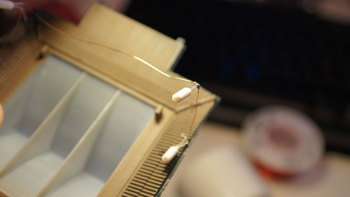
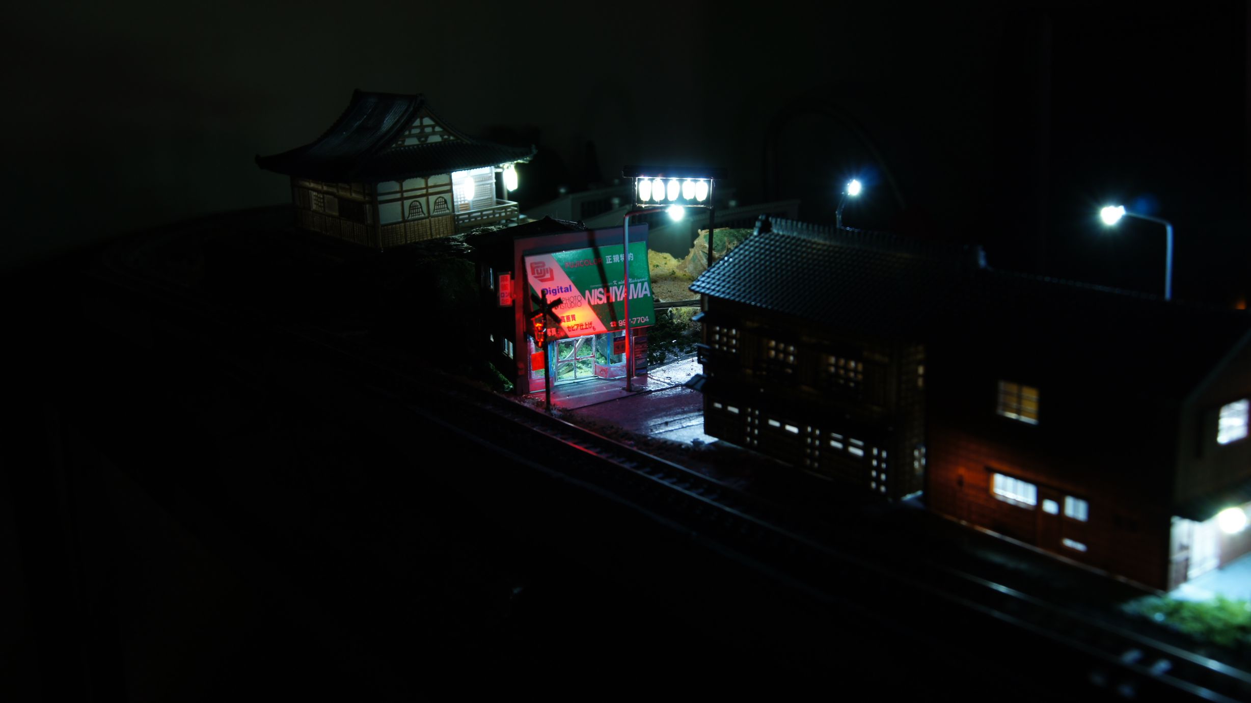
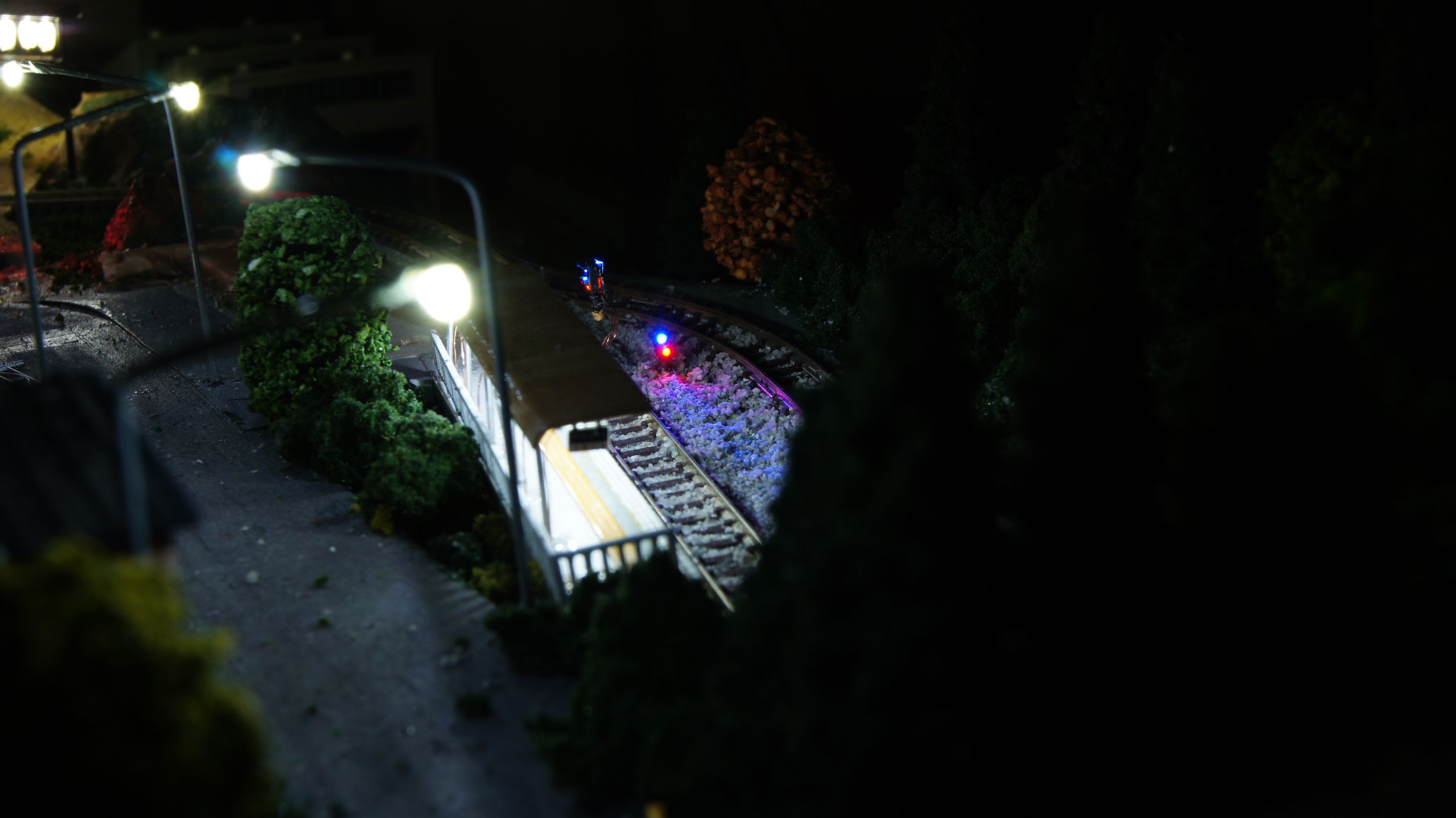
Lighting a Japanese Temple

I'd decided it was time to light the temple after building the Torii for the entrance. This temple was the Tomytec Japanese Temple A (Main Building) and is still available for purchase from most Japanese online hobby retailers.
I've slapped LEDs in buildings before, but this time I also wanted to add lanterns to the front of the shop. I'd made the lanterns before, as in my previous attempts of creating the Torii, but I was to make a few changes this time as I wasn't totally impressed with the previous outcome.
Creating the lanterns
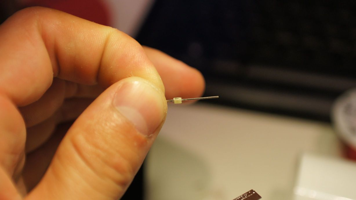
There was a slight change this time to creating the lanterns... instead of cutting them and sliding them over the LEDs, I shaved them down to fit and inserted them into the center of the tubing. This all worked well, but you must be careful when shaving down the LEDs as you can destroy them quite easily. To shave the LEDs, I held them in pliers in one hand and filed away with my pocket knife. It was pretty obvious to feel when you were no longer filing away at plastic and, unfortunately, this was usually the demise of the LED.

Mounting the lanterns
I used the same copper winding wire that I always do and bent it into a rectangular shape to fit the roof of the temple. I then started soldering the lanterns in place.
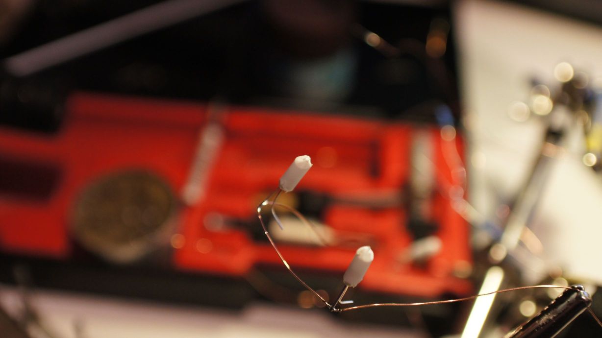
I then pulled out the trusty Selleys Aquadere and, using random aligator clips found on the bench, glued the lanterns in place.
I also put two standard 3mm white LEDs in the center of the ceiling for building lights.
The finished product
After the glue had dried, I tested all the LEDs and found that I'd broken the front-left lantern. This was 24hours after starting the project and frustrating. I quickly removed it from the temple and filed another LED down. I left it dry again, overnight, after testing, gluing and testing again.
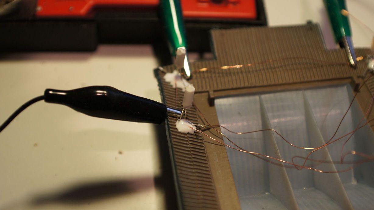
Finally, yesterday, I was able to hook it up to my Arduino LED Controller. It worked perfectly and I took the opportunity to test my night-time photography skills.


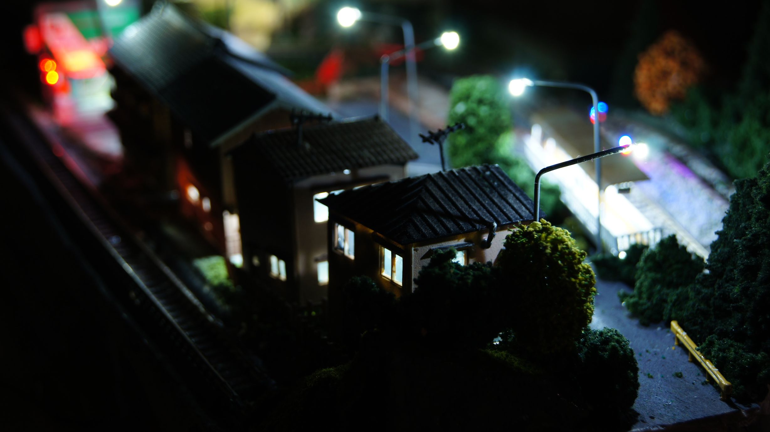
Now to settle the landscape around it.
An attempt to simulate Acceleration and Braking
In my previous post, I'd managed to get my Densha-De-Go Dreamcast controller hooked up to my Arduino Mega. Now although this now meant that I had a great way to control my model railroad, it also meant I had to work out how to code a throttle and a brake lever.
The rules
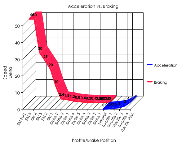
After a few hours of plotting, I had decided on the following system. It involves a 6-position throttle and an 11-position brake. Each 'position' is to have a 'max speed' and 'speed adjust' associated with it.
Notes
- It is to be assumed that if the brake is on, the throttle is automatically disabled
- MAX is 255 on the PWM Throttle (or max voltage from supply)
- At Throttle 0, the train is neither powering nor braking; we will simply slowly decrement the speed
- There is no feedback to know how fast the train is currently travelling
- There are multiple emergency brake points on the throttle, but we don't care about them.
The next table shows my acceleration and braking deltas. This will be a simple addition and subtraction on the current speed.
| Lever position | Max Speed | Speed Adjustment |
|---|---|---|
| Emergency Full | Instant Stop | |
| Emergency 5 | -50 | |
| Emergency 4 | -30 | |
| Emergency 3 | -25 | |
| Emergency 2 | -20 | |
| Emergency 1 | -10 | |
| Brake 9 | -2.4 | |
| Brake 8 | -1.8 | |
| Brake 7 | -1.2 | |
| Brake 6 | -0.8 | |
| Brake 5 | -0.4 | |
| Brake 4 | -0.2 | |
| Brake 3 | -0.1 | |
| Brake 2 | -0.05 | |
| Brake 1 | -0.025 | |
| Throttle 0 | 0 | 0.00 |
| Throttle 1 | 55 | +0.25 |
| Throttle 2 | 75 | +0.5 |
| Throttle 3 | 90 | +1 |
| Throttle 4 | 100 | +1.75 |
| Throttle 5 | 120 | +2.5 |
And now a better way to represent it.
The code
The table above translates to code quite easily... the goal is to have the lever position values coded into an array and then just select the correct entry. Once determined, the main code loop can then determine how to adjust the current voltage output to the rails.
const int throttle_positions = 21;
const int throttle_absolute_maximum_speed = 255;
const int throttle_minimum_speed = 20;
int current_throttle_position = -1; // 0 is EM FULL. Lever must be moved to EM FULL to begin.
float current_speed = 0;
float target_speed = 0;
int throttle_max_speed[throttle_positions] =  {
	0,0,0,0,0,0,0,0,0,0,0,0,0,0,0, //brake positions and Throttle 0
	0, 55, 75, 90, 100, 120
};
float throttle_delta[throttle_positions] = 	{
	0.025, 0.05, 0.1, 0.2, 0.4, 0.8, 1.2, 1.8, 2.4, 10, 20, 25, 30, 50, 9999, //brake
	0.00 /*coast*/, 0.25, 0.5, 1, 1.75, 2.5
};
We then need to determine the current throttle position. We will make it that, at the start of code execution, the train should not move until the throttle has been reset to EM Full and the throttle at '0'.
#define BRAKE_MASK 0xf0
#define BRAKE_SHIFT 4
#define ACCEL_MASK 0x07
void read_throttle_position() {
	int accel = packet.data[6] & ACCEL_MASK;
	int brake = (int)((packet.data[7] & BRAKE_MASK) >> BRAKE_SHIFT);

	if (current_throttle_position == -1) {
		//check that we have EM FULL and Neutral
		if (brake  == 15 && accel  == 1) {
			//set the initial '0' (EM FULL) position.
			current_throttle_position = 0;
			lcd.clear();
		}
	} else {
		if (brake != 1) { //1 == "BRAKE 1", if it's higher, we're braking.
			if (brake > 0) current_throttle_position = brake;
		} else { //BRAKE == 1 and then we check the throttle
			//we're accelerating.
			if ((accel + 15) < 22) current_throttle_position = accel + 15;
		}
	}
}
And now the main game loop needs to determine the current lever locations and then choose the appropriate action:
void update_speed() {
		digitalWrite(13, LOW);
	//make sure we are allowed to go.
	if (current_throttle_position >= 0) {
		if (current_speed > throttle_max_speed[current_throttle_position - 1]) {
			current_speed -= throttle_delta[current_throttle_position - 1];

			//braking... don't go negative.
			if (current_speed < throttle_minimum_speed)
				current_speed = 0;

		} else if (current_speed < throttle_max_speed[current_throttle_position - 1]) {

			//accelerating, so start from minimum speed.
			if (current_speed < throttle_minimum_speed)
				current_speed = throttle_minimum_speed;

			current_speed += throttle_delta[current_throttle_position - 1];

			//don't go faster than current throttle max setting.
			if (current_speed > throttle_max_speed[current_throttle_position - 1])
				current_speed = throttle_max_speed[current_throttle_position - 1];
		}

		//set light if we have met max speed for throttle.
		if (current_speed == throttle_max_speed[current_throttle_position - 1])
			digitalWrite(13, HIGH);

		//output speed to railway.
		analogWrite(7, current_speed);
	} else {
		//flash the LED to alert user to reset controls.
		delay(200); //delay a little to flash the LED
		digitalWrite(13, HIGH);
		delay(200);
	}
}
There's also some code in the main loop to update the 16x2 LCD I've hooked up. Since we need to reset the controller when we start, it'll tell you to do so and afterwards will tell you the current throttle/brake position, current speed and speed delta.
 Download the source code here.
Note that this does not include the full arduino-maple code. Download that here. You will also need the LiquidCrystal library from the Arduino site.
Action shots
Shown is the controller in certain positions. Note that the 'Throttle' positions may show a negative speed delta; this just means that they are no longer accelerating.
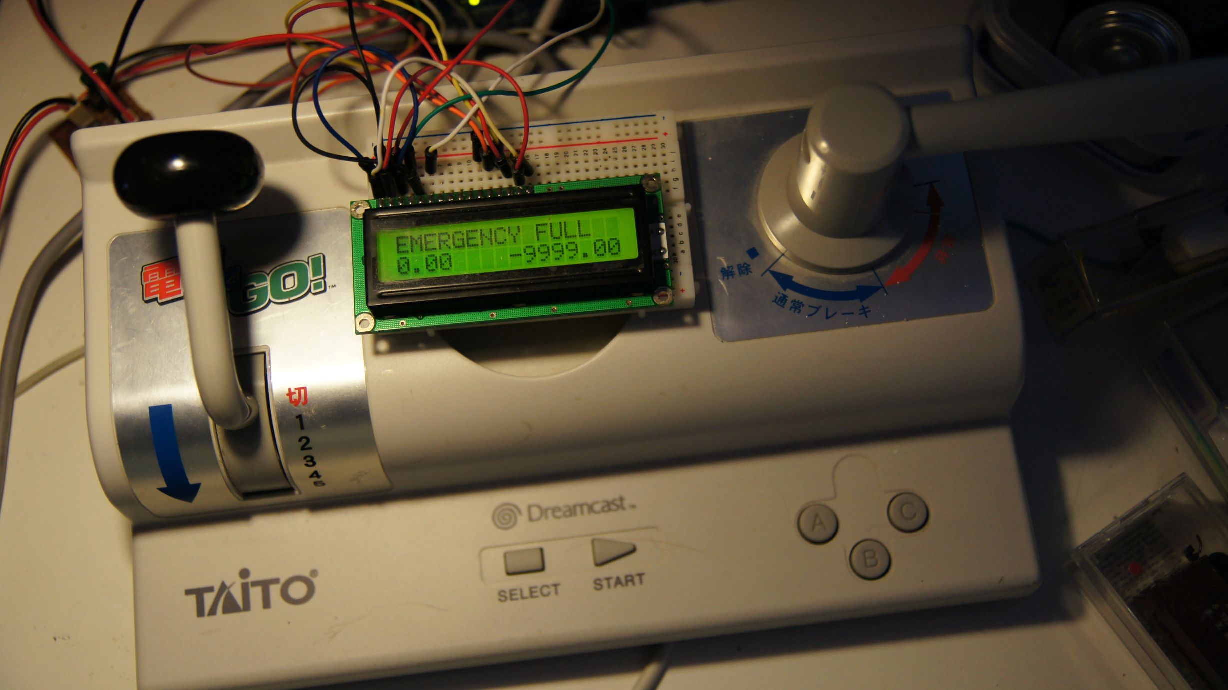
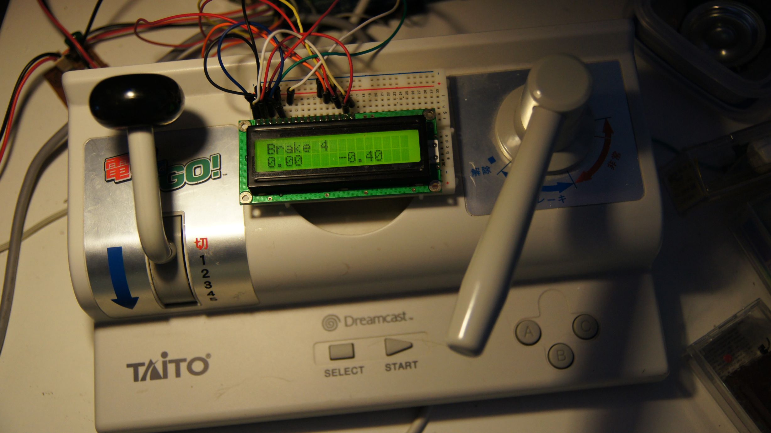
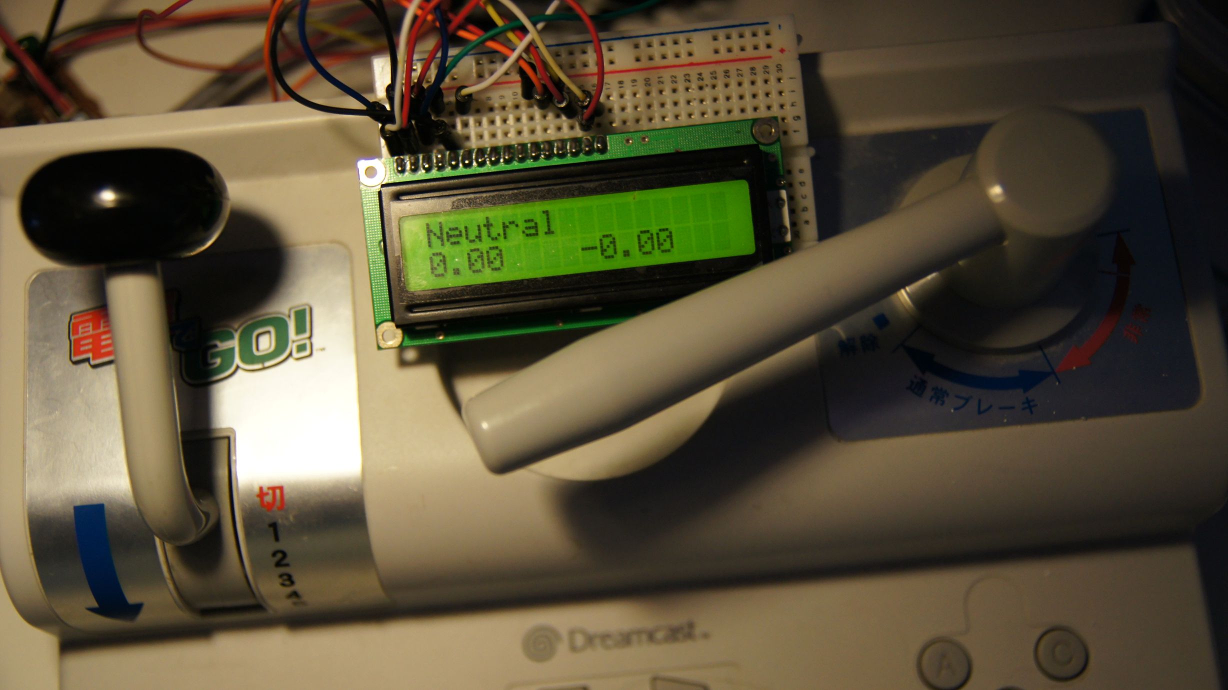
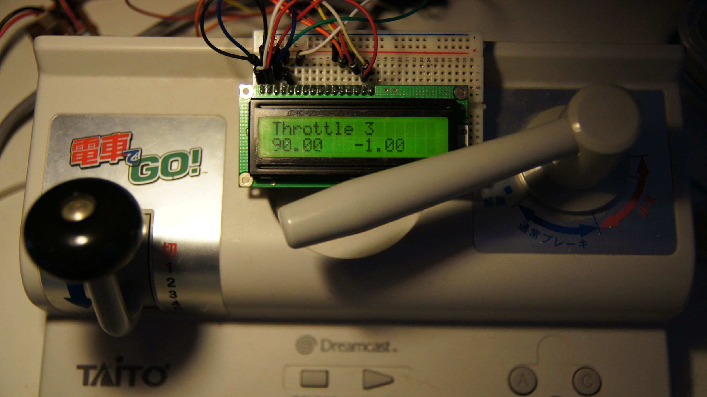
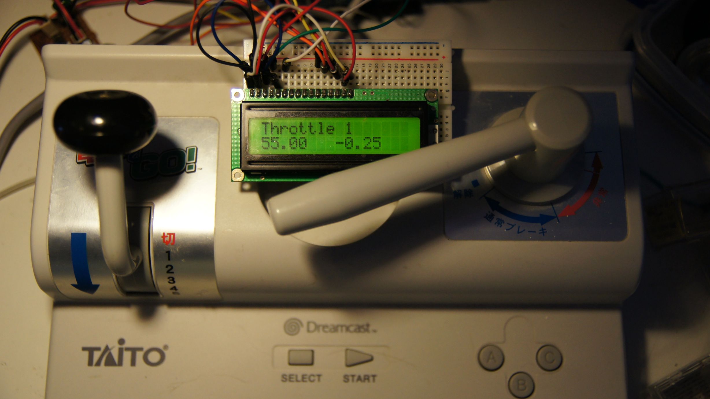
Random Photos
Search
Tags
Links - Click for details
- Abandoned Rails (Japan)
- AIRLINE (Shinkansen Photography)
- Akihabara Station
- annexpressのブログ
- Australian Model Railway Magazine
- DCC普及協会ホームページ (Japanese DCC)
- Dead Section (Japanese Track Diagrams)
- Delicious Things (Japanese N Scale DCC)
- Densha Wotorou
- Digital Direct for Windows (DCC Server)
- Don's Dream World – AMAZING N Scale Japanese Layout
- Hatena::Diary
- Japanese N-Scale Modeling Forum
- JR Chiisai
- Kaz-T's blog レインボーライン (Rainbow Line)
- LED Resitance Calculator
- Masioka
- Poppondetta Blog
- RailFan Magazine, Japan
- Railmind
- Railway Travelers' Room
- Serenity Valley
- Shashinka Ichiban
- Shuzuku
- Sumida Crossing
- The next station is…
- Tomix N Gauge Track and Japanese N Gauge Trains
- TT Forums (Transport Tycoon Deluxe)
- 名鉄尾西線の貨物列車 (Nagoya: Meitetsu Freight)
- 日本型Nゲージ DCC改造例のご紹介 (Okiraku DCC)
- 泰 茅 轍 道 (Taichi Railway)
- 箱庭登山鉄道製作記 (Hakone-Tozan Layout Blog)
Archive
- July 2026
- May 2026
- April 2026
- March 2026
- February 2026
- January 2026
- November 2025
- October 2025
- September 2025
- August 2025
- July 2025
- June 2025
- February 2025
- January 2025
- November 2024
- September 2024
- August 2024
- July 2024
- June 2024
- May 2024
- April 2024
- March 2024
- February 2024
- December 2023
- October 2023
- September 2023
- August 2023
- July 2023
- June 2023
- May 2023
- April 2023
- March 2023
- December 2022
- November 2022
- October 2022
- April 2022
- March 2022
- February 2022
- January 2022
- December 2021
- November 2021
- September 2021
- August 2021
- July 2021
- May 2021
- March 2021
- February 2021
- January 2021
- October 2020
- September 2020
- August 2020
- July 2020
- June 2020
- May 2020
- April 2020
- March 2020
- January 2020
- December 2019
- November 2019
- October 2019
- September 2019
- August 2019
- July 2019
- June 2019
- April 2019
- March 2019
- February 2019
- January 2019
- December 2018
- November 2018
- October 2018
- September 2018
- August 2018
- July 2018
- June 2018
- May 2018
- April 2018
- March 2018
- January 2018
- December 2017
- November 2017
- October 2017
- September 2017
- August 2017
- July 2017
- June 2017
- May 2017
- March 2017
- February 2017
- January 2017
- December 2016
- November 2016
- October 2016
- September 2016
- August 2016
- July 2016
- June 2016
- May 2016
- February 2016
- November 2015
- October 2015
- September 2015
- August 2015
- July 2015
- June 2015
- May 2015
- April 2015
- March 2015
- February 2015
- January 2015
- December 2014
- November 2014
- August 2014
- July 2014
- May 2014
- April 2014
- March 2014
- December 2013
- November 2013
- October 2013
- June 2013
- August 2012
- April 2012
- March 2012
- February 2012
- November 2011
- October 2011
- September 2011
- July 2011
- June 2011
- May 2011
- April 2011
- March 2011
- February 2011
- January 2011
- December 2010
- November 2010
- October 2010
- September 2010
- August 2010
- June 2010
- May 2010
- April 2010
- March 2010
- February 2010
- January 2010
- December 2009
- November 2009
- October 2009
- August 2009
- January 2009
- December 2008
- November 2008
- October 2008
- September 2008
- July 2008