


 Melbourne BG SCS Train Timetable


Controlling lots of LEDs with your Arduino
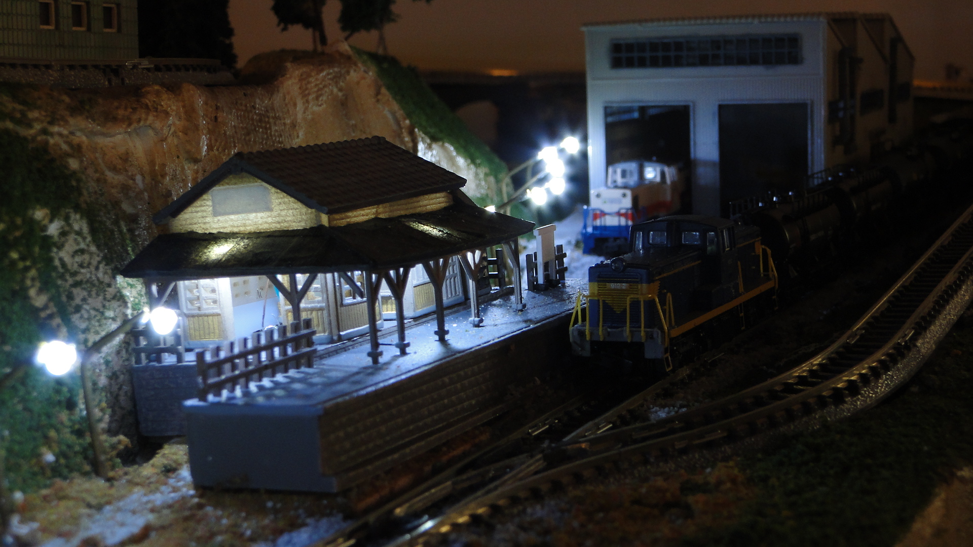
There's a great article on the MAX7219/MAX7221 LED Drivers on arduino.cc that details how to utilise these chips to control a large amount of LEDs (MAX7219/7221 Datasheet.) The layout I've been working on was always going to have a lot of scenery lighting and I'd decided this time to use LEDs over traditional 12v DC Bulbs as they draw less current and can often be a lot brighter. Also, Japan does use a lot more 'white light' when lighting streets and train/traffic signals, so it fits in close enough to the prototype.
LED Drivers are specific intergrated circuits that are designed to control a large amount of LEDs wired up in a matrix. This means that, in the case of the MAX7219/7221, the LEDs will be in rows and columns of 8 for a total of 64 LEDs per chip. The exact wiring dictates that each column contains 8 cathodes and each row 8 anodes. This therefore means that if you apply power to one row, and then ground a column, you will light the associated LED. Of course, this means that if you power two rows and two columns you will in fact have 4 LEDs lit. This is because the matrix is limited in only being able to light specific LEDs on a row-by-row basis.
Fortunately, the Drivers are fast enough to light row after row (selecting the exact LEDs to light by grounding certain columns) making it look like all LEDs are on at the same time. Therefore, you can specify the exact LEDs to light and, in the case of an 8x8 matrix, you can draw pictures, scroll text, etc...
Of course, you are not limited to controlling a matrix. These chips fundamentally just light up 64 LEDs and, for my layout, this should be enough for my scenery requirements. The main issue is actually building a 'distribution point' for getting the 64 pairs of wires out to the LEDs from the chip.
Note: PLEASE make sure you have a 'clean' power supply and it's connected cleanly and solidly. I just spent a day diagnosing why my LEDs stopped working... it was because my 12v power distribution had a dry solder joint... totally frustrating!
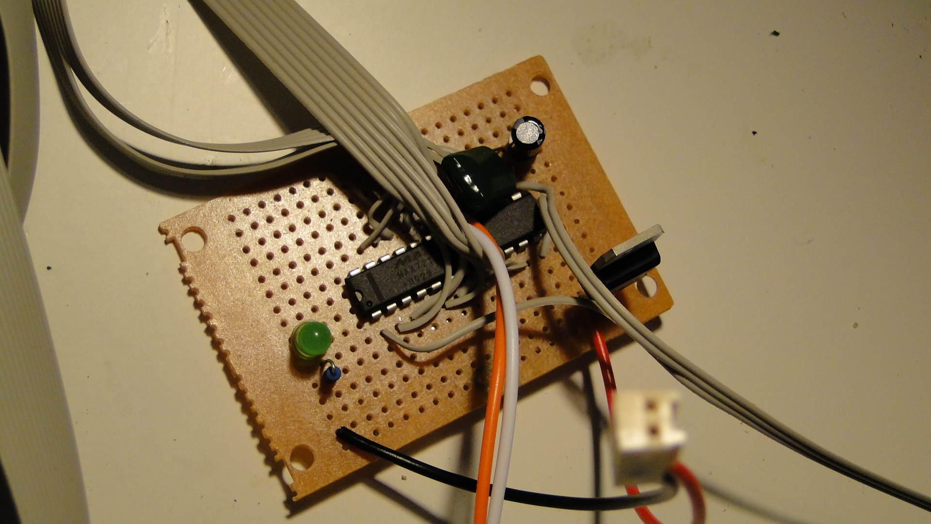
As the chip only has 16 pins (8 rows, 8 columns), one has to split these out into inidividual wires to LEDs.
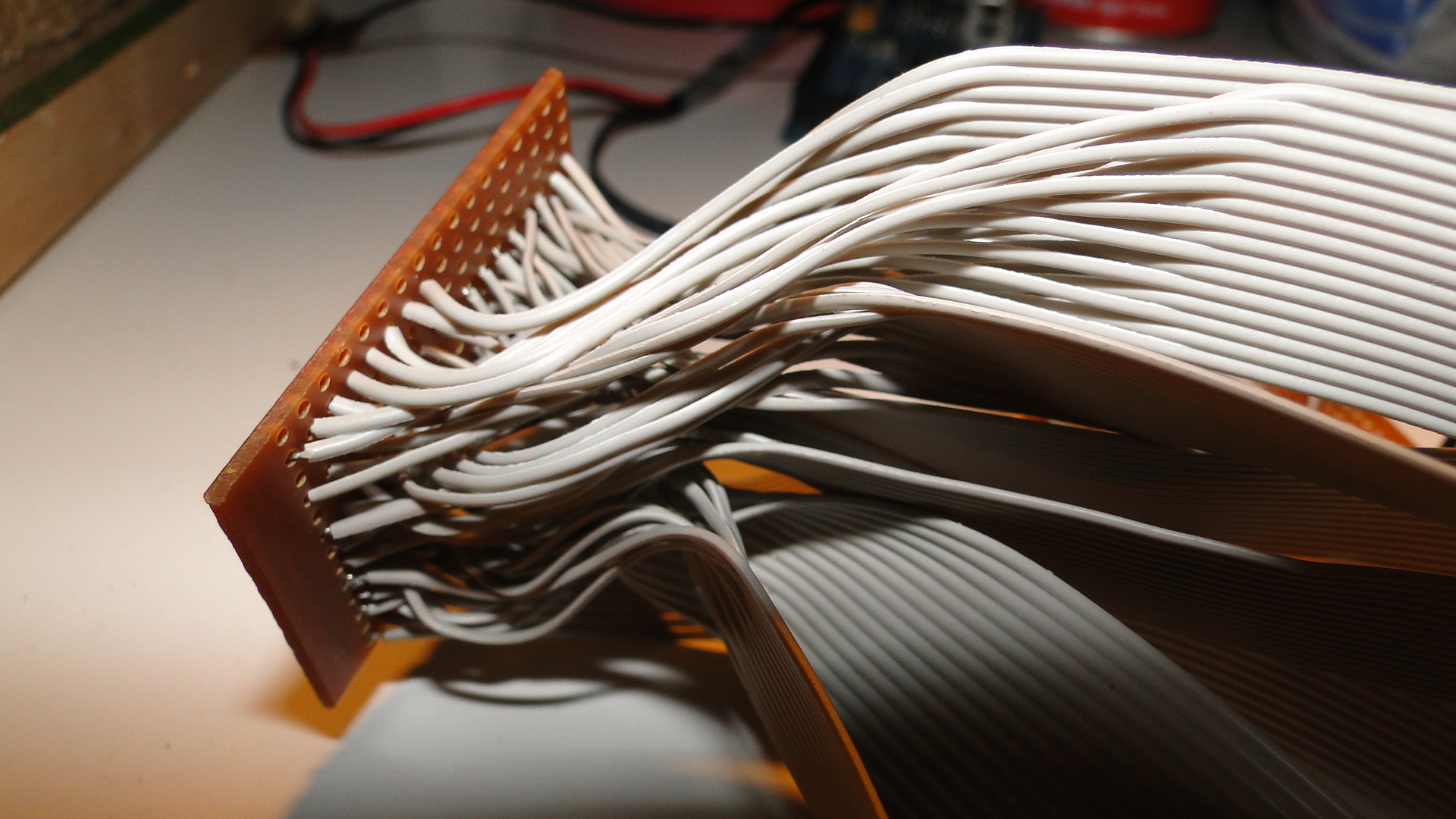
If you happen to have your LEDs in groups/clusters of 8 then you will have a lot less trouble wiring everything up... otherwise you'll need to tediously create a 'distribution board' like I've done here:
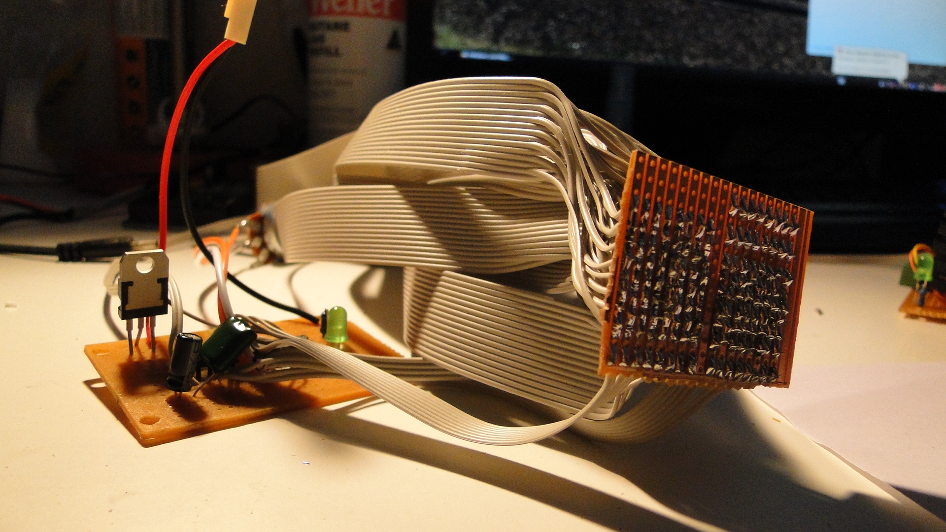
So, once this was together I put some plugs on the end of the ribbon wire and then added header pins to my LED wiring. This then meant I could simply plug the LEDs in as no resistors are required. Trying to work out which way around to put them was quite easy, as they seem to get full voltage if you put them the wrong way! So, be careful, if this happens then quickly reverse the LED.
I then wrote some code to turn my well-lit footpath into a flashing mess...
//pins for the MAX7219
#define CLK_PIN 31
#define LOD_PIN 33
#define DIN_PIN 35

//pins for my L298N throttle
#define THROTTLE_ENABLE 2
#define PWM1_PIN 3
#define PWM2_PIN 4

//library required from:
//http://www.arduino.cc/playground/uploads/Main/LedControl.zip
#include "LedControl.h"

//LED CONTROL... 3 pins and then the number of devices
LedControl lcl=LedControl(DIN_PIN,CLK_PIN,LOD_PIN, 1);

//currently connected lights:
//ROW 0:   NONE.
//ROW 1: Building, Building, Building, Building,
//       Streetlight, Streetlight, Streetlight, Streetlight
//ROW 2-3: NONE.
//ROW 4: Streetlight, Streetlight, Streetlight, Streetlight,
//       Streetlight, Streetlight, Building
//ROW 4-7: NONE.

void setup() {
  //initialise the led driver...
  lcl.shutdown(0, false);   //turn off shutdown..
  lcl.setIntensity(0, 8);   //set the intensity, you can also use the potentiometer.

  //set initial throttle, direction and speed
  pinMode(THROTTLE_ENABLE, OUTPUT);
  digitalWrite(PWM2_PIN, HIGH);
  digitalWrite(PWM1_PIN, LOW);
  analogWrite(THROTTLE_ENABLE, 200);

  //turn on the building lights.
  for (int i = 0; i < 4; i++) lcl.setLed(0,1,i,true);
  lcl.setLed(0,4,6,true);
}

int MS_DELAY = 300; //timing, close enough to train speed.

void loop() {
  //the streetlights are in a bit of a jumbled order:
  //ROW 4: 5,4,3,2,1 and then ROW 1: 4,5,6,7.

  //turn them all on
  for (int x = 5; x >= 0; x--){
    lcl.setLed(0, 4, x, true);
    delay(MS_DELAY);
  }
  for (int x = 4; x < 8; x++){
    lcl.setLed(0, 1, x, true);
    delay(MS_DELAY);
  }

  //now turn them back off
  for (int x = 5; x >= 0; x--){
    lcl.setLed(0,4,x,false);
    delay(MS_DELAY);
  }
  for (int x = 4; x < 8; x++){
    lcl.setLed(0,1,x,false);
    delay(MS_DELAY);
  }
}
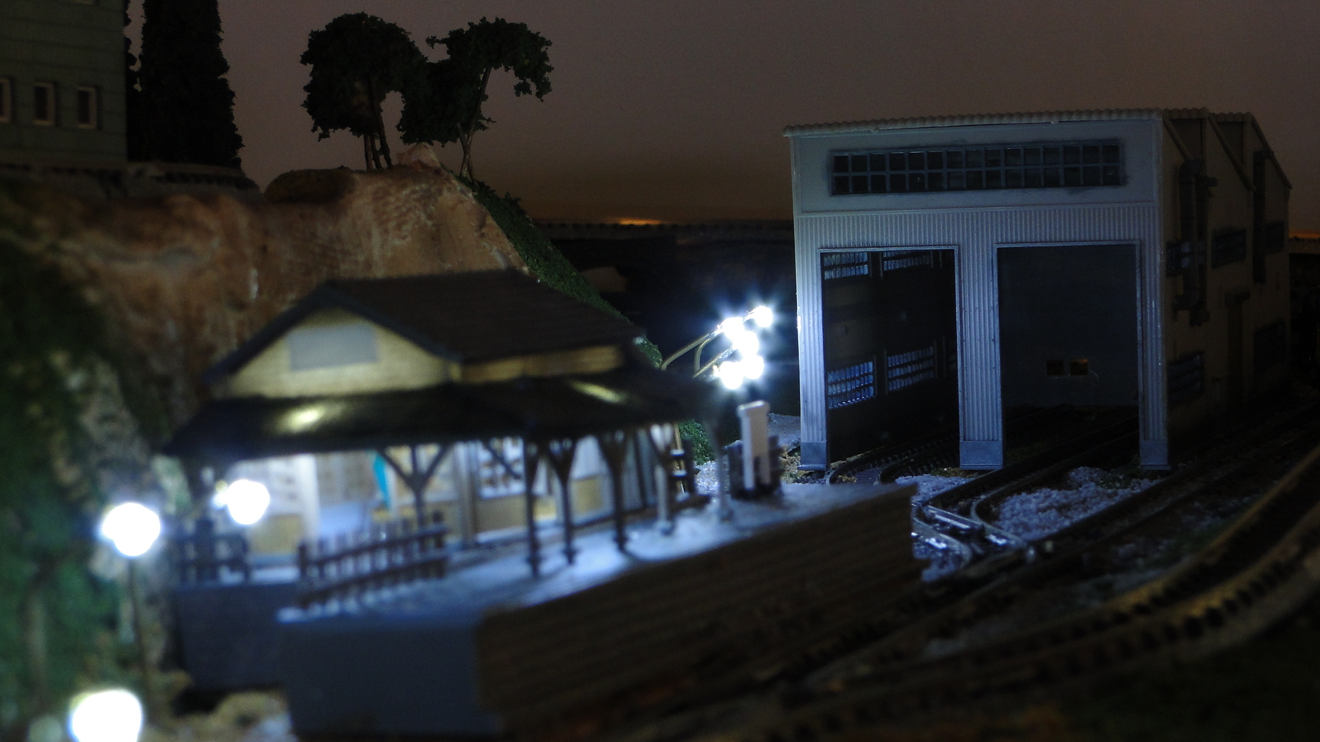
And here was the result, with my homemade street lights:
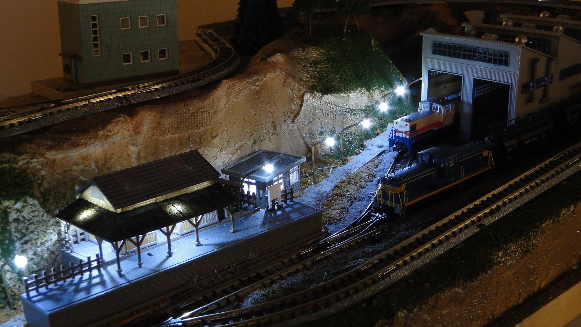
The best thing about these chips is that they can be daisy-chained together to control a total of 512 LEDs off 3 pins. If you think you'll need more than that for your project, then you're crazy... but it can be done. Simply utilise another 3 digital pins of your Arduino to control another 512 LEDs... I shudder to think of something lit that brightly.
Random Photos
Search
Tags
Links - Click for details
- Abandoned Rails (Japan)
- AIRLINE (Shinkansen Photography)
- Akihabara Station
- annexpressのブログ
- Australian Model Railway Magazine
- DCC普及協会ホームページ (Japanese DCC)
- Dead Section (Japanese Track Diagrams)
- Delicious Things (Japanese N Scale DCC)
- Densha Wotorou
- Digital Direct for Windows (DCC Server)
- Don's Dream World – AMAZING N Scale Japanese Layout
- Hatena::Diary
- Japanese N-Scale Modeling Forum
- JR Chiisai
- Kaz-T's blog レインボーライン (Rainbow Line)
- LED Resitance Calculator
- Masioka
- Poppondetta Blog
- RailFan Magazine, Japan
- Railmind
- Railway Travelers' Room
- Serenity Valley
- Shashinka Ichiban
- Shuzuku
- Sumida Crossing
- The next station is…
- Tomix N Gauge Track and Japanese N Gauge Trains
- TT Forums (Transport Tycoon Deluxe)
- 名鉄尾西線の貨物列車 (Nagoya: Meitetsu Freight)
- 日本型Nゲージ DCC改造例のご紹介 (Okiraku DCC)
- 泰 茅 轍 道 (Taichi Railway)
- 箱庭登山鉄道製作記 (Hakone-Tozan Layout Blog)
Archive
- July 2026
- May 2026
- April 2026
- March 2026
- February 2026
- January 2026
- November 2025
- October 2025
- September 2025
- August 2025
- July 2025
- June 2025
- February 2025
- January 2025
- November 2024
- September 2024
- August 2024
- July 2024
- June 2024
- May 2024
- April 2024
- March 2024
- February 2024
- December 2023
- October 2023
- September 2023
- August 2023
- July 2023
- June 2023
- May 2023
- April 2023
- March 2023
- December 2022
- November 2022
- October 2022
- April 2022
- March 2022
- February 2022
- January 2022
- December 2021
- November 2021
- September 2021
- August 2021
- July 2021
- May 2021
- March 2021
- February 2021
- January 2021
- October 2020
- September 2020
- August 2020
- July 2020
- June 2020
- May 2020
- April 2020
- March 2020
- January 2020
- December 2019
- November 2019
- October 2019
- September 2019
- August 2019
- July 2019
- June 2019
- April 2019
- March 2019
- February 2019
- January 2019
- December 2018
- November 2018
- October 2018
- September 2018
- August 2018
- July 2018
- June 2018
- May 2018
- April 2018
- March 2018
- January 2018
- December 2017
- November 2017
- October 2017
- September 2017
- August 2017
- July 2017
- June 2017
- May 2017
- March 2017
- February 2017
- January 2017
- December 2016
- November 2016
- October 2016
- September 2016
- August 2016
- July 2016
- June 2016
- May 2016
- February 2016
- November 2015
- October 2015
- September 2015
- August 2015
- July 2015
- June 2015
- May 2015
- April 2015
- March 2015
- February 2015
- January 2015
- December 2014
- November 2014
- August 2014
- July 2014
- May 2014
- April 2014
- March 2014
- December 2013
- November 2013
- October 2013
- June 2013
- August 2012
- April 2012
- March 2012
- February 2012
- November 2011
- October 2011
- September 2011
- July 2011
- June 2011
- May 2011
- April 2011
- March 2011
- February 2011
- January 2011
- December 2010
- November 2010
- October 2010
- September 2010
- August 2010
- June 2010
- May 2010
- April 2010
- March 2010
- February 2010
- January 2010
- December 2009
- November 2009
- October 2009
- August 2009
- January 2009
- December 2008
- November 2008
- October 2008
- September 2008
- July 2008
March 22nd, 2010 - 03:16
This is an interesting chip you’ve found! I’ll have to get some and play around. The TLC5941/TLC59401/TLC5940 that I’ve been playing with sink 16 channels directly. Matrix-multiplexing requires and additional current-sourcing shift-register for each TLC594*.
If it makes you feel better, I’m now at a loss to guess what new and interesting use you’ll be putting your Arduino to next.
March 22nd, 2010 - 13:12
Don,
Those chips are much nicer if you want better control over the LEDs. PWM dimming would be a neat feature indeed. The chip here only sets one standard intensity and it’s really expected to only control 64 of the same type of LEDs (i.e. for signs/displays.)
Fortunately I’m not that much of a perfectionist, so… as long as the LEDs come on, I’m happy :)
Meanwhile, the next project is a while off as I’m still fighting with IR Detection. I can’t get consistent results and so have forked out for the Sharp units, but am attempting another method as well.
March 24th, 2010 - 11:45
I was thinking about your problems the other day, and while thumbing through one of Forrest Mims’s excellent handbooks, wondered if you might could do something with Hall-effect sensors? You could set up an array—maybe just two—along side each track in the barn. I don’t know how sensitive they would be to the locos’ motors though.
March 24th, 2010 - 15:25
I was more thinking these:
http://toysdownunder.com/arduino/sensors/infrared-emmitter-detector.html
As pairs on either side of the rails… they’re transparent and would be a nice addition to the shed once painted… I’d then just sum up their resistance… or something to that effect… or I could use a 4051 multiplexer to read their analog voltages…
But we’ll see how the Sharp units go first.