


 Melbourne BG SCS Train Timetable


InfraRed + Arduino revisited
Ok, after failing (more-or-less miserably) with the previous attempt at IR distance detection, I went out and purchased 4 of the Sharp GP2D12 from an eBay Store and put them to work. Finally I had a detection system working, but before this I had also attempted another method using larger IR emitter/detectors that I'd bought from Dip Micro.
Attempt 1: QRD1114, and other smaller IR detectors
See the previous blog post here
Attempt 2: IR Emitter/Detector pairing
Since my previous attempt had failed, I'd decided that if the smaller emitters could not produce enough light to avoid sunlight/roomlight interference, then boosting both the emitter and detector should help. I'd accidently purchased a collection of 10x emitter/collector pairs of IR diodes and so I put these to work in the typical setup and tested them out. These were both 3mm in diameter and, depending on the resistors used, could emit a lot more light (tested via my digital camera.)
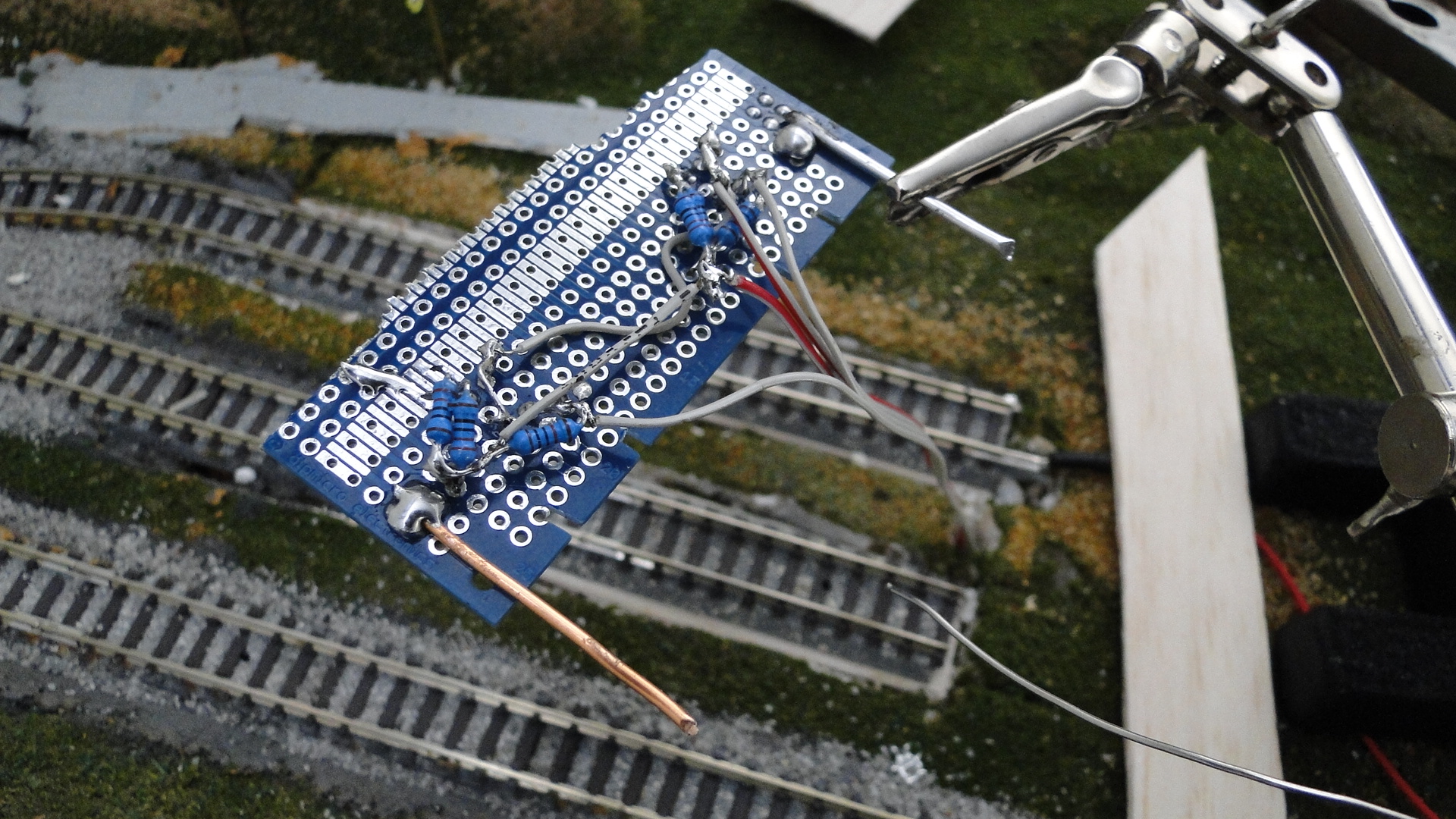
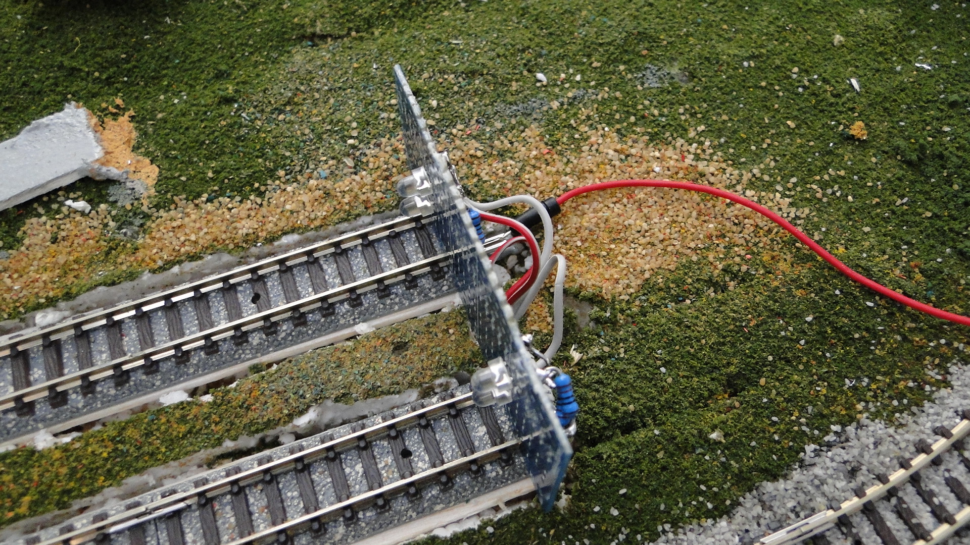
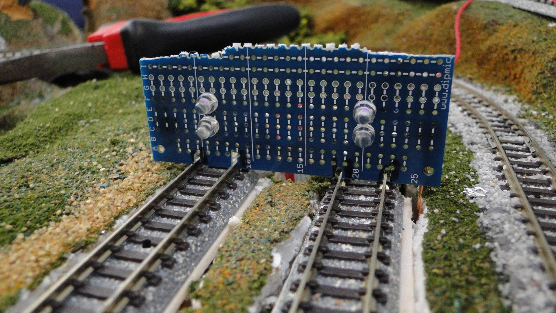
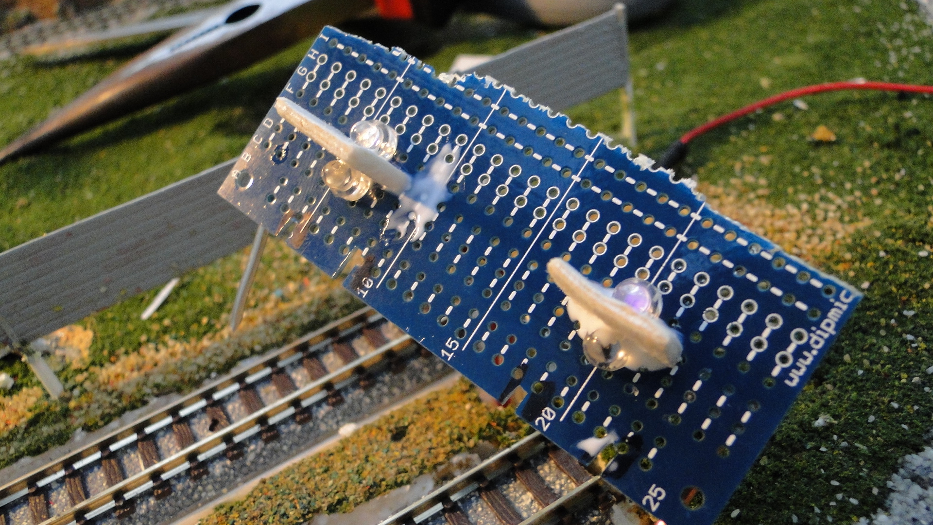
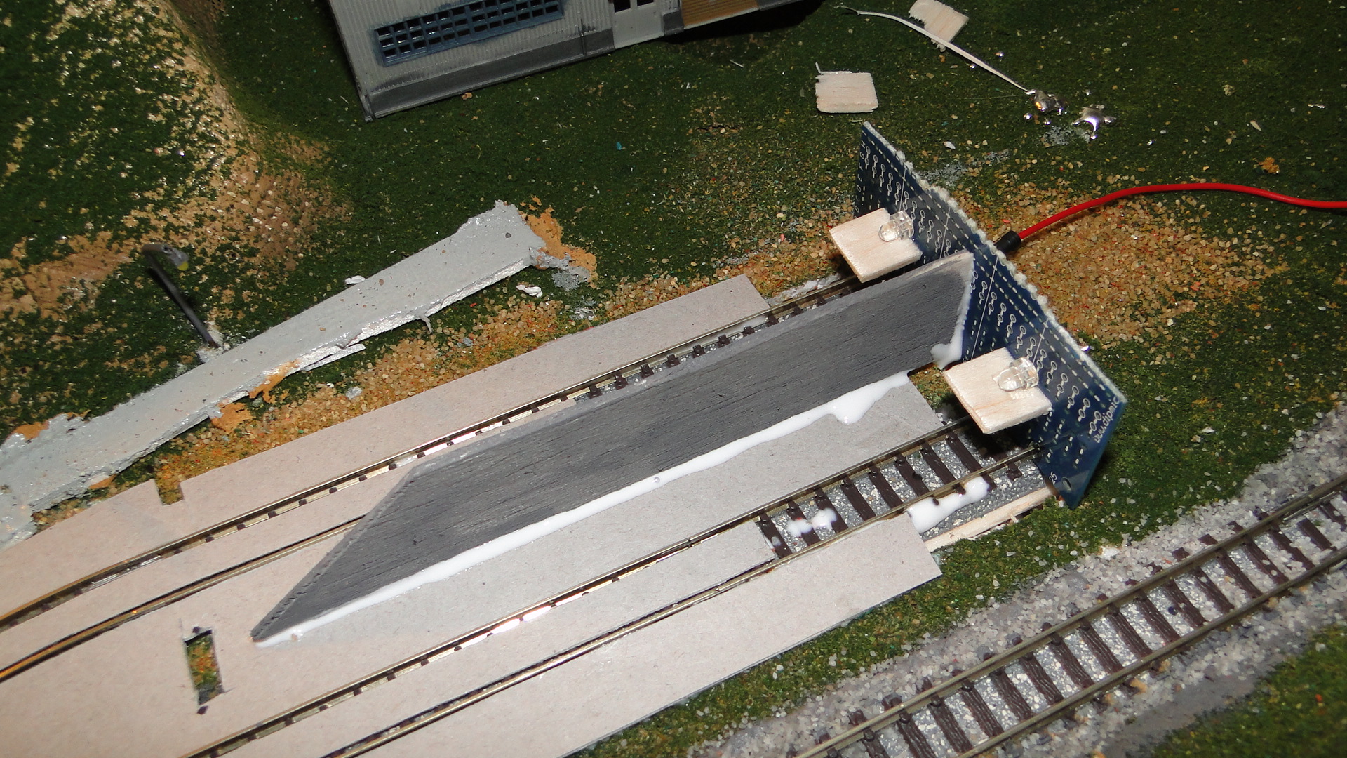
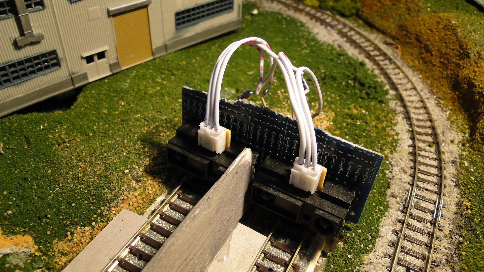
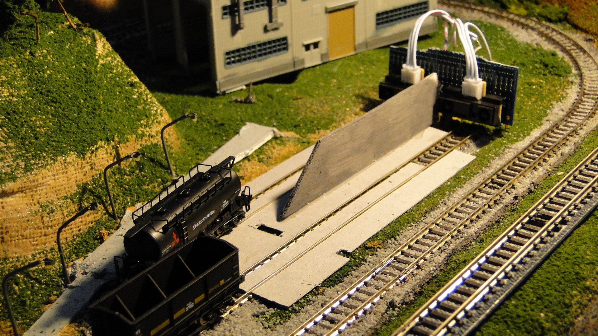
The setup was the same as per usual... mounted horizontally at the end of the tracks to ensure that the light would reflect (as much as possible) off the approaching train.
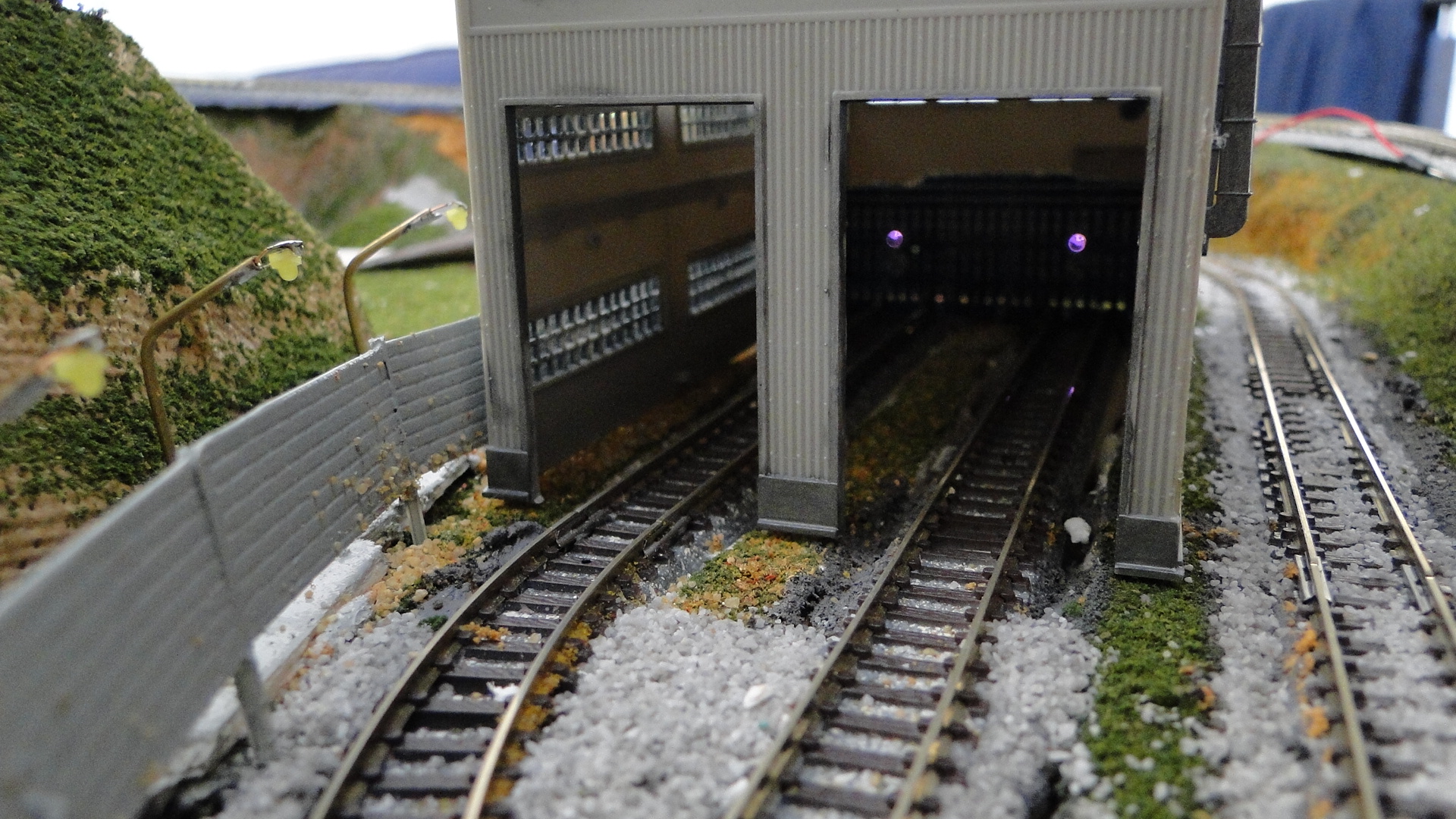
Working with IR at night-time has it's benefits. Your room is usually lit under artificial light and so the amount of IR in the 'air' is low. I therefore had some pretty good results with this setup, but of course, come daylight, everything went out the window (or in the window, as the case may be.) Since this detector was to be in the back of an engine shed, I'd thought that I could block out the windows and make a little dark room, but my detectors were still too unreliable.
This experiment was, in the end, functional, but not to the degree that I'd wanted and so I therefore opted for the off-the-shelf Sharp detector.
Note: The goal here was to use the pair at the end of the track to sense distance. It now seems that the best method will be to detect 'occupation' and I will again test this method with a series of emitter/detector pairs along the track to sense when a train is approaching.
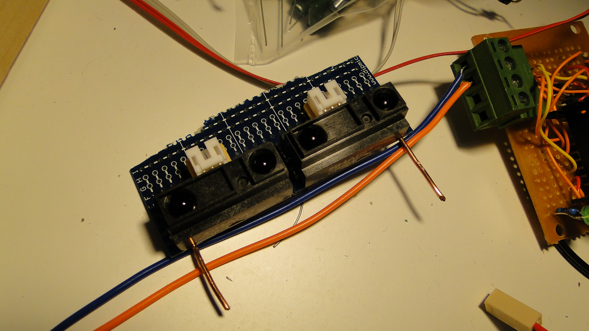
Attempt 3: Sharp GP2D12
After being concerned about sizing and the minimum distance that these detectors would work from, I decided I'd just bite the bullet and try them out.
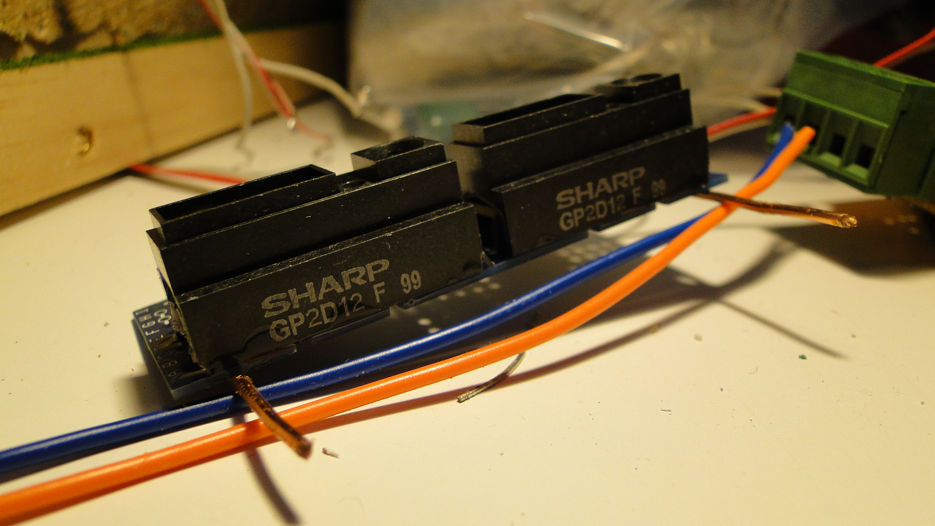
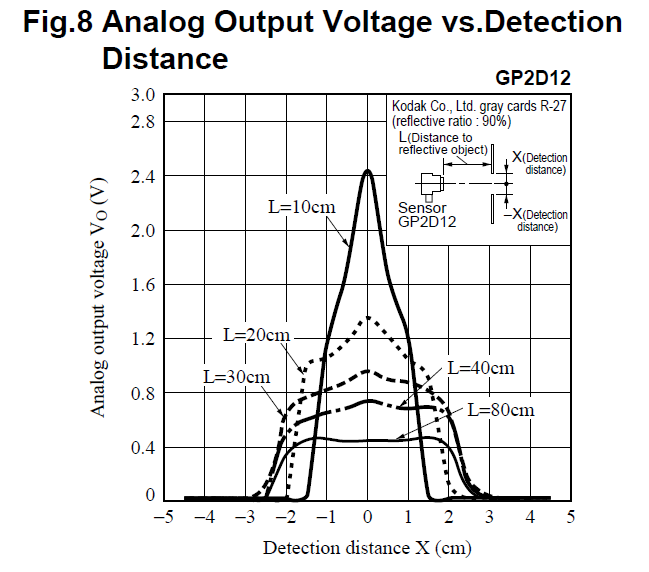
I ended up purchasing 4 quite cheaply on eBay and they arrived from the UK in a short amount of time. I then realised that the versions I'd bought were optimised for detection between 10cm and 70cm. This really sucks, as I'd want the range to be much closer to the detector, as 10cm is a long way for a no-detection zone. I then looked at the graphs showing the voltage compared to distance:
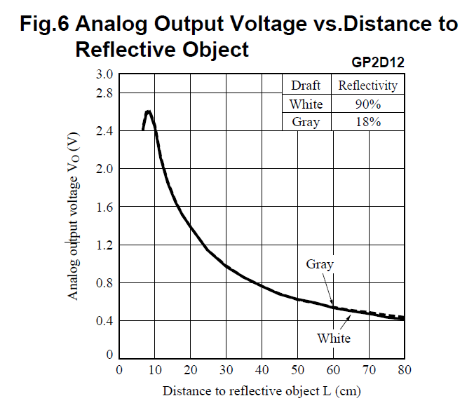
It turns out that this datasheet shows you the comparison of the various detectors that Sharp makes. There seems to be one detector better suited for my project, but.. as they say... hindsight is a bitch. Even worse is that Toys Downunder currently has them in stock!
Although the 'optimum' detecting distance for unit is around 10cm, the detector still gives valid voltage results right down to around 3cm. The only issue here is that the voltage difference is not always increasing! I therefore have to take the value and use it in different scenarios (i.e. when cruising, braking, stopped, etc...)
The setup was the same as usual:
So, to deal with this, I needed to work on the voltage change... in steps of around 0.25v. If you happen to implement this yourself, you'll notice straight away that the voltage returned by this unit is not constant when the vehicle is stopped or approaching... it's perpetually flitting around +-0.5v and this can be a real nightmare. Due to this I only choose to detect larger changes which means only reading the sensor if it is +-25 of the current read value.
The basic idea is to determine the deceleration of the vehicle dependent on it's distance from the wall. The final testing code is listed next. Note that this also contains my multiplexer, thottle and also an off-the-shelf LCD for which you can find tutorials here.
#define MIN_SPEED 50
#define CRAWL_SPEED 85
#define MAX_SPEED 125

#include <LiquidCrystal.h>
LiquidCrystal lcd(30, 31, 40, 41, 42, 43);

#define STROBE_PIN 50
#define INHIBIT_PIN 51

#define BIT1_PIN 21
#define BIT2_PIN 23
#define BIT3_PIN 25
#define BIT4_PIN 27

#define DIRECTION1_PIN 52
#define DIRECTION2_PIN 53

void initMultiplexer() {
  //set the output mode.
  pinMode(INHIBIT_PIN,OUTPUT);
  pinMode(STROBE_PIN,OUTPUT);
  pinMode(BIT1_PIN,OUTPUT);
  pinMode(BIT2_PIN,OUTPUT);
  pinMode(BIT3_PIN,OUTPUT);
  pinMode(BIT4_PIN,OUTPUT);
  pinMode(DIRECTION1_PIN,OUTPUT);
  pinMode(DIRECTION2_PIN,OUTPUT);
  //initial state
  digitalWrite(INHIBIT_PIN, HIGH); //high = off.
  digitalWrite(STROBE_PIN, LOW); //toggle low -> high -> low to set output.
  digitalWrite(BIT1_PIN, LOW);
  digitalWrite(BIT2_PIN, LOW);
  digitalWrite(BIT3_PIN, LOW);
  digitalWrite(BIT4_PIN, LOW);
}

void change(int out) {
  //work out bits
  Serial.print((out >> 3) & 0x01);
  if ((out >> 3) & 0x01) digitalWrite(BIT4_PIN, HIGH);
  else digitalWrite(BIT4_PIN, LOW);
  if ((out >> 2) & 0x01) digitalWrite(BIT3_PIN, HIGH);
  else digitalWrite(BIT3_PIN, LOW);
  Serial.print((out >> 2) & 0x01);
  if ((out >> 1) & 0x01) digitalWrite(BIT2_PIN, HIGH);
  else digitalWrite(BIT2_PIN, LOW);
  Serial.print((out >> 1) & 0x01);
  if ((out) & 0x01) digitalWrite(BIT1_PIN, HIGH);
  else digitalWrite(BIT1_PIN, LOW);
  Serial.println((out >> 0) & 0x01);
  //toggle strobe
  digitalWrite(STROBE_PIN, HIGH);
  delay(50);
  digitalWrite(STROBE_PIN, LOW);
}

void setup() {
  initMultiplexer();
  Serial.begin(9600);
  lcd.begin(16, 2);
}

void updateSensorValue(int& tgt, int latest)
{
   int threshold = 25;
   if ((latest < (tgt - threshold)) || (latest > (tgt + threshold))) tgt = latest;
}

void pulseMultiplexer() {
  //toggle inhibit to low to actually output power
  digitalWrite(INHIBIT_PIN,LOW);
  delay(125); //25ms is long enough.
  digitalWrite(INHIBIT_PIN,HIGH);
  delay(1500); //now delay before going to next point.
}

int thresholds[4] = {9999,0,9999,0};

int t = millis();
int oldT = millis(), dirT = oldT;
int a1;
int a2;
int spd = 0;
int dir = 0;

int train_status = 0;
int sensor = 0;
int point = 0;

void loop() {
  t = millis();

  if ((t - oldT) > 50) {
    updateSensorValue(a1, analogRead(0));
    updateSensorValue(a2, analogRead(1));

    sensor = a1;
    if (point == 1) sensor = a2;

    switch(train_status) {
      case 0: //accelerating
        if (spd < MIN_SPEED) spd = MIN_SPEED;
        spd += 2;
        if (spd > MAX_SPEED) {
          train_status = 1;
          spd = MAX_SPEED;
        }
        break;
      case 1: //travelling
        break;
      case 2: //braking
        spd -= 10;
        if (spd < CRAWL_SPEED) spd = CRAWL_SPEED;
        break;
      case 3: //paused
        spd = 0;
        break;
    }

    if (dir == 1) {
      if ((t - dirT > 1250) && (train_status == 0 || train_status == 1)) {
        train_status = 2;
        dirT = t;
      }
      else if ((t - dirT > 2000) && train_status == 2 && spd == CRAWL_SPEED) {
        train_status = 3;
        dirT = t;
      }
      else if ((t - dirT > 500) && train_status == 3)
      {
        train_status = 0;
        dir = !dir;
        dirT = t;
        //switch point
        change(3);
        if (point == 0) {
          digitalWrite(DIRECTION1_PIN, HIGH);
          digitalWrite(DIRECTION2_PIN, LOW);
          Serial.println(0);
        } else if (point == 1) {
          digitalWrite(DIRECTION1_PIN, LOW);
          digitalWrite(DIRECTION2_PIN, HIGH);
          Serial.println(1);
        }
        pulseMultiplexer();
        point = !point;
      }
    }
    else if (dir == 0)
    {
      //we should be checking which point we're about to hit first?
      /*if (a1 > 400 && dir == 0) {
        spd = 0;
        dir = !dir;
        train_status = 0;
      } else if (a1 > 300 && dir == 0) spd = 70;
      else if (a1 > 200 && dir == 0) spd = 90;
      else if (a1 > 150 && dir == 0) spd = 110;
      else spd = 125;*/
      if (train_status != 3) {
        if (sensor > 400) {
          train_status = 3;
          dirT = t;
        } else if (sensor > 300) {
          train_status = 2;
        }
      } else if (t - dirT > 500 && train_status == 3) {
        train_status = 0;
        dir = !dir;
        dirT = t;
      }
    }

    lcd.clear();
    lcd.setCursor(0, 0);
    lcd.print("");
    lcd.setCursor(0, 0);
    lcd.print(a1);
    lcd.setCursor(0, 1);
    lcd.print("");
    lcd.setCursor(0, 1);
    lcd.print(a2);

    lcd.setCursor(5, 0);
    lcd.print(thresholds[0]);
    lcd.setCursor(7, 0);
    lcd.print(thresholds[1]);

    lcd.setCursor(5, 1);
    lcd.print(thresholds[2]);
    lcd.setCursor(7, 1);
    lcd.print(thresholds[3]);

    lcd.setCursor(11, 0);
    lcd.print(spd);
    lcd.setCursor(11, 1);
    lcd.print(dir);
    lcd.setCursor(15, 1);
    lcd.print(train_status);

    oldT = t;
  }

  if (a1 < thresholds[0]) thresholds[0] = a1;
  if (a1 > thresholds[1]) thresholds[1] = a1;
  if (a2 < thresholds[2]) thresholds[2] = a2;
  if (a2 > thresholds[3]) thresholds[3] = a2;

  if (dir == 0) {
    digitalWrite(3, HIGH);
    digitalWrite(4, LOW);
  } else {
    digitalWrite(4, HIGH);
    digitalWrite(3, LOW);
  }

  analogWrite(2, spd);
}
From the above, we get the following action... note that the whole process here is automated (throttle, detection, point switching):
Conclusion
This sensor worked much better than the previous attempts... but it's still not the best. I think I might now just grab one of the GP2D120s (as it would simply be plug-and-play) and see what happens. Also lighting plays an affect here too, it might just be easier in the end to have a strip of LDRs to work out where the train is... but everything has it's good and bad side!
The other option will be to have a spaced strip of detectors down one side of the track and emitters on the other. This will be like your tandy/radio-shack store that beep-beeps when you trip the beam... we'll see how well it works.
Controlling lots of LEDs with your Arduino
There's a great article on the MAX7219/MAX7221 LED Drivers on arduino.cc that details how to utilise these chips to control a large amount of LEDs (MAX7219/7221 Datasheet.) The layout I've been working on was always going to have a lot of scenery lighting and I'd decided this time to use LEDs over traditional 12v DC Bulbs as they draw less current and can often be a lot brighter. Also, Japan does use a lot more 'white light' when lighting streets and train/traffic signals, so it fits in close enough to the prototype.
LED Drivers are specific intergrated circuits that are designed to control a large amount of LEDs wired up in a matrix. This means that, in the case of the MAX7219/7221, the LEDs will be in rows and columns of 8 for a total of 64 LEDs per chip. The exact wiring dictates that each column contains 8 cathodes and each row 8 anodes. This therefore means that if you apply power to one row, and then ground a column, you will light the associated LED. Of course, this means that if you power two rows and two columns you will in fact have 4 LEDs lit. This is because the matrix is limited in only being able to light specific LEDs on a row-by-row basis.
Fortunately, the Drivers are fast enough to light row after row (selecting the exact LEDs to light by grounding certain columns) making it look like all LEDs are on at the same time. Therefore, you can specify the exact LEDs to light and, in the case of an 8x8 matrix, you can draw pictures, scroll text, etc...
Of course, you are not limited to controlling a matrix. These chips fundamentally just light up 64 LEDs and, for my layout, this should be enough for my scenery requirements. The main issue is actually building a 'distribution point' for getting the 64 pairs of wires out to the LEDs from the chip.
Note: PLEASE make sure you have a 'clean' power supply and it's connected cleanly and solidly. I just spent a day diagnosing why my LEDs stopped working... it was because my 12v power distribution had a dry solder joint... totally frustrating!
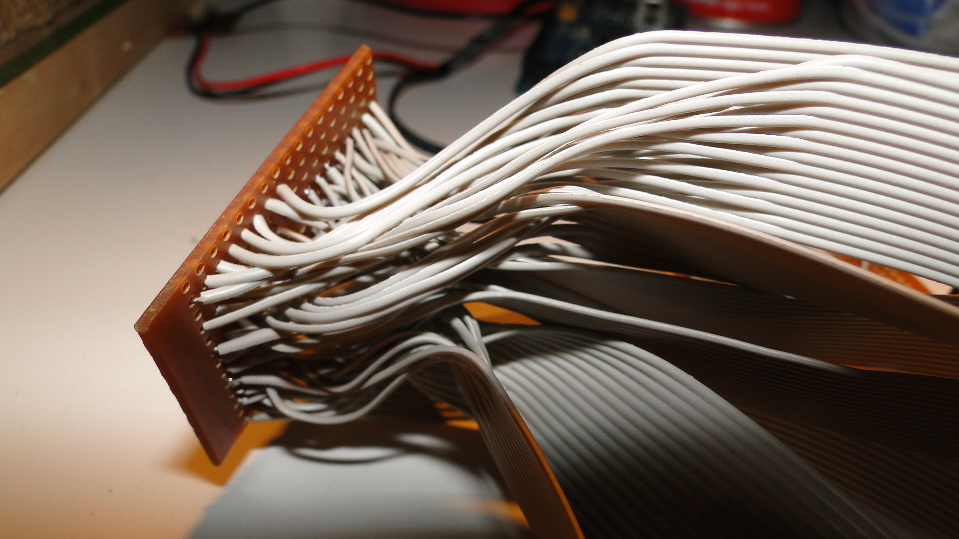
As the chip only has 16 pins (8 rows, 8 columns), one has to split these out into inidividual wires to LEDs.
If you happen to have your LEDs in groups/clusters of 8 then you will have a lot less trouble wiring everything up... otherwise you'll need to tediously create a 'distribution board' like I've done here:
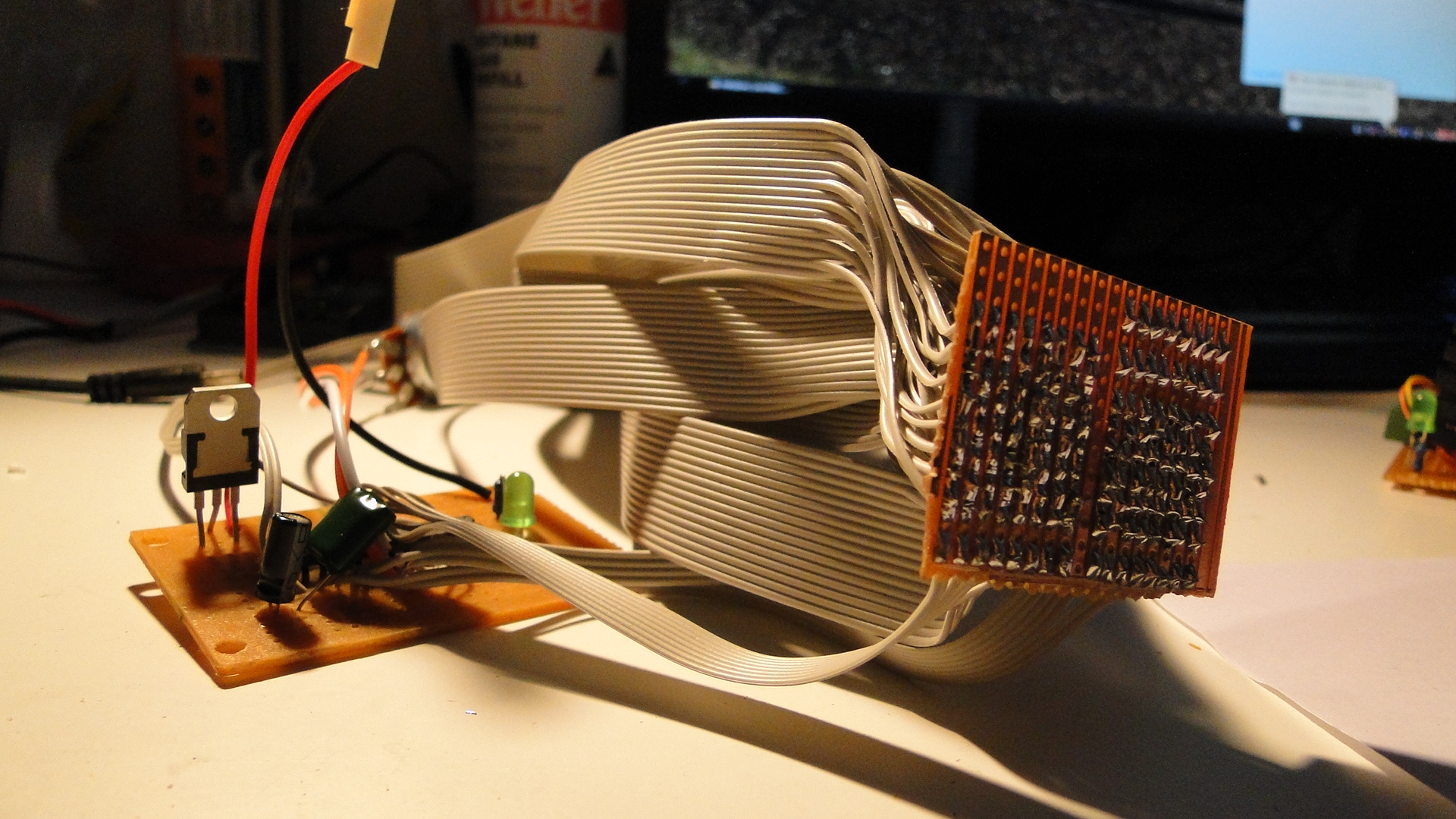
So, once this was together I put some plugs on the end of the ribbon wire and then added header pins to my LED wiring. This then meant I could simply plug the LEDs in as no resistors are required. Trying to work out which way around to put them was quite easy, as they seem to get full voltage if you put them the wrong way! So, be careful, if this happens then quickly reverse the LED.
I then wrote some code to turn my well-lit footpath into a flashing mess...
//pins for the MAX7219
#define CLK_PIN 31
#define LOD_PIN 33
#define DIN_PIN 35

//pins for my L298N throttle
#define THROTTLE_ENABLE 2
#define PWM1_PIN 3
#define PWM2_PIN 4

//library required from:
//http://www.arduino.cc/playground/uploads/Main/LedControl.zip
#include "LedControl.h"

//LED CONTROL... 3 pins and then the number of devices
LedControl lcl=LedControl(DIN_PIN,CLK_PIN,LOD_PIN, 1);

//currently connected lights:
//ROW 0:   NONE.
//ROW 1: Building, Building, Building, Building,
//       Streetlight, Streetlight, Streetlight, Streetlight
//ROW 2-3: NONE.
//ROW 4: Streetlight, Streetlight, Streetlight, Streetlight,
//       Streetlight, Streetlight, Building
//ROW 4-7: NONE.

void setup() {
  //initialise the led driver...
  lcl.shutdown(0, false);   //turn off shutdown..
  lcl.setIntensity(0, 8);   //set the intensity, you can also use the potentiometer.

  //set initial throttle, direction and speed
  pinMode(THROTTLE_ENABLE, OUTPUT);
  digitalWrite(PWM2_PIN, HIGH);
  digitalWrite(PWM1_PIN, LOW);
  analogWrite(THROTTLE_ENABLE, 200);

  //turn on the building lights.
  for (int i = 0; i < 4; i++) lcl.setLed(0,1,i,true);
  lcl.setLed(0,4,6,true);
}

int MS_DELAY = 300; //timing, close enough to train speed.

void loop() {
  //the streetlights are in a bit of a jumbled order:
  //ROW 4: 5,4,3,2,1 and then ROW 1: 4,5,6,7.

  //turn them all on
  for (int x = 5; x >= 0; x--){
    lcl.setLed(0, 4, x, true);
    delay(MS_DELAY);
  }
  for (int x = 4; x < 8; x++){
    lcl.setLed(0, 1, x, true);
    delay(MS_DELAY);
  }

  //now turn them back off
  for (int x = 5; x >= 0; x--){
    lcl.setLed(0,4,x,false);
    delay(MS_DELAY);
  }
  for (int x = 4; x < 8; x++){
    lcl.setLed(0,1,x,false);
    delay(MS_DELAY);
  }
}
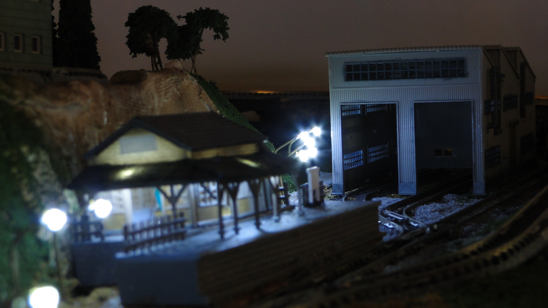
And here was the result, with my homemade street lights:
The best thing about these chips is that they can be daisy-chained together to control a total of 512 LEDs off 3 pins. If you think you'll need more than that for your project, then you're crazy... but it can be done. Simply utilise another 3 digital pins of your Arduino to control another 512 LEDs... I shudder to think of something lit that brightly.
Multiplexing + Controlling points (or other high-current devices) with an Arduino
OK, the Arduino only has a limited number of pins at your disposal (more depending on what model you are in possession of) but, don't fret, there is a way of extending the amount of inputs _and_ outputs.
Multiplexing, as defined by Wikipedia is:
In telecommunications and computer networks, multiplexing (also known as muxing) is a process where multiple analog message signals or digital data streams are combined into one signal over a shared medium. The aim is to share an expensive resource. For example, in telecommunications, several phone calls may be transferred using one wire. It originated in telegraphy, and is now widely applied in communications.
In our situation, we're using digital data and our shared medium will be a smaller group of pins than the amount required if we were to hook up the sum total of devices able to be connected. So, in our case we will use the CD4514BC "4-Bit Latched/4-to-16 Line Decoder" to control/read 16 digital lines from only 6 digital pins.
Quick note:
If you don't mind that the chip is always outputting then just ground the Inhibit pin. It'll save you a pin on your Arduino!
First, a short stint of binary logic. Our numbering scheme will start from 0 and end at 15, giving us 16 possible values. This can be written in binary using 4 digits.
| Bit 4 | Bit 3 | Bit 2 | Bit 1 | Value | Bit 4 | Bit 3 | Bit 2 | Bit 1 | Value | |
|---|---|---|---|---|---|---|---|---|---|---|
| 0 | 0 | 0 | 0 | 0 | 1 | 0 | 0 | 0 | 8 | |
| 0 | 0 | 0 | 1 | 1 | 1 | 0 | 0 | 1 | 9 | |
| 0 | 0 | 1 | 0 | 2 | 1 | 0 | 1 | 0 | 10 | |
| 0 | 0 | 1 | 1 | 3 | 1 | 0 | 1 | 1 | 11 | |
| 0 | 1 | 0 | 0 | 4 | 1 | 1 | 0 | 0 | 12 | |
| 0 | 1 | 0 | 1 | 5 | 1 | 1 | 0 | 1 | 13 | |
| 0 | 1 | 1 | 0 | 6 | 1 | 1 | 1 | 0 | 14 | |
| 0 | 1 | 1 | 1 | 7 | 1 | 1 | 1 | 1 | 15 |
Right, from this table you can see that by setting the Bits to either '1' or '0' we can, with 4 bits, create the numbers from 0 to 15. Now, this is how the input of the CD4514BC Line Decoder works; it accepts digital input on 4 pins, and dependent on whether they are high or low, will output a +5v on the decoded output pin. The chip has, of course, 16 output pins.
The only catch to using this chip is that it also requires 'Strobe' and 'Inhibit' digital inputs. It is called a 'Latched' Line Decoder since it actually holds the output that you have selected. So, the basic idea when controlling it is to:
- 1 - Set the 4 bits to the desired output
- 2 - 'Toggle' the 'Strobe' pin. This means setting it to 'HIGH' and then 'LOW' again (this then 'latches' the next pin to output on)
- 3 - Set the 'Inhibit' pin 'LOW' to output on this pin. When this is 'HIGH', there will never be any output.
Here is the wiring I have used for the CD4514BC:
Dragging the 'Inhibit' HIGH should prevent the points from erratic data on the pins when there is no proper input signal.
From this we can see that we can control 16 devices. The only note is that the multiplexer can only ever output on one pin at a time.
Controlling this chip is quite simple. The steps, as outlined above, are documented in the following code:
#define STROBE_PIN 51
#define INHIBIT_PIN 53
#define BIT1_PIN 31
#define BIT2_PIN 33
#define BIT3_PIN 35
#define BIT4_PIN 37
#define DIRECTION1_PIN 22
#define DIRECTION2_PIN 24
#define TOTAL_OUTPUTS 5 //should 16, but we're only controlling 5 pins for now.

void setup() {
  Serial.begin(9600);
  //set the output mode.
  pinMode(INHIBIT_PIN,OUTPUT);
  pinMode(STROBE_PIN,OUTPUT);
  pinMode(BIT1_PIN,OUTPUT);
  pinMode(BIT2_PIN,OUTPUT);
  pinMode(BIT3_PIN,OUTPUT);
  pinMode(BIT4_PIN,OUTPUT);
  //initial state
  digitalWrite(INHIBIT_PIN, HIGH); //high = off.
  digitalWrite(STROBE_PIN, LOW); //toggle low -> high -> low to set output.
  digitalWrite(BIT1_PIN, LOW);
  digitalWrite(BIT2_PIN, LOW);
  digitalWrite(BIT3_PIN, LOW);
  digitalWrite(BIT4_PIN, LOW);
}

void changeOutputPin(int out) {
  //work out bits
  if (out >> 3 & 0x01) digitalWrite(BIT4_PIN, HIGH);
  else digitalWrite(BIT4_PIN, LOW);
  if ((out >> 2) & 0x01) digitalWrite(BIT3_PIN, HIGH);
  else digitalWrite(BIT3_PIN, LOW);
  if ((out >> 1) & 0x01) digitalWrite(BIT2_PIN, HIGH);
  else digitalWrite(BIT2_PIN, LOW);
  if ((out) & 0x01) digitalWrite(BIT1_PIN, HIGH);
  else digitalWrite(BIT1_PIN, LOW);

  //toggle strobe
  digitalWrite(STROBE_PIN, HIGH);
  digitalWrite(STROBE_PIN, LOW);
}

int currentOutput = 0;
int switchDir = 0;
void loop() {
  changeOutputPin(currentOutput);
  currentOutput++;
  if (currentOutput > TOTAL_OUTPUTS) {
    //only control 8 outputs... change the dir once looped.
    currentOutput = 0;
    switchDir = !switchDir;
    if (switchDir == 1) {
      digitalWrite(DIRECTION1_PIN, HIGH);
      digitalWrite(DIRECTION2_PIN, LOW);
    } else {
      digitalWrite(DIRECTION1_PIN, LOW);
      digitalWrite(DIRECTION2_PIN, HIGH);
    }
  }
  //toggle inhibit to low to actually output power
  digitalWrite(INHIBIT_PIN,LOW);
  delay(25); //25ms is long enough.
  digitalWrite(INHIBIT_PIN,HIGH);
  delay(1500); //now delay before going to next point.
}.
Controlling Point Motors
The Tomix Finetrack points I use on my layout have in-built electromagnets to change their direction. Electromagnets are known to suck a large amount of current in a short burst as they receive power and begin to 'throw'. Due to this, powering one directly off one of the Arduino's output pins is not recommended. Another issue is that the electromagnets will heat up if they are constantly powered. Due to this, they require an external power source controlled in short bursts.
A H-Bridge is used when controlling the actual model locomotives and here one will also be used to control the point magnets. H-Bridges are a great solution to the above issue as they utilise an isolated power supply and can output a reversed polarity. The point magnets from Tomix are only 2-wire and require the polarity to be reversed to switch the track in the other direction.
Note that this can therefore be used to control anything that requires a 5v-34v DC ~1A power source. This could be bulb lighting (where you can vary the voltage/brightness), motors/actuators/solenoids for scenery effects, etc...
So, firstly here's an example of hooking up an L293D or SN754410 H-Bridge to two point motors/magnets:
Now, there are three wires feeding into the above circuit (per point motor/side of circuit) that need signals. First is the 'activate' pin which should stay low and only be brought high for brief periods of time to send voltage to the point magnet. Second is the 'directional' pins where:
- LOW, LOW: No output
- LOW, HIGH: Left (-/+)
- LOW, HIGH: Right(+/-)
- HIGH, HIGH: SHORT! Do not do this!
So, to get the 'enable' signal to the H-Bridge we will utilise 6 pins on the Arduino. One for the actual signal to send and then 3 to control a multiplexer which will then allow us to actually control 8 outputs. This multiplexer (CD4514BC) can only send a signal on one of it's 16 pins at a time. The goal therefore is to set the four input wires (which then selects the output) and then produce the HIGH signal for a brief period of time. This will send the required signal to the H-Bridge which will, in turn, output the 12v pulse to the point magnet.
The final requirement is to set the direction. I have bridged the inputs on all H-Bridges to a single pair of digital outs on the Arduino. I simply set one HIGH and the other LOW to switch in a direction. You could actually use one pin and have a Hex Inverter create the opposite signal required for the other input on the bridge.
Since I only ever enable one side of one H-Bridge, it is perfectly safe to set all inputs on all bridges at the same time.
Here is the final setup:
My ugly diagram showing you how to connect the components.
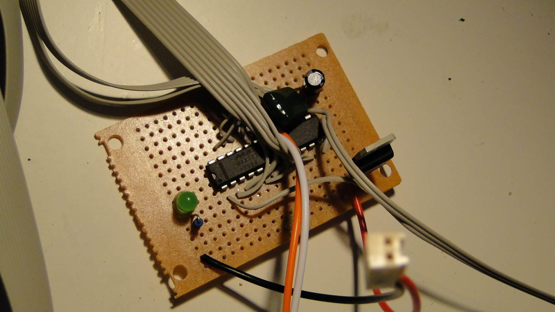
The functional dog's breakfast... This is a tiny piece of veroboard with 4 H-Bridges (8 outputs) and an LM7805 to provide the +5v. The inputs on the H-Bridges are chained together and the enable pins (8 of them) run to one side of the CD4514BC.
Here is the CD4514BC Multiplexer. This receives 6 wires from the Arduino and then outputs 16 digital to whatever I require.
And everything working in concert.
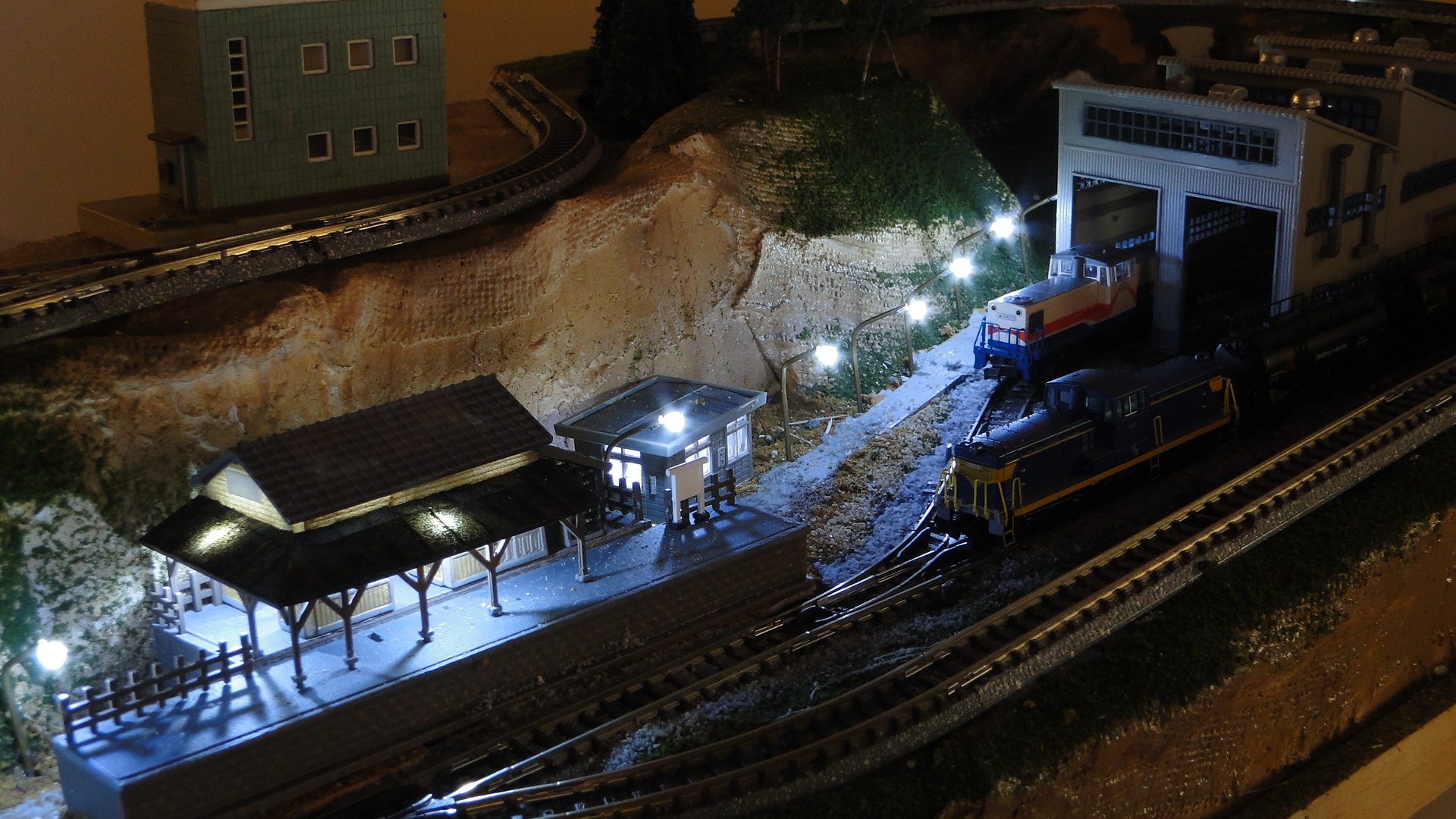
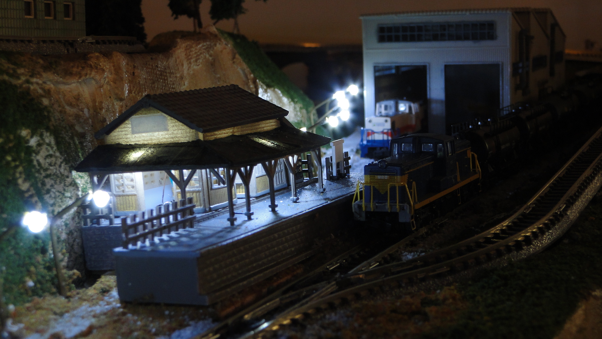
Random Photos
Search
Tags
Links - Click for details
- Abandoned Rails (Japan)
- AIRLINE (Shinkansen Photography)
- Akihabara Station
- annexpressのブログ
- Australian Model Railway Magazine
- DCC普及協会ホームページ (Japanese DCC)
- Dead Section (Japanese Track Diagrams)
- Delicious Things (Japanese N Scale DCC)
- Densha Wotorou
- Digital Direct for Windows (DCC Server)
- Don's Dream World – AMAZING N Scale Japanese Layout
- Hatena::Diary
- Japanese N-Scale Modeling Forum
- JR Chiisai
- Kaz-T's blog レインボーライン (Rainbow Line)
- LED Resitance Calculator
- Masioka
- Poppondetta Blog
- RailFan Magazine, Japan
- Railmind
- Railway Travelers' Room
- Serenity Valley
- Shashinka Ichiban
- Shuzuku
- Sumida Crossing
- The next station is…
- Tomix N Gauge Track and Japanese N Gauge Trains
- TT Forums (Transport Tycoon Deluxe)
- 名鉄尾西線の貨物列車 (Nagoya: Meitetsu Freight)
- 日本型Nゲージ DCC改造例のご紹介 (Okiraku DCC)
- 泰 茅 轍 道 (Taichi Railway)
- 箱庭登山鉄道製作記 (Hakone-Tozan Layout Blog)
Archive
- July 2026
- May 2026
- April 2026
- March 2026
- February 2026
- January 2026
- November 2025
- October 2025
- September 2025
- August 2025
- July 2025
- June 2025
- February 2025
- January 2025
- November 2024
- September 2024
- August 2024
- July 2024
- June 2024
- May 2024
- April 2024
- March 2024
- February 2024
- December 2023
- October 2023
- September 2023
- August 2023
- July 2023
- June 2023
- May 2023
- April 2023
- March 2023
- December 2022
- November 2022
- October 2022
- April 2022
- March 2022
- February 2022
- January 2022
- December 2021
- November 2021
- September 2021
- August 2021
- July 2021
- May 2021
- March 2021
- February 2021
- January 2021
- October 2020
- September 2020
- August 2020
- July 2020
- June 2020
- May 2020
- April 2020
- March 2020
- January 2020
- December 2019
- November 2019
- October 2019
- September 2019
- August 2019
- July 2019
- June 2019
- April 2019
- March 2019
- February 2019
- January 2019
- December 2018
- November 2018
- October 2018
- September 2018
- August 2018
- July 2018
- June 2018
- May 2018
- April 2018
- March 2018
- January 2018
- December 2017
- November 2017
- October 2017
- September 2017
- August 2017
- July 2017
- June 2017
- May 2017
- March 2017
- February 2017
- January 2017
- December 2016
- November 2016
- October 2016
- September 2016
- August 2016
- July 2016
- June 2016
- May 2016
- February 2016
- November 2015
- October 2015
- September 2015
- August 2015
- July 2015
- June 2015
- May 2015
- April 2015
- March 2015
- February 2015
- January 2015
- December 2014
- November 2014
- August 2014
- July 2014
- May 2014
- April 2014
- March 2014
- December 2013
- November 2013
- October 2013
- June 2013
- August 2012
- April 2012
- March 2012
- February 2012
- November 2011
- October 2011
- September 2011
- July 2011
- June 2011
- May 2011
- April 2011
- March 2011
- February 2011
- January 2011
- December 2010
- November 2010
- October 2010
- September 2010
- August 2010
- June 2010
- May 2010
- April 2010
- March 2010
- February 2010
- January 2010
- December 2009
- November 2009
- October 2009
- August 2009
- January 2009
- December 2008
- November 2008
- October 2008
- September 2008
- July 2008