


 Melbourne BG SCS Train Timetable


Model Railway Shops in Osaka
To make the guesswork easier, here's a list of terms that should help you on your never-ending-search-to-find-model-trains. To translate things, use Google Translate. To convert from Romaji, Hiragana, Katakana or Kanji use J-Talk's Kanji Converter
| English | Romaji | Hiragana | Kanji |
|---|---|---|---|
| Train | resshya | れっしゃ | 列車 |
| Electric Train | denshya | でんしゃ | 電車 |
| Steam Train | kishya | きしゃ | 汽車 |
| Diesel Train | kidoushya | きどうしゃ | 気動車 |
| Model | mokei | もけい | 模型 |
| Model Train | mokei resshya | もけい れっしゃ | 模型列車 |
| Railway Model | tetsudou mokei | てつどう もけい | 鉄道模型 |
| Gauge | geeji | ゲージ | -- |
| Shop | shoppu/mise | ショップ/みせ | 店 |
| ?-Shop | ?-ya | や | ?-屋 |
Den Den Town, Osaka
One of the most well-known Osaka hobby shops. A place you simply must visit. Has everything.
(Note that their Tsurumi shop is closed!)
Super Kids Land (スーパーキッズランド本店)
A large toy department store with a floor dedicated to model railways. A good selection of HO-scale too!
A cute little shop with a good selection of consists. Also a good bargain-bin for second-hand items. Note that they will be graded from A-D where D is quite broken!
Volks Osaka Showroom(ボークス 大阪ショールーム)
Another toy department store; you'll find the trains on level 6.
Shinsekai
Rail Workshop Higeshin (レール工房ひげしん)
A small store on the north-west corner of Shinsekai. I walked in and couldn't communicate, but there's glass cabinets of nice stock, both N and HO. The owner is usually there building models as well. Seems to have a 'club' atmosphere with regulars often hanging around to chat to the owner.
Note that Shinsekai is a relic of Osaka, planned/built as the 'suburb of the future' back from 1903.
Address: 大阪市浪速区恵美須東1-22-1
Uehommachi (East Osaka)
There's a good story behind this shop. I visited it in 2010 with a friend from university; her uncle actually works there. Back then the shop was south-east of Kintetsu Osakauehonmachi Station and it was a confusing walk from the station to get to it. The shop was small, full of glass cabinets and cutting boards. It had a great selection of N-scale and HO, specialising in paper kits. I remember that there were a lot of full N-scale sets, some 'custom made' and painted to prototypical awesomeness. I bought a DE10 and a set of passenger cars, beautifully detailed.
The shop has now moved here and, although I haven't been back since it moved, it seems to be a bigger and better presence with full layouts for demonstrations. It also seems a lot easier to get to!
Umeda
Haven't been to this one, but can only imagine it's just like its brother in Den Den Town.
Another department store... trains are on B2. I always end up going here since it's so close to Osaka Station and I can send my friends to other levels if they don't want to check out trains.
This shop actually seems to be pronounced ma-ha mokei; but for some reason they've translated that to 'mach'.
Minamikata
Someone go and check this place out!
Awaza
Review to come....
Hanakawa (North-East)
Haven't been to this one, but can only imagine it's just like its brothers.
Toyonaka (North)
Review to come....
Takastuki
Recycle Shop (Ryouhin Kaikan) (HobbyDo!) ![]()
I accidently stumbled across this shop. I'd bought a bike for my 4-week stay in Shinosaka and had been riding east towards Kyoto. The Tokaido main line and Shinkansen are both out that way and can be seen up quite close. Anyway, this shop is walking distance from JR Takatsuki Station, but closer to Hankyu Takatsuki-shi Station. Head due-east from either and then north-east along 国道171号線 (Japan National Route 171).
The shop has a great selection of new and second hand goods. I especially loved rummaging through the box of B-Train Shorty odds-and-ends. It seems that they had many split up boxes of B-Trains and each component is individually priced. Just remember, when you get to the counter things always add up!
Matsubara
Mokei-ya (Model Shop) (もけいや松原) ![]()
From the website, this place seems to have a lot of stock. Has anyone been!?
Kobe
(This used to be in Amagasaki, but that closed)
庫県神戸市東灘区青木1-2-34 サンシャインワーフ神戸1F
Haven't been to this one, but can only imagine it's just like its brothers in Den Den Town and Umeda.
2 Chome Sannomiyacho, Chuo Ward, Kobe, Hyogo Prefecture, Japan.
Table Railway – Continued
It's been green for a while.. but I thought I might as well provide a long-overdue update. The table layout has received a fresh coating of grass and it's in quite a reasonable state after moving house. It coped with being held upright through doorways and thrown around in the back of a car... so it seems my process of painting, gluing and spraying ballast and foliage worked well.
Painting the base scenery
The last thing one needs is white plaster showing through the scenery base. It really does ruin all of your hard work very quickly. To prevent this I coated the entire base with an appropriately-coloured paint. Japan's scenery is ultra-lush, so a dark green here will work well.
Adding the grass
Adding grass to the green paint brings it to life. Texture is the key here and un-even-ness is to be achieved. Don't be scared to glue layer upon layer upon layer. I've used a glue/water ratio of around 3-10 to make sure everything sticks. It's a little thicker than you'll need for a layout that won't be thrown around as much as this one will.
Sinking and Ballasting the track
I'd done this before on my previous railway and the effect is much more realistic. Although the plastic ballast that comes with Unitrack isn't ugly, it easily removes from the realism of a layout. To get around this I've cut a trench for the track and glued ballast down the sides. Be careful not to completely cover the track with glue...
The best part? My 300 Series Shinkansen bolted round the loops at full-tilt... I really wasn't expecting it to cope. It's about time to add a city.
Yet another layout…
It was about time to fill the table I'd bought from an op-shop a long time ago. I'd attempted a layout for this prior using the Arduino and CAN Bus to control it... but I somehow lost interest and demolished it. Hence we begin with the 810mm(Squared) Table Layout Version 2.0.
The space was relatively small and, thanks to my previous attempt, I knew there wasn't going to be much more than a loop-the-loop. The whole reason for building this was to run my 300 Series Shinkasen and that meant wide curves and wide clearances. For some reason I then decided that a loop-the-loop was boring and that I could fit a loop-the-loop-the-loop in.
I set to work on Anyrail.Net and found that a triple-loop was going to be tight. Unitrack had enough different radii curves to get the loops in, but I'd have to be using the tightest available... not too good for a 7-car Shinkansen. So... I started breaking the mould and making everything not-quite-fit together in the layout software. This meant slightly wider curves but potentially dangerous track joins where I would be 'stretching' the limits of unitrack to fit. Fortunately it turns out to be pretty forgiving.
I went to a not-so-local hobby store and found they had a HUGE selection of Japanese stock. I had my list printed from Anyrail and went about collecting. I also got some Walthers gradient foam for my crazy layout.
After a little fiddling the track was laid out and temporarily elevated into place. It all worked... but was a squeeze. With nothing stuck down you'd attempt to get track to connect in one spot and it'd fall out of alignment in another... I don't really recommend jamming Unitrack together in odd formations!
The result was a successful session of test running with all of the stock I could find!
Kato Unitrack vs. Moisture/Humidity from setting plaster
It probably should've been obvious, but I've just found out the hard way of the effects of drying plaster (Woodland Scenics Plaster Cloth) and Kato Unitrack when kept in a small enclosed space.
I've been building a new layout recently in a coffee table I acquired from a secondhand store. It's around 80x80cm and fits a nice loop-the-loop-the-loop layout.
After planning and purchasing the track, I started to build up the scenery. Once the foam was down, the plaster was laid. Due to wanting to be neat, I returned the setting/drying scenery back into the table each night to dry. I noticed on the second day that the plaster hadn't really dried that much, so I chose not to run any locos (there had been a C50 steamer sitting in the table overnight too!.)
The next day I then noticed that the track had a strange tinge to it. I attempted to run the steamer, but the performance was terrible (although this was second hand and hadn't run 100% in the first place.) Another locomotive didn't do much better.
The cause was obvious on closer inspection...
(First image: notice that left track is shiny and right is dull. Second image: see mould.)
After 'phoning a friend' on the JNS Forums, a few possible options came up... the most probably one being the chemicals used in the plaster cloth. These could well have hung around inside the glass table whilst the plaster was drying and adversely affected the track.
I'm still in the process of cleaning it all up (a quick once-over with a cleaning block worked fine)... the sides of the rails are still tarnished. Currently alcohol-wipes are doing the best job of cleaning this mess up!
Lighting a Japanese Temple
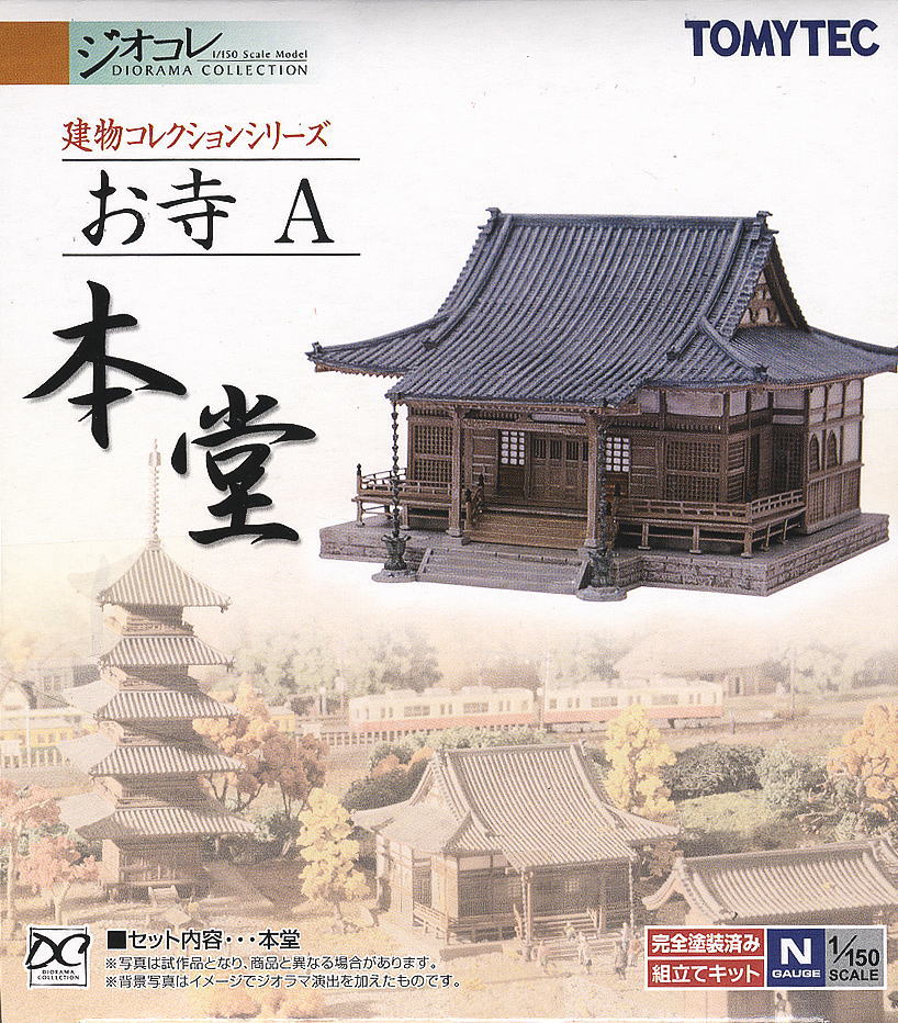
I'd decided it was time to light the temple after building the Torii for the entrance. This temple was the Tomytec Japanese Temple A (Main Building) and is still available for purchase from most Japanese online hobby retailers.
I've slapped LEDs in buildings before, but this time I also wanted to add lanterns to the front of the shop. I'd made the lanterns before, as in my previous attempts of creating the Torii, but I was to make a few changes this time as I wasn't totally impressed with the previous outcome.
Creating the lanterns
There was a slight change this time to creating the lanterns... instead of cutting them and sliding them over the LEDs, I shaved them down to fit and inserted them into the center of the tubing. This all worked well, but you must be careful when shaving down the LEDs as you can destroy them quite easily. To shave the LEDs, I held them in pliers in one hand and filed away with my pocket knife. It was pretty obvious to feel when you were no longer filing away at plastic and, unfortunately, this was usually the demise of the LED.
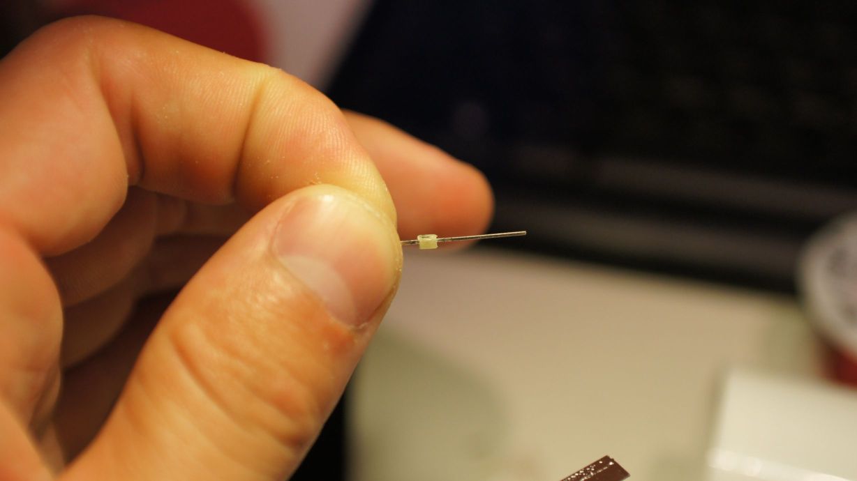

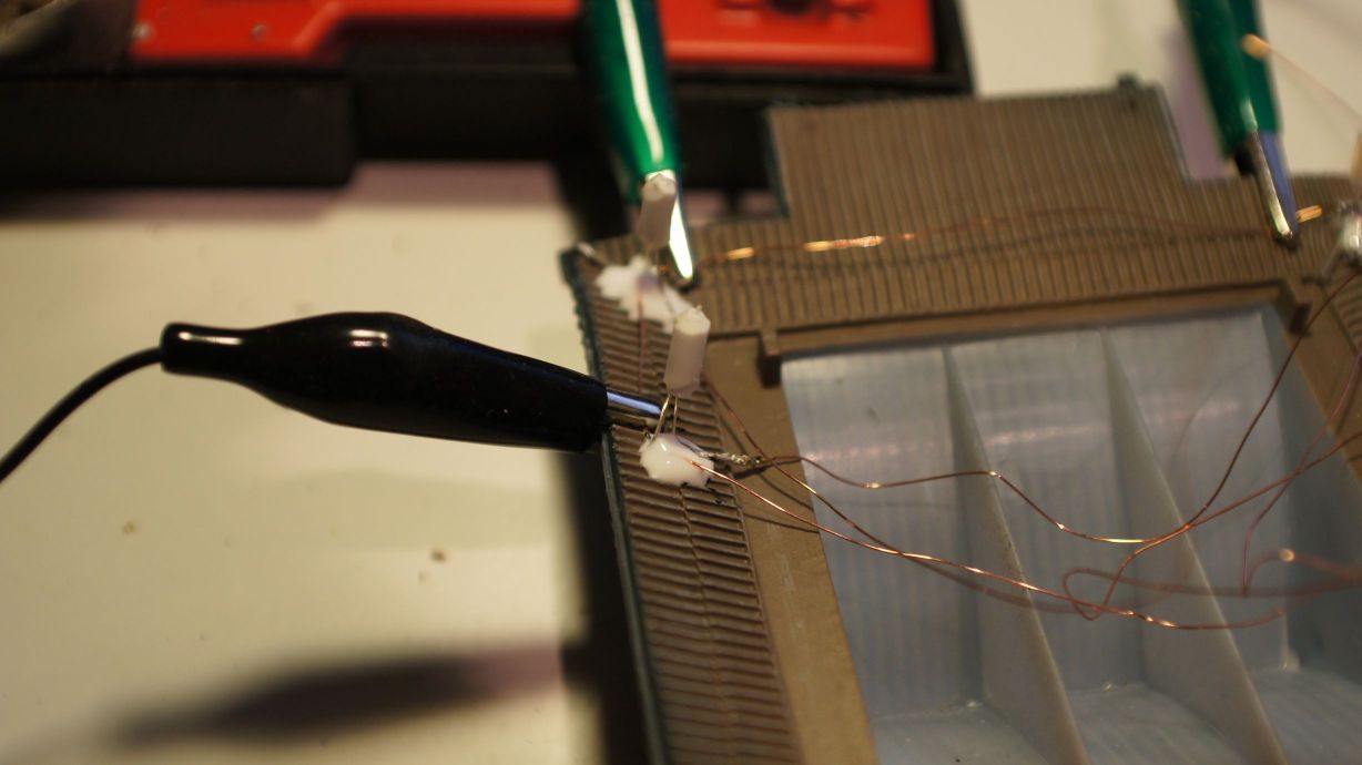
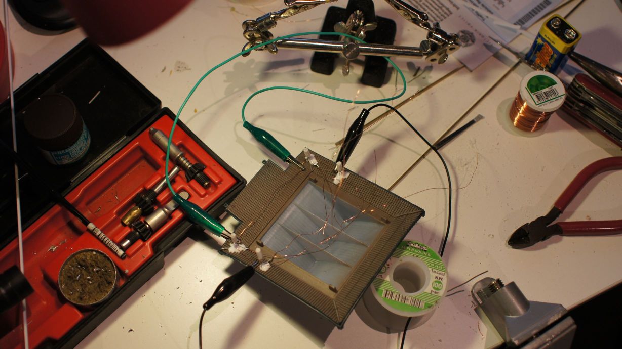
Mounting the lanterns
I used the same copper winding wire that I always do and bent it into a rectangular shape to fit the roof of the temple. I then started soldering the lanterns in place.
I then pulled out the trusty Selleys Aquadere and, using random aligator clips found on the bench, glued the lanterns in place.
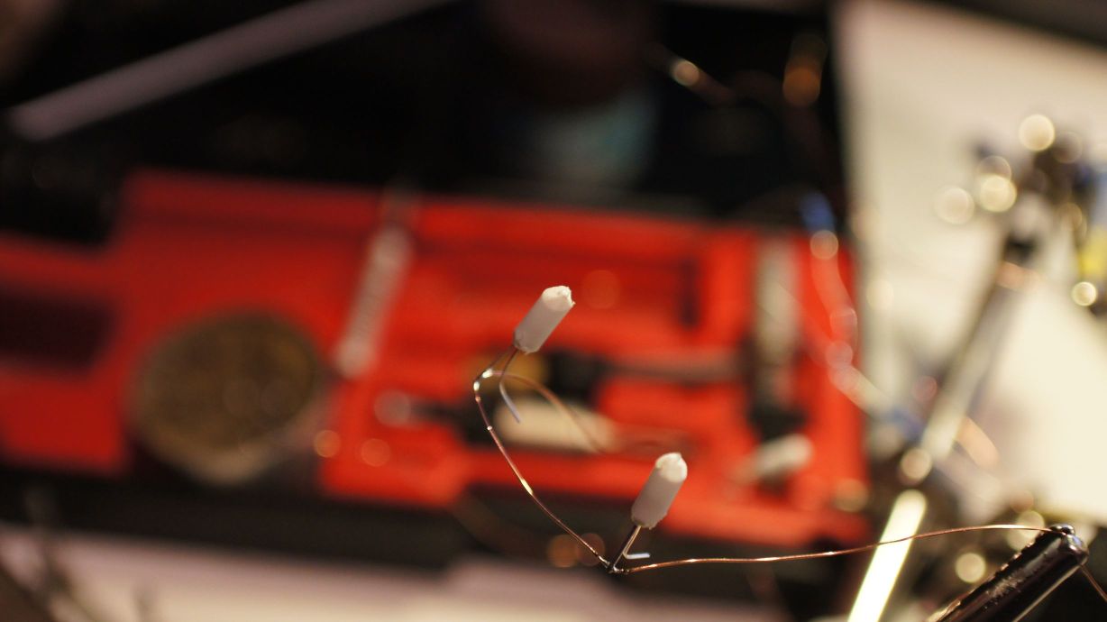
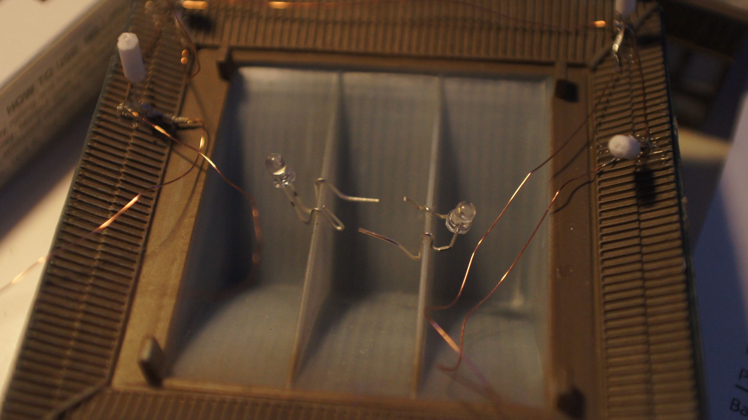
I also put two standard 3mm white LEDs in the center of the ceiling for building lights.
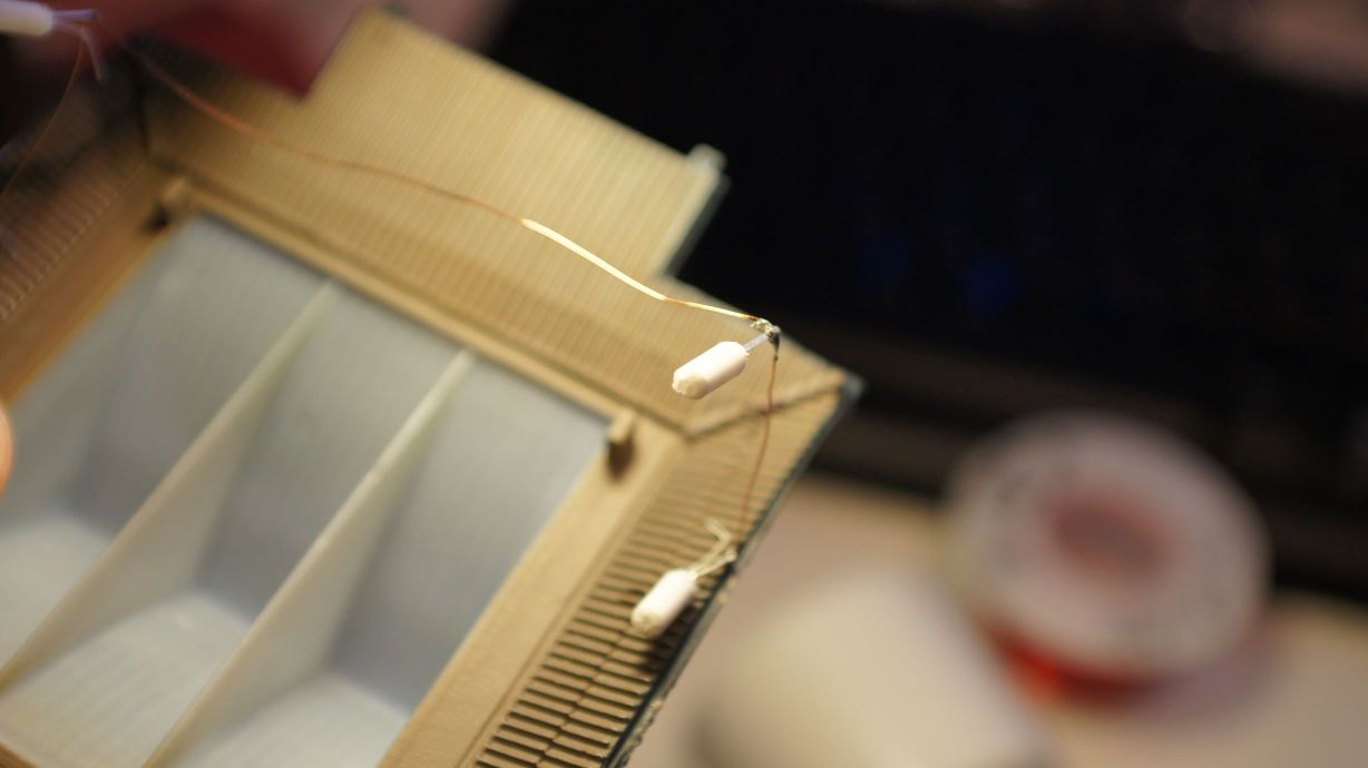
The finished product
After the glue had dried, I tested all the LEDs and found that I'd broken the front-left lantern. This was 24hours after starting the project and frustrating. I quickly removed it from the temple and filed another LED down. I left it dry again, overnight, after testing, gluing and testing again.
Finally, yesterday, I was able to hook it up to my Arduino LED Controller. It worked perfectly and I took the opportunity to test my night-time photography skills.
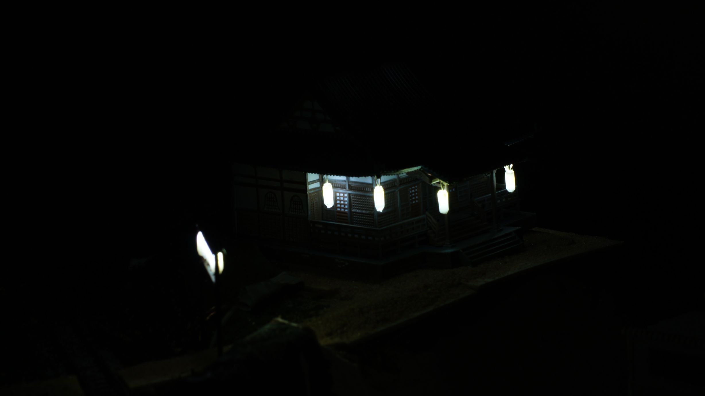
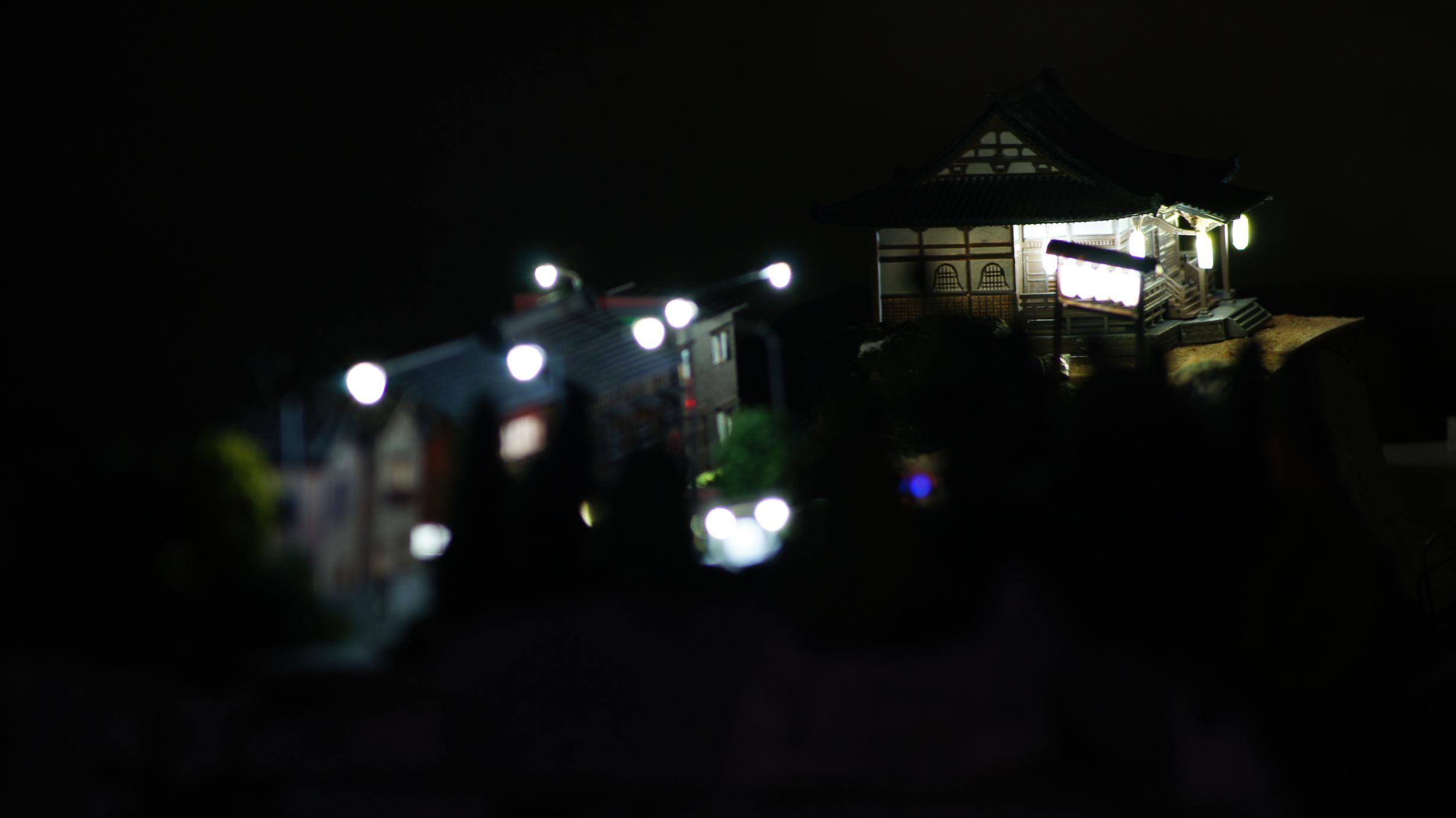
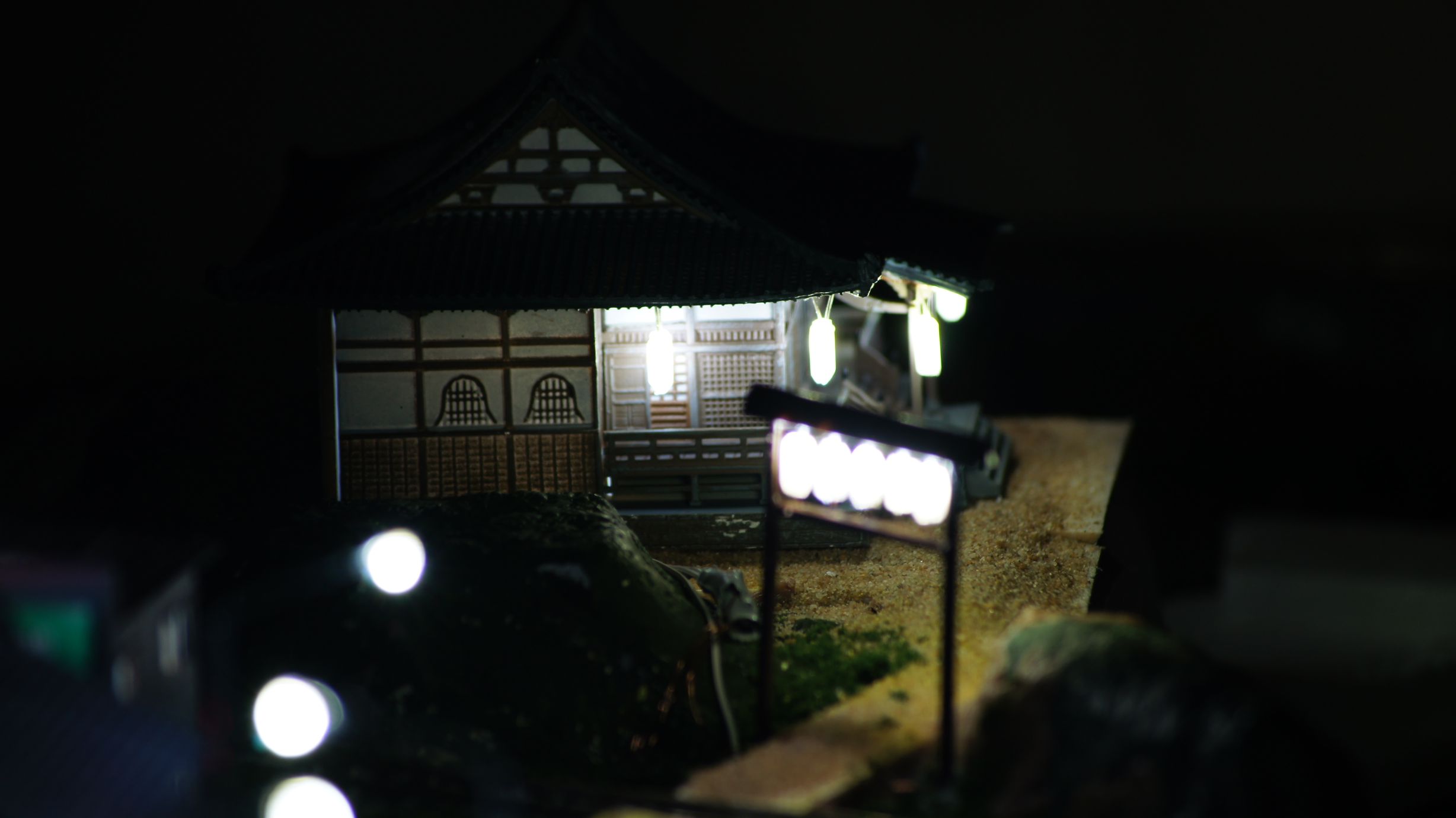
Now to settle the landscape around it.
Creating a Shrine Torii Entrance
After checking out more of the work by tanaka_ace on the Tounosawa Blog, I've decided to add a Japanese Shrine to my layout. I've extended the upper level to allow room for a kit I bought in Japan last September and have created a path back to the main town area.
As with any Shrine in Japan, the grounds are seen as sacred and insulated from the surrounding area; usually by either high walls or thick vegetation with a Torii gate for the entrance. I'll be adding the walls in soon enough, but prior to doing so I wanted to make sure I had all of the buildings and scenery effects in place.
The first thing to create was the Torii gate entrance. Tanaka_ace on his Tounosawa Blog had created a very nice gate with LED lanterns added. This is all based off a real-life location at the Tounosawa Station on the Hakone Tozan Railway. He had also created a blog post showing what he based the model off.
My version
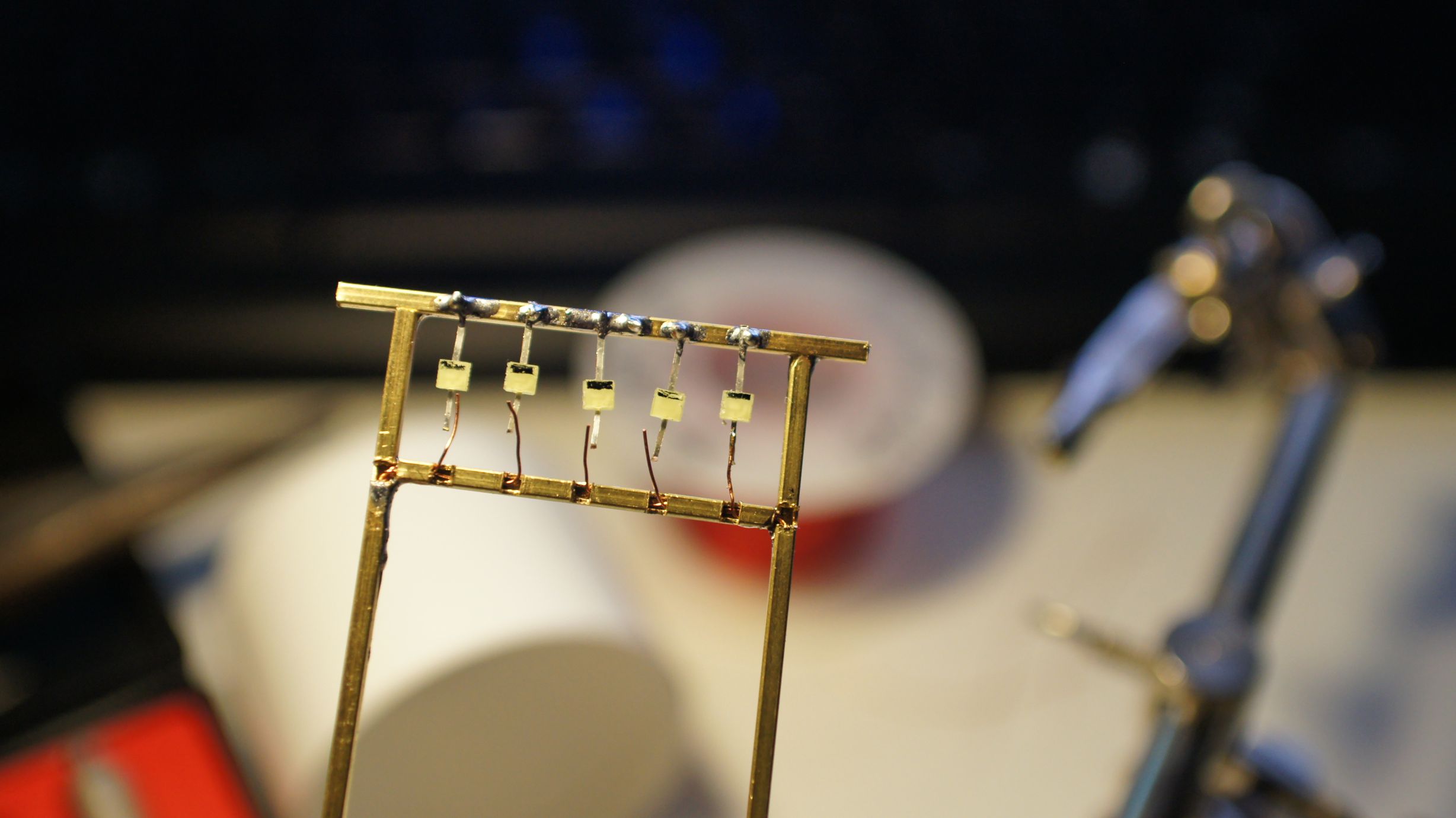
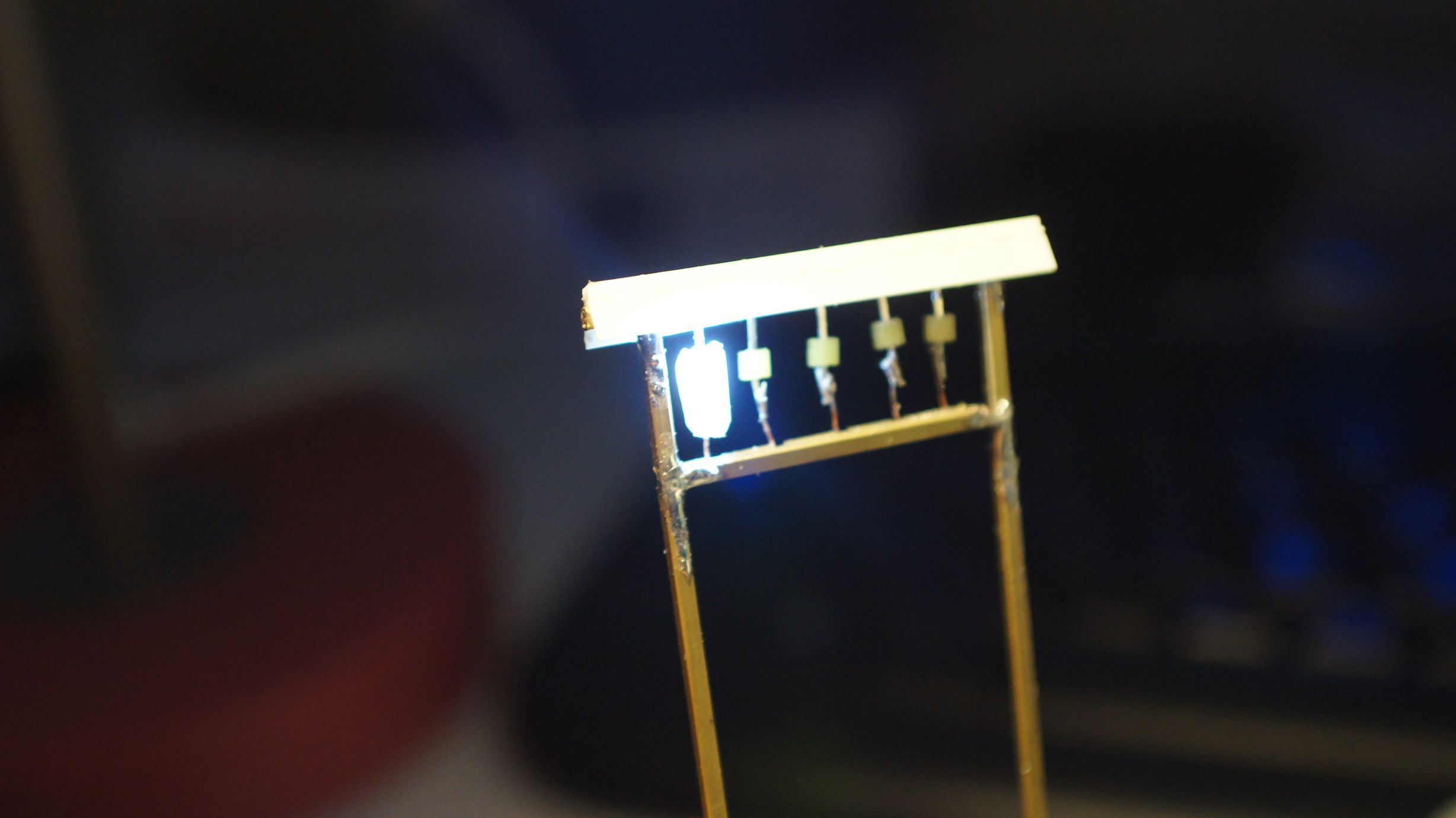
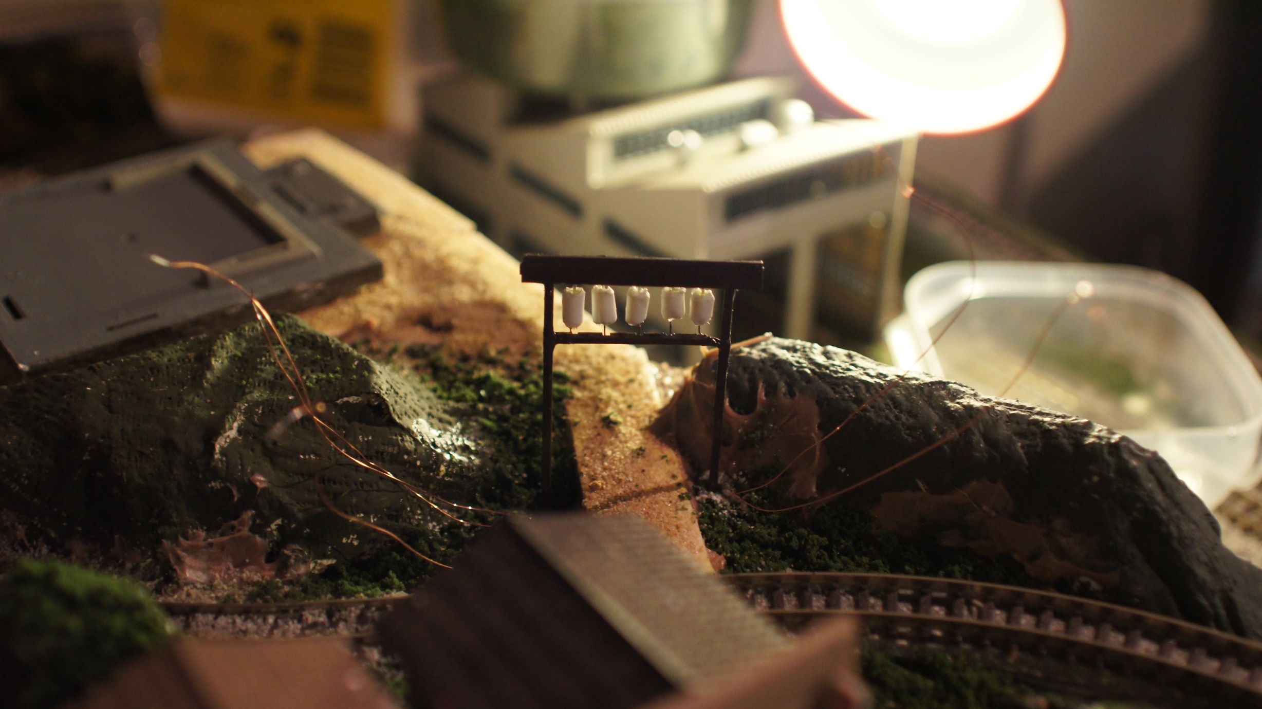
I've used the same gauge winding wire I'd used for my level crossing lights, streetlights and building lighting. With this I've also used 1/16" brass pole for the main frame of the gate because I wanted to emulate wood rather than a cylindrical concrete post this time. This also provided a little more room to squeeze the wires through. Each length needed to be cut down to size and then filed back. I used standard snips to cut the brass, a smaller saw would've been a better idea.


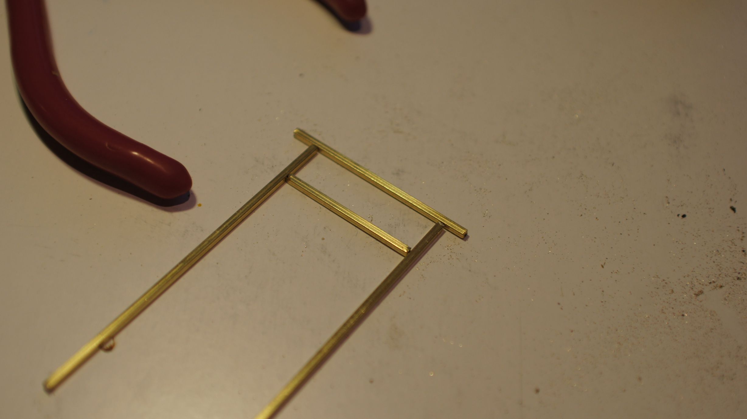
I based the size on the path that I had already created on the layout. I didn't really have a real-life prototype to work off and made a lot of it up as I went. The final size was around 50mm wide and I could fit 5 lanterns in. Below you can see the framing taking place.
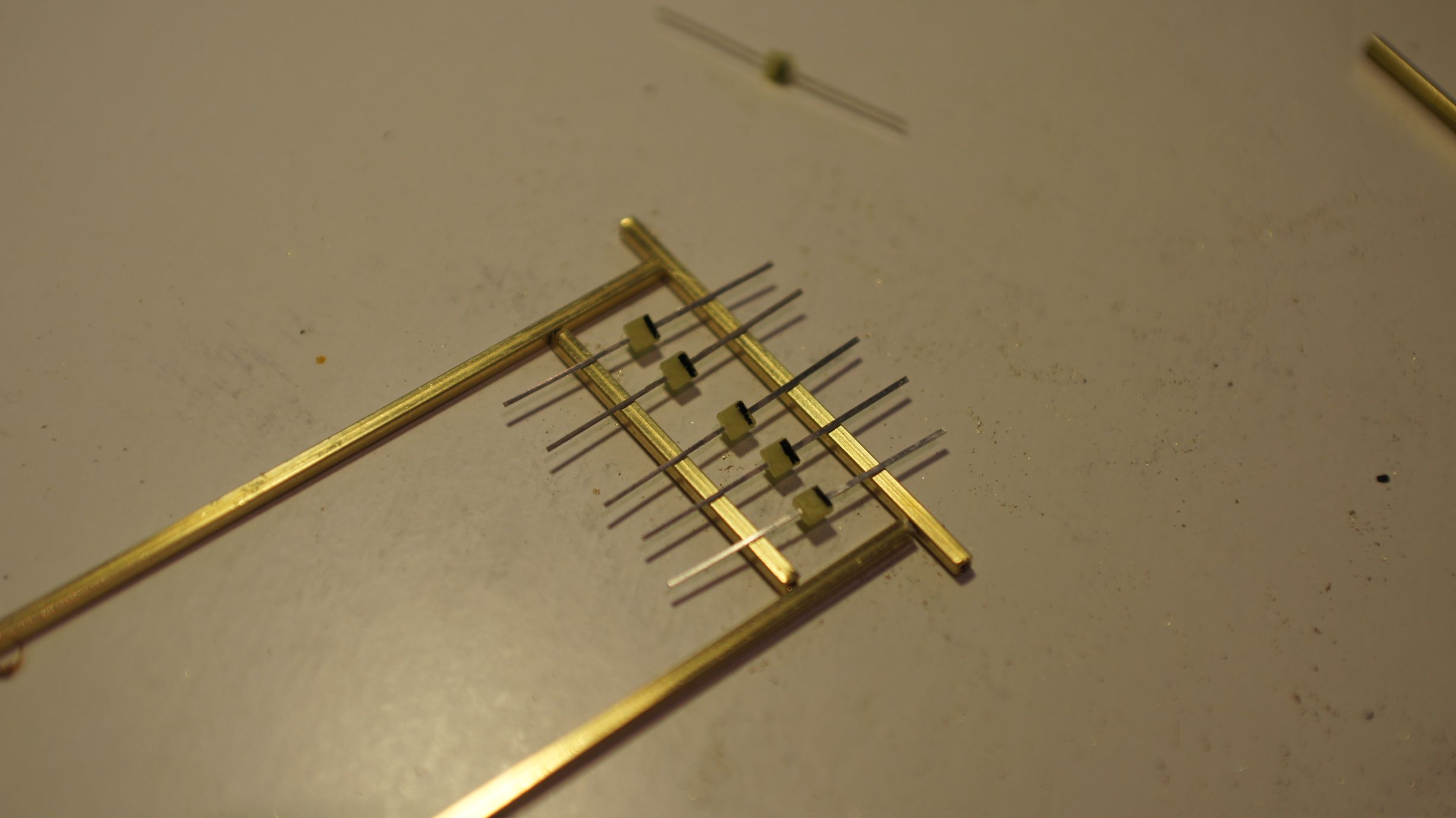
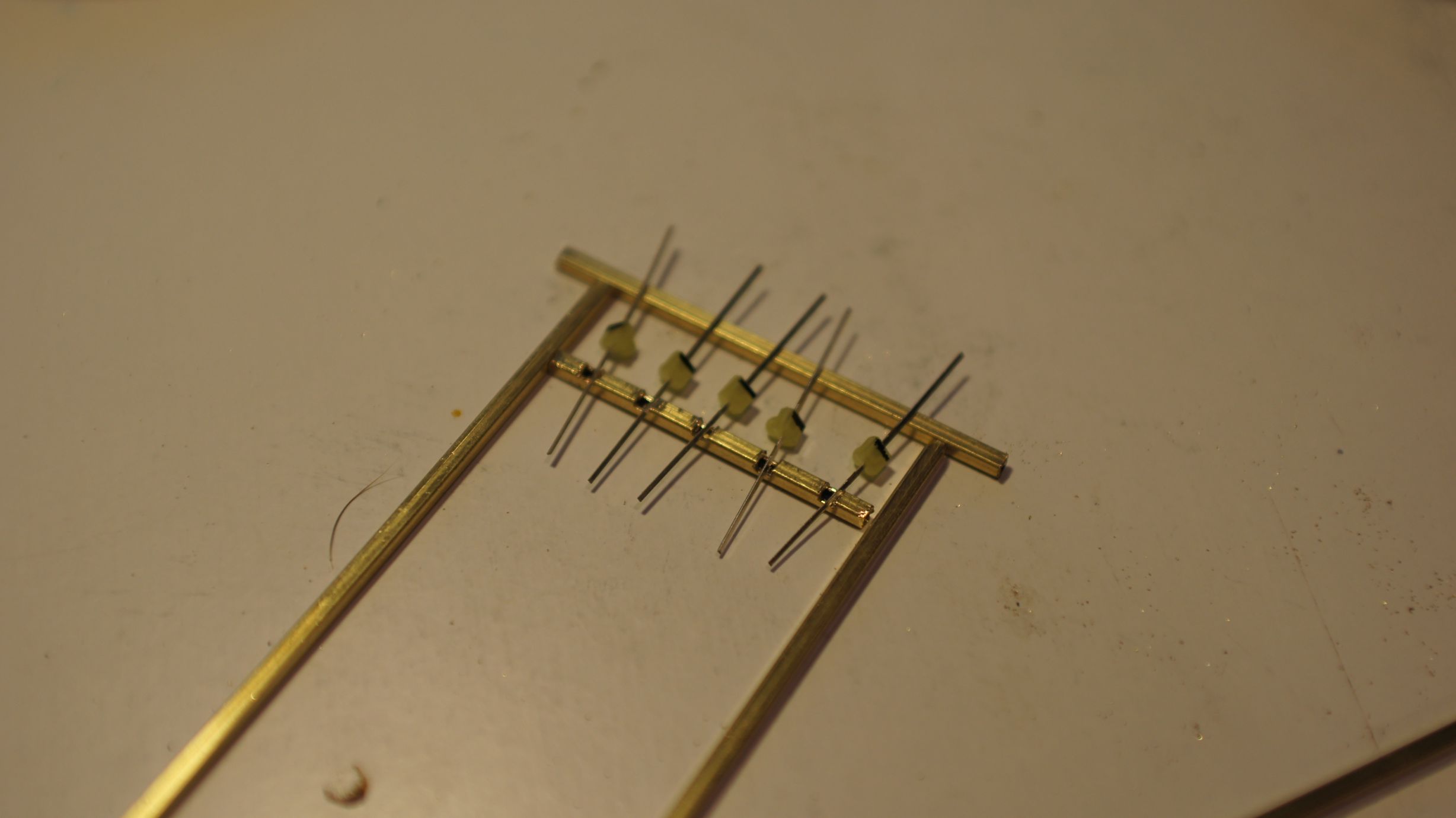
I then started cutting out the holes to feed the wire through. I used my trusty pocket-knife as the brass was quite soft. I also used a wire cut off a resistor to clean out the tubes of any metal shavings. The entrances created for the wires would have sharp edges and could scrape off the insulation on the wires, so I made the holes as big as possible.
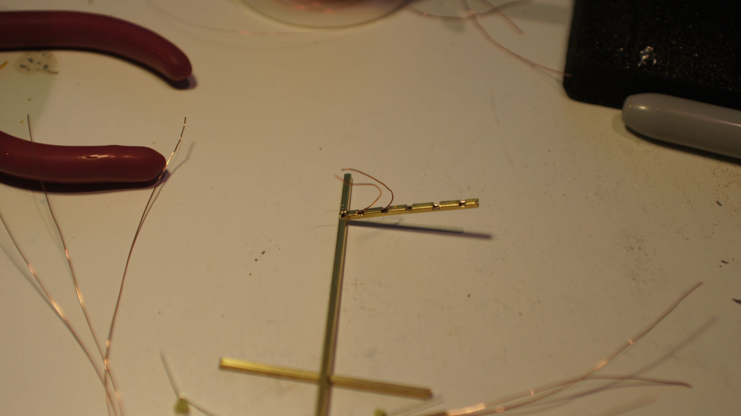
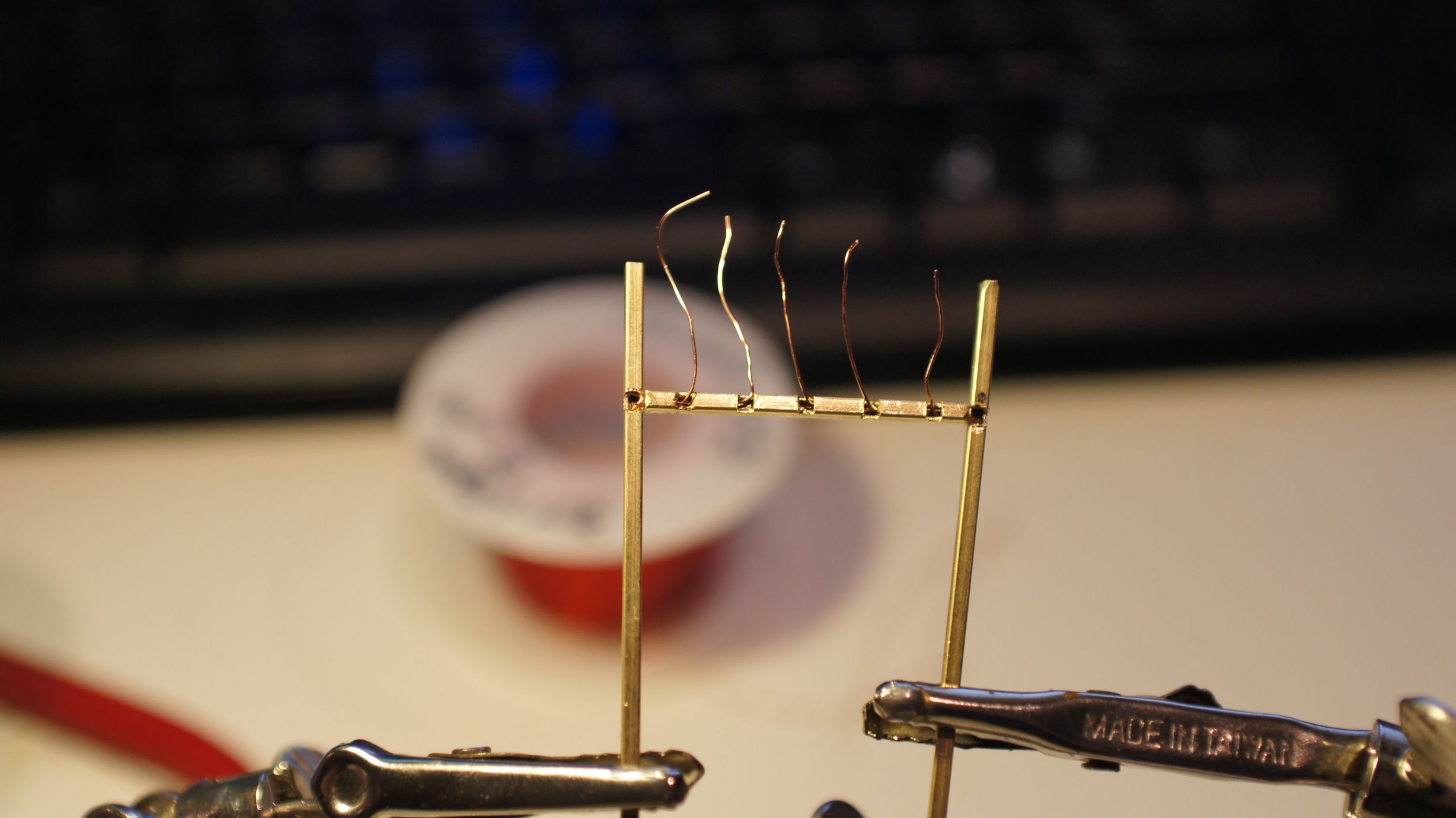
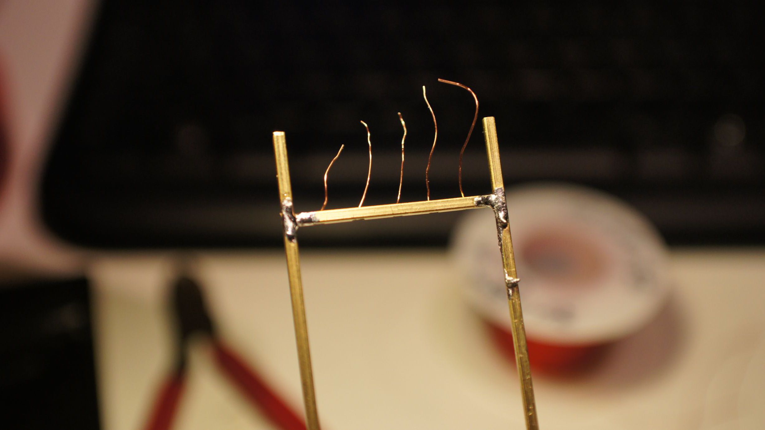
Once the holes were cut, I fed the wires through as a test. I then constructed the frame with solder. At this point I accidently overheated the wires on the left side. This caused one to ground and I then couldn't successfully light 1 of the 5 LEDs. I took more care the second time around when soldering the frame back together.
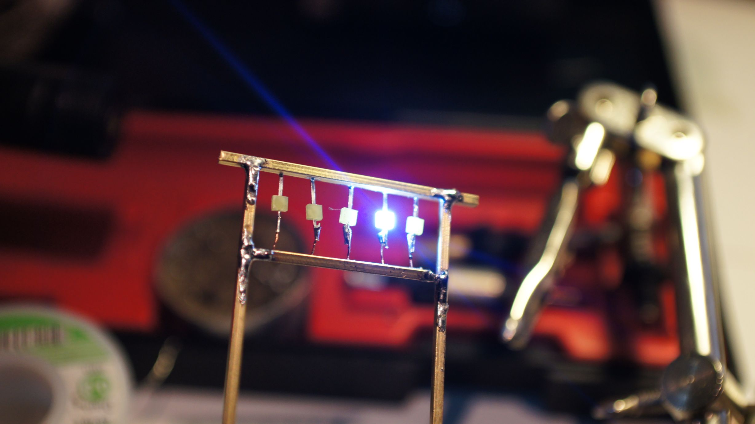
I added a quick roof to the frame as tanaka_ace had done with his second version.

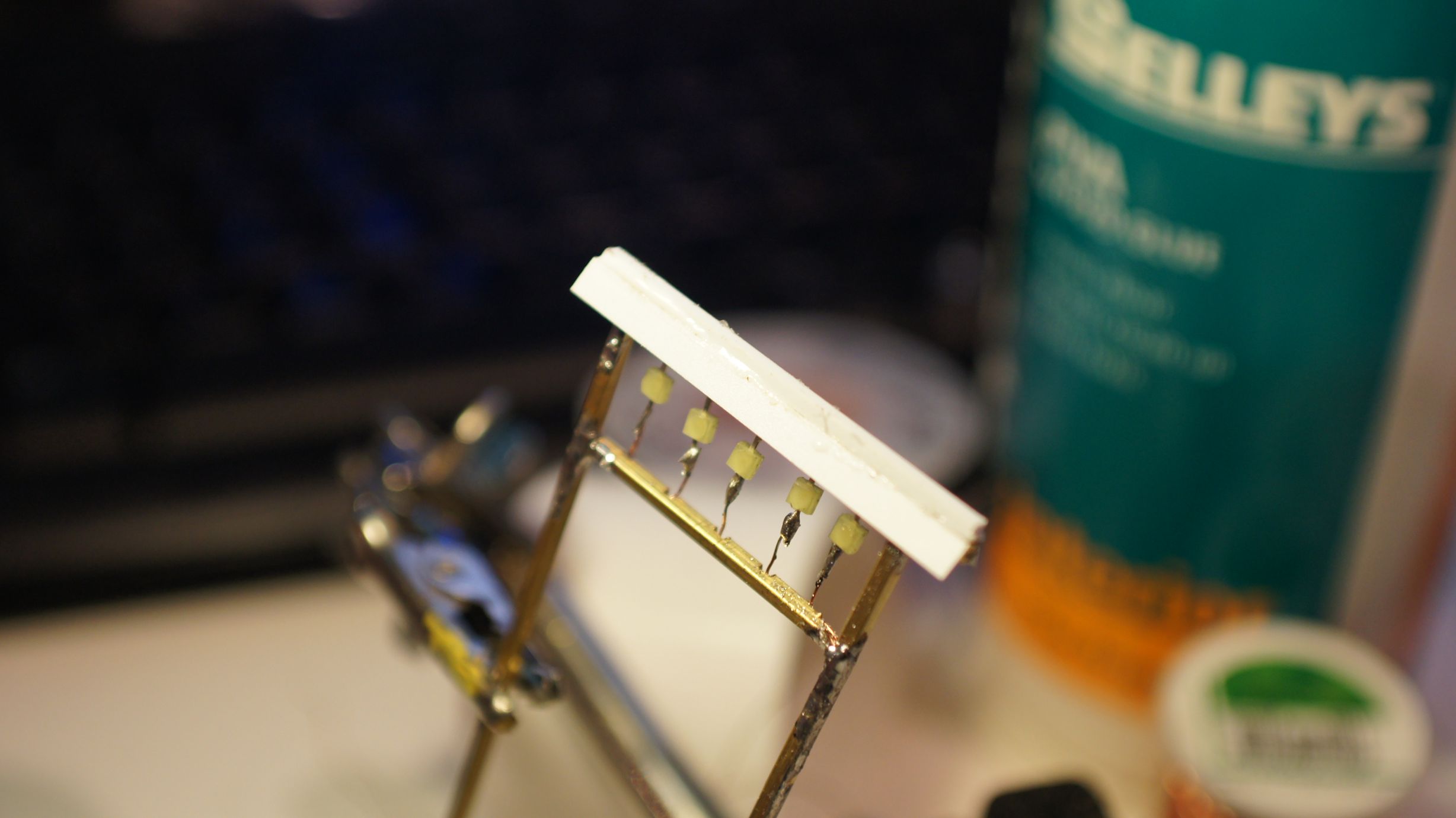
Now that the frame and LEDs were in place, I could go about turning them into lanterns. This would be done by putting plastic piping around them. I had already done this with a fixed lantern on a TomyTec Japanese Shop, but this time I had no existing lanterns to work with. I therefore used the same concept as tanaka_ace.
Thanks to globalisation, I was able to acquire the exact same "Evergreen Scale Models" poly-piping that he used. I happened to purchase 3.2mm pipe instead of the 2.4mm; but this worked out well as the LEDs that I was using were a little bigger. The pipe was cut into appropriate lengths and then the edges rounded down to create the lantern shape. The individual lanterns were then sliced at the back so that I could slide them over the LEDs. I then used stock-standard Shelleys Aquadhere to fill in the ends.
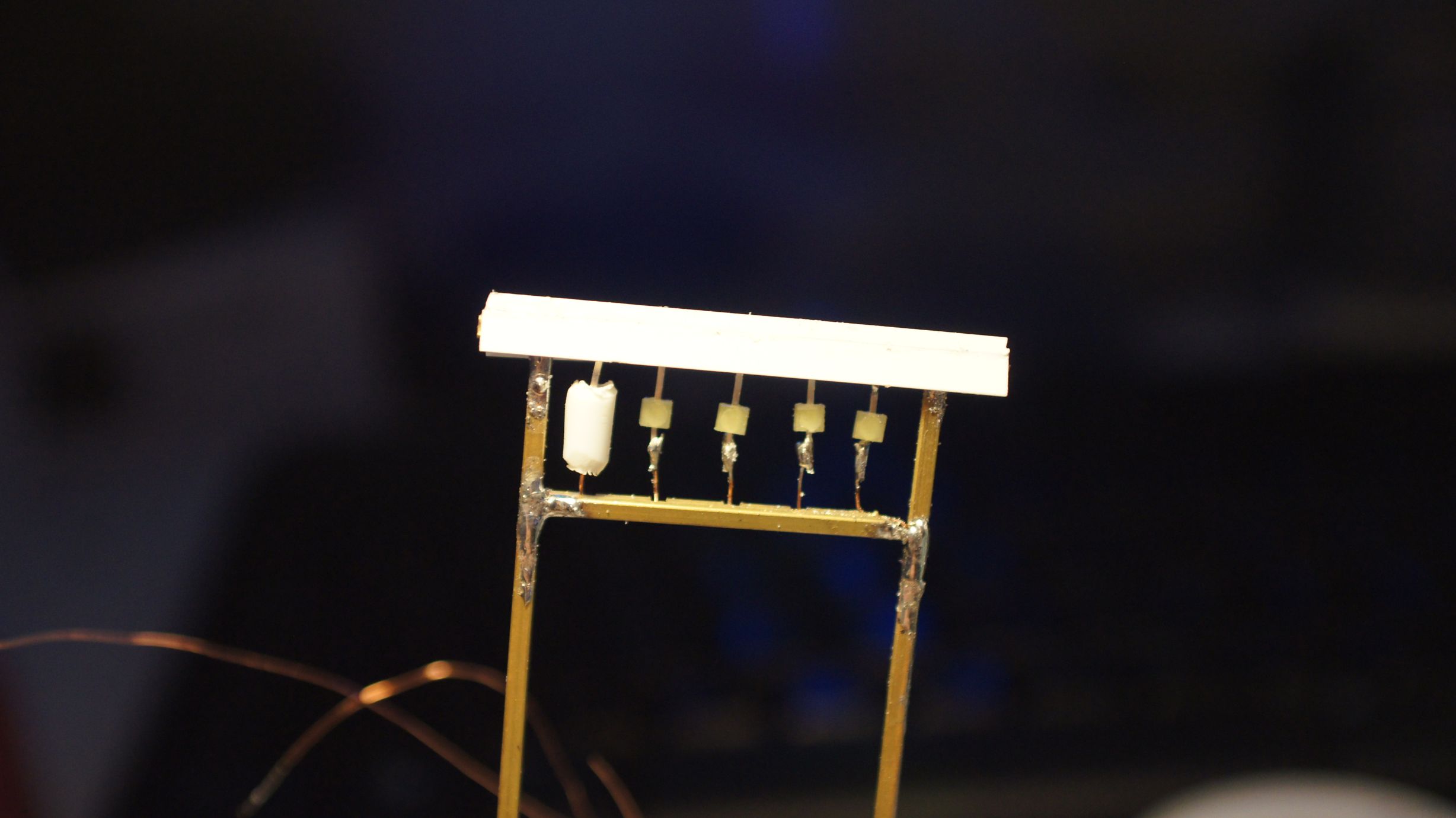
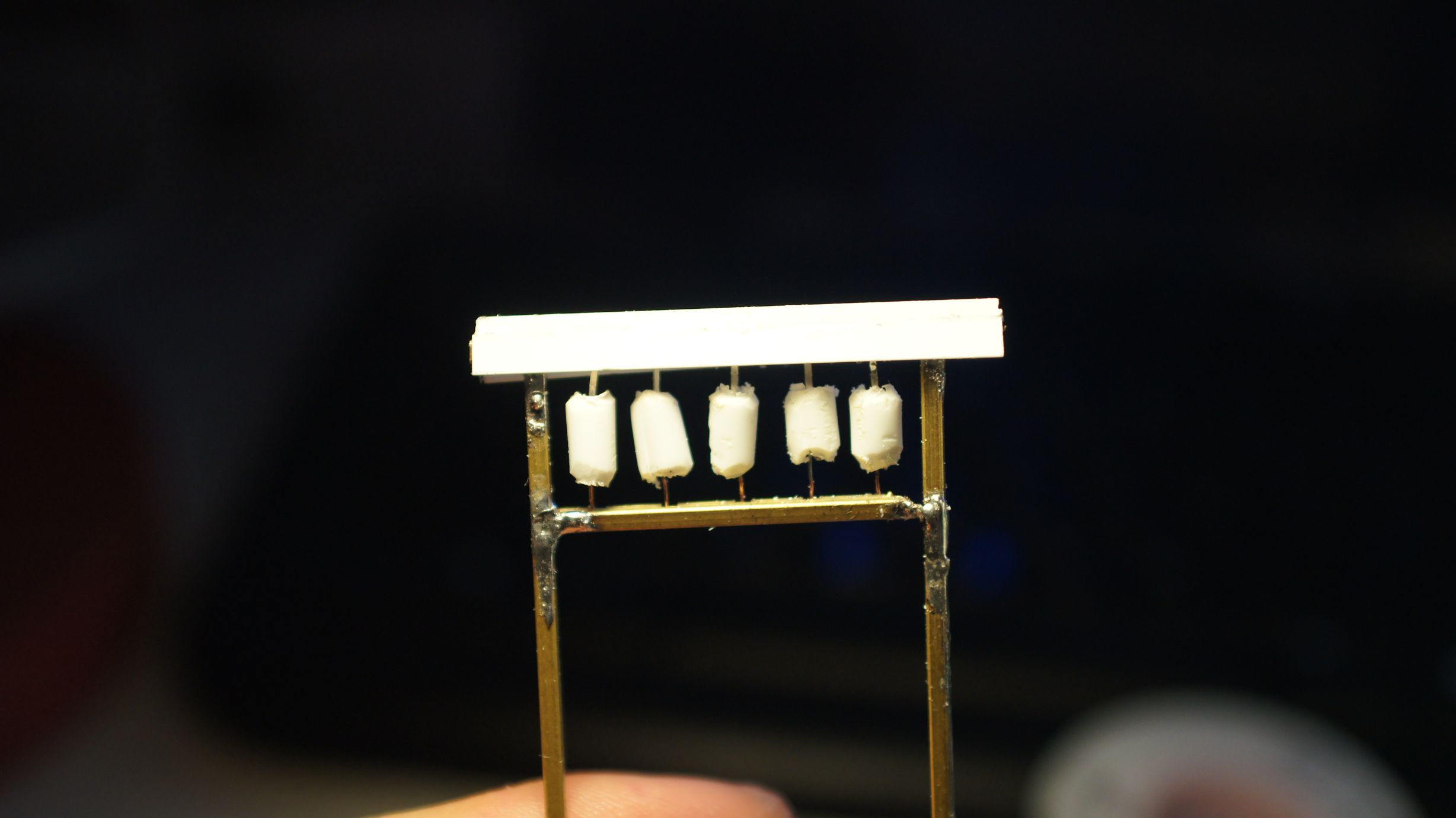
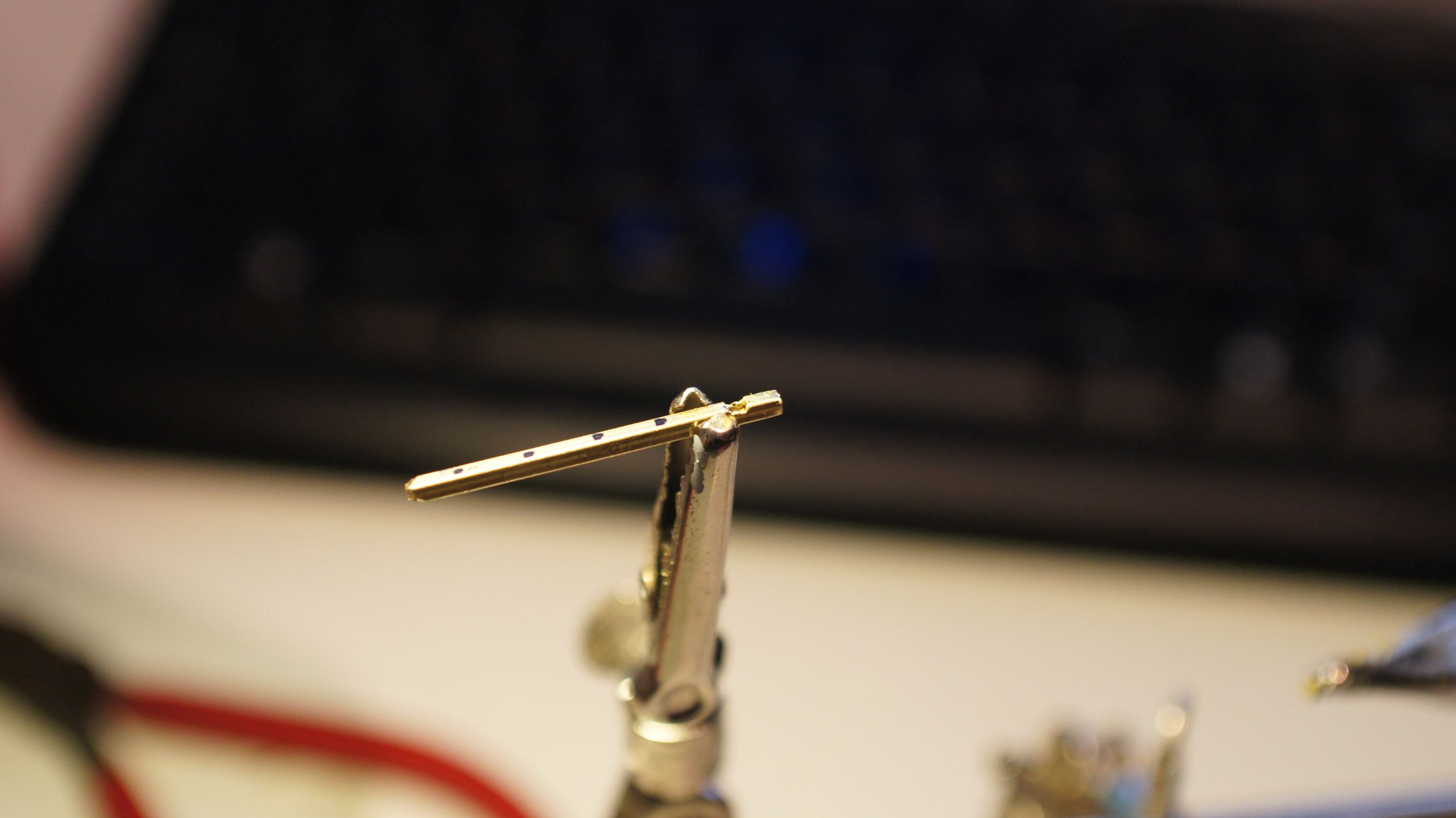
Once these were holding in place, I painted the frame a nice wood-brown. Torii gates can be made of wood or stone and painted a multitude of colours. You more often than not will see them in brown wood, but bright red, and even out in the ocean, is not uncommon.
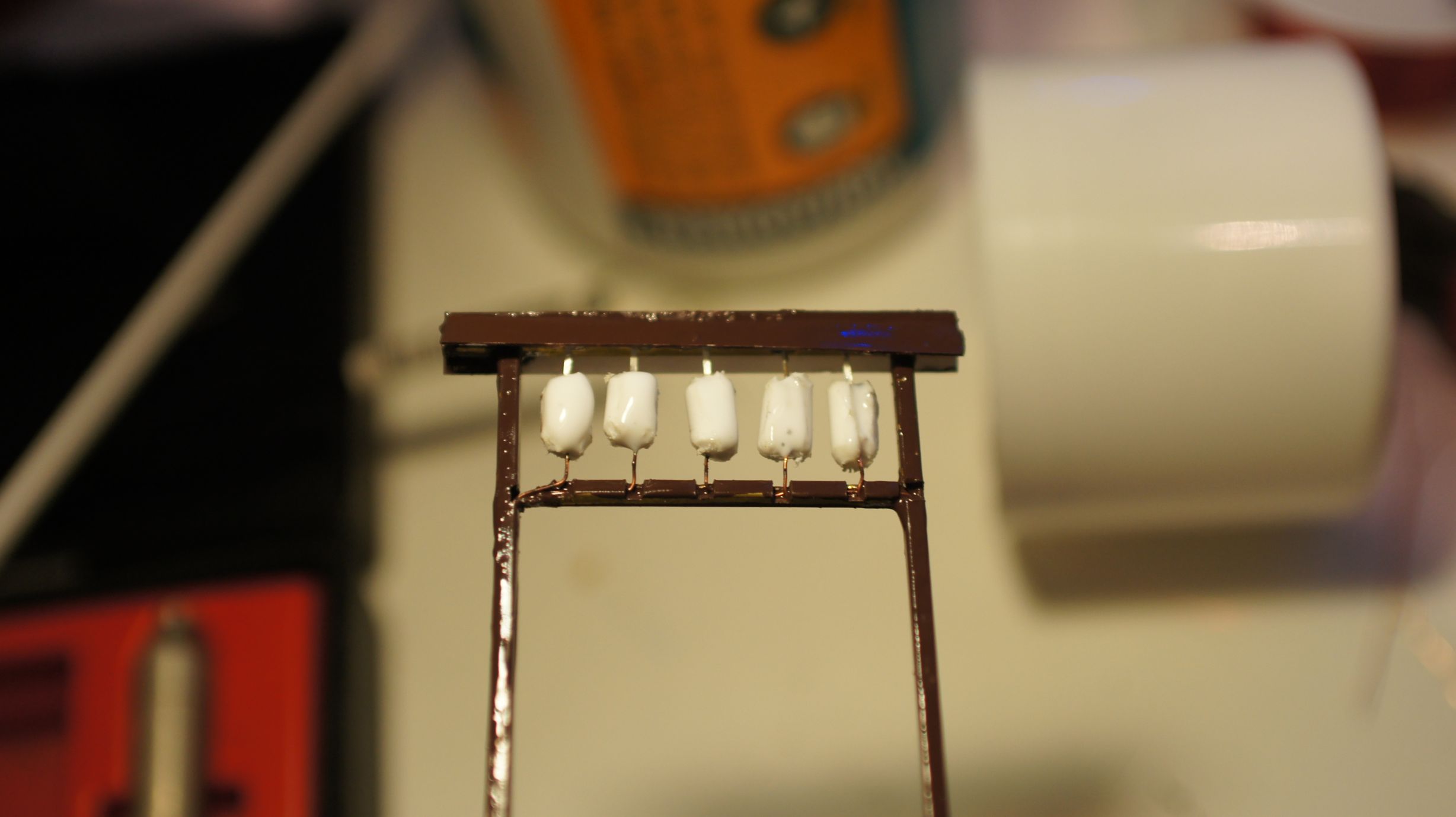
And that was it... I still think I need to place some characters on the lanterns, but I need to work out what to write on them. I also should've taken more care to get the lanterns even, but I was happy enough with the outcome and, once in place on the layout, knew it would be good enough.
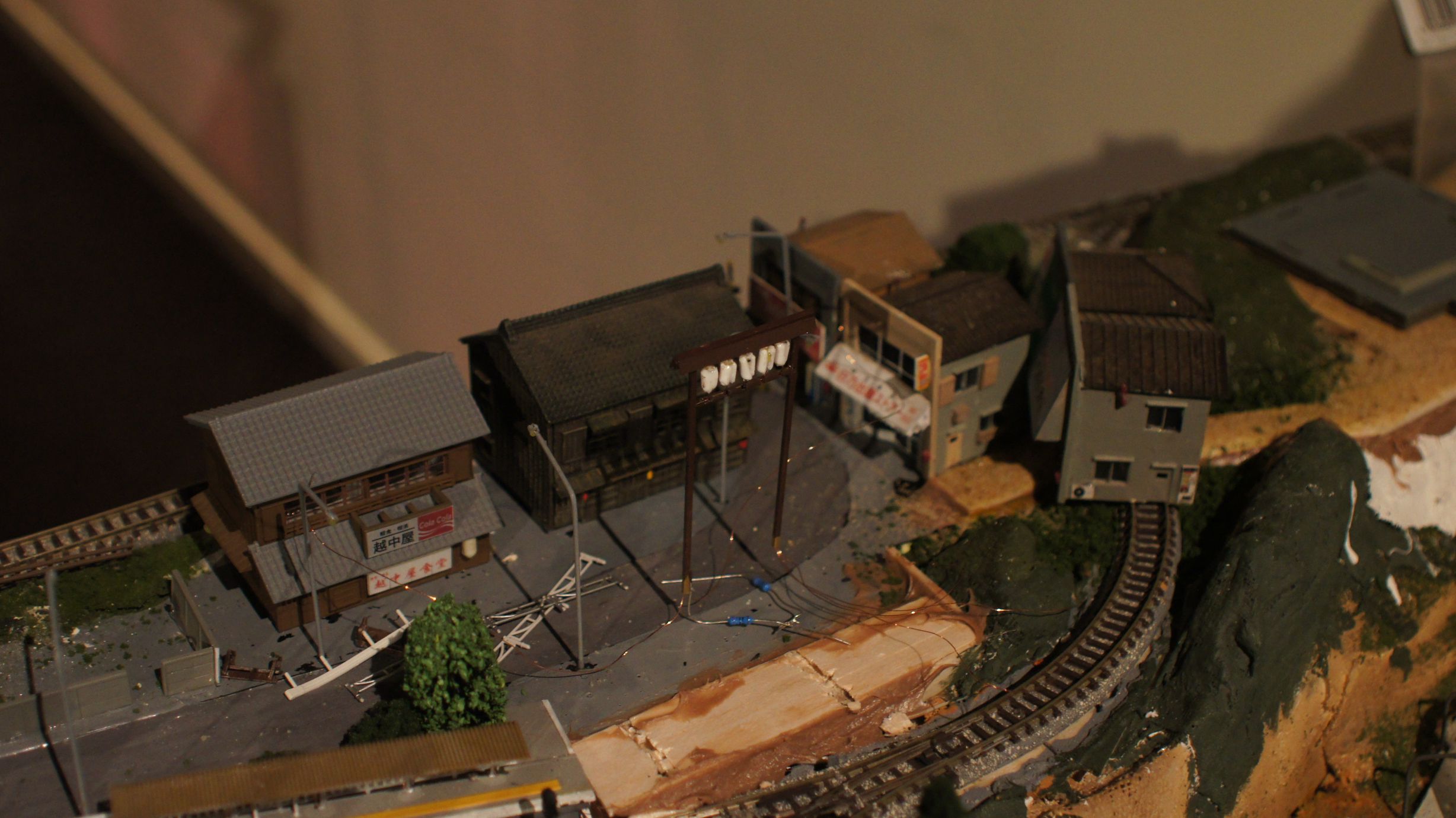
Now that the entrance is in place, it's time to get the fences and shrine in. As you can see, the foundations are there already and I'm currently working on adding lanterns and lights to the shrine.
Adding LEDs to a Japanese Shop
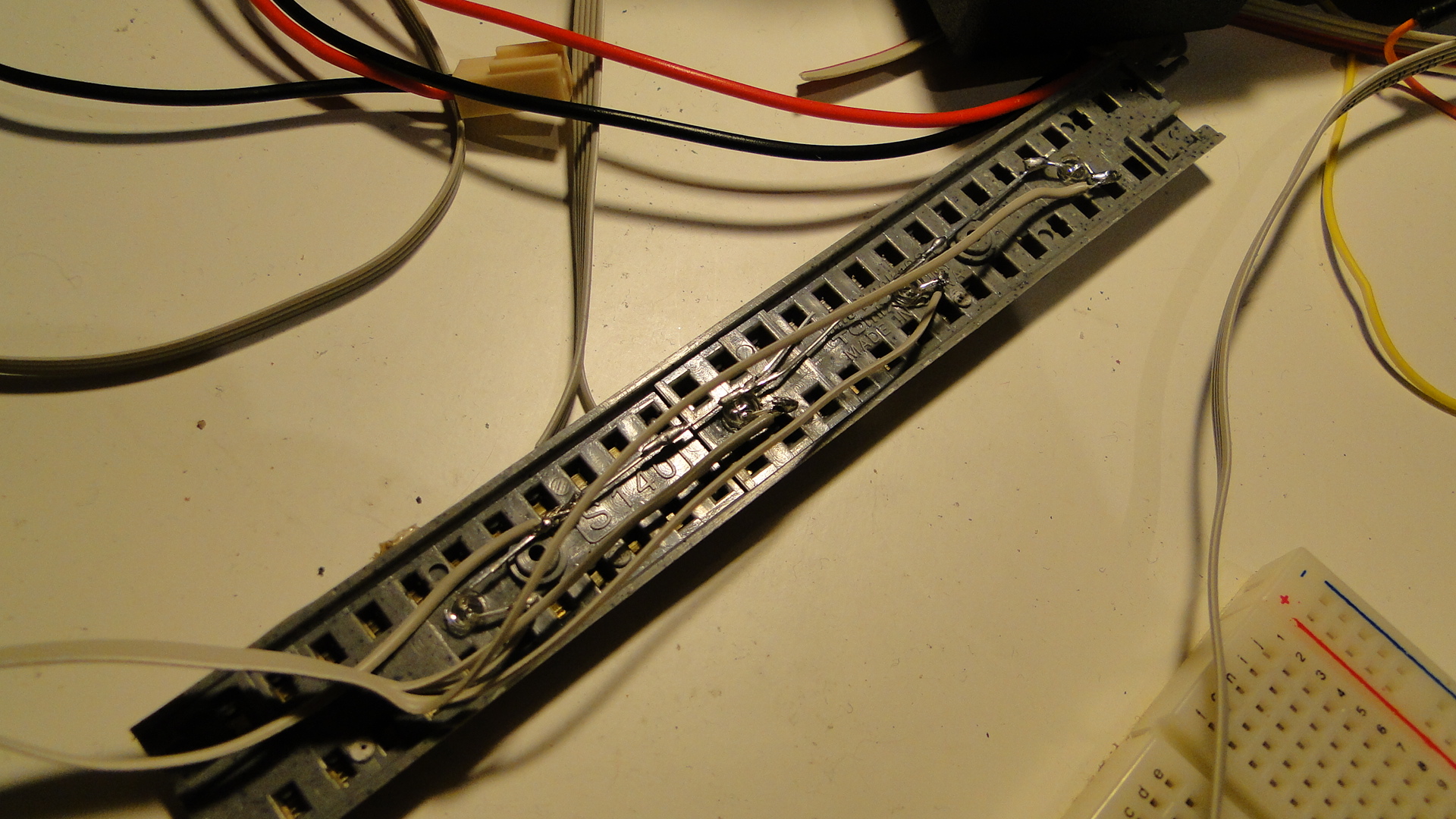
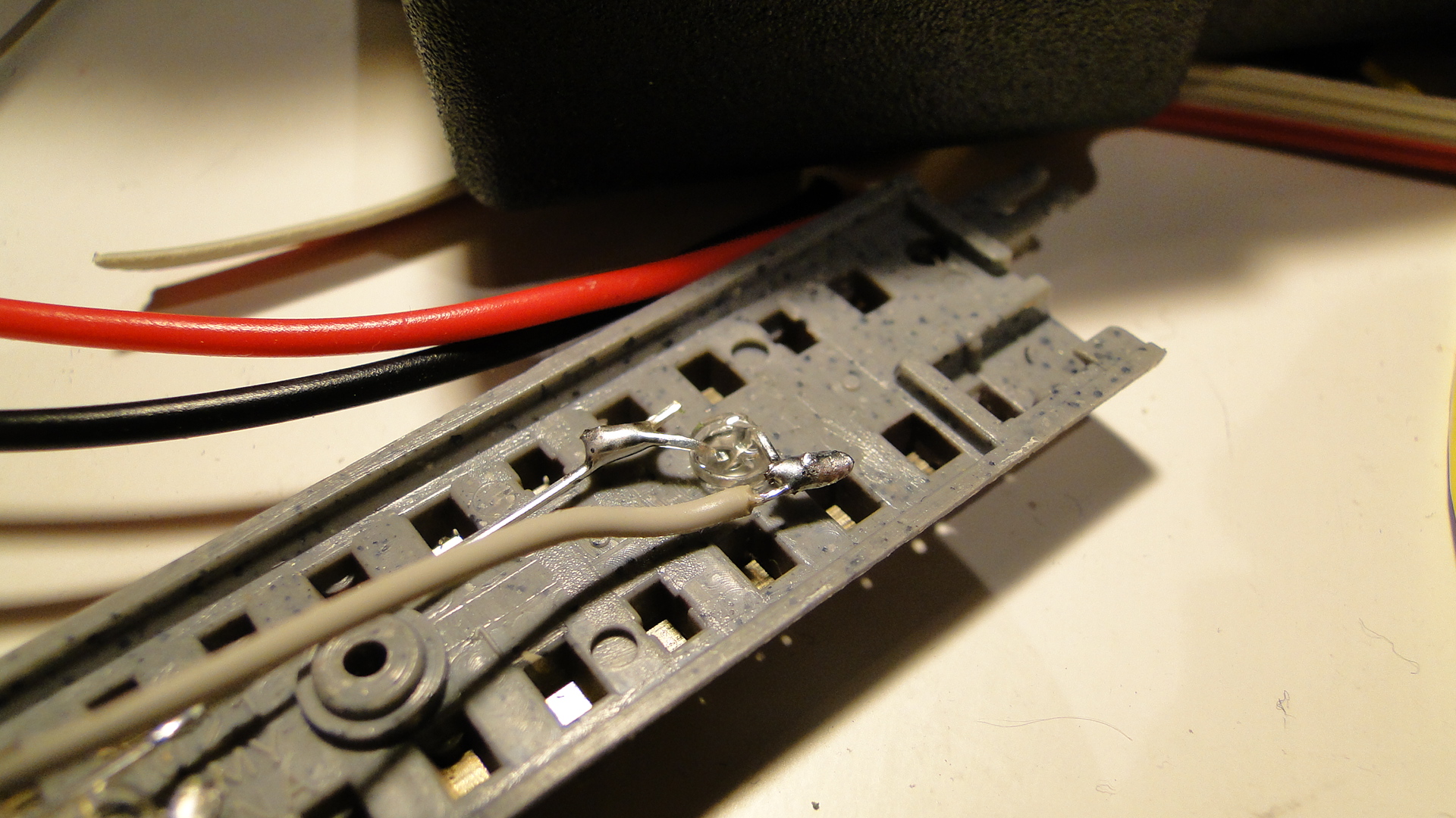
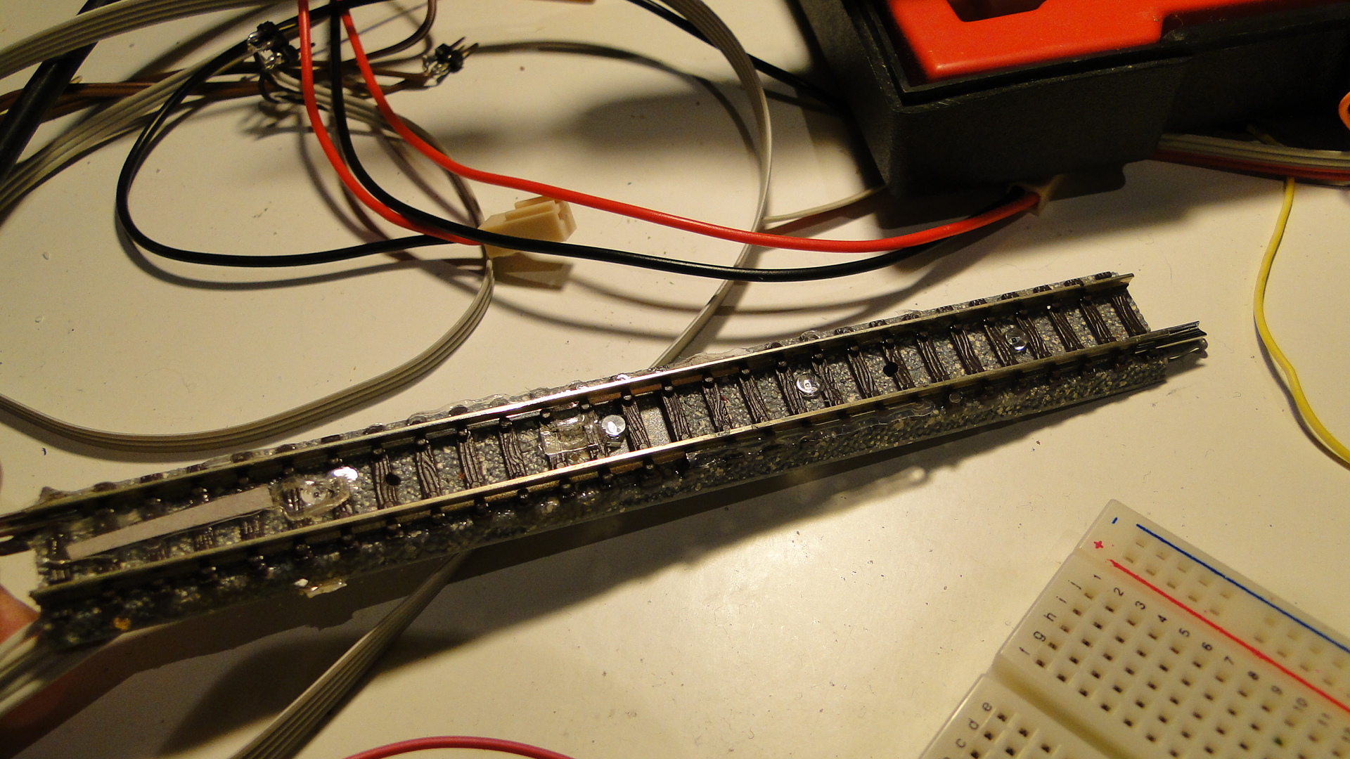
Pictures speak louder than words, so below is a quick tutorial on how to get an off-the-shelf TomyTec Japanese Shop Building lit with LED lighting. In total, this building received 6 LEDs; lantern, side-door, top floor (x2), bottom floor (x2).
Interior Lighting + Side Door


The trickiest part of this installation was the lantern that hangs out the front. I actually sliced it in half and bored out the middle to fit an LED inside. I also trimmed down the LED with a file to get it to fit a little more easily. This was done with my pocket-knife and I stopped when I felt it grinding metal. :)
Note that I borrowed ideas from this blog and I strongly recommend you check out the work the author has done on their layout!
Front Lantern


And finally, everything is wired up. You can see the huge hole I accidently drilled in the side of the shop... luckily the lantern covers it over pretty well.
Finished Product


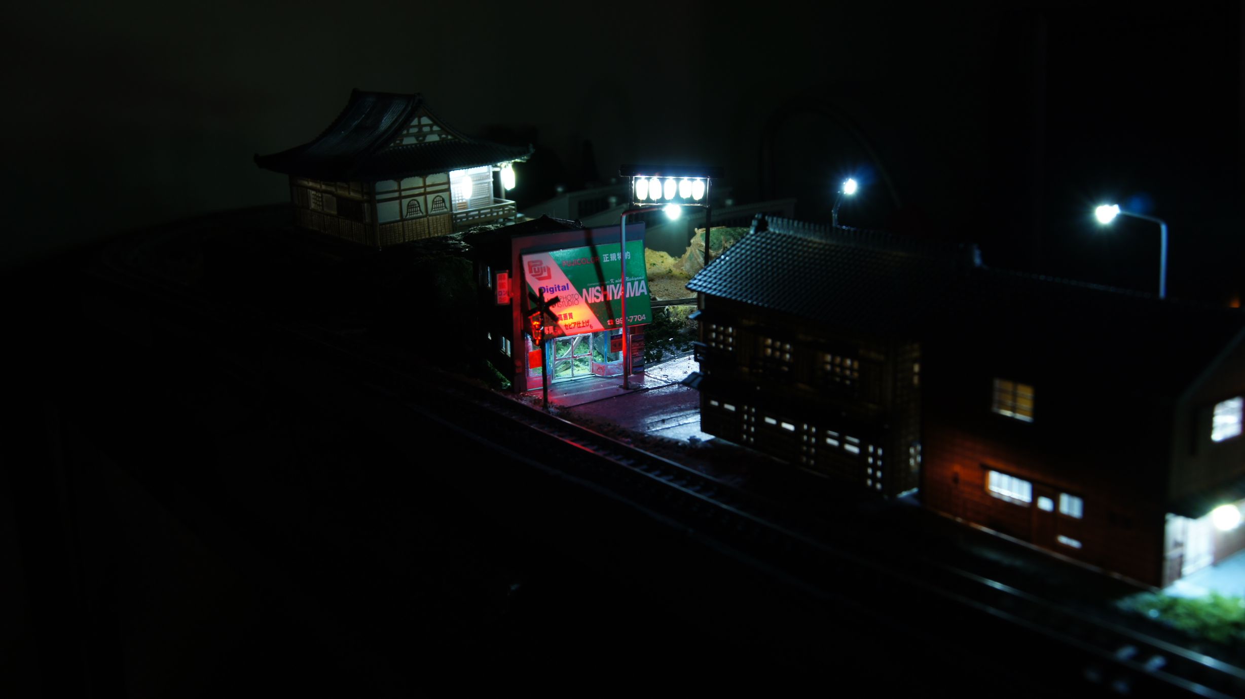
Cheap and easy Streetlights
I'd previously bulk purchased a large amount of LEDs from LED-Switch with the intent to light up my entire model railway. I'd already bought a few of the MAX7219 ICs, which control up to 64 LEDs each, and knew how to control these via the Arduino. My article on the IC and using it was here.
Anyway, streetlights were high on the agenda, as they exist in every town in Japan and, based on a very simple idea, weren't going to be too hard to make. Following are the steps involved with creating the street lights that have been visible in my prior articles.
Ingredients
- 0.25mm Copper winding wire (or as thin as possible.)
- 1.6mm LEDs White/Yellow (as available here)
- Metal tubing for the main pole. (I used '3/64 x .006' brass tubing)
- Soldering iron
- Paint


Construction
Firstly, cut the pole to your desired length. I have to admit here that I never once measured any of the poles and just prototyped one against a reference (in this case it was a standard Greenmax building) and then made them all the same size.


Make sure you take in to account where you will bend the pole and how much extra length will be required. Use a file to smoothen out the ends so that you don't damage the winding wire when fed through.


Once you have the poles made, simply cut the leads of the LED right down and solder one end to the pole itself. Finally, if you haven't already, feed the wire through the pole and tin one end (melt it with a little bit of solder to strip away the insulation.) Once done, trim away any excess tinned lead and then solder it to the other lead of the LED.


Note that the final version there was the best I'd made. I'd trimmed the LEDs right down after folding one leg over the top and used a very small amount of solder.
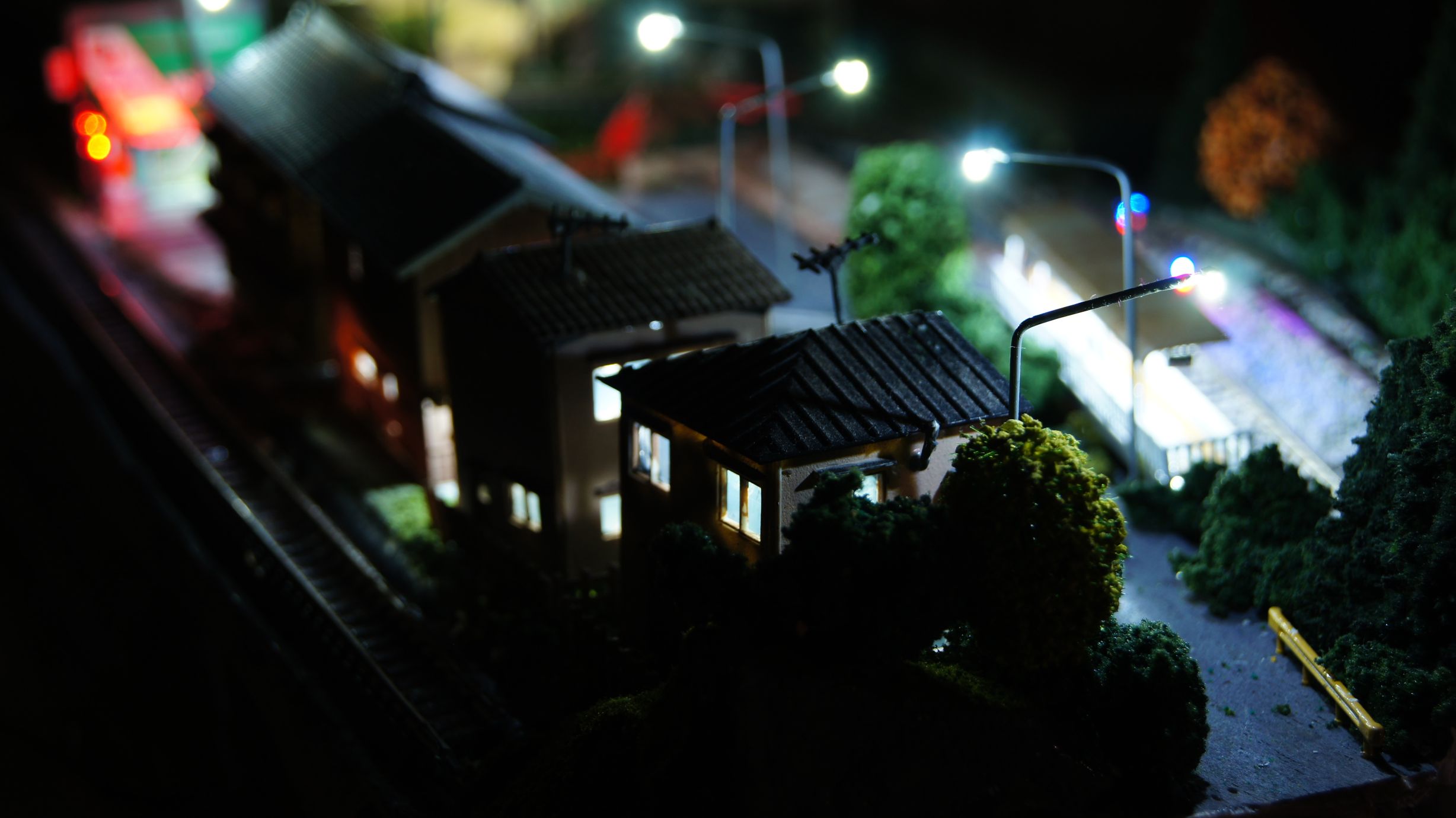
Finished Product
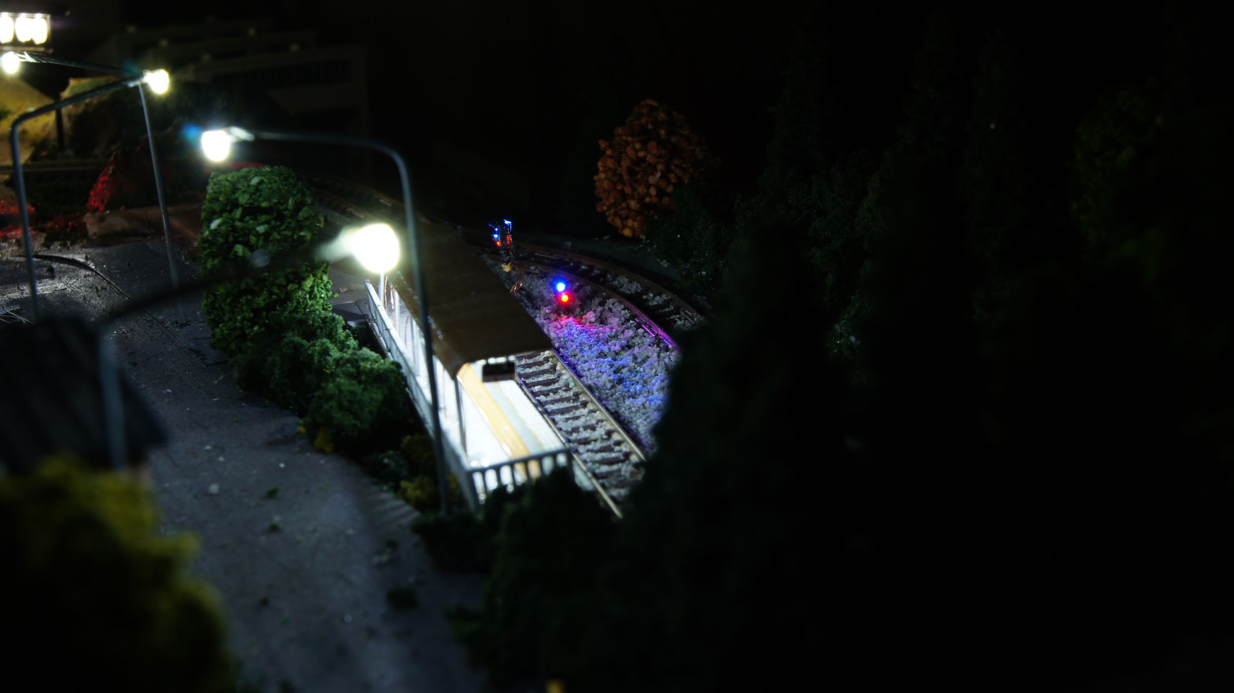
Better night shots of the taller version in action...
The only thing these really require now is some form of cover/compartment/housing for the bulb to live in. Currently, with a big enough blob of paint, I can get the ends to look round-ish enough to look acceptable and I'm happy with this. But any comments/suggestions for an off-the-shelf product that might have the right shape to cover the ends are welcome!
I'd also bought red, yellow and green LEDs and found that they had fit into the Greenmax Signals. I haven't gotten around to finishing them, but I will post another article once done.
Meanwhile, in my previous post, I also added both a red and blue LED to a Bachmann N-Scale Signal. I actually cut it off its usual pole/base and mounted them as shunting signals. See the pictures. I'll post a more detailed explanation along with the other signals once finished.
Latest on the Model Railway
So, something that was just meant to turn into a test layout has now become one of my greatest creations... It's not much as yet, but the scenery and electronics involved is a lot more complex than I thought I would ever create and I'm really glad as to how it's coming along.
Here's a gallery of the initial track plan I intended on using and then 3 evolutions of it. The final layout is not actually listed there. You can see that it started as a single level basic loop, with options for expansion. As I realised the time required for building just this module, I decided to do away with the extension options (although things can always change) and then added a second level. This was just to be a ridge down the middle of the board, but it now has transformed into 1/4 of the overall surface area. A town has now grown on top and a nice siding for single-car vehicles.
Underneath the board is a birds-nest of wiring for all the tricks I've tried with the Arduino (see all the previous posts...) and I'll show you this in a later post.
For now, just check out the photos and I'll get back with more information as I create it. I'm currently working on street lights for the top town and also automation of the points. I've been through around 5 iterations for the control circuit for the points and damaged quite a few TomyTec FineTrack Points in the process. Not fun.
Here's a link to the whole album.
Update: The streetlights are painted and in... I still need to work on the light end, they need some sort of cover/compartment.
Meanwhile, I also need to learn nighttime photography :)
More to come as I light up all of the houses; although one is already lit!
Multiplexing ‘Photodetectors’ to detect train occupancy.
Right, I wasn't impressed whilst using the Sharp distance detectors and so went back to the age-old method of light-detection between the sleepers. As this is N Scale, I didn't want the standard, large and bulky Light Dependent Resistors and went for these smaller 'Photodetectors' found on eBay from a Taiwanese reseller.
These were chosen based on the fact that they have a flat lens/front and are clear. They fit nicely between sleepers of Tomix FineTrack and, since I'd already laid and ballasted my main loop, could be retrofitted by drilling up and through the base.
Now, since I bought these in bulk, I started going crazy and sticking them everywhere I could. The goal was to put one everywhere that would become a good trigger-point for automation. I started with all of my stabling areas and put one at the start, middle and end of the sidings. I would use the 'trigger' from these to know when to slow to an engine to 50% throttle, 25% throttle and then stop. I then also put some in the tunnel entrances, station/platforms and also where signals should probably be (around points.)
It started dawning on me that I would require one analog input pin on my Arduino per photodetector. This would've gotten very expensive very quickly, but then I remembered that there was a simple tutorial on multiplexing analog inputs on the Arduino Playground (based on the 4051 IC). This IC would save me a lot of time and resources: with a little more wiring it could potentially give me 64 analog inputs for a total of 6 digital pins and one analog.
Here's the basic idea of wiring up a single 4051.
Here's how you can use multiple 4051s and reduce pin consumption:
Notes on the options in the above image:
- Option 1: Take the wires in the first rectangle and wire them to one analog pin and three digital. This will give you a total of 8 detector inputs.
- Option 2: Take the 8 analog wires and put them into analog input pins. You then also need to connect up the 3 digital pins. For all inputs you'll only ever need 3 digital pins. But for the analog pins you'll need 1 pin for each 8 inputs. (i.e. 8:1, 16:2, 24:3, 32:4, etc... there is no upper limit, as long as you have the analog inputs.)
- Option 3: Take the single analog pin and then the 6 digital pins. This will give you a total of 64 inputs and will use more digital than analog pins.
As you can see, you can interface with a lot of analog detectors, based on what pins you have available. As you may be aware, analog inputs are more 'expensive' on the Arduino than digital outputs as there are less available.
The process to control the above circuit is to set the digital pins to the desired address and then read the analog pin(s). You then need to set the next address and read the same pin (depending on your setup.) As changing through a lot of inputs and reading can take time, you need to be careful how many detectors you end up implementing. I have no exact numbers; but reading 64 inputs can easily be done in under a second. The goal is to make sure that a train does not pass a detector before it has been read!
So we have our detectors installed and circuitry built; we could now write software to manage it all. The basic idea was to read the value, adjust the min/max of that single detector and then check if it exceeded a threshold. Since these detectors required light to function, they would be effected by the amount of ambient light in the room and therefore the code would need to be smart enough to work out what was 'covered' (i.e. vehicle blocking light) and what was 'open'.
This code was also noted in my previous post where I used the Sharp detectors. These detectors produced a lot of noise and had to be filtered so that my code wouldn't simply trigger when a high/low value broke a threshold.
Here is the basic idea for reading one detector:
 read value of detector
 if (detector value is greater than recorded maximum) then record new maximum value
 if (detector value is lower than recorded minimum) then record new minimum value
 if (either min or max has changed)
  then update range of this detector [max - min]
  adjust threshold [max - (range*0.25)]
 end if
 if (detector value is greater than threshold) then
  report that this detector is 'active'
 else
  report that this detector is 'inactive'
 end if
Right, so the above concept uses a 25% threshold below the maximum-read-value to see if the value read from the detector is 'active'. It is also constantly updating it's valid reading range so that it can adapt to the environmental changes. The main issue with this concept is that if the environment drastically changes (lights are turned on/off, curtains opened/closed, etc...) then this code would not adapt, as it never has a chance to 'retract' the limits. Therefore the following adjustment needs to be made:
 store the last 32 values of detector in circular array
 read value of detector and push last into array, popping off the first value
 find the lowest value in the array and store as the minimum extremity
 find the highest value in the array and store as the maximum extremity
 if (either min or max has changed)
  then update range of this detector [max - min]
  calculate the average from the last 32 read values
  adjust threshold [average + (max-min*0.10)]
 end if
 if (detector value is greater than this threshold) then
  report that this detector is 'active'
 else
  report that this detector is 'inactive'
 end if
Here you can now see that we only care about the last 32 read values (instead of the max and min since the code was running.) We are also using a new threshold calculation: 10% above the average of the last 32 values. This therefore means that we will receive an active notification if the value increases 10% above the 'stable' value of which we have been observing.
Of course, we are always able to introduce new issues; the above code, if run at processor-speed will read 32 values in under a second and, dependent on environment changes, may well not be able to cope. We therefore need to only test the detector at a specific interval (your mileage (kilometre'age) may vary!) of say, 100ms. This then means that the 32 values are taken over the course of 3.2 seconds. If this doesn't suit, then you can also increase the buffer size or decrease the polling delay.
But I bet you haven't seen the main issue? If a vehicle is stationary on the detector for too long then the range will/should drop to zero and therefore the detector will always be 'active'.
Wait, that would be correct? Wouldn't it?
It would, but it would also then report active for a certain time span until the range had expanded again once the vehicle had moved on. Note this can also be simulated by a long train traversing the detector and blocking the light (even with intermittent gaps of light) for a long period of time.
To prevent this? Adjust the polling delay and the buffer size...
Another good trick for limiting environmental effects is to add lights/LEDs to your layout around the detectors to ensure they always have a good source of UV. That way, when those curtains close, the ranges of your detectors wont drop too low.
What's next... well, what do you want to do with all this new information? You need to read it, pass it to the methods we've described above to filter the data and then act on it. Since we're multiplexing, we need to first tell our 4051 IC(s) which input we want to read and then read it. The following classes operate the multiplexers and detectors:
class DetectorCollection {
	private:
		struct Detector {
			int dValues[32];
			int dMax;
			int dMin;
			int dRange;
			int dAverageValue;
			int dCurrentValue;
			int dThreshold;
			int dCurrentIndex;
			bool dFullArray;
			int dAnalogPin;
			int dBitIndex;
			bool dIsActive;
		} detectors[32];
		int numDetectors;
		int digPins[3];
	public:
        DetectorCollection(int _digPin1, int _digPin2, int _digPin3);
        bool AddDetector(int _aPin, int _bit);
        void UpdateDetector(int detector);
        void UpdateAllDetectors();
        bool IsActive(int detector);
        void DebugInformation(int detector);
        int GetCurrentValue(int detector);
};

DetectorCollection::DetectorCollection(int _digPin1, int _digPin2, int _digPin3) {
	numDetectors = 0;
	digPins[0] = _digPin1;
	digPins[1] = _digPin2;
	digPins[2] = _digPin3;
}

bool DetectorCollection::AddDetector(int _aPin, int _bit) {
	//initialise a detector. the array contains "zero'd" detectors
	//by default
	if (numDetectors < 32) {
		detectors[numDetectors].dAnalogPin = _aPin;
		detectors[numDetectors].dBitIndex = _bit;
		for (int idx = 0; idx < 32; idx++)
			detectors[numDetectors].dValues[idx] = 0;
		detectors[numDetectors].dMax = 0;
		detectors[numDetectors].dMin = 999;
		detectors[numDetectors].dRange = 0;
		detectors[numDetectors].dAverageValue = 0;
		detectors[numDetectors].dThreshold = 0;
		detectors[numDetectors].dCurrentIndex = 0;
		detectors[numDetectors].dFullArray = false;
		detectors[numDetectors].dIsActive = false;
		numDetectors++;
		return true;
	} else return false;
}

void DetectorCollection::UpdateDetector(int detector) {
	//set digital pins
    for (int pin = 0; pin < 3; pin++)
      digitalWrite(digPins[pin],
        ((detectors[detector].dBitIndex >> abs(pin-2)) & 0x01) == true ? HIGH : LOW);


	//read analog pin.
	detectors[detector].dCurrentValue =
        analogRead(detectors[detector].dAnalogPin);
	detectors[detector].dValues[detectors[detector].dCurrentIndex] =
        detectors[detector].dCurrentValue;


	//find the lowest and highest values in the array and store as
	//the minimum and maximum extremities.
	int tempVal, newValue = 0;
	bool extremitiesChanged = false;
	for (int idx = 0; idx < 32; idx++) {
		tempVal = detectors[detector].dValues[idx];
		if (tempVal < detectors[detector].dMin || detectors[detector].dMin == 0) {
			detectors[detector].dMin = tempVal;
			extremitiesChanged = true;
		}
		if (tempVal > detectors[detector].dMax) {
			detectors[detector].dMax = tempVal;
			extremitiesChanged = true;
		}
		//used for average calculated below.
		newValue += tempVal;
	}

		//update range of this detector [max - min]
		detectors[detector].dRange =
		    detectors[detector].dMax - detectors[detector].dMin;
		if (newValue > 0) {
			if (detectors[detector].dFullArray)
                          detectors[detector].dAverageValue = newValue / 32;
			else detectors[detector].dAverageValue =
                          newValue / (detectors[detector].dCurrentIndex + 1);
			//adjust threshold [average + (max-min*0.10)]
			detectors[detector].dThreshold =
                          detectors[detector].dAverageValue +
                          (detectors[detector].dRange * 0.35);
			//adjust active flag:
			detectors[detector].dIsActive =
                          (detectors[detector].dCurrentValue >
                           detectors[detector].dThreshold);
		}

	//finally update the next location to store the next incoming value...
	//we're using a circular buffer, so just point to the start of the
	//array instead of shifting everything along.
	detectors[detector].dCurrentIndex++;
	if (detectors[detector].dCurrentIndex >= 32) {
		detectors[detector].dCurrentIndex = 0;
		//for calculating the average, we need to know once
                //we have a full buffer. Once it's full we will always
                //have a full set of NUM_READINGS values, otherwise
		//we only have as many as dCurrentIndex
		detectors[detector].dFullArray = true;
	}
}

void DetectorCollection::UpdateAllDetectors() {
  for (int d = 0; d < numDetectors; d++) UpdateDetector(d);
}

bool DetectorCollection::IsActive(int detector) {
  return detectors[detector].dIsActive;
}

int DetectorCollection::GetCurrentValue(int detector) {
  return detectors[detector].dCurrentValue;
}

void DetectorCollection::DebugInformation(int detector) {
  Serial.print("Detector: ");
  Serial.print(detector);
  Serial.print(", APin: ");
  Serial.print(detectors[detector].dAnalogPin);
  Serial.print(", DBit: ");
  Serial.print(detectors[detector].dBitIndex);
  Serial.print(", Min: ");
  Serial.print(detectors[detector].dMin);
  Serial.print(", Max: ");
  Serial.print(detectors[detector].dMax);
  Serial.print(", Range: ");
  Serial.print(detectors[detector].dRange);
  Serial.print(", Threshold: ");
  Serial.print(detectors[detector].dThreshold);
  Serial.print(", Average: ");
  Serial.print(detectors[detector].dAverageValue);
  Serial.print(", Current: ");
  Serial.print(detectors[detector].dCurrentValue);
  Serial.print(", FullArray: ");
  Serial.print(detectors[detector].dFullArray);
  Serial.print(", CurrentIndex: ");
  Serial.println(detectors[detector].dCurrentIndex);
  /*for (int idx = 0; idx < 32; idx++) {
    Serial.print("|");
    if (idx == detectors[detector].dCurrentIndex) Serial.print("*");
    Serial.print(detectors[detector].dValues[idx]);
  }
  Serial.println("|");*/
}
And now, use it in your main program. Note I've created custom characters for the Arduino Liquid Crystal library via this website.
#define multiplexerPinBitA  40
#define multiplexerPinBitB  41
#define multiplexerPinBitC  42

#define pwmPin  			2
#define dirPin1 			3
#define dirPin2 			4

#define lcdRSPin			30
#define lcdENPin			31
#define lcdD4Pin			32
#define lcdD5Pin			33
#define lcdD6Pin			34
#define lcdD7Pin			35

#include <LiquidCrystal.h>
LiquidCrystal lcd(lcdRSPin, lcdENPin, lcdD4Pin, lcdD5Pin, lcdD6Pin, lcdD7Pin);

//cool hack! create characters for the LiquidCrystal Library!
//see here: http://icontexto.com/charactercreator/
byte trainCharFrontOn[8] =
{B11111,B10001,B10001,B11111,B10101,B11111,B01010,B11111};
byte emptyChar[8] =
{B00000,B00000,B00000,B00000,B00000,B00000,B11111,B10101};

DetectorCollection dCol = DetectorCollection(multiplexerPinBitA,
    multiplexerPinBitB, multiplexerPinBitC);

void setup() {
  Serial.begin(9600);
  pinMode(multiplexerPinBitA, OUTPUT);
  pinMode(multiplexerPinBitB, OUTPUT);
  pinMode(multiplexerPinBitC, OUTPUT);

  for (int d = 0; d < 24; d++) {
    //analogpin is 0, 1, 2 [so DIV 8].
    //(where 0 is detectors 1-8, 1 is 9-16 and 2 is 17-24)
    //bit is the 0-7 on that analog pin [so MOD 8].
    dCol.AddDetector(d/8, d%8);
  }

  //start a train: direction
  digitalWrite(dirPin2, HIGH);
  digitalWrite(dirPin1, LOW);
  //speed (out of 255 [where ~50 is stopped])
  analogWrite(pwmPin, 85);

  lcd.createChar(0, emptyChar);
  lcd.createChar(1, trainCharFrontOn);
  lcd.begin(16, 2);
}

void loop() {
  //output to the LCD (16x2) the status of all the detectors:
  lcd.clear();
  lcd.setCursor(0, 0);	//top left

  for (int d = 0; d < 16; d++) {
    dCol.UpdateDetector(d);
    lcd.write(dCol.IsActive(d) ? 1 : 0);
  }
  lcd.setCursor(8, 0);
  for (int d = 16; d < 25; d++) {
    dCol.UpdateDetector(d);
    lcd.write(dCol.IsActive(d) ? 1 : 0);
  }

  //we still have 8 characters to draw other stuff... no idea what yet though.
  delay(333);
}
And then the detectors in action. Note it was at night time and I'm surprised the result was this good!
Random Photos
Search
Tags
Links - Click for details
- Abandoned Rails (Japan)
- AIRLINE (Shinkansen Photography)
- Akihabara Station
- annexpressのブログ
- Australian Model Railway Magazine
- DCC普及協会ホームページ (Japanese DCC)
- Dead Section (Japanese Track Diagrams)
- Delicious Things (Japanese N Scale DCC)
- Densha Wotorou
- Digital Direct for Windows (DCC Server)
- Don's Dream World – AMAZING N Scale Japanese Layout
- Hatena::Diary
- Japanese N-Scale Modeling Forum
- JR Chiisai
- Kaz-T's blog レインボーライン (Rainbow Line)
- LED Resitance Calculator
- Masioka
- Poppondetta Blog
- RailFan Magazine, Japan
- Railmind
- Railway Travelers' Room
- Serenity Valley
- Shashinka Ichiban
- Shuzuku
- Sumida Crossing
- The next station is…
- Tomix N Gauge Track and Japanese N Gauge Trains
- TT Forums (Transport Tycoon Deluxe)
- 名鉄尾西線の貨物列車 (Nagoya: Meitetsu Freight)
- 日本型Nゲージ DCC改造例のご紹介 (Okiraku DCC)
- 泰 茅 轍 道 (Taichi Railway)
- 箱庭登山鉄道製作記 (Hakone-Tozan Layout Blog)
Archive
- July 2026
- May 2026
- April 2026
- March 2026
- February 2026
- January 2026
- November 2025
- October 2025
- September 2025
- August 2025
- July 2025
- June 2025
- February 2025
- January 2025
- November 2024
- September 2024
- August 2024
- July 2024
- June 2024
- May 2024
- April 2024
- March 2024
- February 2024
- December 2023
- October 2023
- September 2023
- August 2023
- July 2023
- June 2023
- May 2023
- April 2023
- March 2023
- December 2022
- November 2022
- October 2022
- April 2022
- March 2022
- February 2022
- January 2022
- December 2021
- November 2021
- September 2021
- August 2021
- July 2021
- May 2021
- March 2021
- February 2021
- January 2021
- October 2020
- September 2020
- August 2020
- July 2020
- June 2020
- May 2020
- April 2020
- March 2020
- January 2020
- December 2019
- November 2019
- October 2019
- September 2019
- August 2019
- July 2019
- June 2019
- April 2019
- March 2019
- February 2019
- January 2019
- December 2018
- November 2018
- October 2018
- September 2018
- August 2018
- July 2018
- June 2018
- May 2018
- April 2018
- March 2018
- January 2018
- December 2017
- November 2017
- October 2017
- September 2017
- August 2017
- July 2017
- June 2017
- May 2017
- March 2017
- February 2017
- January 2017
- December 2016
- November 2016
- October 2016
- September 2016
- August 2016
- July 2016
- June 2016
- May 2016
- February 2016
- November 2015
- October 2015
- September 2015
- August 2015
- July 2015
- June 2015
- May 2015
- April 2015
- March 2015
- February 2015
- January 2015
- December 2014
- November 2014
- August 2014
- July 2014
- May 2014
- April 2014
- March 2014
- December 2013
- November 2013
- October 2013
- June 2013
- August 2012
- April 2012
- March 2012
- February 2012
- November 2011
- October 2011
- September 2011
- July 2011
- June 2011
- May 2011
- April 2011
- March 2011
- February 2011
- January 2011
- December 2010
- November 2010
- October 2010
- September 2010
- August 2010
- June 2010
- May 2010
- April 2010
- March 2010
- February 2010
- January 2010
- December 2009
- November 2009
- October 2009
- August 2009
- January 2009
- December 2008
- November 2008
- October 2008
- September 2008
- July 2008