


 Melbourne BG SCS Train Timetable


Controlling your trains with an Arduino
A quick introduction to the Arduino
Arduino is an open-source electronics prototyping platform based on flexible, easy-to-use hardware and software. It's intended for artists, designers, hobbyists, and anyone interested in creating interactive objects or environments.
Arduino can sense the environment by receiving input from a variety of sensors and can affect its surroundings by controlling lights, motors, and other actuators. The microcontroller on the board is programmed using the Arduino programming language (based on Wiring) and the Arduino development environment (based on Processing). Arduino projects can be stand-alone or they can communicate with software on running on a computer (e.g. Flash, Processing, MaxMSP).
The boards can be built by hand or purchased preassembled; the software can be downloaded for free. The hardware reference designs (CAD files) are available under an open-source license, you are free to adapt them to your needs
Using it on your Model Railway
So, I recently purchased an Arduino Mega Microcontroller with the intent to control a Model Railway. This article will be the first in a series to show you how to use an Arduino to control different areas of a layout. Our first goal will be to create a controller/throttle with very basic Acceleration/Braking and a 12v DC Pulse Width Modulated output.
Note that this will all be based on DC electronics; this has nothing to do with DCC.
First, here's a list of web resources for controlling a 12v output with the Arduino:
- Basic 12v Output
- AdaFruit Motor Shield - Circuit that plugs directly onto your Arduino and provides outputs
- DIY H-Bridge Add-on
- DC Motor Control Using an H-Bridge and a PIC
- DC Motor Control Using an H-Bridge - Similar to above
- Dual Motor Driver with Arduino using a SN754410NE Quad Half H-Bridge
- L298 Hbridge meets Arduino mega
- PWM with l293/l298 - Provides great information on how to control a H-Bridge
- Controlling a DC motor with the Arduino and L293D
- DC Motor Driver v1.1
- 4A H bridge motor driver using the L298 IC
- Bi-directional Control Of Motors And The H-Bridge
- Others
What I created
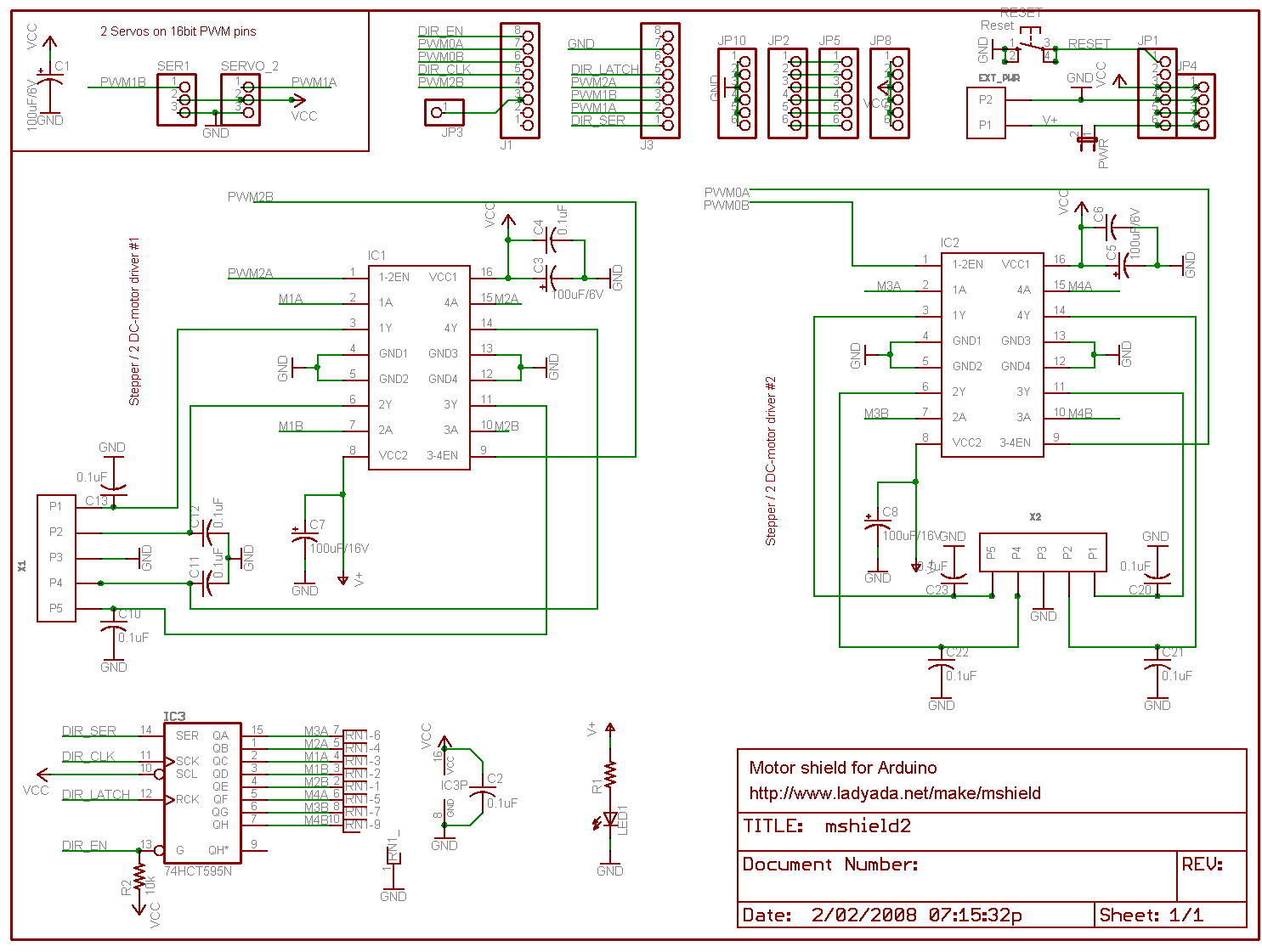
In the end I chose to use the schematics and information from the guys at pyroelectro.com which uses the L298 H-Bridge integrated circuit. My main reasoning was that, although they used a PIC microcontroller, they correctly controlled the L298 with PWM on it's input rather than it's enabling pin. Either way, the PWM signal is still created...
Here's the schematic. I've added a few extra buttons and LEDs and also added a potentiometer for speed control.
Notes:
- The IC is facing towards the viewer (i.e. so that the text on the IC is visible.)
- It's also recommended to use a heatsink!
- Ensure that you connect the ground(GND) on the L298.. It'll overheat and fry if you don't.
- You must use Ultra Fast Diodes for the flyback diodes. More information here
Right, what do you need to know?... The PWM pins are labelled on your Arduino board. By default they output a PWM signal when you feed an analogWrite(pin_number) to them. This creates a pulse that the H-Bridge will respond to. The frequency of this pulse (wave) will then govern the final output voltage to the tracks.
For direction control you either apply digitalWrite(HIGH) to PWM2 and digitalWrite(LOW) to PWM3 or vice versa for the opposite direction. Applying LOW to both pins will stop the output and HIGH to both will short circuit!
I've added S1 and S2 to control my direction. It starts off going 'forward', but pressing S2 will set the direction to backwards. The code is written to gradually stop and then accelerate in the opposite direction. Pressing S1 will then set the direction forwards again and the reverse will occur.
S3 is the emergency stop button. Resetting the throttle to zero will cancel the emergency stop flag.
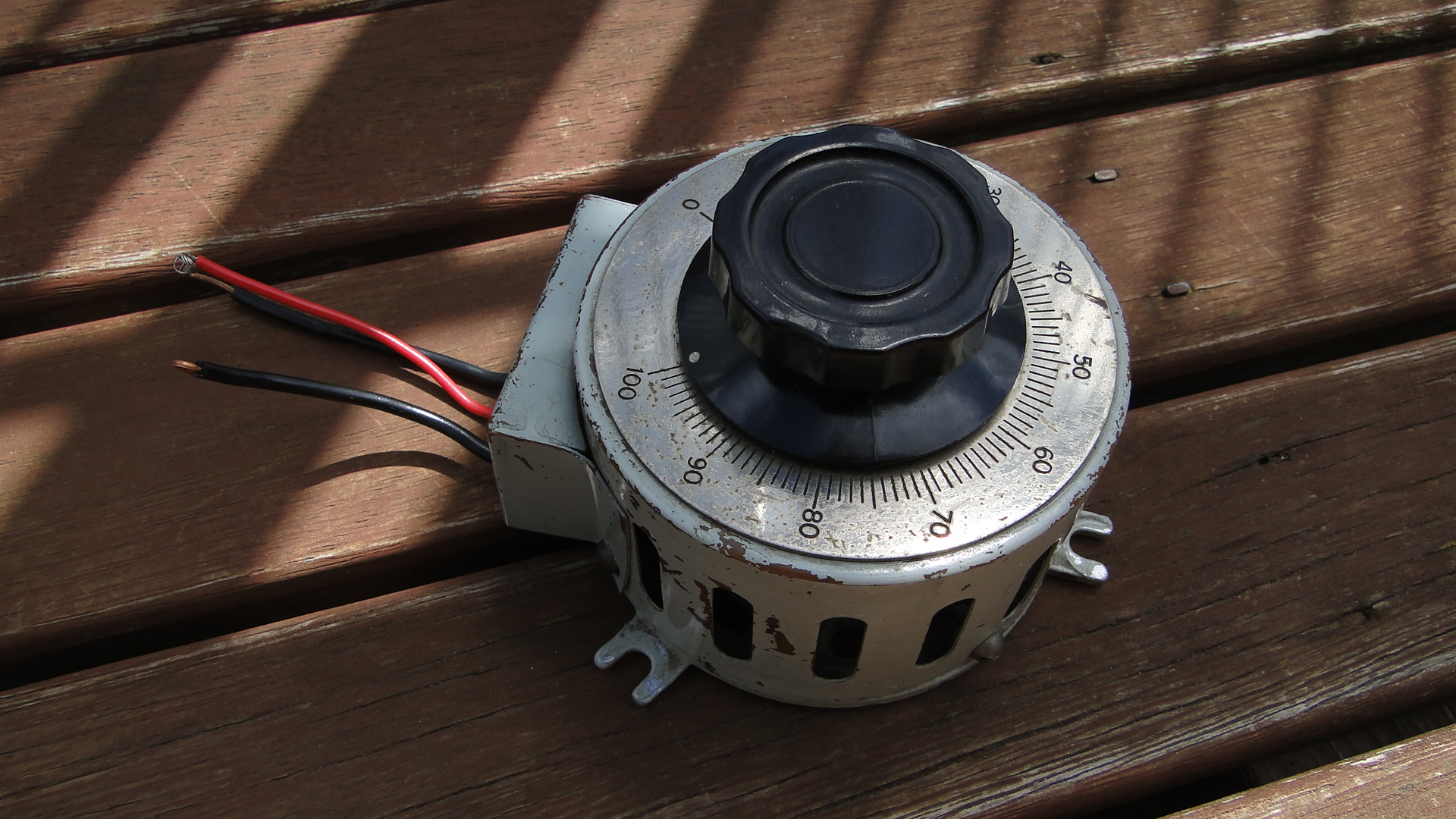
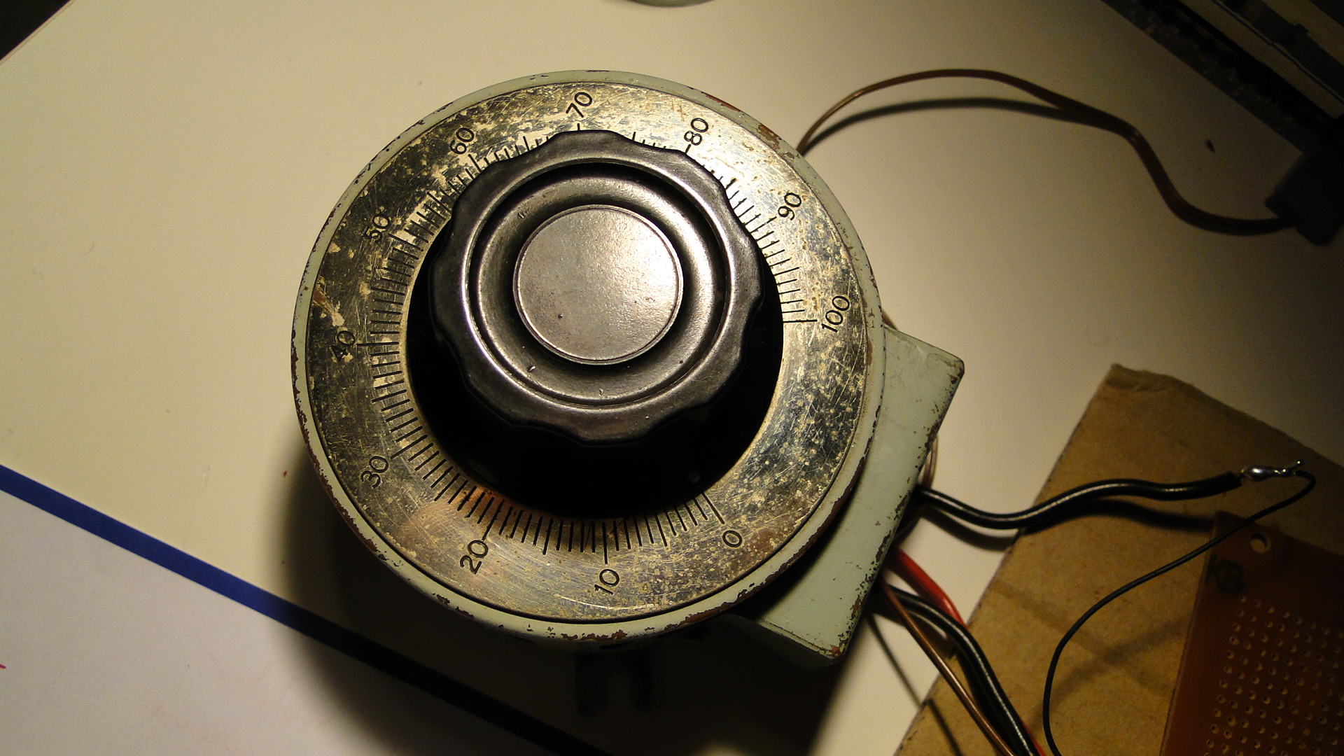
The potentiometer is the throttle... I found a huge one at an antique store down the road and love it. It's rated at 250ohm (no idea what current) and when at '100' the analogRead reports just over 1000. The throttle is only for speed, I really should add a brake lever, as when you return to zero speed the train will only gradually stop. You need to then hit the reverse (or emergency stop) button to stop the train faster.
You'll also require a 12v DC power supply. As your little engines may use up to 1A when starting, make sure this power supply is sufficient. Also, if you don't intend to have the Arduino plugged in to a computer after programming, then this 12v can also supply it (connect all ground wires together!). Just make sure it's a regulated and safe power supply. Note that different Arduinos can handle different voltages! Find your board listed here and then work out the power supply details, otherwise the Arduino Mega details are here (Input max 20v DC).
Source Code
The source code can be downloaded here.
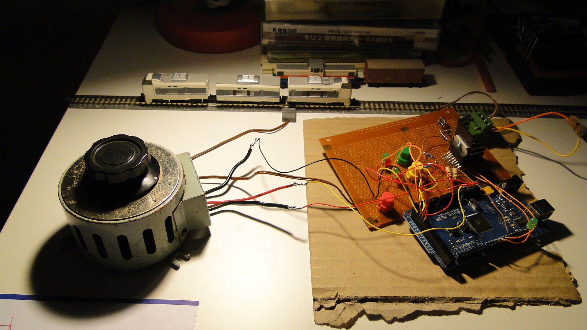
Photos
Here's a few shots of the current set up:
Please do ask any questions you have about this... I've probably skimmed over a lot and am more than happy to update this as necessary. I intend on getting on to more interesting things with this controller as I get the time.
Random Photos
Search
Tags
Links - Click for details
- Abandoned Rails (Japan)
- AIRLINE (Shinkansen Photography)
- Akihabara Station
- annexpressのブログ
- Australian Model Railway Magazine
- DCC普及協会ホームページ (Japanese DCC)
- Dead Section (Japanese Track Diagrams)
- Delicious Things (Japanese N Scale DCC)
- Densha Wotorou
- Digital Direct for Windows (DCC Server)
- Don's Dream World – AMAZING N Scale Japanese Layout
- Hatena::Diary
- Japanese N-Scale Modeling Forum
- JR Chiisai
- Kaz-T's blog レインボーライン (Rainbow Line)
- LED Resitance Calculator
- Masioka
- Poppondetta Blog
- RailFan Magazine, Japan
- Railmind
- Railway Travelers' Room
- Serenity Valley
- Shashinka Ichiban
- Shuzuku
- Sumida Crossing
- The next station is…
- Tomix N Gauge Track and Japanese N Gauge Trains
- TT Forums (Transport Tycoon Deluxe)
- 名鉄尾西線の貨物列車 (Nagoya: Meitetsu Freight)
- 日本型Nゲージ DCC改造例のご紹介 (Okiraku DCC)
- 泰 茅 轍 道 (Taichi Railway)
- 箱庭登山鉄道製作記 (Hakone-Tozan Layout Blog)
Archive
- May 2026
- April 2026
- March 2026
- February 2026
- January 2026
- November 2025
- October 2025
- September 2025
- August 2025
- July 2025
- June 2025
- February 2025
- January 2025
- November 2024
- September 2024
- August 2024
- July 2024
- June 2024
- May 2024
- April 2024
- March 2024
- February 2024
- December 2023
- October 2023
- September 2023
- August 2023
- July 2023
- June 2023
- May 2023
- April 2023
- March 2023
- December 2022
- November 2022
- October 2022
- April 2022
- March 2022
- February 2022
- January 2022
- December 2021
- November 2021
- September 2021
- August 2021
- July 2021
- May 2021
- March 2021
- February 2021
- January 2021
- October 2020
- September 2020
- August 2020
- July 2020
- June 2020
- May 2020
- April 2020
- March 2020
- January 2020
- December 2019
- November 2019
- October 2019
- September 2019
- August 2019
- July 2019
- June 2019
- April 2019
- March 2019
- February 2019
- January 2019
- December 2018
- November 2018
- October 2018
- September 2018
- August 2018
- July 2018
- June 2018
- May 2018
- April 2018
- March 2018
- January 2018
- December 2017
- November 2017
- October 2017
- September 2017
- August 2017
- July 2017
- June 2017
- May 2017
- March 2017
- February 2017
- January 2017
- December 2016
- November 2016
- October 2016
- September 2016
- August 2016
- July 2016
- June 2016
- May 2016
- February 2016
- November 2015
- October 2015
- September 2015
- August 2015
- July 2015
- June 2015
- May 2015
- April 2015
- March 2015
- February 2015
- January 2015
- December 2014
- November 2014
- August 2014
- July 2014
- May 2014
- April 2014
- March 2014
- December 2013
- November 2013
- October 2013
- June 2013
- August 2012
- April 2012
- March 2012
- February 2012
- November 2011
- October 2011
- September 2011
- July 2011
- June 2011
- May 2011
- April 2011
- March 2011
- February 2011
- January 2011
- December 2010
- November 2010
- October 2010
- September 2010
- August 2010
- June 2010
- May 2010
- April 2010
- March 2010
- February 2010
- January 2010
- December 2009
- November 2009
- October 2009
- August 2009
- January 2009
- December 2008
- November 2008
- October 2008
- September 2008
- July 2008
February 8th, 2010 - 21:43
Very nice! I’ve been thinking about doing this lately myself. I wonder where we could have custom levers made up…
February 9th, 2010 - 09:20
I’d say a trip to the local hardware store would get you enough random bits and pieces to build something. Otherwise you could get your hands on a Densha De Go controller; of which I have for the Dreamcast, but am having troubles attempting to decode. That will be the next topic, if I can successfully communicate on the maple protocol :)
June 4th, 2010 - 23:23
Quick question: Does the L298 output a smooth DC signal, or a PWM signal? I’m thinking now of building one following your model, but I do not want PWM output to my tracks (because I’m going to also use it as a “jump throttle” with my Digitrax Zephyr, which requires smooth DC output).
June 7th, 2010 - 12:54
As far as I am aware the output signal is totally dependent on the input signal. If you pulse the enable or directional pins (as is done to create a ‘pwm’ signal in most examples) then it will output PWM.
Otherwise, a constant voltage applied to the correct pins will see a constant output voltage; Therefore creating clean DC power (afaik.)
December 31st, 2010 - 12:32
This is very interesting info. I’m considering using this method to control micro slot cars. If you have made any further improvements since your last post, please let us know. Once again thanks for posting this.
Martin http://www.HeliumFrog.com
January 4th, 2011 - 11:45
Martin, thanks for your interest! I am still using the exact same circuitry to control my Model Trains. Controlling slot cars wouldn’t require any changes to the project, but you’d have to be careful as to the final voltages on the tracks? I imagine they don’t use a full 12v?
Either way, you’ll lose about 20% on the output, so make sure your input is provided accordingly.
November 7th, 2011 - 14:14
Steven,
Great concept. I have need for a DC controller that will work with JMRI so that I could use the EngineDriver app on my Droid phone. If I was able to use JMRI I could use my Droid phone as a throttle and have engine sounds/Horn/Bell play through my laptop speakers. Will your design work with JMRI????
November 7th, 2011 - 15:37
Ok, there’s probably a few ways to do this… but the most straight-forward could be to create an SRCP server either on the Arduino code itself, or as an application on the host computer that then communicates to the Arduino over USB/Serial.
SRCP is the protocol used for DCC, so it may be overkill for JMRI and DC on this, but it should work. I had a quick look at the ‘hardware’ for JMRI but couldn’t see an interface for standard DC controllers.
If you had an Arduino with the Ethernet sheild and wrote the SRCP server into the Arduino then you wouldn’t need a computer at all.
January 20th, 2012 - 03:05
Read your article withgreat interest. Love the application. Need an HO controller here, desparately.
You did not identify the Arduino board nor provide a parts list, (circuit board, leds, pinout, code entry, etc).
Can you help?
Sincerely,
Lansing
January 20th, 2012 - 19:29
Frank, as stated in the first main paragraph, the Arduino I’d chosen and used was the ‘Mega’.
As the circuit diagram shows, the parts list is as follows:
– L298 Dual Full-Bridge Driver
– 0.5 Ohm 5W Resistor
– Potentiometer (This is the throttle and it’s ohm rating doesn’t exactly matter as you can fine-tune it with the Arduino’s analog input reading commands. Either way, 10k is a good number.)
– 4x UF4003 diodes as ‘fly-back’ to prevent motor current from trashing the circuitry.
Although simple, the circuit diagram does show everything you’ll need to power the throttle and therefore your trains! :)
You could also ammend the diagram to add in an LM7805 from the 12v power to power the ‘logic’ side of the L298, but that’s not too much of a priority. If you do power it externally make sure you connect all the GNDs together.
Steven.
May 28th, 2012 - 12:49
Hi,
I was confused with your code as I don’t really now what the pin 50,51,48,49, etc was assigned to. Could you comment on that?
May 28th, 2012 - 13:09
Sue,
Each of those 4 pins are LEDs, and I must apologise that they don’t actually match the diagram above in the post.
The code is very rough, but will do what you want… you’re more than welcome to remove everything regarding the pins you have mentioned.
The LEDs on 47 and 48 will illuminate/flicker if the throttle does not match the speed (i.e. accel or decel) 47 when moving in dir ‘1’ and 48 when dir ‘0’.
Those on 49/50 are the ‘stable’ speed LEDs. 49 will light when the dir is ‘0’ and the speed is stable (throttle == speed) and likewise 50 will light when the dir is ‘1’.
51 and 52 inputs matched to the direction buttons and will change the direction accordingly.
Steven.
February 8th, 2013 - 23:05
Hey how i change the code to arduino uno?
February 16th, 2013 - 08:24
Trevor,
You’ll just need to use the pins available on the UNO and change the values in the code.
Find the PWM pin (should be labelled on the board) and use it where appropriate.
Steven.
March 6th, 2014 - 22:19
Hi I’m Gabriel.I am 12 years old from Malaysia.I am very keen on this project which you have authored.Could you please tell me where to get the parts,and also could you please email me,the parts list please?
Thank You!
Your sincerely,
Gabriel Ng.
March 7th, 2014 - 13:42
Hello Gabriel,
You’re best bet nowadays is to just buy a “Motor Sheild” for your Arduino.
Which model Arduino do you have and what have you coded/tested so far?
Check on eBay for a shield… a lot of them use the L298 already!
Steven.
April 3rd, 2014 - 01:18
Great stuff! Really helpful.
Sorry for a daft Q: Is this type of L298 from ebay the right sort of thing? Looks very different….
http://www.ebay.co.uk/itm/Dual-H-Bridge-DC-Stepper-Motor-Drive-Controller-Board-Module-Arduino-L298N-AR-/301004319326?pt=UK_BOI_Industrial_Automation_Control_ET&hash=item4615416a5e
Also, I can’t see in your code anywhere the “emergency stop” button. Am I missing this bit… is it hidden in “dir” somewhere?
Thanks!
April 3rd, 2014 - 09:11
Roger,
That board will work fine. It has the same chip and easy connections.
As for the emergency stop button… It seems I never coded it. You’ll want to add a button to a spare pin and then just set the throttle to zero when a change is detected.
Steven.
April 4th, 2014 - 02:43
Thanks for clearing that up!
I know it’s annoying when ppl ask easily googleable questions, but honestly I have searched far and wide and read the datasheets etc; could you help me with a couple of key things?
1) Am I correct in thinking that your setup as described, provides constant SPEED output, ie if the train goes uphill the motor voltage (current?) is increased to compensate and thus maintain the same SPEED? Is this done completely via the current sensing B input and 0.27 ohm resistor?
2) If the above is true, can I have a switch to control either constant SPEED (as above), or instead the more traditional constant voltage (current?), that would require the operators skill to adjust the control knob as the train hits hills etc? Would this be a case of adding a SPST switch between the 0.27 ohm resistor and the GND, so make the connection for constant speed, and simply break the connection for constant Vout?
I’m planning to build one of these type controllers end of April.
April 4th, 2014 - 09:09
Roger,
Too much benefit given here… the 0.27ohm resistor simply keeps the L298 running when there is load. It doesn’t provide any sensing.
This is actually a really cool idea though… if you hooked up a line from between the resistor and the L298 to an analog input pin then you could watch the current draw and amend the throttle accordingly, thus simulating speed decreases when the model has to really pull.
Of course, you’d really have to load up your cars/wagons… N-Scale really doesn’t do justice to scale of gravity and inertia.
Steven.
April 5th, 2014 - 19:38
Ok, my brain is really hurting here. Put simply, what does the “Current sensing B” pin do, and how does it actually work? I have read a lot but am still somewhat puzzled.
If I want a constant speed up a hill, then would it work as you say; ie, is the “current sensing B” effectively an output from the L298 that I could feed into an analogue input to sense an undemanded decrease in speed (starting to climb the hill), and consequently increase the PWM output number to compensate?
Or would it be a completely seperate unit? Using 12v rail power, 1A max, only want to input 4v/40mA max into the arduino, so R=V/I, use 220 Ohm 1W resistor. Use 2 resistors in series to connect the rails together, and pass the voltage between the 2 of them into an analogue input. Does that make any sense?
Rail Rail ↓ ↓ Resistor--Resistor ↓ Analogue pinApril 6th, 2014 - 14:42
Roger,
The L298 is a “Dual H-Bridge” meaning that it has two channels to amply current contained in it. See the diagram on page 1 here: https://www.sparkfun.com/datasheets/Robotics/L298_H_Bridge.pdf
Therefore, all pins on it (apart from the common/power/gnd pins) are duplicated. For a channel to function, you need an input voltage on both ‘In’ pins and the ‘Enable’ pin for that channel brought high. You also then need an appropriate resistor to ‘pull down’ the sense pin. This then controls how much current the output is allowed to draw. You could actually put a chunky potentiometer on there to variably control the max output.
If the resistor is not low enough, then the L298 will kill the output when too much current is drawn. I was experiencing this when playing with DCC on N-Scale as having 2 trains (or just locos) starting at once threw the circuit.
From this, you therefore need to choose a team, be that channel A or B and then work with those pins only. You, of course, can bridge both channels (means that you get double the amperage to play with) and then watch both current sense pins. The value you read on each should be the same in this case. Don’t join the pins together before the resistor though! Have two analog pins watching, one for each.
Now, for power, 4v may well not be enough for the Arduino. I’d recommend you power it with the same power used for the track. The Arduino has an on-board rectifier (usually a 7805) to bring the input down to 5v. You can feed 12v directly in to it. They recommend any power supply with an amperage over 250mA.
Share a common ground too: link ALL GND pins (Arduino, track, L298) together to ensure that the timing of the circuit is correct. Otherwise you wont have a baseline for analog pin sensing.
Finally, as for the formulation of the value to work with on the current sense pin(s)…. I’ve no idea. The maths escapes me right now. I recommend you hook all this up. Draw a circuit diagram and take a photo and email it to me if you want clarification. Once you have the analog pins reading the current sense, then test a train and see what values you are getting. Have your code record the max and min and the datetime to the serial console you can tell when the spikes are. Drive a train up an incline and see if anything changes.
I’d love to see the results!
April 23rd, 2014 - 16:45
I’ve not forgotten you! I’ve drawn up circuits for the current sensing, and also back emf measurement. If you’re interested in following how it goes, drop me an email at the address given.
Otherwise, thanks for the help with kicking me off!
April 16th, 2014 - 09:33
G’day StevenH,
I have been following with much interest how you have done all of
this and have started to automate , my old dc n scale.
In regard to the l298, is this an equivalent unit
http://australia.rs-online.com/web/p/motor-driver-ics/7147711/
Or this one
http://www.digikey.com.au/product-detail/en/A4954ELPTR-T/620-1384-6-ND/2509922
The voltages concern me,
Cheers steveG
April 17th, 2014 - 11:14
SteveG,
That driver will work fine… both the L298 and A4954 are rated somewhere up to 40v. In the end it’s the amperage that counts anyway… you can combine the bridges in both to double the output.
It seems you can even buy the IC you’ve mentioned as a kit from Jaycar.
http://www.jaycar.com.au/productView.asp?ID=XC4264
http://www.freetronics.com/products/hbridge-dual-channel-h-bridge-motor-driver-shield
Steven.
April 19th, 2014 - 06:19
G’day StevenH,
Yes I saw those shields, and I have the one direct from freetronics and it works well.
I have 3 layouts as moduels that I want to control, 16 on one layout and 7 on the others so even using the dual channels, it would become expensive.
I am hoping to mimic what you have created using the IC instead of the shields, reduced the cost substantially.
:)
Cheers, SteveG.
December 14th, 2016 - 01:50
Hi
I have just started using z gauge and am very interested in the use of Arduino with the control of my setup. As a complete novice in electronics I welcome your opinion on whether you think your system is suitable for z gauge. I do know that Marklin z gauge only use 8 volts.
Many thanks Dave k
December 16th, 2016 - 08:09
Dave,
This circuit will work fine. The output voltage is limited by the input voltage, so if you use your existing transformer and supply 8volts on to the L298 (or other such motor controller for the Arduino) then you’ll be fine!
Steven.
February 14th, 2018 - 23:38
Steve,
I am not understanding the pins used in Arduino. Could you clarify this point?
tks.
February 28th, 2018 - 11:45
Sure, which Arduino are you using?
March 6th, 2018 - 09:01
Arduino UNO.
tks
February 8th, 2019 - 06:05
Is there a way to make a Loco Decoder, out of an AtMega chip, for loco control?
February 8th, 2019 - 08:01
AtMega may be a little large? But I’ve just had a quick search and you’ll find many examples for creating an actual decoder: https://www.google.com/search?q=atmega+dcc+decoder
July 13th, 2019 - 20:53
Hi, I am using an L298 shield with a UNO to control 12v DC layout. Reason being, i want the Arduino to know speed & diirection of locos (coupled with IRDOT sensors for location) to make other stuff happen on the layout.
Big problem is the motor noise…. it whines loudly regardless of speed setting and i notice both LEDs on the L298 output are lit? If I replace the loco with a 5w lamp, only 1 led lights at a time depending on direction selected. Anyone got any ideas? Thanks.
July 15th, 2019 - 09:06
Paul,
It sounds like your PWM cycle frequency could be too low?
Can you share the code/sketch? Or just the parts where you set up the shield?
Steven.
August 2nd, 2019 - 01:00
Hi,this project just for me,pls.can you show me which pin to Mega
Because I dont found PWM1,PWM2,PWM3
whic number will be on arduino
I saw on picture some it is like 51,50,
can you showme pls
best Regards
Kadirisan
August 2nd, 2019 - 11:33
Kadirisan,
This really depends which Mega you have!
The latest Mega at Arduino is here: https://store.arduino.cc/usa/mega-2560-r3
The documentation suggests:
PWM Pins: 2 to 13 and 44, 45, 46.
Hope this helps.
May 21st, 2020 - 10:28
Check this out. https://www.arduinorailwaycontrol.com/