


 Melbourne BG SCS Train Timetable


Macintosh System 7 on x86?
Rabbit holes... My regular morning peruse of HackerNews saw me read this article on Mac OS X being ported to the original WII. Amazing, I thought to myself... I wonder if I can skip the emulator on my X68000 and port Macintosh System 7 to it directly?
I went off to read the actual blog over here. Brilliant write-up and beautifully presented. Coding on Trains and Planes... and even in Hawaii? Love it!
The comments on HN had interesting hints to the source of System 7 being available? I googled and found this github project. WTAF? Hah. Someone is having a good set of 'sessions' with an AI agent, making it disassemble, understand and re-write System 7 so that it'll work on x86? There are even released ISOs? Nuts! Does it work?
& 'C:\Program Files\qemu\qemu-system-i386' -cdrom system71-en.iso -vga std -m 256M
And wow.. it... works?
A bit clunky. Mouse works and Simpletext opened! What about on real hardware?
Burn a disc and then see if my Dell Dual-PII will boot it...
5 seconds later and we were in! Mouse moved for a bit then it all locked up. I'M IMPRESSED! Keep this alive!
Sharp X68000 Pro – RAM + HDD + Power
I couldn't believe it. seeing a full set X68000 Pro on the shelf at the Ota Road Super Potato in Den Den Town, Osaka. Of course, the staff instantly told me it was for display only and didn't work! The story was that they'd bought it a few years back and it worked then, but since had stopped working. The monitor was fine, but the main CPU was not turning on. It was therefore 'KAZARI'... decoration.
I was happy with decoration, for the price. Shipping was to be another concern. Fortunately, Super Potato is partnered with a logistics firm upstairs and Mori-San and X-San helped describe the process to me. I'd buy the unit on the day and wait until after Golden Week for them to contact couriers and provide a quote. I'd then pay via Paypal and they'd ship the unit to me! Easy!
To be honest, after turning on and playing a few rounds of Bubble Bobble, the poor thing has been sitting as KAZARI in the corner of my study/office for quite a while. I recently made a 3D-printed bezel cover for the monitor, which doesn't look too bad! Regardless of all the work to that point, I'd recently come to the realisation that I either need to move it on... or actually learn how to use it!
The machine works great... floppy games load fine... but that's not fun-n-technical enough... I want to use HDDs, CDs?, MOs? and work out what that CPU Clock Switch does... and how to use the memory cards. Also, can I rig up an ethernet to serial adapter to get data transferring over to it a little more easier? Maybe even use a BBS?
Random Access Intricacies
Understanding RAM in an X68000 is mildly difficult. It seems that, nearly akin to an Amiga, there's a clear distinction between system/onboard RAM and extra supplementary RAM. I suppose that goes for PCs too with conventional vs. extended RAM, etc... Anyway, to use any I/O slot memory expansion boards, the base system needs to have 2mb of internal memory. From the factory, X68000 ACE, PRO and PROII systems only have 1mb and so a CZ-6BE1A module is required. Fortunately, this machine already came with the module installed!
With 2mb onboard, you can then tinker with I/O slot memory cards. I was googlin' at some point and saw a good deal on an XSIMM10 card, so I bought it! Little did I think to check the blank plates on my machine to see if I already had one? Turns out I did! How hilarous.
Left-most above is an I.O Data PIO-6834-4 4mb memory expansion. There's a jumper block to set where this memory starts in the memory map. Since we've got 2mb onboard, this card must start straight after that and provide another 4mb, taking the machine to 6mb.
The other board above is a XSIMM10 memory board which will allow up to 10mb of memory to be added! These cards can be configured to place the two pairs of memory wherever needed. Interestingly, the configuration examples show a 4mb "system" area above the 10mb additional RAM? Does that mean these cards can be used together?
In the end I only used the XSIMM10 with the full 8mb populated to bring the machine to 10mb.
SASI/SCSI HDDs
There's a great tutorial here for setting up HDDs. It seems tho, that you're expected to use one of the devices specified and not just boring old spinning-rust. I tried three external SCSI drives that I had laying around, connected to the 50-pin SASI centronics port and couldn't get any of them to work. Anything from stalling INITs to "device not operational" to "cannot xxxx".
After trying the units above, I turned to the internet and sought help. This magical post indicates that not many SCSI drives are compatible and for those that are, they need to be able to have parity disabled. I don't even know what that is! That flat beige unit above has an ST11200N inside... and it seems that parity should be disabled by default. I popped it open and found...
A slew of jumpers enabling parity! I disabled it, but had no luck.
Further goog'lin brought up this excellent article at gamesx... and that last little paragraph is a killer.
SASI models will be somewhat limited in terms of what drives can be used. First and foremost you'll need a drive that doesn't require parity (if you don't want to build the parity faker circuit). Even then, you'll run into plenty of drives that just won't work even though they can have their parity disabled.
There's a table there with two 1GB drives listed... and they're both listed as no-worky. The table also lists the Quantum ProDrive LPS42S as 'working', and I have two in my HDD box'o'junk!, so I tried them all out. After a lot of tinkering, I couldn't get any of those to work either. So, I tried my SCSI2SD. It also showed no signs of life, until I jumpered the Termination Power pins!
The best thing is that I have a terminator with an LED in it, no idea where that came from, which shows me if the bus has power on it. The LED only illuminates when there is termination power on the bus and, up until this point, it'd been off the whole time. Finally, with the SCSI2SD TERMPWR jumpered, the light lit up!
Of course, if I'd read the bloody manual for the SCSI2SD earlier, it would've been obvious from day one:
    Sharp X68000
        SASI models supported. See gamesx.com for information on building a custom cable.
        needs J3 TERMPWR jumper
        Set to SCSI ID 3. ID0 will not work.
Ok, we're learning. From here, with the drive initially as ID 0, the machine would freeze if the drive was already powered on before the machine was started. So, instead, I started it after the boot process.. allowing me to format it! I then set the drive back to ID3 and, after following these instructions, I installed the SxSI BIOS in SRAM and the machine booted from the drive!
So, with this now understood, could I get an older drive to work? The Conner 3040 42mb Drive supposedly has Termination Power and Parity options. With this drive connected... the terminator light... didn't light up?
So, can we inject terminator power? In the SCSI2SD schematic, they're just feeding +5v into pin 26 on the SCSI cable, but then also providing 3v3 to the termination resistors... does my "active" terminator with the LED also do the 3v3 conversion and just needs the 5v power rail?
Actually, we can test this using a better method first. Let's leave this unit on the SCSI chain, but set it up to some higher ID and then slap the Conner at ID3 before it. Even with all this trickery, I couldn't get a spinning-rust drive to cleanly format.
So, instead, let's switch back to the SCSI2SD and follow the instructions to use the HDD image from here. After writing it to the SD card, the unit booted up perfectly with all 3 partitions showing!
What about running floppy games from the HDD?
Yeah, this was confusing.. until I google'd and came across this link. Wow. You can just run the autoexec.bat from the folder? Works for some games... not all.
Bubble Bobble ran .. but sounded totally weird! I then delved into the world of X68000 Music Drivers, realising that the bootdisk had OPM3DRV loaded first. When I then ran autoexec in the bublbobl folder, it loaded GMD68K.r over the top and ... haha ... What a symphony! It seems that loading two drivers in sequence causes all sorts of issues. I then tinkered around by installing the Roland MIDI Card, trying to see if it'd work on MIDI. Turns out there's absolutely no setting to enable MIDI... and then it actually stopped playing music altogether?
Overclocked? Me?
Turns out the previous owner already had an overclock switch/mod installed which toggled between a 40mhz and 60mhz crystal and that I'd accidentally flicked it! It's hiding at the right edge of the top expansion slot cover.
Internally, there's a piece of veroboard with some 74-series logic to allow a solid-state selection of which crystal to use. Above, if you check out the first photo in the RAM area, you'll see where the twisted-pair blue wires run to where the original 40mhz crystal would have been on the mainboard. The other wires run to one of the front-panel LEDs.
This switches the internal system speed between 10mhz and 16mhz (thanks to clock dividers) and Bubble Bobble hates this! I must admit that I'd seen the internal wiring and obvious mods, back when I first received the machine, but never cared to think what repercussions could be caused by flicking it! Turns out that games for the X68000 are very fixed on expecting a 10mhz clock and that Bubble Bobble's sound driver HATES 16mhz.
So, what to do? Make AI write a CPU speed detection app. I used the dev environment from Chibi Akuma's Site and saved a screenshot of the site for posterity:
It's beautiful. Anyway, code was 'written':
And it even worked! Thanks Gemini! It's very friendly with you when coding:
The source and binaries are downloadable here.
Power Supply
I started to have a weird boot-loop issue where the machine would click on, but then quickly click off again... and loop at about a 2-second cycle. It sounded bad, but would "fix itself" after a 30-minute cool-down. The worst in me suspected the power supply was going... so I braced myself for impact.
Christ. Those two 3300uf caps are juicy...
Crap photo.. but that 1000uf cap at the back is also ready to launch!
Quick work was made of extracting, cleaning and replacing the culprits...
Anyone who has done this before can smell the above picture. A ionizer in the other room actually turned on thanks to the tuna-flavoured solder-fumes that were wafting through the apartment.
Take it easy when clearing the silicone as there are components buried in it. I had to repair a jumper wire which I'd accidently dismembered. Also watch out for the height of the 2200uf cap which needs to fit under the external power port.
Meanwhile, check out the filter cap on the main-board which was hiding under the power supply? Factory bodge? Seems to be the same silicon!
Programming / Linux?
Maybe it's time for a DOS port of OpenTTD? I could use this gcc compiler? Or this huge repo of sample C++ source? It also seems that NetBSD can be installed, but an MPU is required.
Hah, you can even follow these instructions to run a Macintosh?
A-Train (III) – Taiwanese Big Box Edition
This showed up on eBay and I fought a hard negotiation to get my hands on it. It was actually a few years ago... and I've only just thought to open the box and check if the disks work! Actually, the same seller still has another copy of it, and a copy of the Construction Set on eBay... still for crazy prices.
The box is mildly grotty... and it gets worse on the inside. The floppies are white, with quite colourful labels. Very pretty, but they also contained a concerning amount of grime as I spun the disk in the insert.
Initial attempts to read the disks failed miserably. Rawwrite just threw random errors and attempts to clean the disks didn't work. I then googl'd for methods and everywhere just seemed to indicate isopropyl alcohol. Most also came with the warning to NOT insert the disk whilst it was still wet.
... I, of course, didn't bother to wait for the alcohol to dry... instead believing it might also help keep the drive heads clean. Things started to progress and read percentages were starting to get higher and higher, but Rawwrite wasn't fun as there was no mechanism to "retry on fail". That's where IMD came in...
I set the retry count to 200 and let it chugggg.... and chug it did! On the first attempt, it got to the end of the first disk, but, as you can see above, it still failed on 2 of 78 sectors. I thought this was the end, and so I put the disks back in the box and attempted to forget about it.
The next day, I had decided to try again and attempted to image the first disk again with IMD, using the same settings. Would you believe it just worked? No extra cleaning... nothing. It chugged a little and performed a few sector retries, but it got there!
I then proceeded to install the game after writing the first disk to a spare floppy. I'd stupidly only written one disk and started the install... realising that I'd have to use the 2nd and 3rd originals ... but it worked! They'd had a few issues when imaging, but somehow the continual reading must have cleaned them up.
Booting it up...
Everything in the installer felt very stock-standard and I'd therefore assumed the game would be stock A-Train (III) with a spattering of Mandarin (maybe Taiwanese Hokkien?)... but boy was I wrong. They've added two introduction movies and even copy protection!
Here's a shot of the copy protection screen...
And here's where they stored the password on each of the 104 pages!
Turns out the password is a tiny code down next to the page number.
| Page | Password | Page | Password | Page | Password |
|---|---|---|---|---|---|
| 1 | 25875522 | 36 | 14243140 | 71 | 62352272 |
| 2 | 44566583 | 37 | 85133224 | 72 | 17234771 |
| 3 | 40512782 | 38 | 22178342 | 73 | 27873449 |
| 4 | 64891227 | 39 | 73823428 | 74 | 74255934 |
| 5 | 78675662 | 40 | 99999887 | 75 | 39287474 |
| 6 | 77867901 | 41 | 99320300 | 76 | 36234550 |
| 7 | 68214782 | 42 | 88775227 | 77 | 50249444 |
| 8 | 49853011 | 43 | 69525288 | 78 | 37278465 |
| 9 | 02035103 | 44 | 29405864 | 79 | 24735836 |
| 10 | 13789344 | 45 | 70850613 | 80 | 33456220 |
| 11 | 13899239 | 46 | 00239333 | 81 | 73455398 |
| 12 | 84390523 | 47 | 53978222 | 82 | 27236748 |
| 13 | 50040624 | 48 | 78923234 | 83 | 22329223 |
| 14 | 18952636 | 49 | 28090230 | 84 | 12282518 |
| 15 | 69054305 | 50 | 28475225 | 85 | 88934394 |
| 16 | 21228041 | 51 | 37893410 | 86 | 28035258 |
| 17 | 00705623 | 52 | 94037394 | 87 | 12441523 |
| 18 | 25254987 | 53 | 34930563 | 88 | 12214957 |
| 19 | 01009344 | 54 | 39344380 | 89 | 73433924 |
| 20 | 21483224 | 55 | 76823322 | 90 | 32312330 |
| 21 | 93887144 | 56 | 51834345 | 91 | 11243238 |
| 22 | 20239842 | 57 | 96387544 | 92 | 82532741 |
| 23 | 33432022 | 58 | 59335520 | 93 | 42141135 |
| 24 | 72445256 | 59 | 10193113 | 94 | 33259738 |
| 25 | 34423425 | 60 | 34589996 | 95 | 85645716 |
| 26 | 24343902 | 61 | 73534569 | 96 | 51112158 |
| 27 | 55325732 | 62 | 91456792 | 97 | 82223373 |
| 28 | 89573497 | 63 | 11155014 | 98 | 21477212 |
| 29 | 45126456 | 64 | 82523976 | 99 | 13382228 |
| 30 | 67458981 | 65 | 56986069 | 100 | 38840892 |
| 31 | 22379296 | 66 | 96451236 | 101 | 56879571 |
| 32 | 29478247 | 67 | 22423329 | 102 | 46358761 |
| 33 | 35624354 | 68 | 75234252 | 103 | 56879156 |
| 34 | 28914467 | 69 | 39732523 | 104 | 21476212 |
| 35 | 68522276 | 70 | 88342579 |
I'll attempt to hack the code out of the EXE shortly. I did get bored and sent the first 10 numbers to Google Gemini... seeing if it could work out a pattern, but it had zero fkn chance. And finally, here are the disk images in IMD and IMG formats for anyone who wants to play at home. There's also the installed HD folder that you can drop straight into DOSBOX. Also, the EXEs have been unpacked, where possible, to allow better disassembly... when I could be bothered... to try and work out how the copy-protection works... I wonder if it looks up a byte in memory? Or in the EXE?
Dell PowerEdge 2200
This beast seems to have had a hard life and needed a bit of skewing to get it back into shape. I saw it on the usual auction site, from a seller nearby, and my offer was accepted! It seems nobody wanted it, as the seller had mentioned it was EISA and that standard ISA cards wouldn't work... little did they know!
The Dell PowerEdge 2200 contains a Dual Pentium II FX motherboard with EISA and PCI slots. Not much IO on the rear meant I could finally utilise one of the many USB cards sitting in the junk box! The case itself turned out to be not-quite plumb, so it received a few taps of love to get it as-square-as-possible.
I didn't wait to boot it up and, as expected (and mentioned by the seller), it came up fine. 256mb of RAM and a single CPU. It did keep throwing the following error though:
After replacing the CMOS battery and saving CMOS settings, I had assumed the error would have pissed-off, but it didn't? A quick google instructed me that this was the EISA bus reporting an error, which seems to be a secondary configuration requiring a boot-floppy configurator. You'll find the EXE (which writes a floppy for you) over here, even though it mentions that it is for a 2100.
How cute is that? Dell still has support for this machine! Either way, the configuration was saved, as there was no EISA to configure, and the error went away!
More CPU
The machine only had one 333mhz CPU installed, with a terminator in the second slot.
I google'd, checking what CPU speeds were available in the Deschutes Pentium II line and managed to procure two 450mhz units. Of course, I should've done proper research as it turns out that the motherboard's FX chipset's 66mhz bus meant it peaked at 333mhz. Hence why the existing CPU was only 333mhz. Even funnier, the jumpers on the motherboard only indicate 233mhz and 266mhz settings?
Turns out that RSVD1 = 300mhz and RSVD2 = 333mhz! The already-purchased 450mhz CPUs went in after grafting over a heatsink from the existing 333mhz CPU. I must admit, too much effort was required to remove the old heatsink!
I had to actually go and buy a solid new torx driver. I only attempted this after finding that this is the internet and people have already struggled... and triumphed! I actually had to hammer the screwdriver into the screws to be able to turn them without stripping the heads.
The CPUs were individually tested and then installed, happily underclocked. Of course, this was short-lived when the BIOS reported the following issue:
I needed a second CPU thermostat!... so I tried to work out how the existing one worked. It happened to be a directly-wired AD22103K, of which are mildly unobtanium. I went full-dodge and ordered it with a few EPROMs from China.
I wired it up as per the other themister and, well, the BIOS stopped complaining!?
More RAM
The Retro Web's page on the 2200 specifies EDO SDRAM and so I hunted down the box'o'junk. Of course... I had nothing that looked like the existing DIMM:
Lots of RAM was found, but the middle slot didn't seem to align?
I wonder what that middle slot specifies. Either way, I managed to find 3 more 64mb sticks...
Which then totalled 457772mb!
Nice. That means we're 256 + 64 + 64 + 64 (aka 512 - 64)... which is great as Win98 hates 512 and above.
Filling the EISA slots
There ain't much available for EISA slots on the marketplaces. I managed to hunt down a 10/100 Ethernet card, to free a PCI slot...
And then a second SCSI card, to provide an external SCSI port...
They all installed cleanly, with the SCSI card taking up the entire depth of the case! I think that's the first time I've ever used the plastic supports on the right of any AT/ATX case. You'll need the EISA configuration disk and then any relevant configuration files. The SCSI card worked from the configs already on-disk, but the ethernet needed a download.
One note for the SCSI card was that I needed to set it from Standard Mode to Enhanced Mode via the EISA Configuration Disk. I spent a lot of time trying to find DOS drivers for the card, until I realised that EISA is 'all powerful' and all settings are done via CFG files and the system-in-question's EISA configurator!
Windows 98 SE
Everything just worked! Quite amazing, really. The SCSI card needed a "find non-PNP hardware", as it was installed after Windows and is not PNP, despite being EISA.
Of course, Windows 98 doesn't use the second CPU, so mildly useless! It's bloody quick though... it takes more time to count RAM than it then does to get to the network login prompt.
Windows 2000 and XP
Win2K hates EISA! I suppose I could install a PCI network card just for it, but that'd sorta ruin the experience. Same goes for XP... but they do run well!
BeOS 5.0
Installed and worked perfectly.
The teapot spun and the CPU graphs danced!
Redhat 6.2
The HP J2577A 100VG EISA Ethernet card didn't work straight away, but this article at HPE's support forum indicated that I needed to insmod hp100, and?...
Yey! Adding the alias to /etc/conf.modules didn't quite get it loaded on boot... so I used linuxconf and then client -> local settings to get the adapter enabled and set up.
Next up I followed the instructions over here to get OpenTTD 0.1.4 going. Same problems and fixes as per that article and ....
Lol... what is that? I hadn't even realised I was running in 8bpp! How to fix? Xf86 runs in 8-bit by default, so... run as test of startx with...
#startx −− −bpp 16
And?
Yup! Looks good... you can commit this to /etc/X11/XF86Config with:
DefaultColorDepth 16
... in your "Screen" section. It's not DefaultDepth, as that's an alias in newer Xorgs, etc. Enjoy!
Buyee Have Lost The Plot (And It’s Sad)
So, as I usually do... I was obsessively buying random stuff on Buyee, ready to consolidate and ship to Australia.
| The Shopping Cart | ||
|---|---|---|
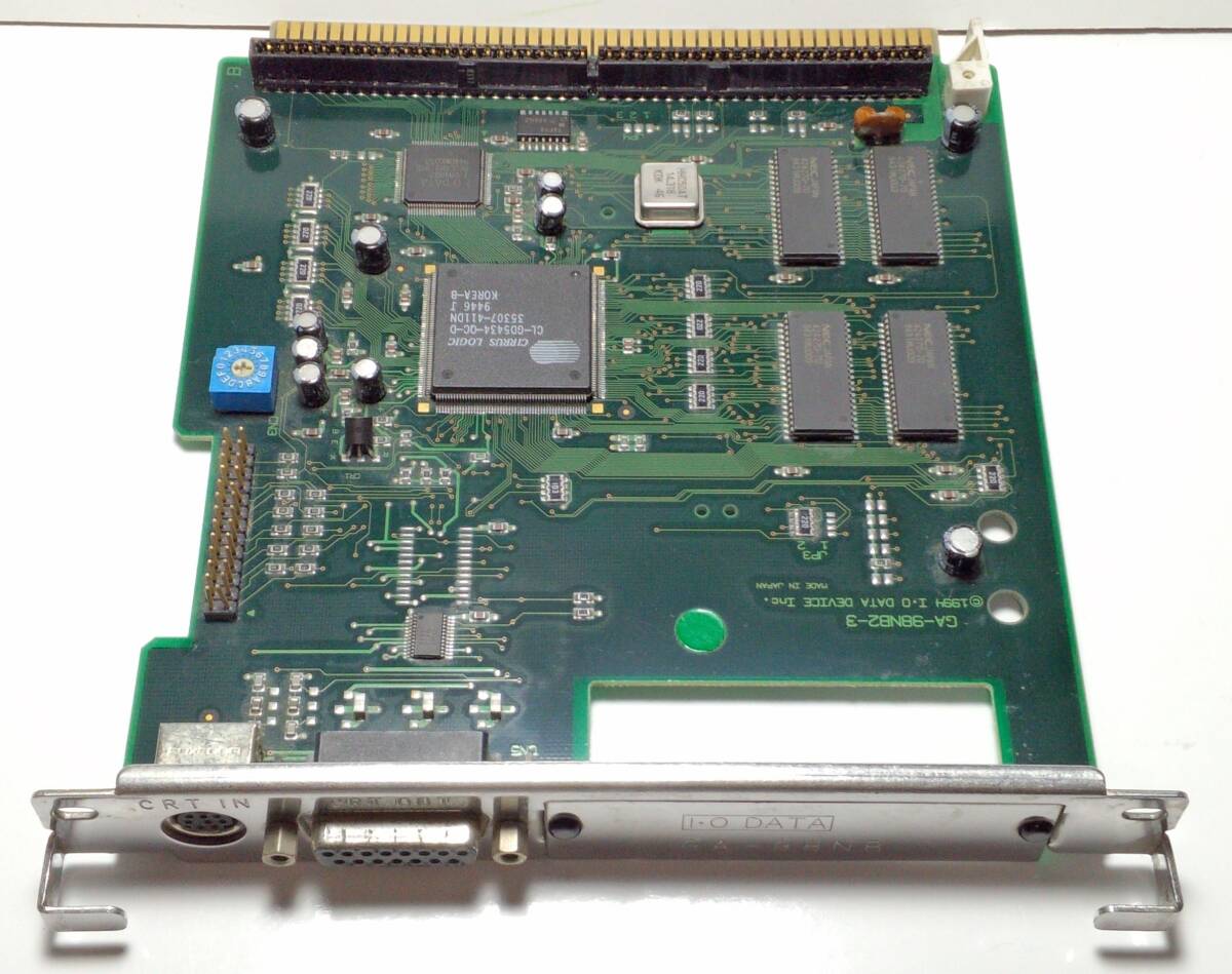 |
IODATA GA-98NB2 郵送無料 PS3-11 | Cirrus Logic graphics accelerator |
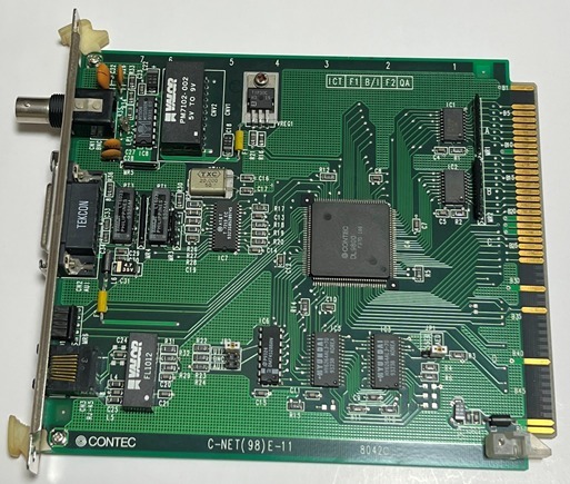 |
PC98 Cバス用 インターフェースボード CONTEC コンテック C-NET(98)E-11 LANボード | LAN Card |
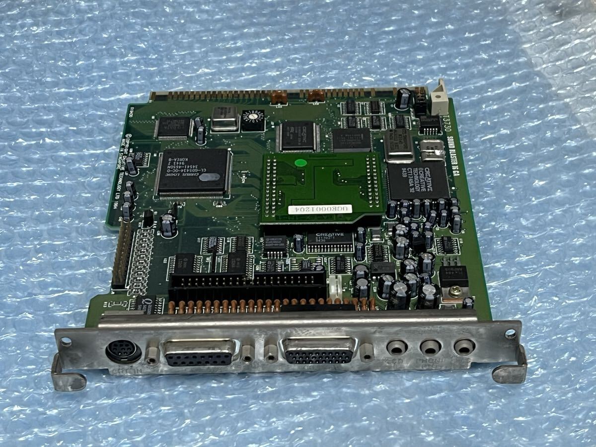 |
■Creative サウンドボード+グラフィックアクセラレータ CT3730 SoundBlaster 16GA【VRAM 2MB】 | A soundblaster for a PC-98! |
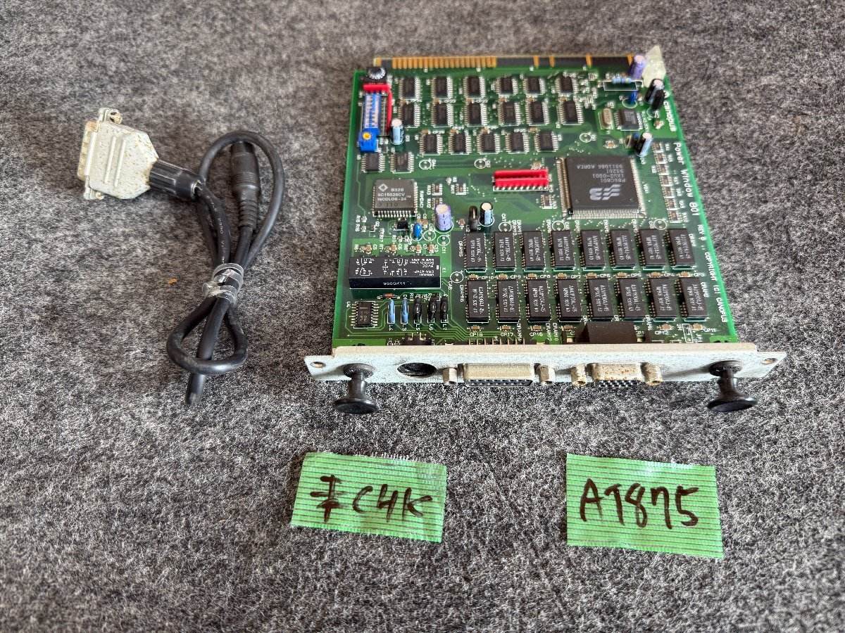 |
【送60サイズ】Canopus Power Window 801 REV B Cバス用グラフィックアクセラレータボード ※未チェック | An s3-based video accelerator |
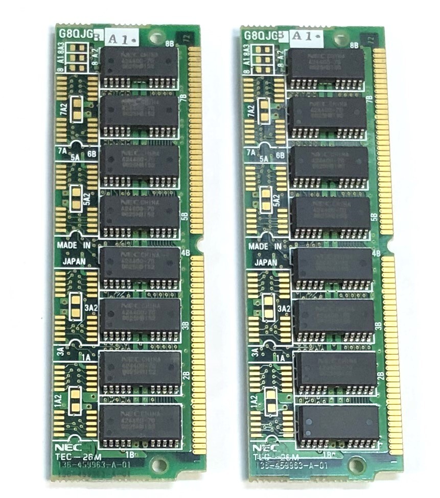 |
◇NEC 増設用メモリ TEC-26M PC98用 2枚セット | Some RAM for the PC-9801FA |
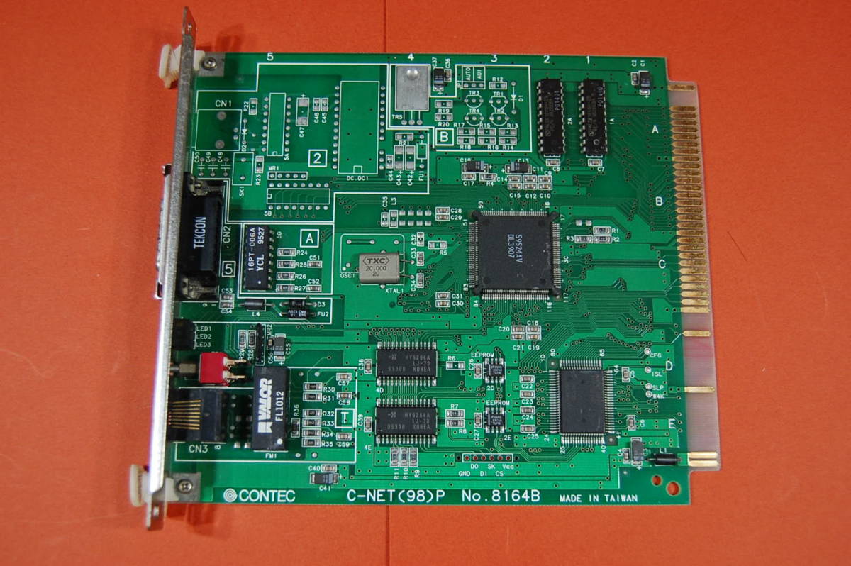 |
PC98 Cバス用 インターフェースボード CONTEC C-NET(98)P No.8164B LANボード サビ有り 動作未確認 ジャンク扱いにて 0343-0892 | Another LAN card |
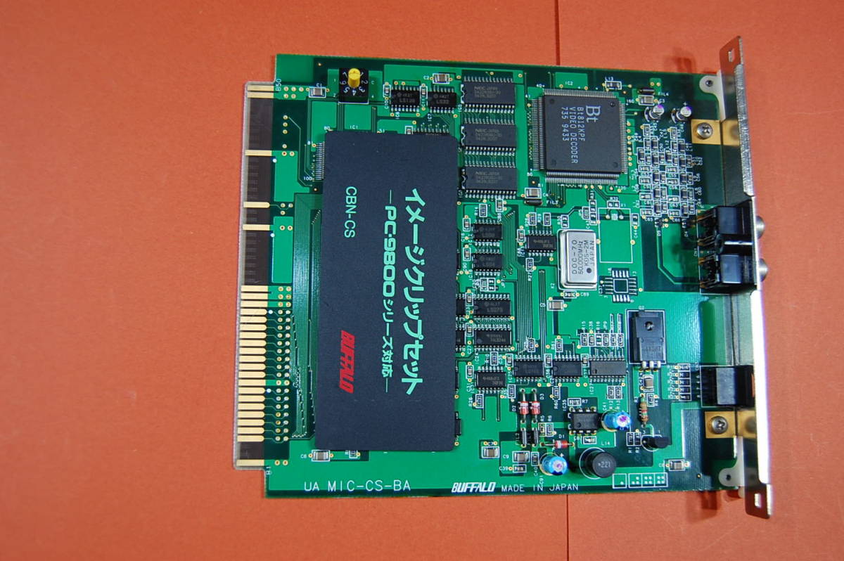 |
PC98 Cバス用 イメージクリップセット BUFFALO CBN-CS 現品のみ 動作未確認 現状渡し ジャンク扱いにて 3545 | Another LAN card |
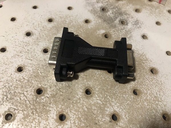 |
動作確認済 ネジ交換 モニタ変換アダプタ DSub15ピンオス-ミニDSUB15ピン(VGA)メス PC98 X68k等レトロPCに(CA230226) | A video adapter to standard VGA pinout |
 |
NEC PC-98用 グラフィック アクセラレーターボード ジャンク | Another Cirrus Logic video accelerator |
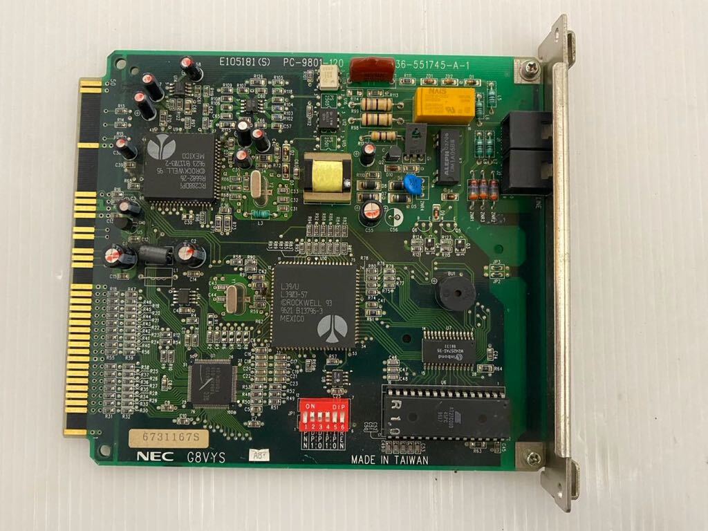 |
【中古】NEC G8VYS E105181S PC9801-120 管理番号ci434 | A modem, just for fun and future projects. |
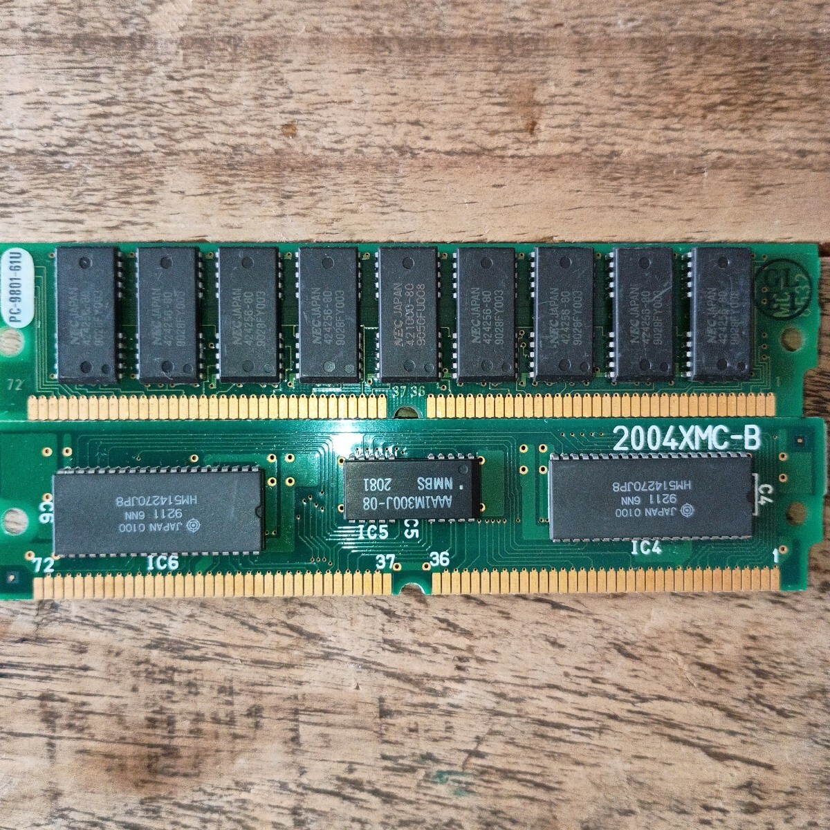 |
メモリ 2004MC - B PC-9801-61U | Some more RAM for the PC-9801FA |
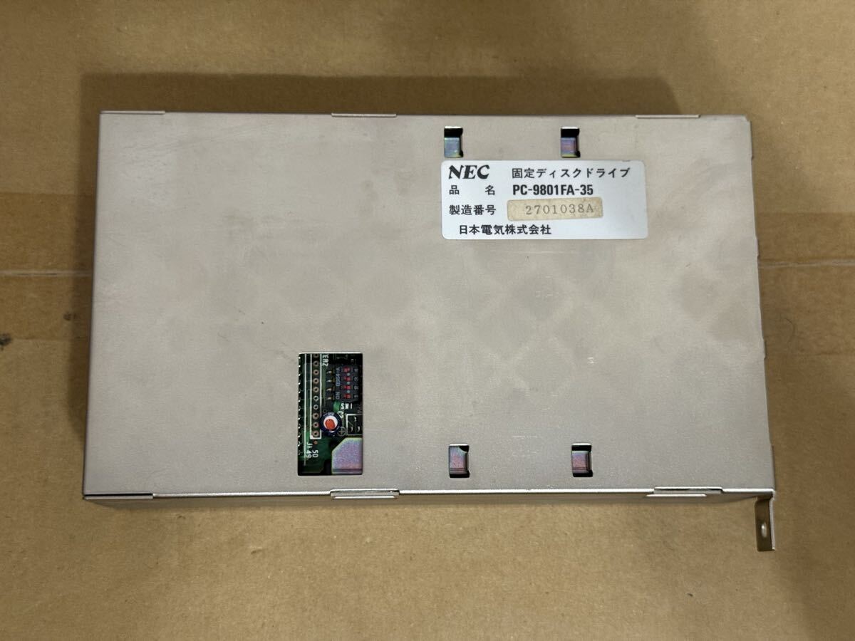 |
【DOS6.2で動作確認】PC-9801FA-35 PC-9801FA,PC-9821A A-MATE用SCSI HDD 100MB | An internal SCSI HDD for the PC-9801FA! |
It all looked great. Buyee had taken all the initial funds for the bid amounts and then consolidated my shipment. They then asked for the EMS payment and I sent that through also. It must have been at the 11th hour, when filling out the customs forms, that they realised they didn't know a $#%$#$% thing about electronics.
I received the following email:
Dear Customer,

This is the Buyee Customer Support.

Thank you for using our service.

We would like to inform you that your package【H2509179102】contains prohibited item for international shipping, which makes the whole package unable for overseas shipping.
-----------------------------------------
Order ID:【R25090402512
R25090302257
R25090402351
R25090403314
R25090403448
R25091004012
R25091100690
R25090902556
R25091302034
R25091504863】
Prohibited item:【Semiconductor】
-----------------------------------------

Please kindly choose one of the following options for your package:

OPTIONS:

I. Dispose of prohibited items that cannot be shipped, and send only the remaining items overseas.
(*If unopened, I agree to open and proceed with the necessary processing.)

Ⅱ. Ship all items in your package to a domestic (Japanese) address, such as your friend's address.

Ⅲ. Divide your package, ship the prohibited items domestically, and register the remaining items into your My Page as normal.
I knew a similar modem listed had a "you're unable to bid on this" banner, but everything I bid on I was allowed to purchase. Buyee already had my money and they'd bin everything if I didn't work out an alternate option? WTF?
Hello,
It is impossible that computer parts are prohibited. Can you please explain where this rule comes from?
Steven.
They took 24 hours to respond with...
We apologize for the inconvenience this has caused you.

Regarding your package number [H2509179102], we would like to inform you that semiconductor is prohibited by  the Japan Export Trade Control Order.

In addition, please be informed that all semiconductor products are considered prohibited items, except for commercially available pre-assembled laptops and desktop computers. It is extremely difficult for Buyee to determine whether products used in assembly (graphics boards, motherboards, conductors, audio equipment) require or not permission for export.
Semiconductor products? INCORRECT. I get that Japan doesn't want to export semiconductor-manufacturing items, of which it's blatantly obvious that these components are not, but how can they get these rules so wrong?
Thank you for the further information. Can you please provide a link to the actual laws from a Japanese government website? I'd like to learn more. Especially to know since when this law has come into effect.
Also, if you look at my account and purchase history on Buyee, I've been buying things like this for decades! I love vintage computers and there has never been an issue in the past. All items are always finished products and maybe only available in Japan, but definitely there are machines in Australia that use these parts.
Finally, this must be causing a lot of frustration with customers since we haven't been told of these new laws coming into effect and are allowed to buy things via your site and then lose all our money?
I would love to work with your team to get items certified so that we can continue.
They came back with a blanket statement...
We understand the importance of this matter to you.

In line with this package [H2509179102] we regret to inform you that the following items below are prohibited for international shipping:
* Semiconductor manufacturing equipment
* Semiconductor substrates
* Semiconductor devices for power control

The above-mentioned legal restrictions apply to a wide range of products, so products not listed here may also be subject to the restrictions.

For more information on the Export Trade Control Order, please refer to https://www.japaneselawtranslation.go.jp/en/laws/view/3389
Again, the rules apply to "raw materials" for semiconductor manufacturing and not completed modules for PCs! It's really sad that they don't have staff onboard who can determine the difference.
Hi again and thank you for the quick response.
Can you please confirm which items in package H2509179102 are prohibited?
This way I can understand to split/destroy/send domestically.
For future purchases, it would be helpful to understand how to determine which items would be prohibited in this category:
https://buyee.jp/item/search/category/2084045751
NO RESPONSE! And so I just sent it to a domestic address where it waits for me to grab on my next japan trip.
So, they answer is... if you can see green PCB in an auction listing, then Buyee will let you buy it, only to then tell you it's illegal and that you can't have it. The fact that they threaten to throw it in the bin, if you can't work out how to send it domestically in Japan, makes me a little sad.
Of course, this is the internet and people have already dealt with this problem before. Buyee even has a prohibited items list, of which semiconductors aren't listed. Even funnier, if they were, I'd disregard it as what I'm trying to buy are FINISHED COMPONENTS.
Even funnier, the law seems to be targeted at China and shouldn't even apply to us lowly nerds just wanting to upgrade our vintage machines!
And It Gets Worse...
I thought I'd try my luck and ask them about a listing. I'm after another PC-9801-86 sound card...
We highly understand the importance of this matter to you.

Regarding the auction [https://buyee.jp/item/jdirectitems/auction/j1208451738], we have confirmed that the auction is not blocked. However, we regret to inform you that we are unable to ship this item internationally due to the presence of a capacitor, which classifies it as a prohibited item.

Capacitors can pose significant safety risks as they may be flammable. In particular, liquid-filled capacitors can leak or burst, while solid capacitors may ignite and release smoke and harmful gases if they overheat or fail. These hazards could potentially lead to fire or explosion.

We appreciate your understanding on this matter and apologize for any inconvenience caused.

Please do not hesitate to contact us if you have any other questions or concerns.
Honestly. That is just icing on the capacitor cake.
Sharp X68000 CZ-612D Monitor Replacement Control Cover
Is it called a flap? A cover? A panel? I saw this X68000PRO unit in Japan on a trip in ... 2023? I found it on the shelf at Super Potato in Den Den Town Osaka with stickers all over it saying it was "for decorational purposes only" and that it "didn't work".
It's not visible above, is it? Sure, I forgot to take a photo of "before I purchased", as I managed to get it carted to Australia for a nominal fee, after being warned that it would really only sit on a shelf and do nothing. Since then I'd managed to get an external HDD going and other software, but I still really need to sit down and re-do all that, blogging at the same time since none of it was easy!
Anyway, the whole point of this post is that, as above, you can see the controls on the monitor. You're not meant to be able to, since there should be a fold-down cover.
This has perished, as many of them do, and I've been on the hunt for two years for a replacement. With nothing turning up in searches, I decided to try and TinkerCad it myself.
Look at that horrible mess? Fortunately, after you group it all, this comes out...
Ok, not bad. You'll note that nothing on the model should be a flat surface. This would've been so much easier if it was a 1084 Commodore monitor flap. Instead, Sharp, in their infinite wisdom (and beautiful design asthetics), decided that the entire bezel should be on a slight curve. Even the base should be curved... and I didn't do that. My CR6-SE printer isn't up to the challenge.
After around 15 attempts/adjustments/refinements/re-measurements/re-adjustments... I managed to produce this...
And you know what?
It's not 100%, but it works!
Here's the 3d model files if you want to print this yourself. I can also print one for you (even in beige!) if you need it. Looking at the list of x68000 monitors, it seems like this'll fit most of them?
Building an ARCNET (also Pure Data PDI 508+)
No, not an ARPANET, an ARCNET. I was recently given a box'o'junk from a friend who was cleaning up a telco engineers house and, honestly, had no idea what I was look at!
Turns out that it's a box full of ARCNET cards and some patch panels. Tiny 8-bit cards, longer 8-bit cards, huge 8-bit cards and even some 16-bit cards! A lot of them are Pure Data branded. Another name I'd never heard of... I did see a bit of SMC though!
I then went down a rabbit-hole of research... with everything seeming to indicate that these cards will simply work as the physical layer to whichever protocol you wish to run on top... so... let's try it!?
The Machines
First up we have a Toshiba T3200 286 Laptop. This thing has an 8-bit and 16-bit ISA slot in the rear, and the usual IEC-13 power plug. Quite the beast. Although it's old and tired, it'll work nicely with Microsoft LAN Manager. Turns out the drivers are already there!
Next up is a 486 DX4/100 and a P2-350. These are the usual desktop workhorses for writing floppies and testing old hardware. They've been sleeping for a while and are quite buried... so it'll be a bit of work to spin them up and test things.
SMC ARCNET PC270E
I chose this card as the first test article. There's a few in the box and they have the least dipswitches of all cards (that have dipswitches) that aren't PNP?. Turns out there's also a one-size-fits-all driver for this card and it's included in all systems I tried.
2. PC130 (SMC 8-bit driver): Newer 8-bit SMC boards with SMC90C63 controller
   chips use the PC130 family workstation driver. RXNET and TRXNET drivers
   can also be used. Boards in this group include the PC120, PC130, PC130E,
   PC220, PC260, and PC270E. The PC130 driver is a workstation only driver.
   If you wish to one of these boards in the server please use the RXNET
   or TRXNET drivers.
Being dipswitch-based, the jumper settings can be found here. Note that 0 is ON and 1 is OFF. That really confused me and I kept configuring the switches in the reverse order; wondering why nothing was working.
With a card in each of the machines, I started hooking up the cabling was exactly the same as an Apple LocalTalk network. RJ11 cables between nodes (any port on the cards) and terminating resistors at the far ends.
After setting some static IPs, I could ping from PC to PC! Unfortunately, the MSLANMAN 2.x installation on the 286 wouldn't ping in either direction.
SMC ARCNET PC260
This card works with the stock drivers but, with the driver installed, Windows 95 started to actually lag. Window and control re-draw rates slow right down, but the card still works. I can only really recommend using these in DOS or lower?
Although I did also try with Windows 98 and it worked fine... so it may have just been an incompatibility with the DX4/100 motherboard and/or resource settings.
PUREDATA PDI507
This seems to be very similar to the SMC above. It also includes BNC for when you don't feel like stringing RJ11 around the house.
PUREDATA PDI508+
This was a can'o'worms. I couldn't get a response from the card in any machine I tried. Windows has the drivers for these cards by default, but they always just showed up as driver failed to load.
There are hardly any settings, as it seems this is a very early PNP card!? Amazing... but frustrating as this EISA configuration document indicates that we need a custom configuration app to configure the settings:
Select desired Network Operating System or General Use to obtain valid hardware configuration options.
PDI508 ArcNet provides a configuration file CFGI508.EXE that will set all memory, I/O, and interrupts (also set through jumper JP2).
Oh great... well... I'm sure this blog will become the first (and only) hit for CFGI508.EXE on the web... as it's lost to time. Or is it? Turns out there's currently an auction for a 5 1/2" disk with, I assume, that exact configuraton app on it... but it's exorbitant. Then again, it's not like I haven't scoured auctions to find configuration apps before.
What is hilarious though, is that this auction has photos of the manual... and I stole them:
Hah.. look at that... default settings! Of course, it's the exact default of the earlier PureData/SMC cards.
| Option | Default value |
|---|---|
| Memory Address | 0xD000 |
| I/O Base Address | 0x2E0 |
| IRQ | 2 |
| Node Address | 0xF0 or 0xF1? |
| Response Time | 74us |
But how, you may ask, do we get the default settings to apply? Turns out there's a jumper on the card to clear the settings! stason.org to the rescue with the board layout! I assume it's a bridge-jumper and boot to clear... then power off, remove bridge, power up and go.
And well, it just worked with the default settings. Perfectly! But, you know what? I want the software... so I bought it...
and...
Yey! The files! I backed it up straight away. The configuration app works in the laptop... but not on the Windows 98 Dos Prompt. Either way, I can re-configure cards now!
And here are the files:
- An archive with two versions of the disk and a folder containing the contents
- The manual as a scanned OCR'd PDF
And finally, ACHEIVEMENT UNLOCKED: I've uploaded all of this to archive.org!
Nostalgia – Complete: 601 FX Martell Advertisement
I'd recently done some archeology to find cover CDs from my childhood. After working out the first challenge and finding the executable/animation on the Walnut Creek CD, I started scouring PC User CDs thinking that I could find the second animation I was after.
Turns out I was barking up the wrong tree... as another tree had made other paper into another magazine known as computer arts interactive. I was hoping to link that title to some kind of article describing their history, but nothing exists! Anyway, I was browsing eBay and saw a mildly familiar CD art design and realised that I must have bought one of the first editions of the magazine back in '95. It wasn't until stumbling upon Vintage Keepsake's site that I realised I knew the CD my animation was on:
That top-left CD was it. The listing had me worried at first, but the price was for the bulk set. They came in quick order from only a few KM away, and only mildly cracked. Fortunately, none of the discs were damaged!
I imaged the CD and slapped it into 86box. From there, I was presented with a very familiar splash screen and muscle-memory allowed me to find the video very quickly!
Ah, it's revolting. 320x240px? But that's what I remember! Actually... the next video is what I remember. I didn't dare slap it into Youtube as it'd hit (at least) 3 copyright flags.
Here's the video from the Youtube video, as-is.
And here's ground-breaking technology showing off Toy Story, which was still to be released.
Now to ISO the rest of the CDs and keep them preserved!
IO-DATA CDBOX
I found this at Beep in Akihabara in the junk pile whilst in Tokyo a few weeks back. It had a label saying "No Power", but I couldn't resist after all the effort I'd spent in the past on 110-pin junk for PC98.
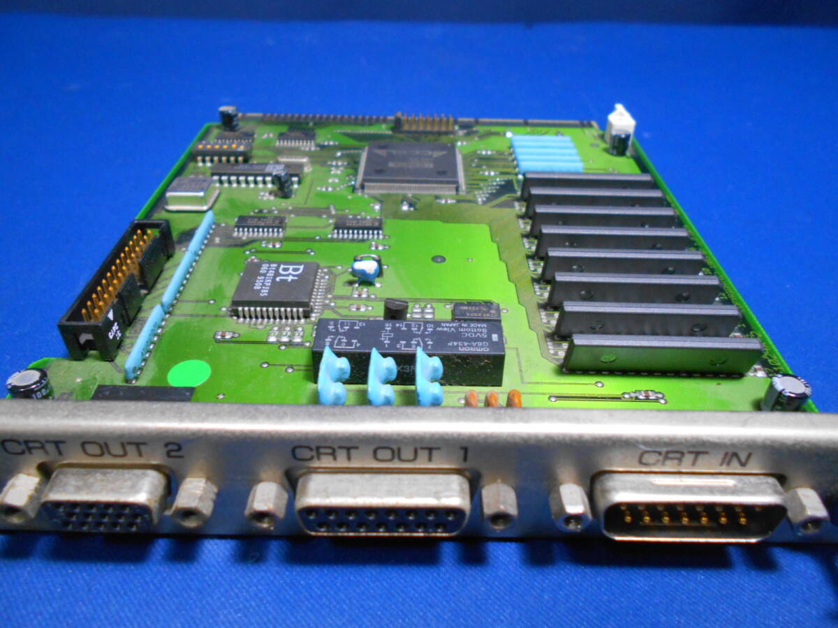
At first glance, it could just be a box containing an CD drive... but flipping around to the back shows some interesting ports! CRT in and out seems to imply there's a window accelerator inside? There's also a C-BUS slot!
The switches underneath definitely indicate that there's a window accelerator. Opening up the unit shows that it's Cirrus Logic-based.
No Power?
The power supply inside smelled fishy, so it was (at least) time to replace some capacitors. I removed and re-inserted a few of the caps, as they didn't seem too bad. I replaced three that I felt were suspect, but the daughter-board only let out a sad squeak/sigh when power was applied.
The wiring between the power supply and the main unit seems to have 12v, 5v and a blue line to power up the relay which is probably something like a power-good signal. The voltages were all non-existent... so I decided to go the sneaky route.
Thanks to PC-standards, we know the pinout of the molex power to the CD unit, so let's just use a splitter and inject +12/+5v there via a Pico ATX supply.
Ok, it works. The LED even lights, meaning the power is flowing into the bus appropriately from this connector!
Installing It
In true IO-DATA style, the drivers are still available on their site. And, of course, in true IO-DATA style, the archives only contain updates to disks you're already meant to own. Fortunately, the archives can be expanded in 7-zip. Inside you'll find all the drivers you need.
The Matsushita version of the CD-ROM Driver was installed (there's a Creative driver there too!) and the Atlas CD was read...
To the point where it even wanted to install...
Using the original power supply
I heard the relay on the board switch when the attached notebook was turned on. It then occurred to me that the "junk" "no power" status was probably a lie. I bet the shopkeepers had just plugged the unit into the wall and not actually tested with a laptop connected. It turns out that the laptop needed to be connected AND powered-on for the relay to throw and the power flow from the internal power supply. Otherwise you'd get nothing. If you do have a totally dead power supply, this is the pin-out:
Note that 5v is on the orange wires and gets two wires. 12v is the red wire and only needs one wire. Finally, the power supply is switched by the blue wire. When the power supply sees the -12v from the Notebook then it'll engage and provide +5 and +12.
Cirrus Logic 98 Graphics Accelerator
This 'just worked'. Doom 2 has drivers for it already, so it was a matter of choosing the right one and booting in.
Excuse the image quality!
Nostalgia: Two Animations From The 90s
I don't know where to start... was it the eBay auction for a cheap DX4/100 in Canberra, perfectly timed to end the weekend that I was in town... or the random discussion of what olive-oil-naming conventions ACTUALLY mean, at work, that lead me to remember a random video on a random cover CD from the 90s that lead me to try and think of the brand that sponsored that 3D animation demo on a CD from the past that I've long lost and long forgotten?
Either way, here are the two vivid memories, of two pieces of animation from the family 486 DX2/66, purchased from Harvey Norman Fyshwick (even though Woden had already opened, replacing Normal Ross, when it was above The Model Shop... damn I miss that shop and thank you for repairing (removing the track nail from the electric motor's brushes) my HO Scale Hornby Maroon Princess Elizabeth which I bought at a basement-bargain price from Mr Odd, father of David who lived off McTaggart Crescent in Kambah back in the 1990s when we went to St Anthony's and... well... he also had Load Runner going on his Apple II which I drooled over.. but he also wanted to sell me a full Candy set Lima XPT in HO which I have also just been recently re-buying) on a 24-month loan from let-us-take-all-your-money-if-you-fail-the-interest-free-period shitty finance company.
Can you believe Gerry Harvey is still going and still offering the same shit? No computer repair corner though... where we took our copy of Free DC which had already been virus-trashed...
I do believe I might have digressed.
The mission today is to find two animations which are most-possibly lost to time...
- The first is something that ran on Windows 3.1+. It was an EXE and was literally a demo app for windows. An encapsulated animation in an EXE that ran when you executed it, took your whole screen... played the animation and then returned you to where you were prior. This is what I remember:
- A red parrot is flying on a blue sky background (no clouds) left to right.
- It is a simple cartoon animation and it has a yellow beak.
- From the right, a bi-plane zooms in, chews up the bird and just the beak is left.
- The beak then falls through the bottom of the viewport.
- The credits scroll and the authors are Huon and Maverick.
- The second is a sepia-toned 'birds-eye view' of a bird flying into a spanish/greek vineyard/olive-plantation, discussing the qualities of the olive-oil/wine that the company produces. It was a movie file (not an EXE!) sitting in the videos/movies/demos folder on a magazine cover CD. Maybe it was quicktime? But I think it was AVI as I don't recall codec issues when watching it. Either way, the hints are:
- From a Cover CD from an Australian Magazine in the 90s.
- Sepia-toned landscape, dry, vineyard/orchard ... somewhere middle-europe.
- Following right on the tail of a bird (maybe a swallow?)
- Either an Olive Oil or Wine advertisement.
- It's actually meant to showcase the video compression technology, fitting on a Cover CD with all of the other bloatware.
- The brand could be: Martelli, Martell, Mortell
Update: The second animation has been found!
With all of this in mind, I started scouring the web. I quickly landed on the APC Mag Cover CD Stash on Archive.org. Sheesh, I definitely bought a few of those mags and used their CDs... but they didn't have what I was after. A quick goog' of "aus mag cover cd" brought me to Australian PC User (now TechLife) and ... woah.. I think I was a subscriber? This was 30 years ago. Am I meant to care/remember? Either way... One of those cover CDs hit me like a sack of bricks. Maybe I wasn't a subscriber and maybe I might have only bought one of those mags from Wanniassa Newsagency with its cover CDs?!
Why do I have this photo? I bought the same fkn Cover CD from eBay 4 days ago. It's all still circulating... But I actually bought it as I want to archive it all. archive.org has a good selection, but it's not as clean-and-tidy as the APC Mag CDs are.
Anyway! The CDs I could find did not contain the olive-oil/wine (herefore known as OOW) demo.. nor the BIRD demo. At this point I was chatting to my Brother, Rodger, who is awake when I sleep in Amsterdam. I do believe I triggered a dragon when I mentioned I was looking for a bird flying on a blue background in Windows 3.1... He proceeded to go for a stroll down memory lane and list the games he remebered from our childhood, but none matched what I was digging for. I thoroughly enjoyed adding to his memory games like Xenon 2 Megablast, but it didn't get me to where I needed to go. One thing though... during his search of nostalgia-ware... he mentioned that I might be thinking of something from "one of those 100000'in'one shareware compilations....".... oh.
Walnut Creek
This actually hit a nerve. At this point I would've written a new blog post asking about a "random shareware operator in the late 90s with a wizard on the cover." and ... well ... I don't expect any comments on this post, let alone a ficticious wizard post. Fortunately, buried in the depths.. I had a hint of "Warlock" software, with a wizard.. then "Walmart".. and then ... don't ask me how, but I came up with "Walnut CD". A quick search of that lead me straight to a suite of CDs on archive.org. Get out of here...
It's that #$%#$%#$%#$% wizard. Time to digress: Back in Canberra in the 90s, we had BitStorm in the Canberra Centre, ACTCom in Belconnen Mall and Boomerang Software in the Tuggeranong Hyperdome. The first sold me Screamer. The second showed us Doom I running on a demo PC in the store and the last sold me countless shareware floppies, Settlers I, a Dreamcast and so much more. Whatever happened, Boomerang Software, when it was in the Hyperdome near The Candy Shoppe and Cafe Rendezvous, was at its peak selling shareware with its own branding. It also had an amazing selection of second-hand software and hardware and I'd check it out every friday night.
It was at Boomerang that I bought a Walnut Creek shareware CD and I could not tell you why... but I'm sure there was something lucrative on the title. The cover art was navy/purple and the wizard was on it, and this was all I had to go by as I had no method to check the quality of the media as the cases were shrink-wrapped. I vividly remember their price-tags being 20mmx20mm and split horizontally. Top half having the current sale price and bottom half showing the price you'd get if you traded the same item in?
Either way... this CD had the bird animation on it. I'm only sure now as I went through the entire ISO collection on archive.org looking for a file with BIRD in the name. I had expected BIRDFAIL or BIRDDIE or BIRDPLANE... but it seems I should have been searching for BIRD_ANM. It was just this name that appeared on the September 1994 version of Walnut Creek CICA Windows Shareware. Interestingly, I don't remember the CD art in that listing's shot... however I do click with the cover art from April 1994.
Regardless, I ripped open the zip archive and inspected the BIRDY.TXT text file...
FINALS WEEK PRODUCTIONS
=======================

PROUDLY PRESENTS THE 1RD INSTALLMENT OF THE "NATURAL SELECTION SERIES"

TITLE: Survival of the Fittest!!
COMPLETED: May 1, 1993
AUTHORS: Jeffrey Cubillos and Alfredo Rojas
Bird, vs. Plane?, Survival? How can this not be it? The names don't match... but... wait... how do we even test this? Install Virtual Box, Install Windows 95...
It'll crash when trying to boot.. so install the "Fix CPU" patch...
And keep fighting...
So, Windows is running... mount the CD and..
It has an interactive text menu? and it UNZIPS THINGS FOR YOU? WHY DOn'T I REMEMBER THIS PART? Screw the animation... this is actually the systems integration part that pays the bills!
Because I'd found the location of the ZIP in archive.org, I knew which folder and which ZIP to extract. It was quickly deployed to C:\
The moment was then upon us... was this the file?
No way. It was. That's it! I got the names slightly wrong and the bird was also flying in the wrong direction... but the rest wasn't far off... at all?
The worst part? It was all of 4 seconds of animation! Those 4 seconds, on a CD-ROM, in ~1994 stuck.. and somehow in 2025 (do the maths.. that's 31 years?) I wanted to see it again... and.. it existed?
.. now to find the other animation! ... but in the meantime, here's the backyard tree that has also had 40 years to grow:
Enjoy.
Random Photos
Search
Tags
Links - Click for details
- Abandoned Rails (Japan)
- AIRLINE (Shinkansen Photography)
- Akihabara Station
- annexpressのブログ
- Australian Model Railway Magazine
- DCC普及協会ホームページ (Japanese DCC)
- Dead Section (Japanese Track Diagrams)
- Delicious Things (Japanese N Scale DCC)
- Densha Wotorou
- Digital Direct for Windows (DCC Server)
- Don's Dream World – AMAZING N Scale Japanese Layout
- Hatena::Diary
- Japanese N-Scale Modeling Forum
- JR Chiisai
- Kaz-T's blog レインボーライン (Rainbow Line)
- LED Resitance Calculator
- Masioka
- Poppondetta Blog
- RailFan Magazine, Japan
- Railmind
- Railway Travelers' Room
- Serenity Valley
- Shashinka Ichiban
- Shuzuku
- Sumida Crossing
- The next station is…
- Tomix N Gauge Track and Japanese N Gauge Trains
- TT Forums (Transport Tycoon Deluxe)
- 名鉄尾西線の貨物列車 (Nagoya: Meitetsu Freight)
- 日本型Nゲージ DCC改造例のご紹介 (Okiraku DCC)
- 泰 茅 轍 道 (Taichi Railway)
- 箱庭登山鉄道製作記 (Hakone-Tozan Layout Blog)
Archive
- July 2026
- May 2026
- April 2026
- March 2026
- February 2026
- January 2026
- November 2025
- October 2025
- September 2025
- August 2025
- July 2025
- June 2025
- February 2025
- January 2025
- November 2024
- September 2024
- August 2024
- July 2024
- June 2024
- May 2024
- April 2024
- March 2024
- February 2024
- December 2023
- October 2023
- September 2023
- August 2023
- July 2023
- June 2023
- May 2023
- April 2023
- March 2023
- December 2022
- November 2022
- October 2022
- April 2022
- March 2022
- February 2022
- January 2022
- December 2021
- November 2021
- September 2021
- August 2021
- July 2021
- May 2021
- March 2021
- February 2021
- January 2021
- October 2020
- September 2020
- August 2020
- July 2020
- June 2020
- May 2020
- April 2020
- March 2020
- January 2020
- December 2019
- November 2019
- October 2019
- September 2019
- August 2019
- July 2019
- June 2019
- April 2019
- March 2019
- February 2019
- January 2019
- December 2018
- November 2018
- October 2018
- September 2018
- August 2018
- July 2018
- June 2018
- May 2018
- April 2018
- March 2018
- January 2018
- December 2017
- November 2017
- October 2017
- September 2017
- August 2017
- July 2017
- June 2017
- May 2017
- March 2017
- February 2017
- January 2017
- December 2016
- November 2016
- October 2016
- September 2016
- August 2016
- July 2016
- June 2016
- May 2016
- February 2016
- November 2015
- October 2015
- September 2015
- August 2015
- July 2015
- June 2015
- May 2015
- April 2015
- March 2015
- February 2015
- January 2015
- December 2014
- November 2014
- August 2014
- July 2014
- May 2014
- April 2014
- March 2014
- December 2013
- November 2013
- October 2013
- June 2013
- August 2012
- April 2012
- March 2012
- February 2012
- November 2011
- October 2011
- September 2011
- July 2011
- June 2011
- May 2011
- April 2011
- March 2011
- February 2011
- January 2011
- December 2010
- November 2010
- October 2010
- September 2010
- August 2010
- June 2010
- May 2010
- April 2010
- March 2010
- February 2010
- January 2010
- December 2009
- November 2009
- October 2009
- August 2009
- January 2009
- December 2008
- November 2008
- October 2008
- September 2008
- July 2008