


 Melbourne BG SCS Train Timetable


Odoriko 185 Series Decoder Install
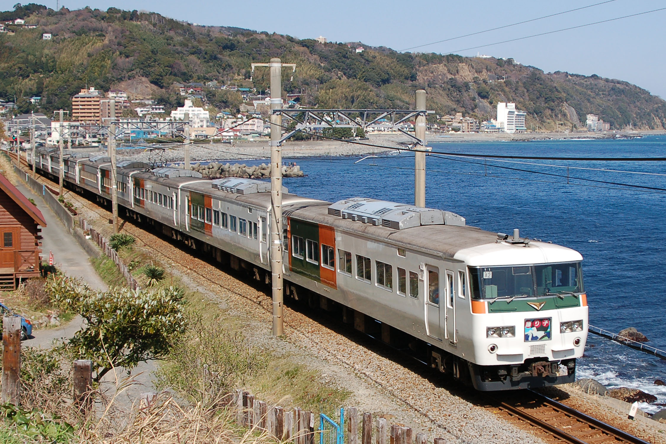
[From Wikipedia:]The Odoriko (踊り子?) is a limited express train service in Japan operated by JR East which runs between Tokyo and Izukyū-Shimoda or Shuzenji.
The limited express service was inaugurated in October 1981 following the introduction of the then-new 185 series EMUs, replacing the earlier Izu express services from Tokyo to Izu. Services are currently operated by 7-, 10-, and 10+5-car 185 series EMUs, making it the longest Limited Express train running in Japan (excluding shinkansen trains).
The word odoriko means a girl dancer in Japanese. The train service was named after the title of novel Izu no Odoriko (The Dancing Girl of Izu) by Yasunari Kawabata. The stage of the novel is the destination of the train, Izu Peninsula.
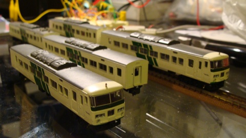
I'd bought my 5-Car Micro Ace Set partially damaged (if anyone can tell me where to get replacement pantographs?) and had opened it up on the first night of running due to severe eletrical issues.
After a night with WD-40 and a soldering iron I had the set doing laps at good speed, but every other day it needed a service.
This all boiled down to the way the motor car connects to the tracks. The bogies both conduct both polarities into the chassis which is split in two and electrically isolated. Unfortunately at the point where the bogies touch the chassis was a lot of grime and damaged parts. It seems there were originally two pins that had been snapped meaning the bogies were very loose.
Anyway... all this meant that the electrical connection in the motor car was next to useless since a constant power source was required for DCC and interruptions would play havoc on the data stream from the rails.
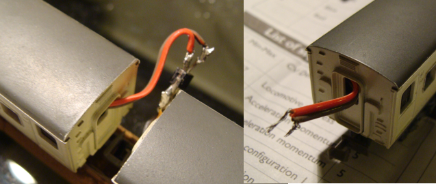
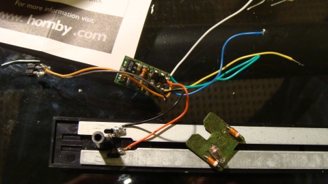
I therefore decided that the best method was to slap the decoder in the end car (meant easier wiring of one set of headlights) and have a tiny cable run through (with a plug) to the motor car... This all went fairly smoothly... but I did have to remove the seating in the end car... I'll look into this again shortly.
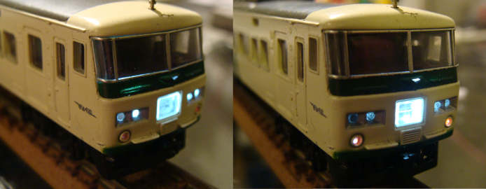
I removed the 12v globes that originally lit up the car with white LEDs and around 1K2 total resistance to get the level of light emitted in the photo below. This was simply two 680ohm resistors in series to the anodes of both LEDs connected to the Blue wire from the decoder. The cathodes connected directly to the Yellow and White wires for forward and reverse. I initially wanted to use the original light circuit but found that bending LEDs to fit in there would be too tight.
Anyway... the end result is a beautifully running 5 car set with directional headlights at one end and to-be-completed headlights at the other end... should I run wires right through all 5 cars or buy another decoder just for 2 LEDs? ...
Random Photos
Search
Tags
Links - Click for details
- Abandoned Rails (Japan)
- AIRLINE (Shinkansen Photography)
- Akihabara Station
- annexpressのブログ
- Australian Model Railway Magazine
- DCC普及協会ホームページ (Japanese DCC)
- Dead Section (Japanese Track Diagrams)
- Delicious Things (Japanese N Scale DCC)
- Densha Wotorou
- Digital Direct for Windows (DCC Server)
- Don's Dream World – AMAZING N Scale Japanese Layout
- Hatena::Diary
- Japanese N-Scale Modeling Forum
- JR Chiisai
- Kaz-T's blog レインボーライン (Rainbow Line)
- LED Resitance Calculator
- Masioka
- Poppondetta Blog
- RailFan Magazine, Japan
- Railmind
- Railway Travelers' Room
- Serenity Valley
- Shashinka Ichiban
- Shuzuku
- Sumida Crossing
- The next station is…
- Tomix N Gauge Track and Japanese N Gauge Trains
- TT Forums (Transport Tycoon Deluxe)
- 名鉄尾西線の貨物列車 (Nagoya: Meitetsu Freight)
- 日本型Nゲージ DCC改造例のご紹介 (Okiraku DCC)
- 泰 茅 轍 道 (Taichi Railway)
- 箱庭登山鉄道製作記 (Hakone-Tozan Layout Blog)
Archive
- July 2026
- May 2026
- April 2026
- March 2026
- February 2026
- January 2026
- November 2025
- October 2025
- September 2025
- August 2025
- July 2025
- June 2025
- February 2025
- January 2025
- November 2024
- September 2024
- August 2024
- July 2024
- June 2024
- May 2024
- April 2024
- March 2024
- February 2024
- December 2023
- October 2023
- September 2023
- August 2023
- July 2023
- June 2023
- May 2023
- April 2023
- March 2023
- December 2022
- November 2022
- October 2022
- April 2022
- March 2022
- February 2022
- January 2022
- December 2021
- November 2021
- September 2021
- August 2021
- July 2021
- May 2021
- March 2021
- February 2021
- January 2021
- October 2020
- September 2020
- August 2020
- July 2020
- June 2020
- May 2020
- April 2020
- March 2020
- January 2020
- December 2019
- November 2019
- October 2019
- September 2019
- August 2019
- July 2019
- June 2019
- April 2019
- March 2019
- February 2019
- January 2019
- December 2018
- November 2018
- October 2018
- September 2018
- August 2018
- July 2018
- June 2018
- May 2018
- April 2018
- March 2018
- January 2018
- December 2017
- November 2017
- October 2017
- September 2017
- August 2017
- July 2017
- June 2017
- May 2017
- March 2017
- February 2017
- January 2017
- December 2016
- November 2016
- October 2016
- September 2016
- August 2016
- July 2016
- June 2016
- May 2016
- February 2016
- November 2015
- October 2015
- September 2015
- August 2015
- July 2015
- June 2015
- May 2015
- April 2015
- March 2015
- February 2015
- January 2015
- December 2014
- November 2014
- August 2014
- July 2014
- May 2014
- April 2014
- March 2014
- December 2013
- November 2013
- October 2013
- June 2013
- August 2012
- April 2012
- March 2012
- February 2012
- November 2011
- October 2011
- September 2011
- July 2011
- June 2011
- May 2011
- April 2011
- March 2011
- February 2011
- January 2011
- December 2010
- November 2010
- October 2010
- September 2010
- August 2010
- June 2010
- May 2010
- April 2010
- March 2010
- February 2010
- January 2010
- December 2009
- November 2009
- October 2009
- August 2009
- January 2009
- December 2008
- November 2008
- October 2008
- September 2008
- July 2008