


 Melbourne BG SCS Train Timetable


Detecting trains with InfraRed + Arduino
You've probably seen a lot of reversing/stopping circuits around, but the majority of these run on occupancy detection in track blocks. This can work very well but, due to the differences in train engines, you can have issues with how quickly to slow/stop individual locomotives. There are other ways of detecting a train coming to a dead-end, and here I'll show a method using Infrared Light.
Infrared light can't be seen by the human eye, but can be picked up by electronic devices. Due to this, it can be used freely around your layout (with the exception that direct sunlight/room-light can cause interference) for detecting your trains. One of the more common usages is to put an emitter/detector combination in a buffer to stop a train as it comes to the end of the line.
Note that there are two emitter/detector devices! Each 'black box' in that diagram contains both an emitter and a detector. The benefit of using the QRD1114 means that these are neatly packaged in one unit!
In this set up the emitter and detector are both facing towards an approaching vehicle. The emitter-side of the QRD1114 will always be emitting infrared light down the track. The detector will then receive the infrared light reflected off the vehicle as it approaches and its internal resistance will rise accordingly. This means we can read the resistance of the detector to know how close the train is therefore slow it down proportionately. We can therefore ensure the train does not hit the buffer by checking the value of the detector and altering the speed of the train quickly and appropriately.
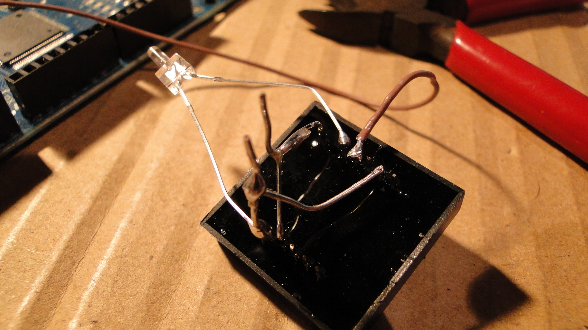
Firstly, here's the circuit for wiring up both the 'Infrared Emitters and Detectors' and the Optical Detector / Phototransistor (recommended) from Toys Downunder. And Here's the datasheet for the latter QRD1114.
Note: I happened to test out both setups as I destroyed my first QRD1114 by applying 5v directly to the emitter... You must only apply 1.7v max!
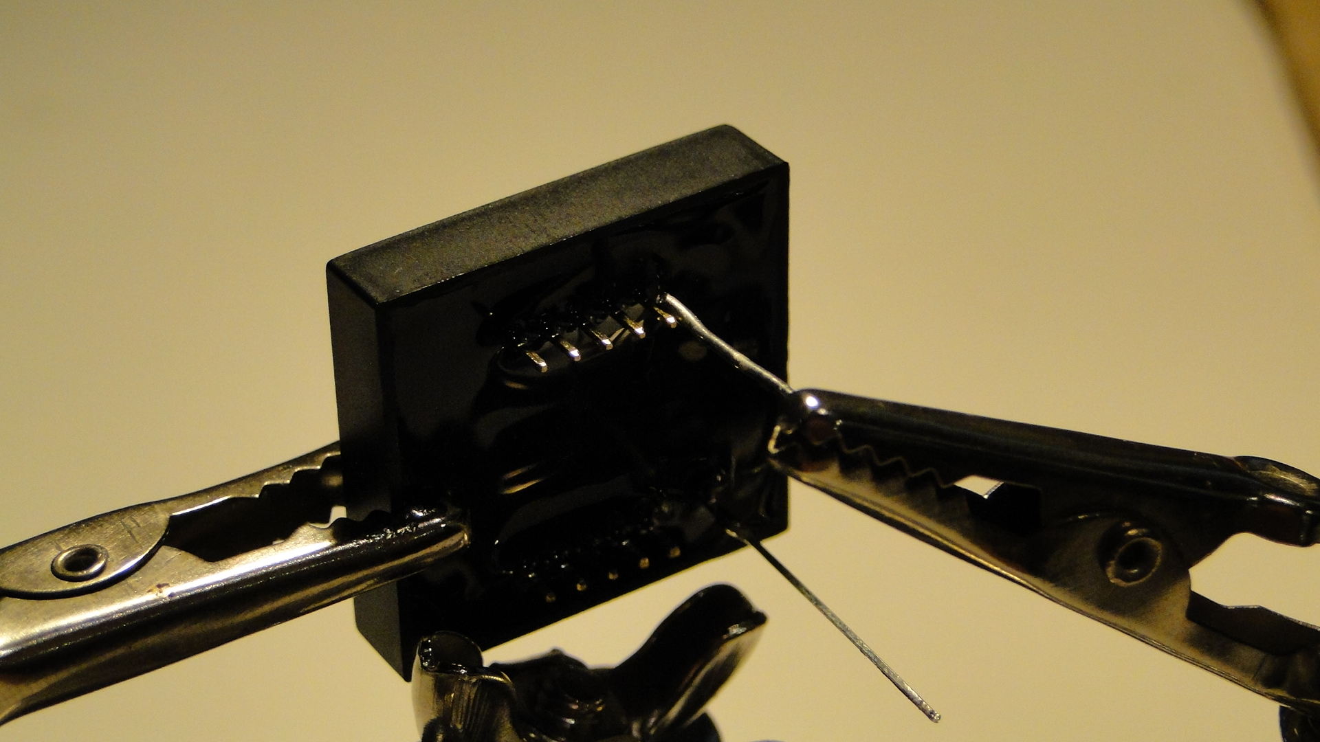
And then the detector set up on the engine shed roads:
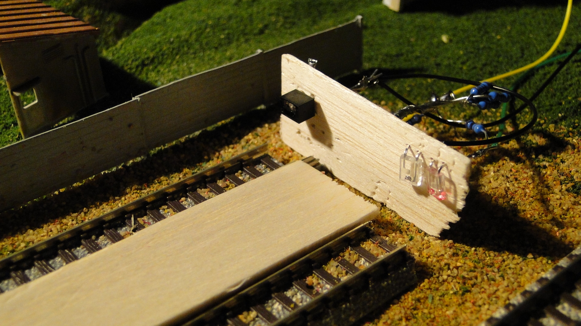
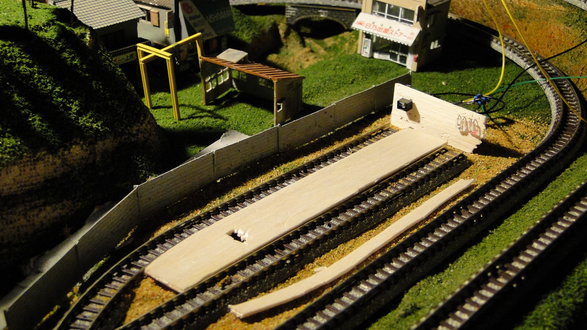
The two roads above will eventually be located inside an engine shed. Due to the potential interference from one emitter to the other, I will put a separator down the middle of the tracks.
The maxmimum read distance I could achieve was just under 6cm during testing**. This wasn't exactly what I was expecting and would've liked around 10-12cm for this purpose, but I worked around this. It seems that there is a more expensive detector at Toys Downunder: Sharp GP2Y0A21YK that can detect object up to 84cm away. I imagine it would be as simple as obtaining larger IR LEDs to boost the light output and therefore the light reflection.
Once the two detectors were in place, I set about automating a quick shunting process. I'd started noticing that, depending on room light, the readers weren't doing the best job; down to around 20mm distance was all that was being detected. This would not be enough to measure the speed as I wanted to, but I kept going anyway.
Programming the detector was the same as the potentiometer throttle done previously. The detector acted as a variable resistor and the reading would be from +1000 to 0 depending on the reflectivity of the object. It turned out that 0 was when the object was closest to the detector. Unfortunately, this only started changing once the object came within 30mm.
Here's a video of my quick shunt automation in action. First with the QRD1114 and then with the separate emitter/detector:
Results
I ended up stopping progress on this as the detector didn't respond as well as I'd have wanted. After getting a 6cm read distance during test I thought it would feasible, but this dropped to a max of 15mm when actually installed on the track. There would be too much re-adjusting to get either of the types of infrared detectors to work.
The only option from here is to purchase the Sharp detector mentioned above and see if it really can detect 84cm!
Tracking trains with an Arduino and RFID : Implemented
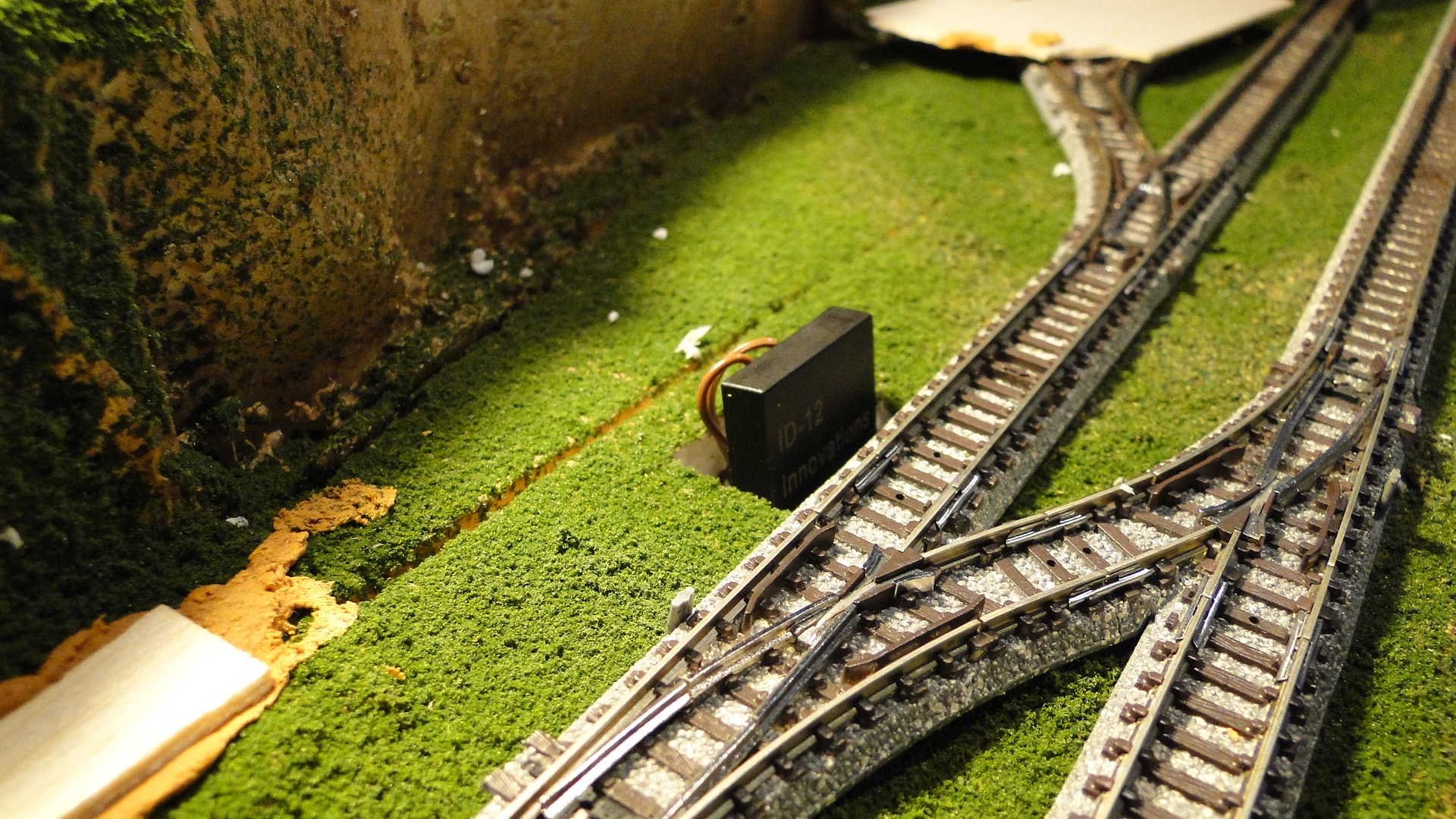
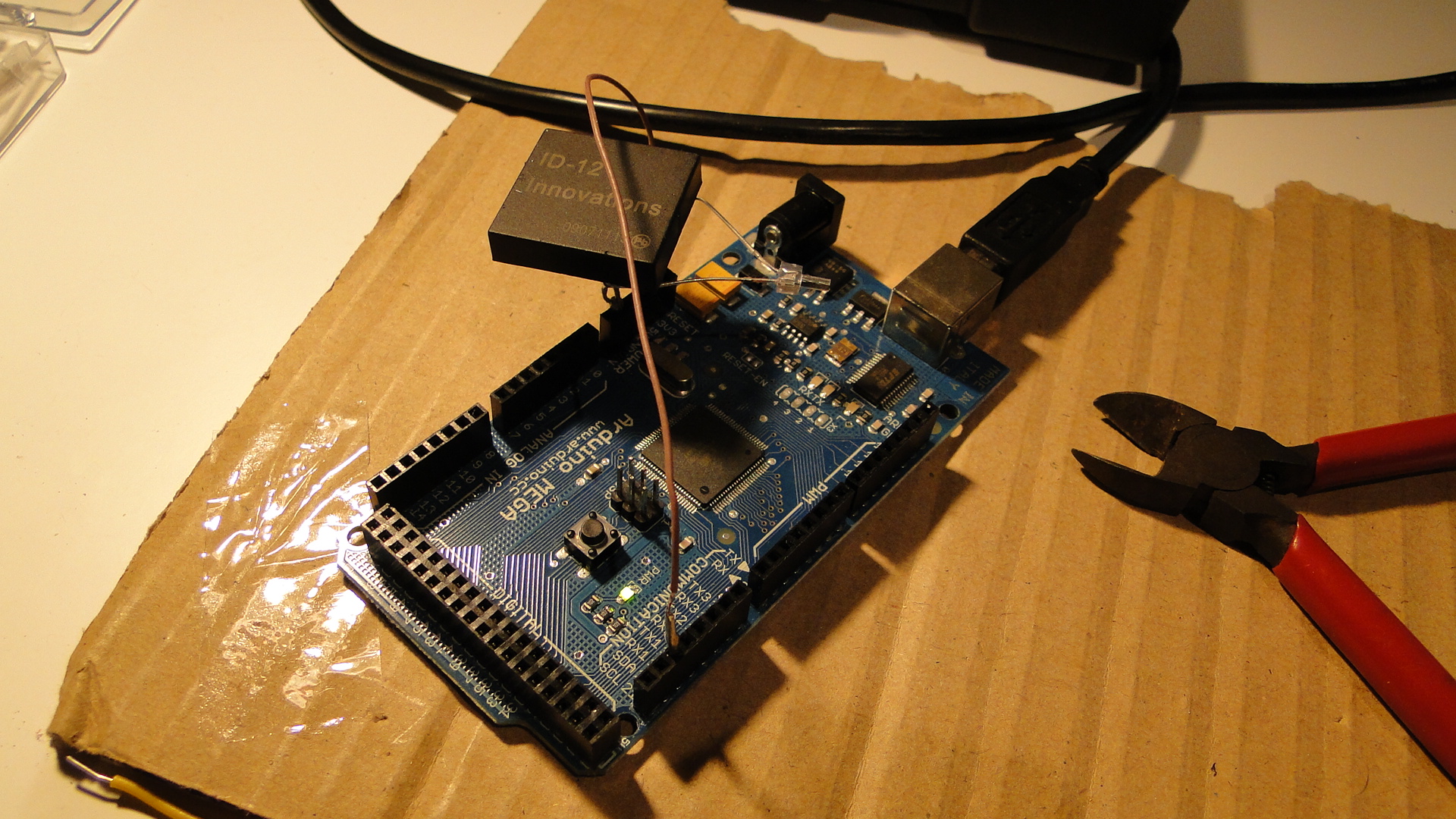
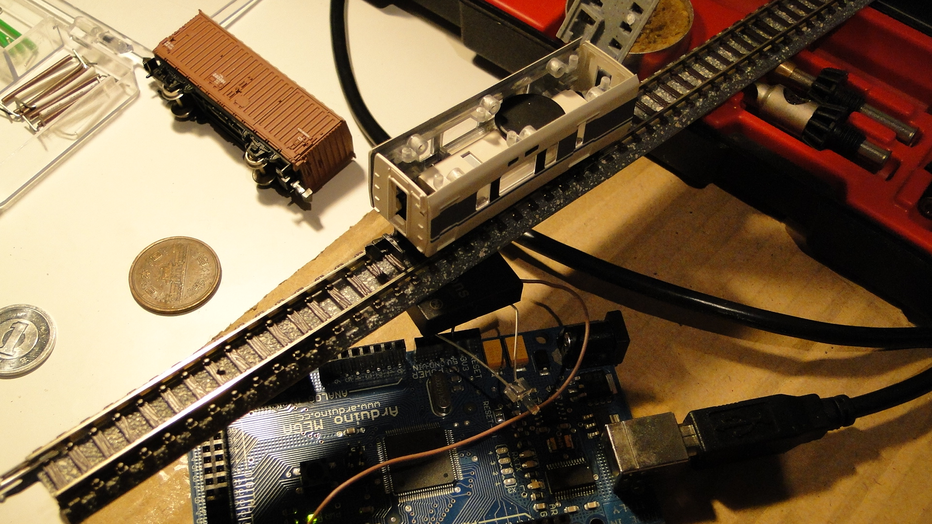
Right, after telling you all about how the RFID setup works (and how to do it yourself), I thought I'd actually test it on my work-in-progress layout. Just for a recap, this setup uses the Arduino Mega, an ID-12 RFID Reader (plus RFID Button) from Toys Downunder and the code provided in the article listed here.
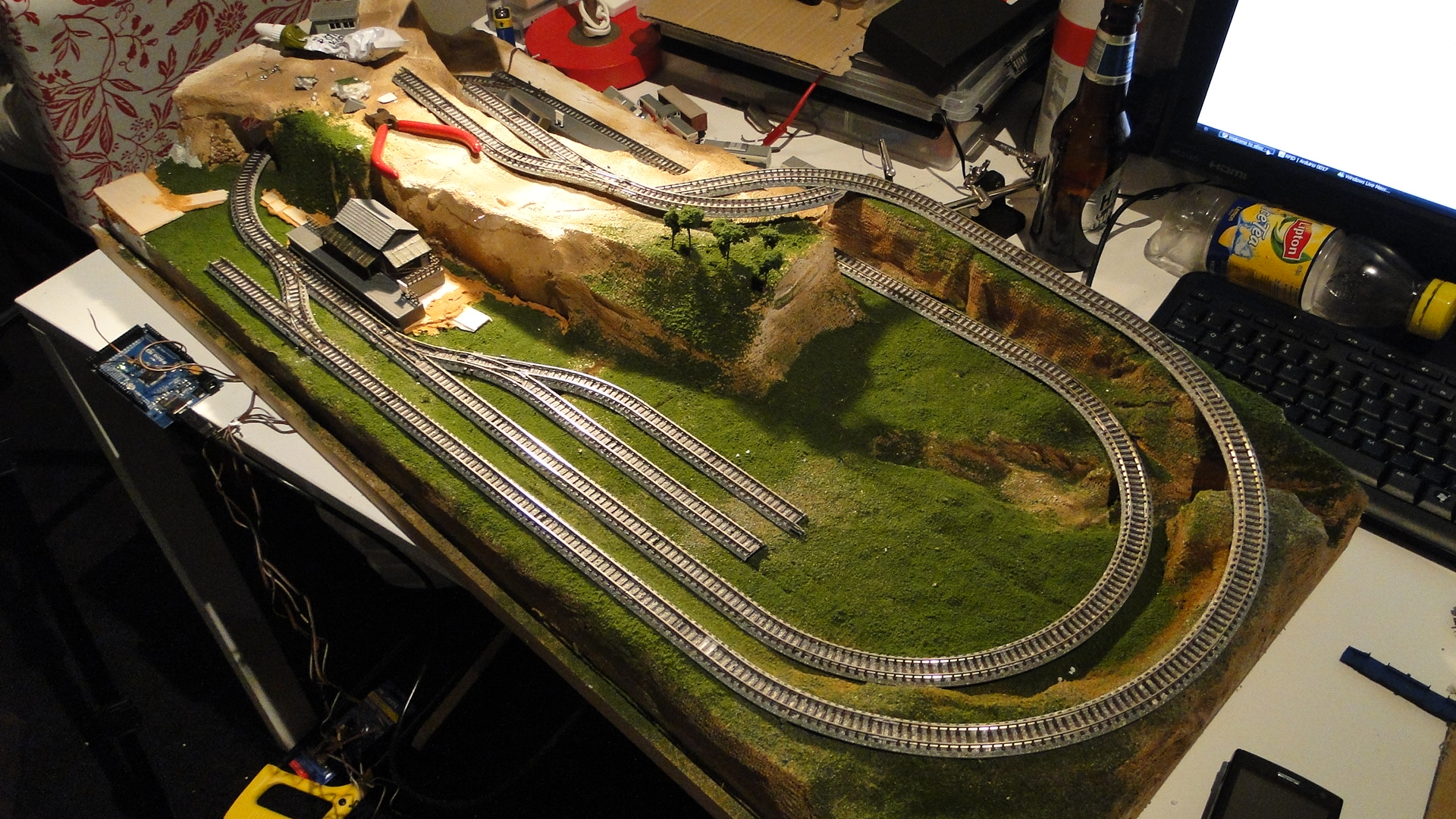
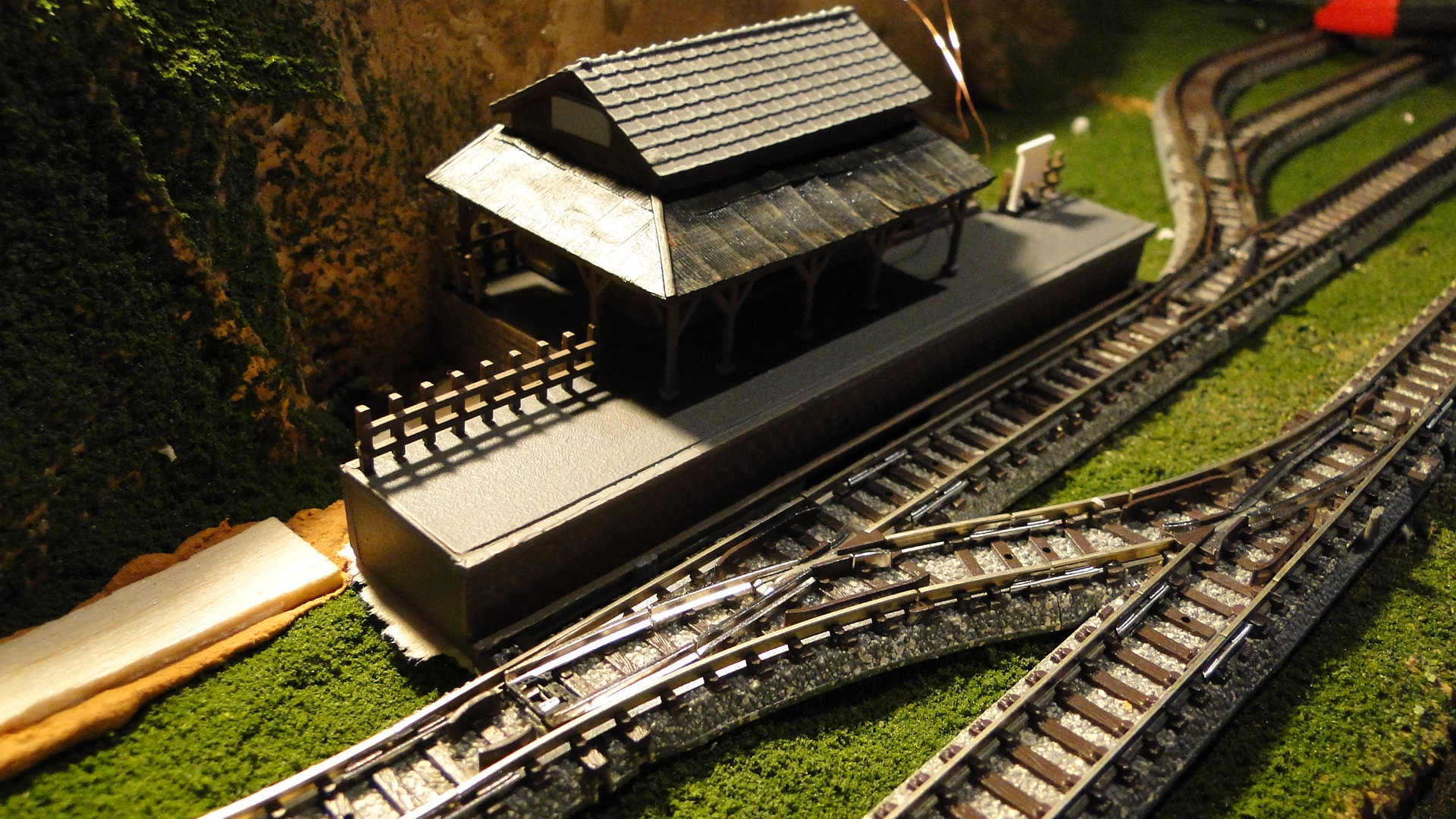
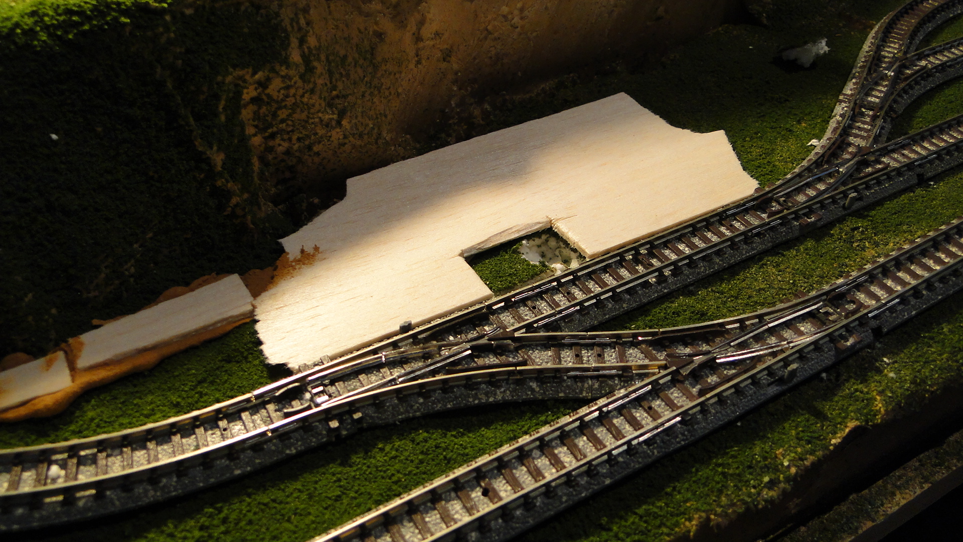
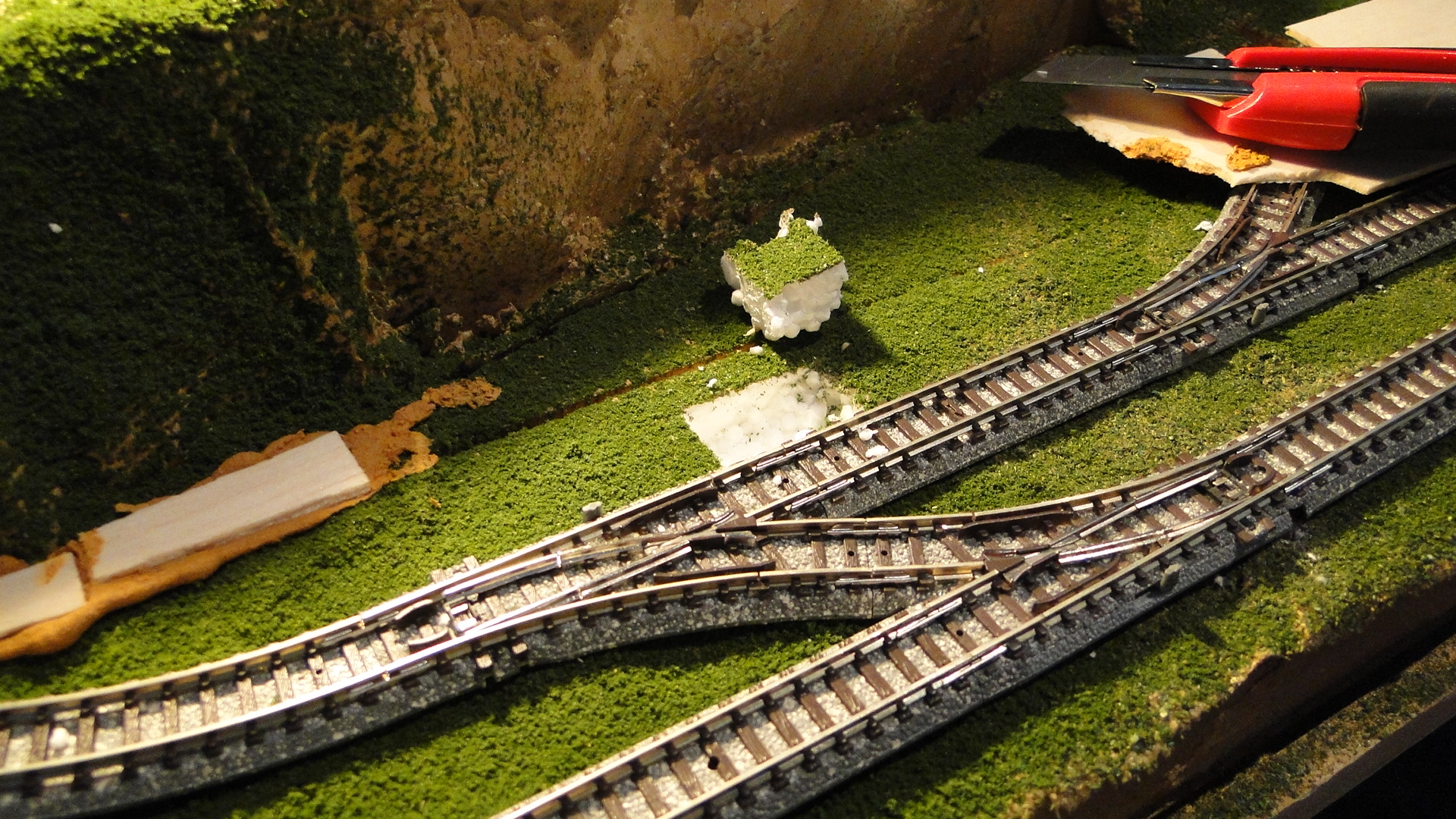
I knew the ID-12 reader had a 60mm optimal read distance, so I wanted it pretty close to the track for extra reliability. I decided on mounting it inside the platform, as it would be close to the track and I could perform actions/events once a train reached the platform.
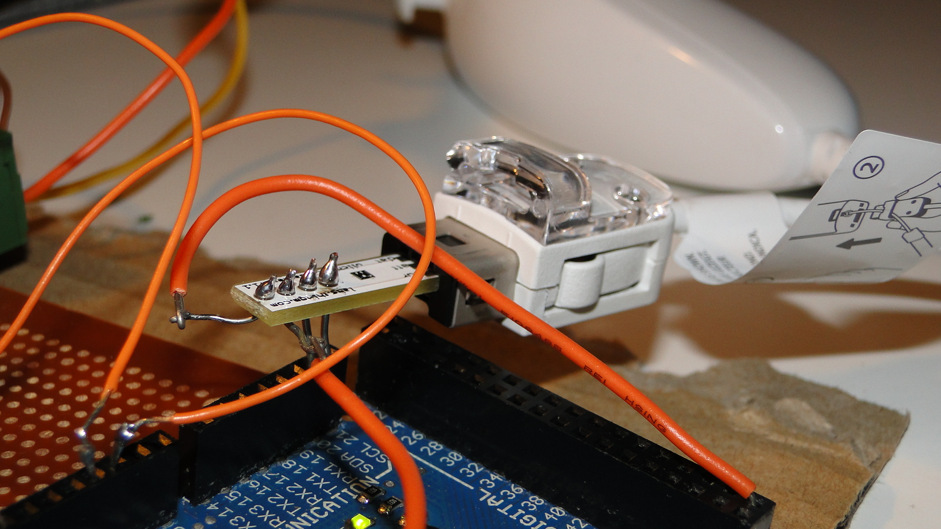
First I had to rewire the reader, as previously I'd used component wires (surplus resistor legs, etc...) so that I could easily test it on the Arduino. Now that it was to go through the baseboard I needed lengthy wires:
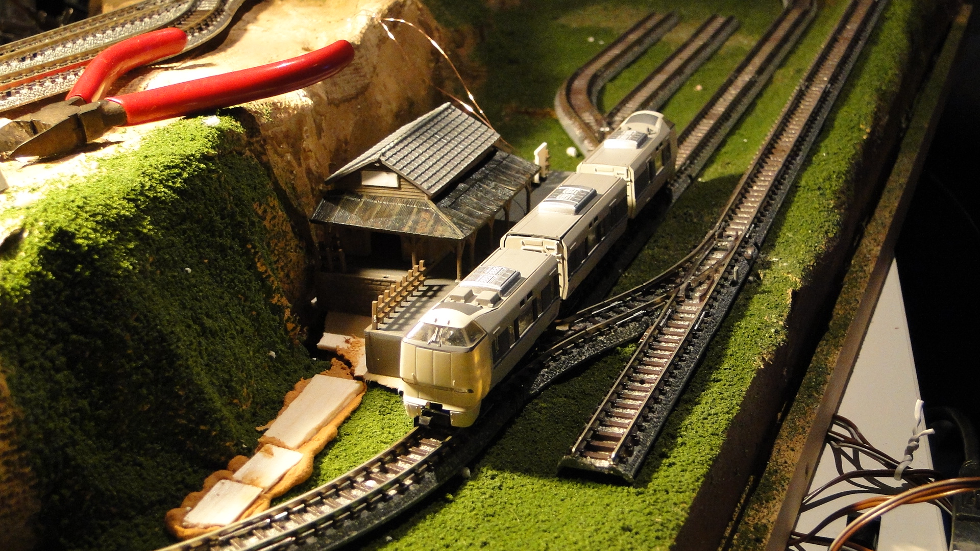
And then I mounted it into the station platform:
And then, it just worked!
What you can't see is the readout on the computer screen of the unique id on the button. This is what will allow me to perform actions (maybe sounds, path settings or signal settings) per each train I have with a button installed.
What's next? I might try some proximity detection; as you can see, I have a 2-road yard just to the right of the station which will be an engine shed and it'll require that trains don't smash through the rear wall ![]()
Tracking trains with an Arduino and RFID
So, you're now controlling your trains with your Wii Nunchuck and an Arduino... What if you get tired and want them to run by themselves? This next project will help you with one piece of the puzzle, as long as the trains are still moving :)
Whilst looking for the Wii Nunchuck Adapter at Toys Downunder, I came across RFID 'buttons' and an RFID reader that were compatible with the Arduino. Since I have the Arduino Mega, I knew I'd have pins/serial lines to spare, so I went ahead and added them to my order.
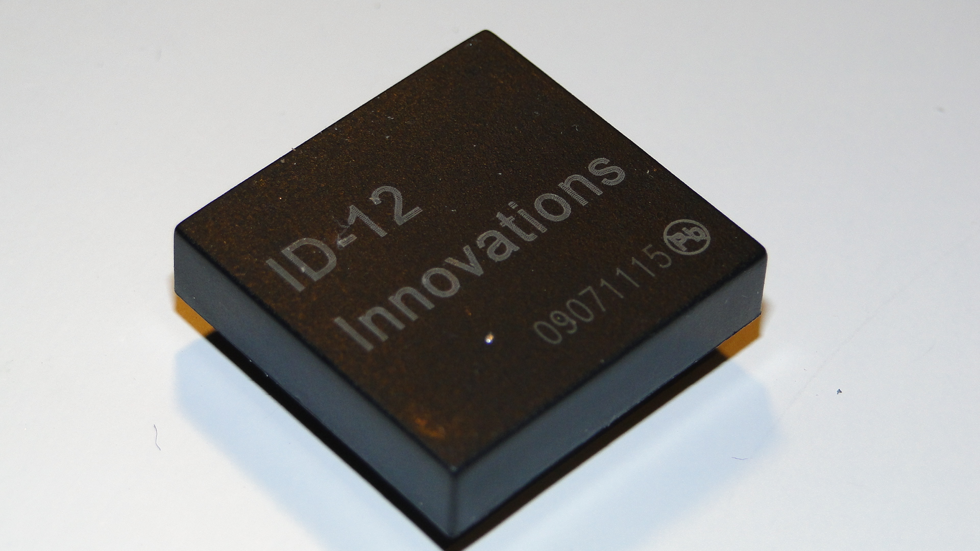
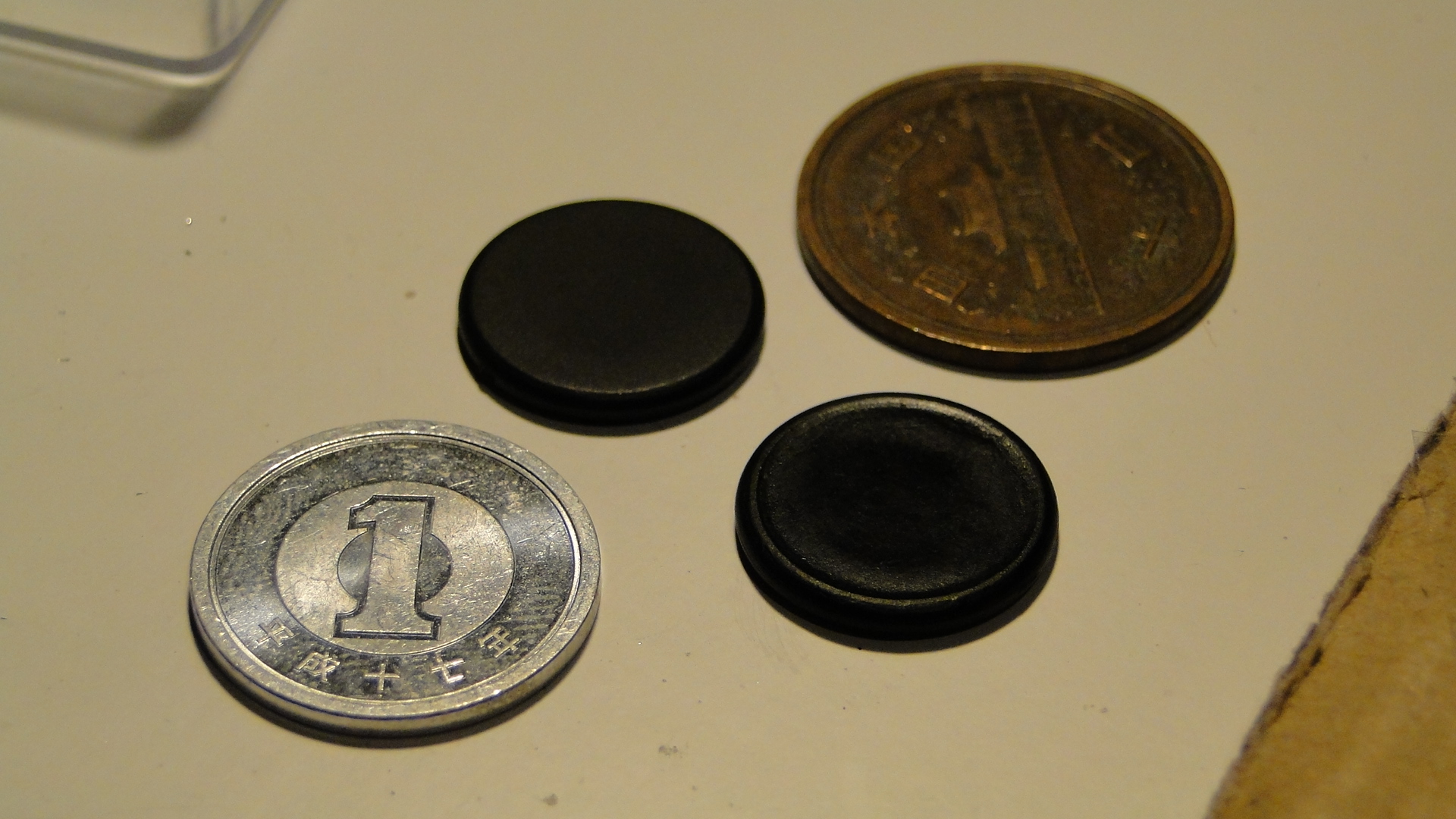
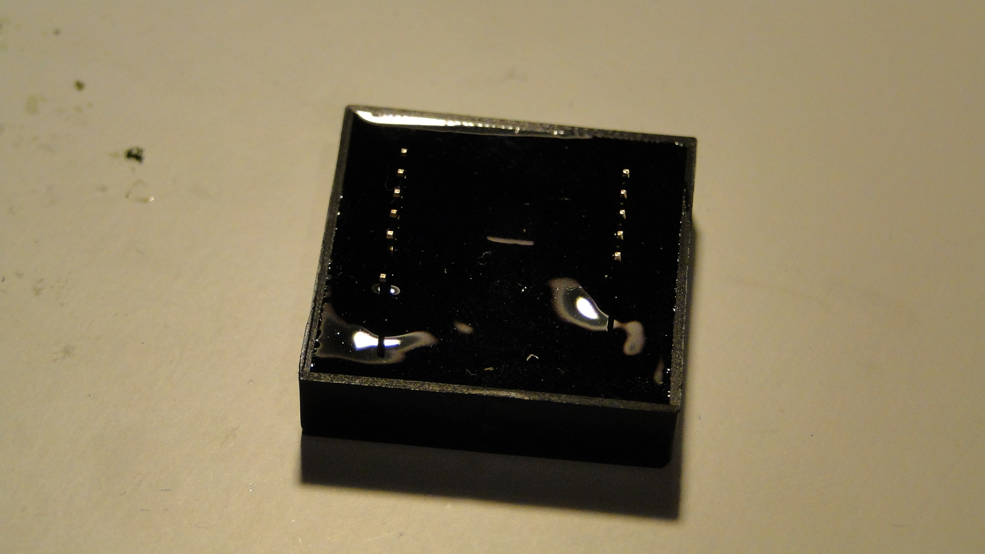
I bought the ID-12 RFID Reader and 2 RFID Buttons. I chose against purchasing the breakout board, as after reading the comments it didn't look like it would fit the ID-12 (only fitting the ID-20.) I've since asked Toys Downunder to correct this comment in case it really does, as soldering these readers is a pain. (Note, they have since updated the notes and the ID-12 does indeed fit. They also offered me a free one! I might act on that next time I go shopping there!)
Wiring up the reader was going to be pretty simple. I'd see examples of it wired here for a door lock and in the datasheet. I was a little confused as to which 'output' to use; there are two provided and I guessed right the first time (pin 9: Inverted TTL Data.) This output was fed into an RX port on one of the 3 surplus Serial ports on the Arduino Mega (Serial1).
After a quick bit of coding, I had the RFID reader picking up the RFID button reliably. You can find instructions on this from the Arduino site for another type of reader, but below is a quick code listing for getting it to work on the Arduino Mega. I wrote this with guidance from the previous door lock link and the Arduino site as well.
bool newData = false;
int cardData[16];
int idx=0;
void setup() {
  Serial.begin(9600);  // Hardware serial for Monitor 9600bps
  Serial.println("Starting Reader..."); //show some activity
  Serial1.begin(9600); //ID-12 uses 9600!
}
void loop() {
  while (Serial1.available() > 0) {
    cardData[idx] = Serial1.read();
    idx++;
    if (idx == 16) {
      newData = true;
      idx = 0;
    }
  }
  if (newData){
    newData = false;
    Serial.print("Found RFID device: ");
    for (int i = 0; i < 16; i++) Serial.print(cardData[i]);
    Serial.println(".");
  }
}
I've since read that external antennas can be hooked up, but creating one of these seems to be quite involved. Even though this ID-12 was the smallest reader available on Toys Downunder, there (after reading the datasheet) seems to be a slightly smaller one. It happens to be smaller since it doesn't include an internal antenna. Either way, if you choose to make your own, you may well be able to lay it in the trackbed. Otherwise, you can just shove a reader like this ID-12 into a trackside building or at the back of a engine shed to know which loco has arrived.
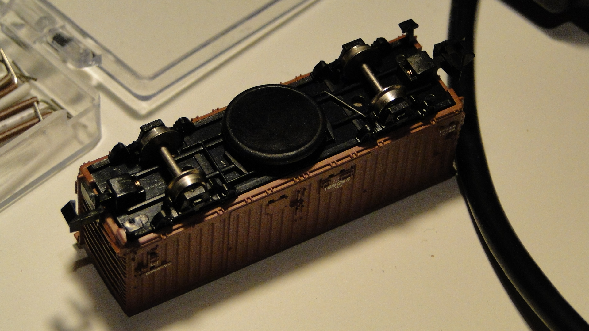
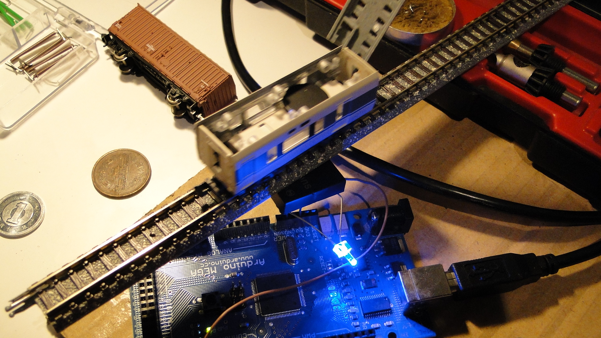
Initial testing showed that the Buttons could be read through my Thunderbird B-Train Shorty with motorised chassis; although the chassis wasn't powered at the time. I'll show the reader installed on a model railway in a future article.
Wii Nunchuck + Arduino Mega + Model Railway = Fun
Well, it had to happen... I bought the header/adapter from here and then, after a little rewiring to fit the Arduino Mega, got the Wii Nunchuck reporting data to my Arduino. Note that this has been done already in multiple places:
- Motor shield and model train!
- Wii Nunchuk Controlled Model Train
- Dawson Station: Wii Nunchuck Train Control?
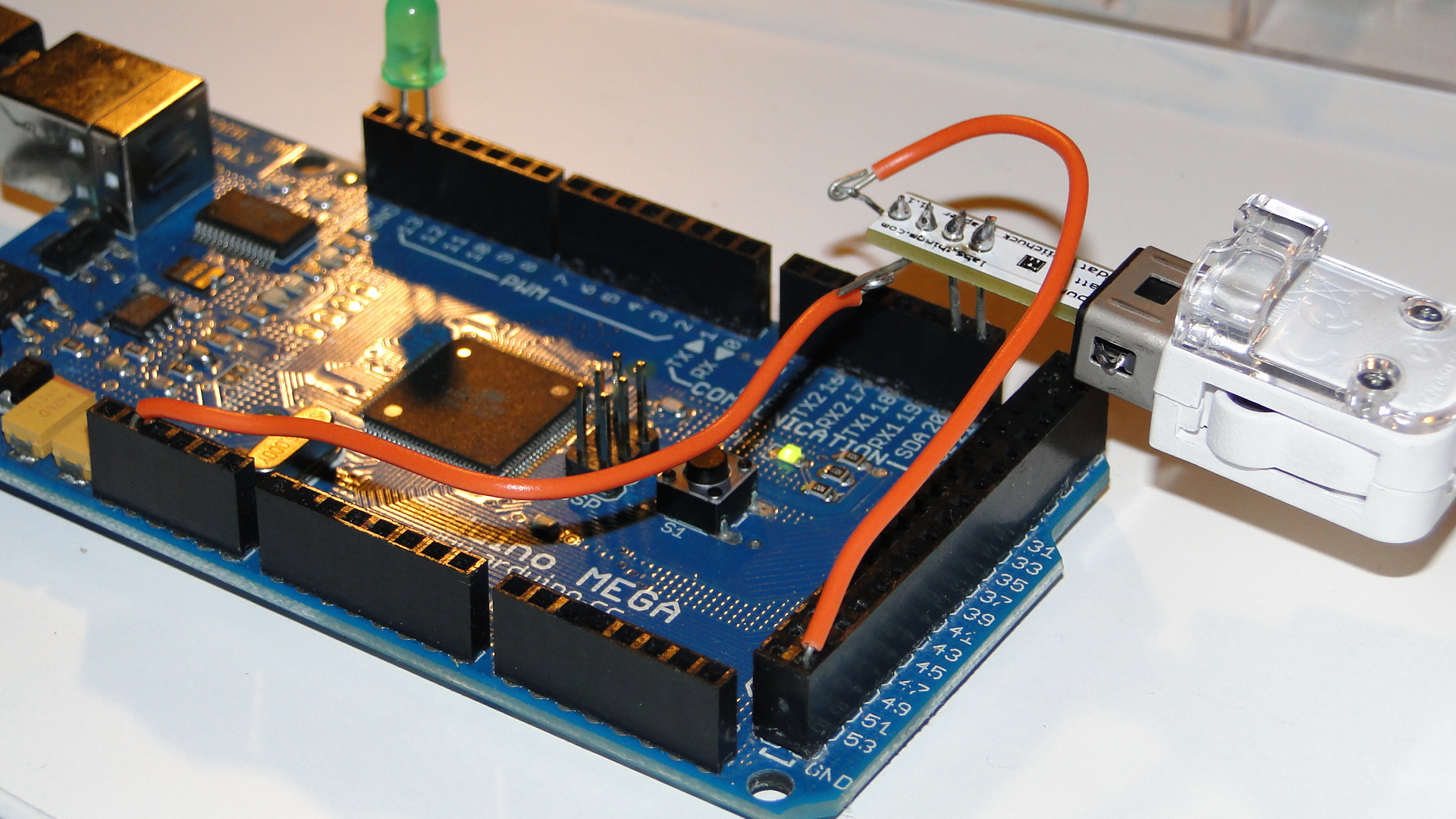
If you have an Arduino Mega, then make sure you have the Negative pin to GND, the Positive to 3.3v, the "d"/"data" pin to SDA20 and the "c"/"clock" pin to SCL 21.
You can then use this code to get the little train moving:
#include <Wire.h>
#include "nunchuck_funcs.h"
#define PWM_INPUT_PIN_1         2
#define PWM_INPUT_PIN_2         3
#define PWM_ENABLE_PIN_1        7
int throttle = 0;
int loop_cnt=0;
void setup() {
  Serial.begin(19200);
  nunchuck_setpowerpins();
  nunchuck_init(); // send the initilization handshake
}
void loop() {
  if( loop_cnt > 100 ) { // every 100 msecs get new data
    loop_cnt = 0;
    nunchuck_get_data();
  }
  loop_cnt++;
  throttle = nunchuck_joyx() - 127;
  if (throttle < 10 && throttle > -10) throttle = 0;
  UpdateTrackPower();
}
void UpdateTrackPower() {
  if (throttle == 0) {
    digitalWrite(PWM_INPUT_PIN_1, LOW);
    digitalWrite(PWM_INPUT_PIN_2, LOW);
  } else {
    if (throttle > 0) {
      digitalWrite(PWM_INPUT_PIN_1, HIGH);
      digitalWrite(PWM_INPUT_PIN_2, LOW);
    } else if (throttle < 0) {
      digitalWrite(PWM_INPUT_PIN_1, LOW);
      digitalWrite(PWM_INPUT_PIN_2, HIGH);
    }
  }
  analogWrite(PWM_ENABLE_PIN_1, abs(throttle));
}
Note that you need to have the L298 Motor controller from the previous post connected to get power to tracks!
Now I just need to think of a cool way to use the buttons on this controller. Currently I just have the top joystick controlling the train on the X axis with center being stopped.
Controlling your trains with an Arduino
A quick introduction to the Arduino
Arduino is an open-source electronics prototyping platform based on flexible, easy-to-use hardware and software. It's intended for artists, designers, hobbyists, and anyone interested in creating interactive objects or environments.
Arduino can sense the environment by receiving input from a variety of sensors and can affect its surroundings by controlling lights, motors, and other actuators. The microcontroller on the board is programmed using the Arduino programming language (based on Wiring) and the Arduino development environment (based on Processing). Arduino projects can be stand-alone or they can communicate with software on running on a computer (e.g. Flash, Processing, MaxMSP).
The boards can be built by hand or purchased preassembled; the software can be downloaded for free. The hardware reference designs (CAD files) are available under an open-source license, you are free to adapt them to your needs
Using it on your Model Railway
So, I recently purchased an Arduino Mega Microcontroller with the intent to control a Model Railway. This article will be the first in a series to show you how to use an Arduino to control different areas of a layout. Our first goal will be to create a controller/throttle with very basic Acceleration/Braking and a 12v DC Pulse Width Modulated output.
Note that this will all be based on DC electronics; this has nothing to do with DCC.
First, here's a list of web resources for controlling a 12v output with the Arduino:
- Basic 12v Output
- AdaFruit Motor Shield - Circuit that plugs directly onto your Arduino and provides outputs
- DIY H-Bridge Add-on
- DC Motor Control Using an H-Bridge and a PIC
- DC Motor Control Using an H-Bridge - Similar to above
- Dual Motor Driver with Arduino using a SN754410NE Quad Half H-Bridge
- L298 Hbridge meets Arduino mega
- PWM with l293/l298 - Provides great information on how to control a H-Bridge
- Controlling a DC motor with the Arduino and L293D
- DC Motor Driver v1.1
- 4A H bridge motor driver using the L298 IC
- Bi-directional Control Of Motors And The H-Bridge
- Others
What I created
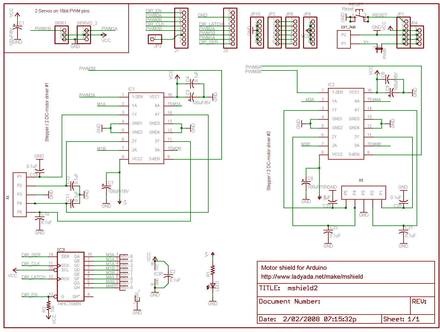
In the end I chose to use the schematics and information from the guys at pyroelectro.com which uses the L298 H-Bridge integrated circuit. My main reasoning was that, although they used a PIC microcontroller, they correctly controlled the L298 with PWM on it's input rather than it's enabling pin. Either way, the PWM signal is still created...
Here's the schematic. I've added a few extra buttons and LEDs and also added a potentiometer for speed control.
Notes:
- The IC is facing towards the viewer (i.e. so that the text on the IC is visible.)
- It's also recommended to use a heatsink!
- Ensure that you connect the ground(GND) on the L298.. It'll overheat and fry if you don't.
- You must use Ultra Fast Diodes for the flyback diodes. More information here
Right, what do you need to know?... The PWM pins are labelled on your Arduino board. By default they output a PWM signal when you feed an analogWrite(pin_number) to them. This creates a pulse that the H-Bridge will respond to. The frequency of this pulse (wave) will then govern the final output voltage to the tracks.
For direction control you either apply digitalWrite(HIGH) to PWM2 and digitalWrite(LOW) to PWM3 or vice versa for the opposite direction. Applying LOW to both pins will stop the output and HIGH to both will short circuit!
I've added S1 and S2 to control my direction. It starts off going 'forward', but pressing S2 will set the direction to backwards. The code is written to gradually stop and then accelerate in the opposite direction. Pressing S1 will then set the direction forwards again and the reverse will occur.
S3 is the emergency stop button. Resetting the throttle to zero will cancel the emergency stop flag.
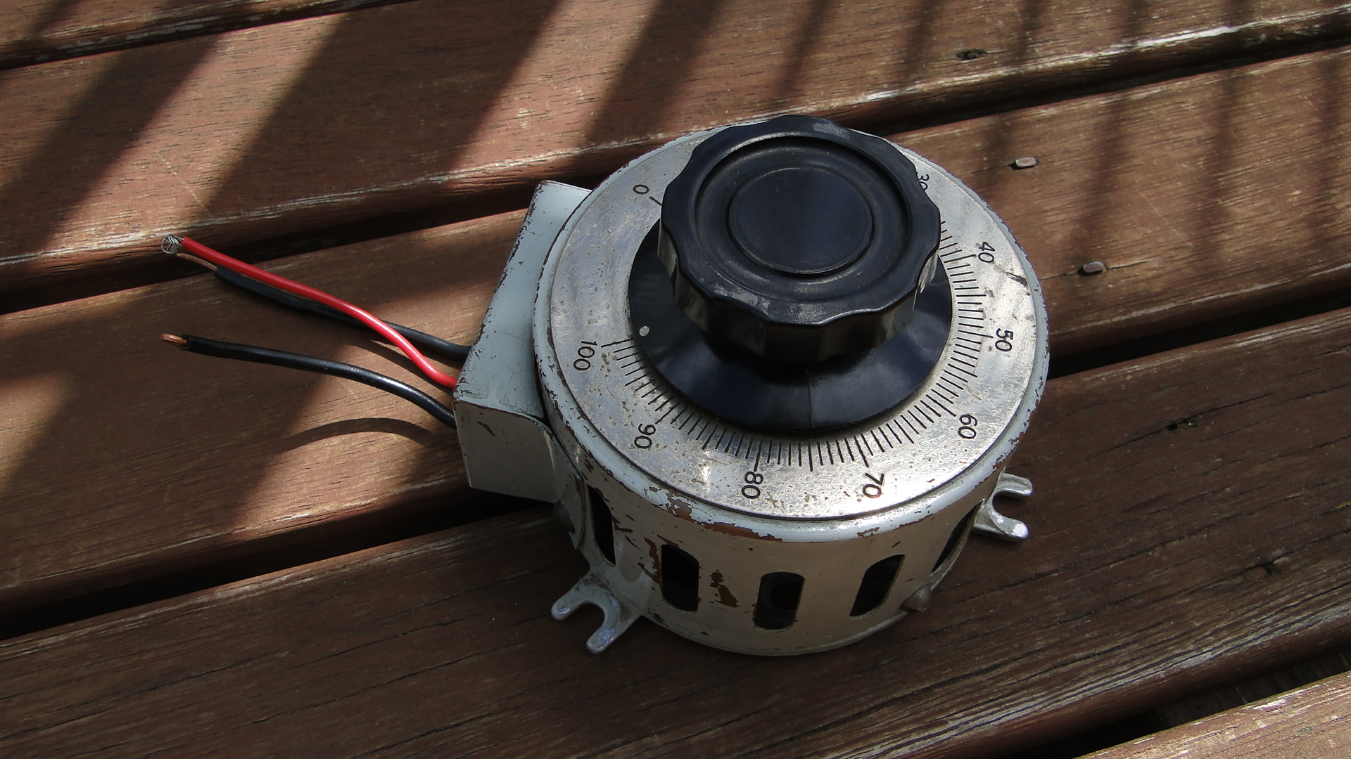
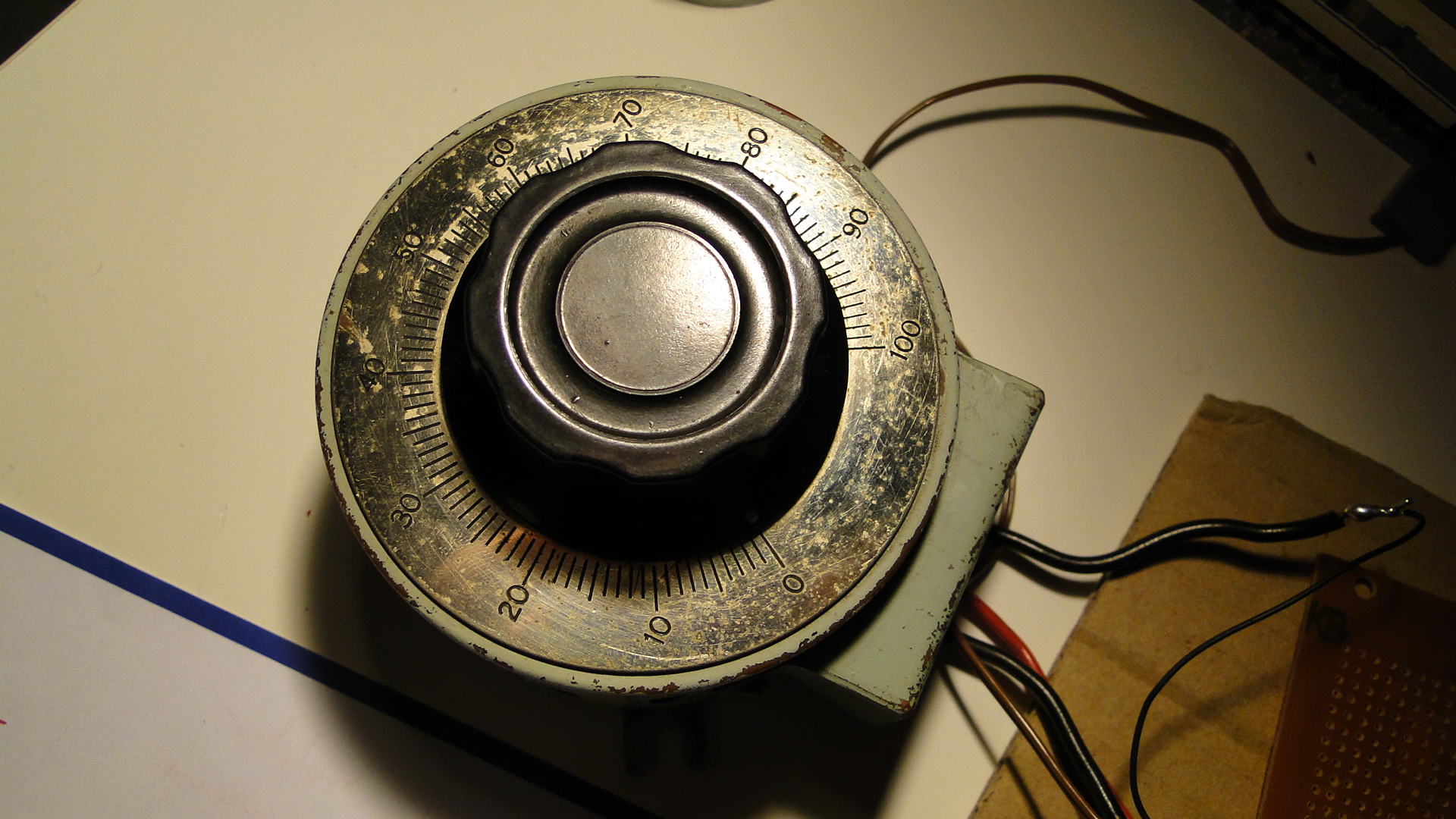
The potentiometer is the throttle... I found a huge one at an antique store down the road and love it. It's rated at 250ohm (no idea what current) and when at '100' the analogRead reports just over 1000. The throttle is only for speed, I really should add a brake lever, as when you return to zero speed the train will only gradually stop. You need to then hit the reverse (or emergency stop) button to stop the train faster.
You'll also require a 12v DC power supply. As your little engines may use up to 1A when starting, make sure this power supply is sufficient. Also, if you don't intend to have the Arduino plugged in to a computer after programming, then this 12v can also supply it (connect all ground wires together!). Just make sure it's a regulated and safe power supply. Note that different Arduinos can handle different voltages! Find your board listed here and then work out the power supply details, otherwise the Arduino Mega details are here (Input max 20v DC).
Source Code
The source code can be downloaded here.
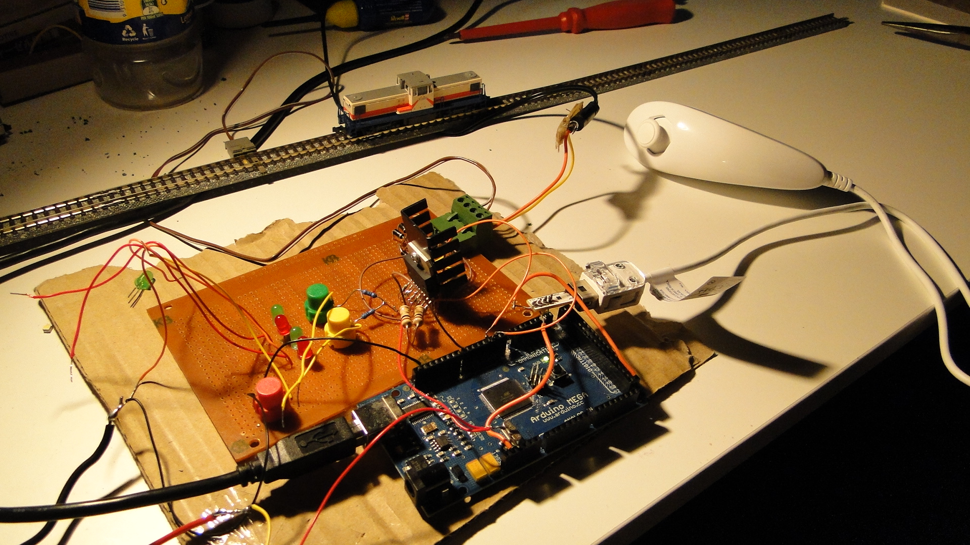
Photos
Here's a few shots of the current set up:
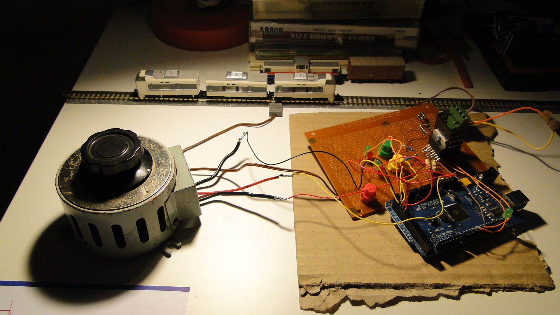
Please do ask any questions you have about this... I've probably skimmed over a lot and am more than happy to update this as necessary. I intend on getting on to more interesting things with this controller as I get the time.
Random Photos
Search
Tags
Links - Click for details
- Abandoned Rails (Japan)
- AIRLINE (Shinkansen Photography)
- Akihabara Station
- annexpressのブログ
- Australian Model Railway Magazine
- DCC普及協会ホームページ (Japanese DCC)
- Dead Section (Japanese Track Diagrams)
- Delicious Things (Japanese N Scale DCC)
- Densha Wotorou
- Digital Direct for Windows (DCC Server)
- Don's Dream World – AMAZING N Scale Japanese Layout
- Hatena::Diary
- Japanese N-Scale Modeling Forum
- JR Chiisai
- Kaz-T's blog レインボーライン (Rainbow Line)
- LED Resitance Calculator
- Masioka
- Poppondetta Blog
- RailFan Magazine, Japan
- Railmind
- Railway Travelers' Room
- Serenity Valley
- Shashinka Ichiban
- Shuzuku
- Sumida Crossing
- The next station is…
- Tomix N Gauge Track and Japanese N Gauge Trains
- TT Forums (Transport Tycoon Deluxe)
- 名鉄尾西線の貨物列車 (Nagoya: Meitetsu Freight)
- 日本型Nゲージ DCC改造例のご紹介 (Okiraku DCC)
- 泰 茅 轍 道 (Taichi Railway)
- 箱庭登山鉄道製作記 (Hakone-Tozan Layout Blog)
Archive
- July 2026
- May 2026
- April 2026
- March 2026
- February 2026
- January 2026
- November 2025
- October 2025
- September 2025
- August 2025
- July 2025
- June 2025
- February 2025
- January 2025
- November 2024
- September 2024
- August 2024
- July 2024
- June 2024
- May 2024
- April 2024
- March 2024
- February 2024
- December 2023
- October 2023
- September 2023
- August 2023
- July 2023
- June 2023
- May 2023
- April 2023
- March 2023
- December 2022
- November 2022
- October 2022
- April 2022
- March 2022
- February 2022
- January 2022
- December 2021
- November 2021
- September 2021
- August 2021
- July 2021
- May 2021
- March 2021
- February 2021
- January 2021
- October 2020
- September 2020
- August 2020
- July 2020
- June 2020
- May 2020
- April 2020
- March 2020
- January 2020
- December 2019
- November 2019
- October 2019
- September 2019
- August 2019
- July 2019
- June 2019
- April 2019
- March 2019
- February 2019
- January 2019
- December 2018
- November 2018
- October 2018
- September 2018
- August 2018
- July 2018
- June 2018
- May 2018
- April 2018
- March 2018
- January 2018
- December 2017
- November 2017
- October 2017
- September 2017
- August 2017
- July 2017
- June 2017
- May 2017
- March 2017
- February 2017
- January 2017
- December 2016
- November 2016
- October 2016
- September 2016
- August 2016
- July 2016
- June 2016
- May 2016
- February 2016
- November 2015
- October 2015
- September 2015
- August 2015
- July 2015
- June 2015
- May 2015
- April 2015
- March 2015
- February 2015
- January 2015
- December 2014
- November 2014
- August 2014
- July 2014
- May 2014
- April 2014
- March 2014
- December 2013
- November 2013
- October 2013
- June 2013
- August 2012
- April 2012
- March 2012
- February 2012
- November 2011
- October 2011
- September 2011
- July 2011
- June 2011
- May 2011
- April 2011
- March 2011
- February 2011
- January 2011
- December 2010
- November 2010
- October 2010
- September 2010
- August 2010
- June 2010
- May 2010
- April 2010
- March 2010
- February 2010
- January 2010
- December 2009
- November 2009
- October 2009
- August 2009
- January 2009
- December 2008
- November 2008
- October 2008
- September 2008
- July 2008