


 Melbourne BG SCS Train Timetable


Donnybrook (Pub), Victoria
Since around November last year, I've been choosing to enjoy Saturday lunch times at Donnybrook Pub, adjacent to Donnybrook Station in Donnybrook Victoria. It the first diesel-only V/Line station on the main-south (main-north?) line out of Melbourne. The station is only served by V/Line broad gauge, having the standard gauge pass by without any platform connectivity.
From the platforms, you have a great view in both directions... as well as the smoking garden at the pub.
Both directions are very easy to frame, north (southbound) from the platform and south (northbound) from inside the fence at the level crossing. Let's start with the standard services which will (usually) pass through on a 2025/2026 Saturday morning.
7MS1 - Aurizon Melbourne-Sydney Container
This train is due through Donnybrook at 11:15, but it's usually early. For 2 weekends in a row, the same ACD6057 loco was on point...
The next 2 weekends, it was ACD6073 instead.
Finally, something different... but not. CM3316 in the lead, two weekends in a row.
7MS2 - Pacific National Melbourne-Sydney Container
This service is due through at 13:30 and would only be seen if I chose to stay past the 1:04pm Southern Cross Service.
5BM9 - SCT Brisbane-Melbourne Freight
This service is due through Donnybrook at 07:40am and I've never seen it less than 4 hours late!. It's meant to stop in the loop north of the station for 15 minutes to pass a V/Line service, but it doesn't seem that the V/Los have ever had to worry. Either way, I'm not complaining as getting to Donnybrook before 8am would be hideous.
And then from the level crossing, looking north...
7MC2 - Pacific National Melbourne-Griffith Container
This one is much later in the arvo, passing Donnybrook around 15:30. Actually, it seems to have been scrapped from the most recent timetable revision... but is still running?
Unscheduled Services
Both run by SSR, and well, one is scheduled and one is not. First, the ad-hoc movement of two bulldogs:
And second, an xCMx grain train, which I've only seen come through once!
V/Line Passenger Services
From the little ones, known as Sprinters, which are now becoming very rare! I think Seymour is now the last proper-V/Line service (Metro uses them down south) where Sprinters are still scheduled.
They get lashed up anywhere from 2 to 5 in a row. 2 is the minimum so as to confirm proper axle counting at level crossings.
And then you have the V/Locities. They come in "three" styles... old with narrow windscreens on broad-gauge...
New with wide windscreens on broad-gauge...
And finally, the same wide-screen on standard-gauge...
Kilmore-East Broad Gauge Quarry Service
And then there's sometimes a random BG gravel service... but I haven't caught it at Donnybrook yet... so here it is at Jacana...
That track don't look too safe!
Getting A Locally Debugged Logic App’s Callback URL
For those of you who want to locally automate testing of Logic Apps running in VSCode, this post is for you! Across the web, there are people asking for a dynamic way to get the Callback URLs for locally debugged logic apps. They run via func.exe and it has been previously thought that the only place to get the URL with the required 'auth' signature was the overview window of the workflow:
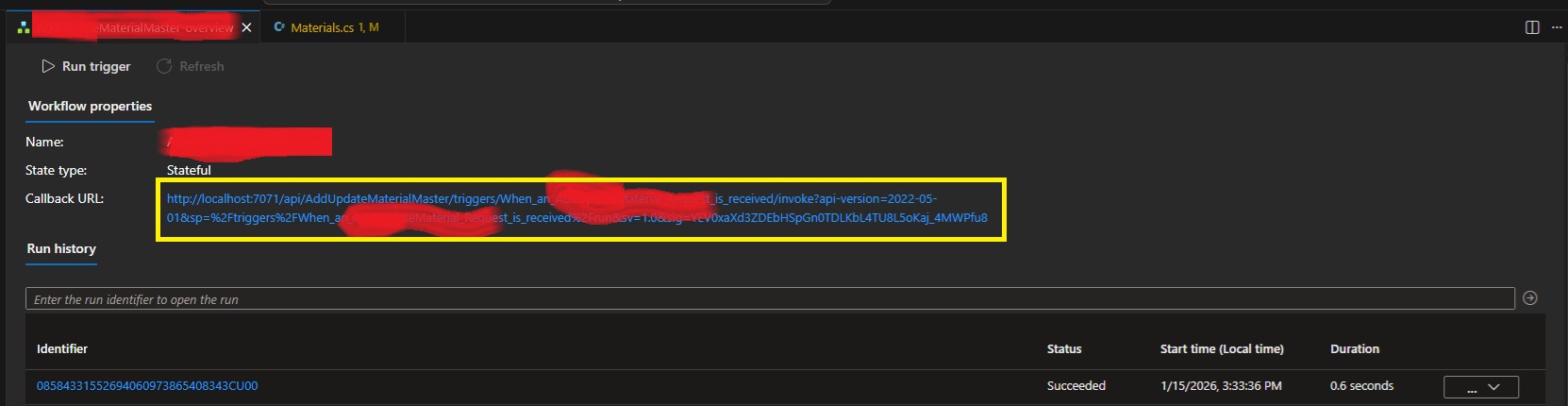
Fear not! I've used the development tools to rip apart VSCode and have worked out that our trusty local func.exe exposes all the webservices that Azure does! The full list of services available is over here. Specifically endpoints to list workflows, workflow triggers and then trigger Callback URLs with full signatures!
internal class LogicAppDetector
{
    private string base_url;
    public LogicAppDetector(string baseUrl = "http://localhost:7071/") {
        this.base_url = baseUrl;
    }

    public List<LogicAppWorkflow> GetListOfWorkflows()
    {
        var workflowListJson = WebClient.DownloadAsString(base_url +
            "runtime/webhooks/workflow/api/management/workflows");
        return JsonSerializer.Deserialize<List<LogicAppWorkflow>>(workflowListJson);
    }

    public List<LogicAppWorkflowTrigger> GetWorkflowTriggers(string workflowName) {
        var triggerListJson = WebClient.DownloadAsString(
            base_url + "runtime/webhooks/workflow/api/management/" +
            "workflows/" + workflowName + "/triggers");
        return JsonSerializer.Deserialize<LogicAppWorkflowTriggerContainer>(triggerListJson).value;
    }

    public string GetWorkflowCallbackUrl(string logicAppWorkflowName)
    {
        var wf = GetListOfWorkflows().FirstOrDefault(x => x.name == logicAppWorkflowName);
        if (wf == null) {
            throw new Exception(
                "Couldn't find workflow [" + logicAppWorkflowName + "] in the list?");
        }
        var trigs = GetWorkflowTriggers(logicAppWorkflowName);
        if (trigs == null) {
            throw new Exception(
                "Couldn't find triggers for workflow [" + logicAppWorkflowName + "]?");
        }
        if (trigs.Count() != 1) {
            throw new Exception(
                "Incorrect trigger count for workflow [" + logicAppWorkflowName + "]" +
                " ... count was " + trigs.Count() + "?");
        }
        var callbackUrlJson = WebClient.PostJsonData(
            base_url + "runtime/webhooks/workflow/api/management/workflows/" +
            logicAppWorkflowName + "/triggers/" + trigs[0].name +
            "/listCallbackUrl", null); //payload is actually NULL.
        var callbackData =
            JsonSerializer.Deserialize<LogicAppWorkflowTriggerCallbackUrl>(callbackUrlJson);
        return callbackData.value;
    }
}

internal class LogicAppWorkflow
{
    public string name { get; set; }
    public string definition_href { get; set; }
    public string href { get; set; }
    public string kind { get; set; }
    public object triggers { get; set; }
    public bool isDisabled { get; set; }
}

internal class LogicAppWorkflowTriggerContainer
{
    public List<LogicAppWorkflowTrigger> value { get; set; }
}

internal class LogicAppWorkflowTrigger
{
    public string id { get; set; }
    public string name { get; set; }
    public string type { get; set; }
}

internal class LogicAppWorkflowTriggerQueries
{
    [JsonProperty("api-version")]
    public string apiversion { get; set; }
    public string sp { get; set; }
    public string sv { get; set; }
    public string sig { get; set; }
}

internal class LogicAppWorkflowTriggerCallbackUrl
{
    public string value { get; set; }
    public string method { get; set; }
    public string basePath { get; set; }
    public LogicAppWorkflowTriggerQueries queries { get; set; }
}
You'll just need to plug in whatever you're using for Web Requests to GET and POST. Also make sure that the actual Logic App is running/debugging in VSCode!
Leave a comment if you have any issues.
ATX12VO – MSI MPG Trident AS
So this rabbit hole got very deep, very quickly! Bought a new machine... a smaller form-factor unit with great asthetics! Little did I think about any upgrade paths.
It came with an 8gb 4060 Ti which has been flawless for my needs, but I'm thinking I need 16gb... so... as that it's got enough room inside for a better video card? Why not?
I chose an RTX 5070 Ti based on price and RAM. As I was buying the card, the cashier told me I'd need 750+ watts of power and tried to sell me a new supply on-the-spot. Instead, I decided that I'd get home and check what was in the tin first, as brief googlin' indicated that some Tridents came with a Gold Power Supply.
But nope... my MSI Trident contained a 500w SFX. So, I went back to another PC store that afternoon and bought a Cooler Master V850 SFX Gold. A nice amount of power for my card!
Unfortunately, no amount of cable-jiggery-pokery would get the new ATX motherboard power cable to connect to the motherboard power socket? What gives? It turns out the Trident uses an ATX12VO power supply! A short-lived game-over ATX standard that Intel tried to push. They failed so-much-so that the standard has already been forgotten about. I take it I didn't realise how old this PC already was when I bought it. It was a refurb, so it probably lived its life in a gaming cafe.
Trying to find an exact ATX12VO SFX PSU with the correct wattage turned out to be futile. They just don't make them anymore! I started considering re-wiring the old plug from the old supply onto the new PSU, but there's a single pin that doesn't match: +12VSB. This wire is a constant 12v from the power supply to the motherboard for ancillary services. Things like charging USB devices when the machine is off (which could actually cause a lot of current draw?) and the power switch... which, thanks to ATX soft-power, needs a constant current trickle to determine if you've pressed it! I could possibly buck-convert the DC, like other people have tried... there's even a project for it here.
The googl' rabbit-hole went deeper and intially I found that Corsair has a custom cable, but I'd already purchased a Cooler Master! I then stumbled across Moddiy's site where they mention Cooler Master and ATX12VO on the same page! They'll create the custom cable for you with inline 12v boost for VSB!
In that last shot it looks like a snake processing a big meal, thanks to the heat sheath.
Cooler Master V850 SFX Pinout
The cable came with no mention of which end was for the PSU. Both ends have the same "ATX plug shape", so I didn't want to plug the damn thing in backwards. IF I had attempted to plug it in, I would've realised that only one side will go into the motherboard, but I was averse to doing it that way.
Instead, I started reversing both ends of both the power-supply-included cable and the new Moddiy cable to work out what was what. Turns out I really only needed to reverse the Cooler Master original cable on the plug, not the socket.
So, looking at the above cable, as it's shown, you get the following pinout:
| 10P M/B cable (not socket), looking at the plug with the notch facing up... | ||||
|---|---|---|---|---|
| 12v | 12v | -12v | +5vsb | POWER_OK |
| GND | GND | GND | 12v | 5v |
And that means the end of the cable with the 'top-central' pin missing is the Power-Supply side. The end with the 'loop' wire is the motherboard side. Everything routed through to the other end, as expected to match the ATX12VO standard.
Of course, the +5VSB didn't, as it goes through the inline DC converter which prevents a continuity test.
Mounting It In The Case
After taking the side panel off the machine, you'll find that the existing power supply has a mains lead running from the rear of the case to it's mounting bracket at the front.
First up you'll want to remove the 4 screws under the machine to release the mounting bracket.
Next, you want to gently push the power supply and bracket up, compressing the cluster of cables above to clear the bottom edge of the case.
Make sure to move any WiFi antennae out of the way! Once clear, the power supply can be lifted out via the base, disconnecting all cables (2 motherboard and 1 PCIE) at the same time.
From here, remove the base and attach it to the new power supply. Make sure that the notch is facing right when the power supply fan is facing you. This will allow the fan to line up correctly with the vent on the other side of the case.
Also make sure you switch the bloody thing on if it has an external switch like this one does! There'll be zero access to that once it's installed. Finally, connect the power cable and slide the new supply back into the case.
Line up all the WiFi antennae so you don't pinch them on installation! Route the required power cables to the expected sockets. I actually considered running the SATA power to the drives to take the pressure off the motherboard's voltage regulators... but maybe I'll do that later.
Power Test
With it all installed... I just sent it...
A healthy click from the relay inside the new power supply (that's a new feature!) and we're off!
Wooooooooooooooo hoooooooooooo.
New GFX
This is nearly Apple-level packaging. Very schmick!
They also totally overdid the protective film! I suppose they wanted to have ASMR vids from the streamers.
Installation is harmless... just watch out for sharp case edges! Oh, also, the new PCIE 5.1 Power Cable has a right-angle connector housing which is optional:
You can pry it off by getting a tiny screwdriver in those side clips. Anyway... the card was in... what to do?
WIN! Nvidia installed new GFX drivers automagically and it all JustWorked(TM)! A final test:
Perfect 4K 10000fps.
Dell PowerEdge 2200
This beast seems to have had a hard life and needed a bit of skewing to get it back into shape. I saw it on the usual auction site, from a seller nearby, and my offer was accepted! It seems nobody wanted it, as the seller had mentioned it was EISA and that standard ISA cards wouldn't work... little did they know!
The Dell PowerEdge 2200 contains a Dual Pentium II FX motherboard with EISA and PCI slots. Not much IO on the rear meant I could finally utilise one of the many USB cards sitting in the junk box! The case itself turned out to be not-quite plumb, so it received a few taps of love to get it as-square-as-possible.
I didn't wait to boot it up and, as expected (and mentioned by the seller), it came up fine. 256mb of RAM and a single CPU. It did keep throwing the following error though:
After replacing the CMOS battery and saving CMOS settings, I had assumed the error would have pissed-off, but it didn't? A quick google instructed me that this was the EISA bus reporting an error, which seems to be a secondary configuration requiring a boot-floppy configurator. You'll find the EXE (which writes a floppy for you) over here, even though it mentions that it is for a 2100.
How cute is that? Dell still has support for this machine! Either way, the configuration was saved, as there was no EISA to configure, and the error went away!
More CPU
The machine only had one 333mhz CPU installed, with a terminator in the second slot.
I google'd, checking what CPU speeds were available in the Deschutes Pentium II line and managed to procure two 450mhz units. Of course, I should've done proper research as it turns out that the motherboard's FX chipset's 66mhz bus meant it peaked at 333mhz. Hence why the existing CPU was only 333mhz. Even funnier, the jumpers on the motherboard only indicate 233mhz and 266mhz settings?
Turns out that RSVD1 = 300mhz and RSVD2 = 333mhz! The already-purchased 450mhz CPUs went in after grafting over a heatsink from the existing 333mhz CPU. I must admit, too much effort was required to remove the old heatsink!
I had to actually go and buy a solid new torx driver. I only attempted this after finding that this is the internet and people have already struggled... and triumphed! I actually had to hammer the screwdriver into the screws to be able to turn them without stripping the heads.
The CPUs were individually tested and then installed, happily underclocked. Of course, this was short-lived when the BIOS reported the following issue:
I needed a second CPU thermostat!... so I tried to work out how the existing one worked. It happened to be a directly-wired AD22103K, of which are mildly unobtanium. I went full-dodge and ordered it with a few EPROMs from China.
I wired it up as per the other themister and, well, the BIOS stopped complaining!?
More RAM
The Retro Web's page on the 2200 specifies EDO SDRAM and so I hunted down the box'o'junk. Of course... I had nothing that looked like the existing DIMM:
Lots of RAM was found, but the middle slot didn't seem to align?
I wonder what that middle slot specifies. Either way, I managed to find 3 more 64mb sticks...
Which then totalled 457772mb!
Nice. That means we're 256 + 64 + 64 + 64 (aka 512 - 64)... which is great as Win98 hates 512 and above.
Filling the EISA slots
There ain't much available for EISA slots on the marketplaces. I managed to hunt down a 10/100 Ethernet card, to free a PCI slot...
And then a second SCSI card, to provide an external SCSI port...
They all installed cleanly, with the SCSI card taking up the entire depth of the case! I think that's the first time I've ever used the plastic supports on the right of any AT/ATX case. You'll need the EISA configuration disk and then any relevant configuration files. The SCSI card worked from the configs already on-disk, but the ethernet needed a download.
One note for the SCSI card was that I needed to set it from Standard Mode to Enhanced Mode via the EISA Configuration Disk. I spent a lot of time trying to find DOS drivers for the card, until I realised that EISA is 'all powerful' and all settings are done via CFG files and the system-in-question's EISA configurator!
Windows 98 SE
Everything just worked! Quite amazing, really. The SCSI card needed a "find non-PNP hardware", as it was installed after Windows and is not PNP, despite being EISA.
Of course, Windows 98 doesn't use the second CPU, so mildly useless! It's bloody quick though... it takes more time to count RAM than it then does to get to the network login prompt.
Windows 2000 and XP
Win2K hates EISA! I suppose I could install a PCI network card just for it, but that'd sorta ruin the experience. Same goes for XP... but they do run well!
BeOS 5.0
Installed and worked perfectly.
The teapot spun and the CPU graphs danced!
Redhat 6.2
The HP J2577A 100VG EISA Ethernet card didn't work straight away, but this article at HPE's support forum indicated that I needed to insmod hp100, and?...
Yey! Adding the alias to /etc/conf.modules didn't quite get it loaded on boot... so I used linuxconf and then client -> local settings to get the adapter enabled and set up.
Next up I followed the instructions over here to get OpenTTD 0.1.4 going. Same problems and fixes as per that article and ....
Lol... what is that? I hadn't even realised I was running in 8bpp! How to fix? Xf86 runs in 8-bit by default, so... run as test of startx with...
#startx −− −bpp 16
And?
Yup! Looks good... you can commit this to /etc/X11/XF86Config with:
DefaultColorDepth 16
... in your "Screen" section. It's not DefaultDepth, as that's an alias in newer Xorgs, etc. Enjoy!
California, USA – December, 2025
This was a work trip to the USA for a software release. 13 days were spent in the greater LA area, with most of that being locked-down in an office, getting software deployed, integrations piped and data flowing. When this wasn't happening, it was already dark'o'clock thanks to USA being in Winter and the sun setting around 4pm. Either way, I still managed to see a few trains and flea markets... even for a work trip!
San Clemente
Pronounced San Cle-me-nie, San Clemente is a cute little beach town is just south of the greater LA area. The southbound rail to San Diego runs right along the coast past a few restaurants with great train-watching capability. I made the team choose the San Clemente Pier a few times for dinner so I could see what was passing.
During the day you'll get Amtrak and Metrolink push-pull (both cab-control and actual double-ended-loco) sets stopping erratically or passing at speed. I do note that Amtrak only stops at the Pier and Metrolink only stops at San Clemente Station, so do be careful if you're actually wanting to catch a train and not just seen them.
I had a night free during the week I was there and dawdled down to San Clemente Station. There happens to be a 7-Eleven combini nearby, but don't try this:
It was awful... and I knew it would be after seeing the crust still in the packet... I still tried it anyway! They also have ridiculously oversized cans of beer... no one was around, so I enjoyed one at the station.
Excuse the random photos as I was just using my phone at this point... no need to lug the real camera out when it's dark and impossible to get a good shot.
Metrolink came and went, and so did I. There's a southbound freighter that passes somewhere between 8pm and 9pm in winter time, but it took a few days to be able to see it. I'd watch the San Juan Capistrano Station railcam on the odd night to see if I could see a freighter passing... in the vain attempt to then run from the hotel (way up near the highway) downhill to the station to see it. I tried it once and could already hear the level crossing active with wagons passing when I was still too far away... so that approach was never going to work.
On one of the last nights, I just loitered until a bloody train came... it happened to be at around 915pm and was the usual BNSF jumble of autorack and tanker/mixed.
I'd also caught a northbound amtrak on another night. Excuse the quality, but you can also see the double-ended locos here:
And actually, that last video above was taken after a random walk along the track beside the railway line from San Clemente towards the Pier. It's actually quite nice with ample level crossings to give you enough advance warning!
A final note about the Pier was that there's mutliple copies of this painting... and I love that it includes a ballast wagon? I assume the train was parked there during the work to rectify landslides?
San Juan Capistrano Station
Work had finally concluded and it was time to enjoy friday+saturday+sunday in LA, staying in Hollywood!? I hadn't chosen the hotel+location, but wasn't complaining as Loews Highland Bvd looked to be a nice spot! I had to get there first though... and it wasn't easy thanks to the train schedule through San Clemente favouring southbound passengers in the AM and northbound in the PM! So? I caught a bus, tapping on with my CommBank Travel Card. How bloody convenient!
This took me into San Juan Capistrano and, well, I felt guilty that it was still 8am and I was there to transit. The town looks adorable, with a lot of old-fashioned shops to check out. Nothing was open and I wanted the next northbound train.
Of course, two south-bounders would pass before a north-bound arrived to take me.
Note that you need to buy Amtrak tickets online, or via a shitty little kiosk that's hard to find at the station. Ask the friendly volunteers for help to find it, as there are no Amtrak staff to be seen and their office (contained in old louvre wagons!) is shut.
I jumped on the next northbound heading for Los Angeles Union Station.
LAX - Los Angeles Union Station
Not to be confused with the airport, this station shares the same code! Not much to mention except lots of walking! There's one long underpass with branching entrances to each platform via stairs and ramps. If you want to transfer to metro or buses then get ready to run!
I took the subway to the hotel on Highland in Hollywood and then ventured north to visit a model railway shop.
The Train Shack
Santa Fe on the outside? What a mural! Love it. The Train Shack is pretty easy to get to by public transport... just take the subway to North Hollywood and then any bus heading east along Magnolia Blvd.
Inside it was a perfect throw-back to what model railway shops used to be like in Canberra. I still miss Hobby World in Civic! Anyway, here? Lots of Lionel and a great mix of everything else...
Even Japanese N Scale! I only took mild offense to the Kiraras being called "trams".
I bought a junk 4-4-0 Bachmann Old Timer Steam loco... for display, for now.
It can be a challenge sometime in the distant future. Meanwhile as I unboxed the train from its tattered housing...
Check out those ads!
El Monte
Although the shots of the loco above were at night, I actually went on a mini train trip after visiting the The Train Shack. I caught the bus east from the model shop to Burbank MetroLink Station and then caught the next south-bound to Union.
I then took the next San Bernadino east-bound to check out El Monte Station. This station shares trackage with Union Pacific and I really wanted to see a freighter operating. The trip out to El Monte is pretty cool as the track also runs parallel to a highway where you get to race traffic.
Of course... no freighters... but a nice pass at the station loop thanks to it being single track either side. From here I went back to Hollywood, ate and slept.
Vineland Swapmeet
Something USA does different: flea markets (aka Swap Meets). These are seemingly more-permanent, operating every day of the week! Vineland Swapmeet is out east in City Of Industry (Yes, that's the actual suburb name) and was easy-enough to get to.
I wanted to get there early, so I took an express highway-bus (which also runs parallel to the MetroLink line!) to El Monte Bus Interchange (not to be confused with the MetroLink station) and then a bus south along Valley Boulevard. It was then a 15 minute walk up Vineland Ave to the outdoor drive-in cinema that hosts the swapmeet.
At the gate, proceed to the left and down the side to the ticket booth. There were many people waiting in the middle of the main gate, which was open, but they seemed to be waiting to be called to be allowed to open/pay-for their stalls? I watched for a bit but realised customers were just entering down the side.
Final note before the barrage of photos: bring cash! I didn't... cash-only for entry! But they let me go inside and use the (mildly dodgy) ATM ... I risked it because there was no other option in the vicinity and I used a travel-money card which I could easily limit if anyone were to try hack.
There was a nice amount of everything. Half of it dollar-shop-shite... and then the other half being absolute junk! WHoooo!
Also note that the MetroLink line runs along the northern fence... so do take note of the timetable so you can also take terrible videos like this!
Of course, it wouldn't be until the final corner where I find a stall with everything I could ever want. I ended up buying a sealed pack of sony floppies and two trackball mices for the grand sum of USD$10.
Fullerton Station
This was a blast. I took the express bus back to Union Station and then the next Oceanside-bound MetroLink. Amtrak is a lot harder with seats and ticketing! There's a great cafe at Fullerton Station and they served up a delicious chicken burger meal! I then realised an unusual amount of train-buffs hanging around and, upon speaking to a few, realised that I'd turned up on the same day as their annual christmas get together!
The fog/smog was thick, and it wasn't long before a freighter added to the pollution...
Of course, when you're looking in one direction... you miss what's coming in the other direction!
The UP I had wanted to see the day prior showed up in the middle of this consist?
Is that Bill Clinton? I had seen enough trains... it was time to find another model railway shop.
Norwalk Station
I took the next westbound to Norwalk Station. It's on a great curve... that actually lead me to think that the freighters through Fullerton may have looked nicer here?
I waaaalked to the bus connection, quite a ways from the station as I'd just missed the bus that departs the actual station. The connections weren't the best on a Saturday.
Railmaster Hobbies
Down middle-south in Bellflower is Railmaster Hobbies. Not as big as The Train Shack, but still a beautiful shop! Lots of G Scale in all conditions!
I bought up some Santa Fe boxcars, resisting the urge to buy O Scale stuff that would not have fit in my suitcase!
Bellflower ain't an easy place to get to... but you really just need to wait for buses to show up. I was starting to doubt Google but managed to get there after waiting a while past the bus' expected arrival time.
Rose Bowl Flea Market
This was just one of those holy-moly-it's-on-the-same-weekend-as-my-visit! The Rose Bowl Flea Market has been going for 50 years and is on every-so-often as the Rose Bowl Stadium in Pasadena. After visiting the lower suburbs of LA, I was pleasantly surprised by the clean and tidiness of the northern suburbs.
Anyway, Metro was taken to Memorial Park Station and then the bus to the stadium. A very pleasant trip and I happened to be the only passenger on the bus? It seems LA is definitely a 'driving' city.
Not much to say but... it's huge! 50% vintage clothing... no dollar-shop shit... but also not much tech or model railways...
That stall in the final shot above had a total random selection of Lionel O and other G scale stuff... but nothing I wanted to lug around. It was great to go and check the place out!
You'll Never Find A More Wretched Hive Of Scum And Villainy
I made my way back to the hotel and realised I'd be 8 hours early to the airport if I left straight away. Instead I got off at the east end of Hollywood Bvd to check out something random. After Popeye's for lunch, it was across the road to the Scum And Villainy Cantina!
It's perfect and you should go and visit if you're on the dreadful strip!
Animaniacs
I nearly forgot something. During the first day of travelling to The Train Shack and then Burbank Station, something was faintly memorable about the name 'Burbank'... why did that ring a bell? I then remembered... Wakko Warner always used to mention it in Animaniacs with the WB studios being somewhere in 'Downtown Burbank California'? A quick google showed that it was due south of The Train Shack down North Hollywood Way! I'd gotten within a kilometre and hadn't visited.
I changed that mishap... I went back as I still had time... and I also went back to The Train Shack, because, why not... but the main reason to go was for this:
Haha... it's perfect. That's the Animaniacs house... right there in front of me!
See Ya, Los Angeles
There were other things that were hilarious. Scientology XMAS anyone? Goodwill stores with nothing but junk. The Nickelodeon HQ? That's a nostalgia hit as well... as with seeing a rugrat doll above at Rose Bowl.
Delivery robots? New fire-fighters being sworn in? Electric motorbikes?
Denny's? (Love that shit!) Hilarious Hyundai number plates? Cyber Trucks? Lots of Cyber Trucks!
A subway that ... well ... attracted the wrong people and had a constant thick unbreathable atmosphere of urine?
But that was it... I then loitered my way back to the hotel, got my luggage and took the FlyAway Bus from LAX...
Well, I nearly did. The bus I was scheduled on failed in front of us. The driver, as he opened the luggage door, had a bolt sheer clean from the chassis, causing the door arm to fail when he tried to close it. He forced it as-closed-as-above and actually made us board... with everyone expecting their luggage to end up on the highway. Forfunately, another bus came to save us before this could occur. Before long we were off.. on the highway... as there's no quick rail connection.
If you look closely at the middle building in the shot above, it turns out a building in the middle of downtown ran outta cash and the artists got involved! A great note to end a trip to LA on!
Buyee Have Lost The Plot (And It’s Sad)
So, as I usually do... I was obsessively buying random stuff on Buyee, ready to consolidate and ship to Australia.
| The Shopping Cart | ||
|---|---|---|
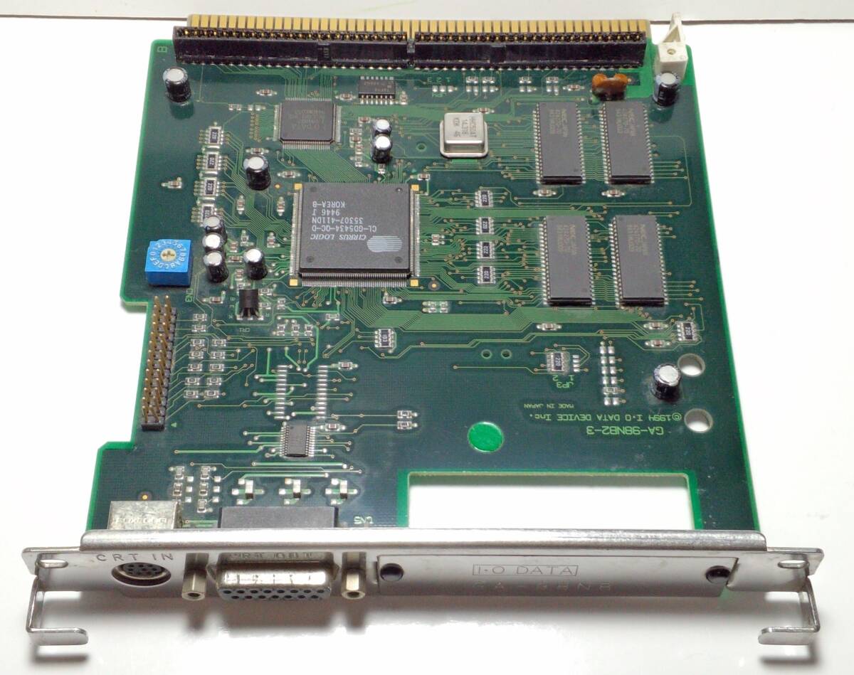 |
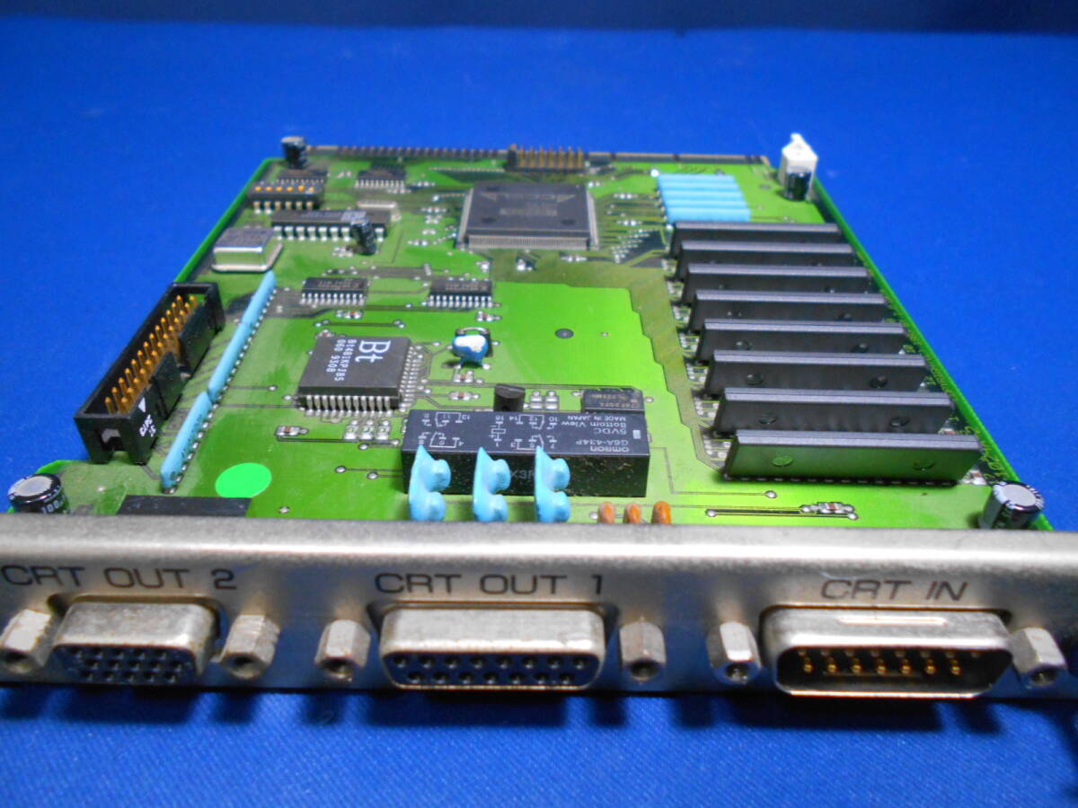
IODATA GA-98NB2 郵送無料 PS3-11 | Cirrus Logic graphics accelerator |
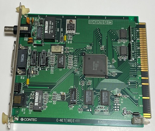 |
PC98 Cバス用 インターフェースボード CONTEC コンテック C-NET(98)E-11 LANボード | LAN Card |
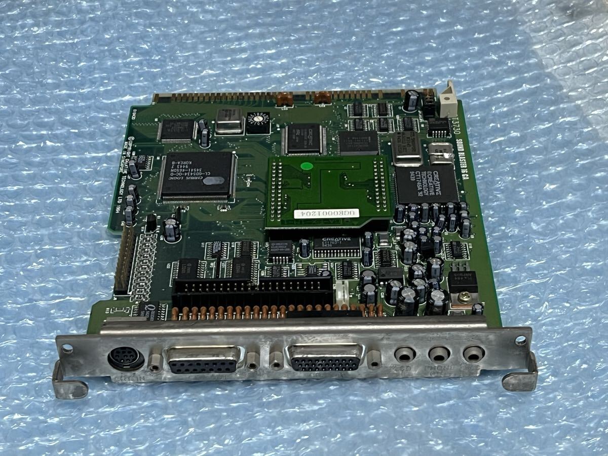 |
■Creative サウンドボード+グラフィックアクセラレータ CT3730 SoundBlaster 16GA【VRAM 2MB】 | A soundblaster for a PC-98! |
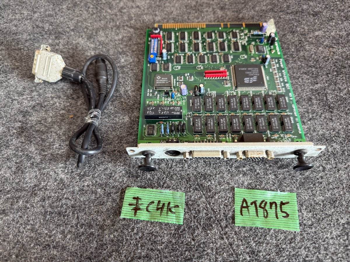 |
【送60サイズ】Canopus Power Window 801 REV B Cバス用グラフィックアクセラレータボード ※未チェック | An s3-based video accelerator |
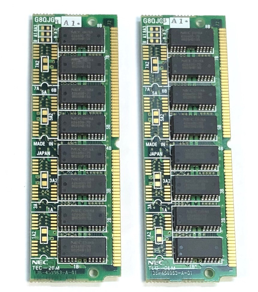 |
◇NEC 増設用メモリ TEC-26M PC98用 2枚セット | Some RAM for the PC-9801FA |
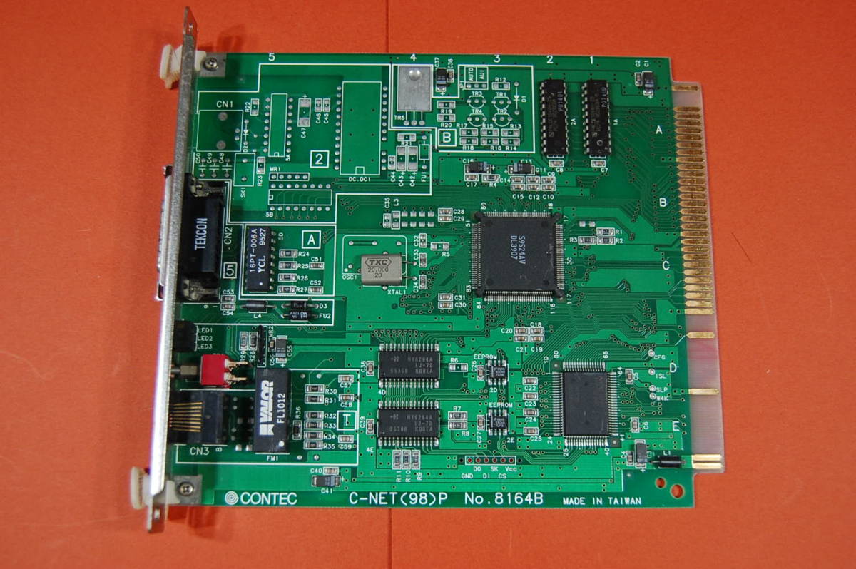 |
PC98 Cバス用 インターフェースボード CONTEC C-NET(98)P No.8164B LANボード サビ有り 動作未確認 ジャンク扱いにて 0343-0892 | Another LAN card |
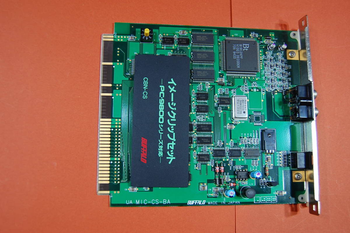 |
PC98 Cバス用 イメージクリップセット BUFFALO CBN-CS 現品のみ 動作未確認 現状渡し ジャンク扱いにて 3545 | Another LAN card |
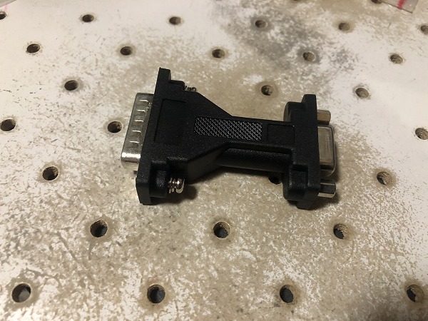 |
動作確認済 ネジ交換 モニタ変換アダプタ DSub15ピンオス-ミニDSUB15ピン(VGA)メス PC98 X68k等レトロPCに(CA230226) | A video adapter to standard VGA pinout |
 |
NEC PC-98用 グラフィック アクセラレーターボード ジャンク | Another Cirrus Logic video accelerator |
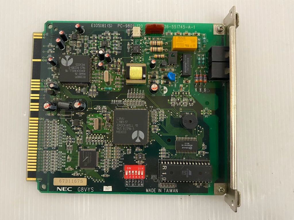 |
【中古】NEC G8VYS E105181S PC9801-120 管理番号ci434 | A modem, just for fun and future projects. |
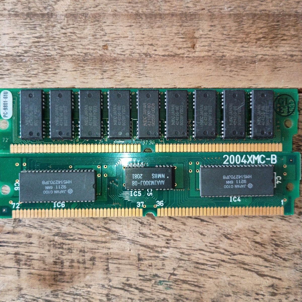 |
メモリ 2004MC - B PC-9801-61U | Some more RAM for the PC-9801FA |
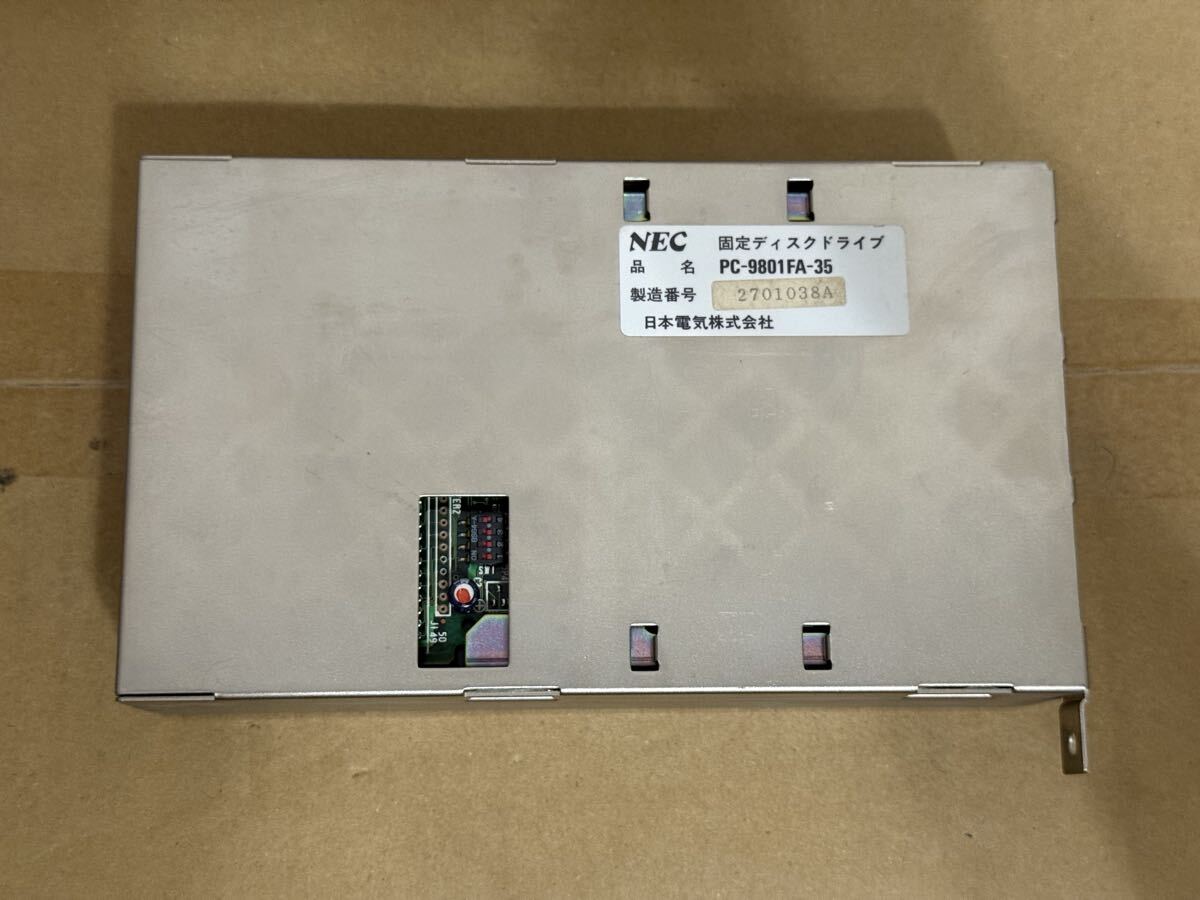 |
【DOS6.2で動作確認】PC-9801FA-35 PC-9801FA,PC-9821A A-MATE用SCSI HDD 100MB | An internal SCSI HDD for the PC-9801FA! |
It all looked great. Buyee had taken all the initial funds for the bid amounts and then consolidated my shipment. They then asked for the EMS payment and I sent that through also. It must have been at the 11th hour, when filling out the customs forms, that they realised they didn't know a $#%$#$% thing about electronics.
I received the following email:
Dear Customer,

This is the Buyee Customer Support.

Thank you for using our service.

We would like to inform you that your package【H2509179102】contains prohibited item for international shipping, which makes the whole package unable for overseas shipping.
-----------------------------------------
Order ID:【R25090402512
R25090302257
R25090402351
R25090403314
R25090403448
R25091004012
R25091100690
R25090902556
R25091302034
R25091504863】
Prohibited item:【Semiconductor】
-----------------------------------------

Please kindly choose one of the following options for your package:

OPTIONS:

I. Dispose of prohibited items that cannot be shipped, and send only the remaining items overseas.
(*If unopened, I agree to open and proceed with the necessary processing.)

Ⅱ. Ship all items in your package to a domestic (Japanese) address, such as your friend's address.

Ⅲ. Divide your package, ship the prohibited items domestically, and register the remaining items into your My Page as normal.
I knew a similar modem listed had a "you're unable to bid on this" banner, but everything I bid on I was allowed to purchase. Buyee already had my money and they'd bin everything if I didn't work out an alternate option? WTF?
Hello,
It is impossible that computer parts are prohibited. Can you please explain where this rule comes from?
Steven.
They took 24 hours to respond with...
We apologize for the inconvenience this has caused you.

Regarding your package number [H2509179102], we would like to inform you that semiconductor is prohibited by  the Japan Export Trade Control Order.

In addition, please be informed that all semiconductor products are considered prohibited items, except for commercially available pre-assembled laptops and desktop computers. It is extremely difficult for Buyee to determine whether products used in assembly (graphics boards, motherboards, conductors, audio equipment) require or not permission for export.
Semiconductor products? INCORRECT. I get that Japan doesn't want to export semiconductor-manufacturing items, of which it's blatantly obvious that these components are not, but how can they get these rules so wrong?
Thank you for the further information. Can you please provide a link to the actual laws from a Japanese government website? I'd like to learn more. Especially to know since when this law has come into effect.
Also, if you look at my account and purchase history on Buyee, I've been buying things like this for decades! I love vintage computers and there has never been an issue in the past. All items are always finished products and maybe only available in Japan, but definitely there are machines in Australia that use these parts.
Finally, this must be causing a lot of frustration with customers since we haven't been told of these new laws coming into effect and are allowed to buy things via your site and then lose all our money?
I would love to work with your team to get items certified so that we can continue.
They came back with a blanket statement...
We understand the importance of this matter to you.

In line with this package [H2509179102] we regret to inform you that the following items below are prohibited for international shipping:
* Semiconductor manufacturing equipment
* Semiconductor substrates
* Semiconductor devices for power control

The above-mentioned legal restrictions apply to a wide range of products, so products not listed here may also be subject to the restrictions.

For more information on the Export Trade Control Order, please refer to https://www.japaneselawtranslation.go.jp/en/laws/view/3389
Again, the rules apply to "raw materials" for semiconductor manufacturing and not completed modules for PCs! It's really sad that they don't have staff onboard who can determine the difference.
Hi again and thank you for the quick response.
Can you please confirm which items in package H2509179102 are prohibited?
This way I can understand to split/destroy/send domestically.
For future purchases, it would be helpful to understand how to determine which items would be prohibited in this category:
https://buyee.jp/item/search/category/2084045751
NO RESPONSE! And so I just sent it to a domestic address where it waits for me to grab on my next japan trip.
So, they answer is... if you can see green PCB in an auction listing, then Buyee will let you buy it, only to then tell you it's illegal and that you can't have it. The fact that they threaten to throw it in the bin, if you can't work out how to send it domestically in Japan, makes me a little sad.
Of course, this is the internet and people have already dealt with this problem before. Buyee even has a prohibited items list, of which semiconductors aren't listed. Even funnier, if they were, I'd disregard it as what I'm trying to buy are FINISHED COMPONENTS.
Even funnier, the law seems to be targeted at China and shouldn't even apply to us lowly nerds just wanting to upgrade our vintage machines!
And It Gets Worse...
I thought I'd try my luck and ask them about a listing. I'm after another PC-9801-86 sound card...
We highly understand the importance of this matter to you.

Regarding the auction [https://buyee.jp/item/jdirectitems/auction/j1208451738], we have confirmed that the auction is not blocked. However, we regret to inform you that we are unable to ship this item internationally due to the presence of a capacitor, which classifies it as a prohibited item.

Capacitors can pose significant safety risks as they may be flammable. In particular, liquid-filled capacitors can leak or burst, while solid capacitors may ignite and release smoke and harmful gases if they overheat or fail. These hazards could potentially lead to fire or explosion.

We appreciate your understanding on this matter and apologize for any inconvenience caused.

Please do not hesitate to contact us if you have any other questions or concerns.
Honestly. That is just icing on the capacitor cake.
Sharp X68000 CZ-612D Monitor Replacement Control Cover
Is it called a flap? A cover? A panel? I saw this X68000PRO unit in Japan on a trip in ... 2023? I found it on the shelf at Super Potato in Den Den Town Osaka with stickers all over it saying it was "for decorational purposes only" and that it "didn't work".
It's not visible above, is it? Sure, I forgot to take a photo of "before I purchased", as I managed to get it carted to Australia for a nominal fee, after being warned that it would really only sit on a shelf and do nothing. Since then I'd managed to get an external HDD going and other software, but I still really need to sit down and re-do all that, blogging at the same time since none of it was easy!
Anyway, the whole point of this post is that, as above, you can see the controls on the monitor. You're not meant to be able to, since there should be a fold-down cover.
This has perished, as many of them do, and I've been on the hunt for two years for a replacement. With nothing turning up in searches, I decided to try and TinkerCad it myself.
Look at that horrible mess? Fortunately, after you group it all, this comes out...
Ok, not bad. You'll note that nothing on the model should be a flat surface. This would've been so much easier if it was a 1084 Commodore monitor flap. Instead, Sharp, in their infinite wisdom (and beautiful design asthetics), decided that the entire bezel should be on a slight curve. Even the base should be curved... and I didn't do that. My CR6-SE printer isn't up to the challenge.
After around 15 attempts/adjustments/refinements/re-measurements/re-adjustments... I managed to produce this...
And you know what?
It's not 100%, but it works!
Here's the 3d model files if you want to print this yourself. I can also print one for you (even in beige!) if you need it. Looking at the list of x68000 monitors, it seems like this'll fit most of them?
Building an ARCNET (also Pure Data PDI 508+)
No, not an ARPANET, an ARCNET. I was recently given a box'o'junk from a friend who was cleaning up a telco engineers house and, honestly, had no idea what I was look at!
Turns out that it's a box full of ARCNET cards and some patch panels. Tiny 8-bit cards, longer 8-bit cards, huge 8-bit cards and even some 16-bit cards! A lot of them are Pure Data branded. Another name I'd never heard of... I did see a bit of SMC though!
I then went down a rabbit-hole of research... with everything seeming to indicate that these cards will simply work as the physical layer to whichever protocol you wish to run on top... so... let's try it!?
The Machines
First up we have a Toshiba T3200 286 Laptop. This thing has an 8-bit and 16-bit ISA slot in the rear, and the usual IEC-13 power plug. Quite the beast. Although it's old and tired, it'll work nicely with Microsoft LAN Manager. Turns out the drivers are already there!
Next up is a 486 DX4/100 and a P2-350. These are the usual desktop workhorses for writing floppies and testing old hardware. They've been sleeping for a while and are quite buried... so it'll be a bit of work to spin them up and test things.
SMC ARCNET PC270E
I chose this card as the first test article. There's a few in the box and they have the least dipswitches of all cards (that have dipswitches) that aren't PNP?. Turns out there's also a one-size-fits-all driver for this card and it's included in all systems I tried.
2. PC130 (SMC 8-bit driver): Newer 8-bit SMC boards with SMC90C63 controller
   chips use the PC130 family workstation driver. RXNET and TRXNET drivers
   can also be used. Boards in this group include the PC120, PC130, PC130E,
   PC220, PC260, and PC270E. The PC130 driver is a workstation only driver.
   If you wish to one of these boards in the server please use the RXNET
   or TRXNET drivers.
Being dipswitch-based, the jumper settings can be found here. Note that 0 is ON and 1 is OFF. That really confused me and I kept configuring the switches in the reverse order; wondering why nothing was working.
With a card in each of the machines, I started hooking up the cabling was exactly the same as an Apple LocalTalk network. RJ11 cables between nodes (any port on the cards) and terminating resistors at the far ends.
After setting some static IPs, I could ping from PC to PC! Unfortunately, the MSLANMAN 2.x installation on the 286 wouldn't ping in either direction.
SMC ARCNET PC260
This card works with the stock drivers but, with the driver installed, Windows 95 started to actually lag. Window and control re-draw rates slow right down, but the card still works. I can only really recommend using these in DOS or lower?
Although I did also try with Windows 98 and it worked fine... so it may have just been an incompatibility with the DX4/100 motherboard and/or resource settings.
PUREDATA PDI507
This seems to be very similar to the SMC above. It also includes BNC for when you don't feel like stringing RJ11 around the house.
PUREDATA PDI508+
This was a can'o'worms. I couldn't get a response from the card in any machine I tried. Windows has the drivers for these cards by default, but they always just showed up as driver failed to load.
There are hardly any settings, as it seems this is a very early PNP card!? Amazing... but frustrating as this EISA configuration document indicates that we need a custom configuration app to configure the settings:
Select desired Network Operating System or General Use to obtain valid hardware configuration options.
PDI508 ArcNet provides a configuration file CFGI508.EXE that will set all memory, I/O, and interrupts (also set through jumper JP2).
Oh great... well... I'm sure this blog will become the first (and only) hit for CFGI508.EXE on the web... as it's lost to time. Or is it? Turns out there's currently an auction for a 5 1/2" disk with, I assume, that exact configuraton app on it... but it's exorbitant. Then again, it's not like I haven't scoured auctions to find configuration apps before.
What is hilarious though, is that this auction has photos of the manual... and I stole them:
Hah.. look at that... default settings! Of course, it's the exact default of the earlier PureData/SMC cards.
| Option | Default value |
|---|---|
| Memory Address | 0xD000 |
| I/O Base Address | 0x2E0 |
| IRQ | 2 |
| Node Address | 0xF0 or 0xF1? |
| Response Time | 74us |
But how, you may ask, do we get the default settings to apply? Turns out there's a jumper on the card to clear the settings! stason.org to the rescue with the board layout! I assume it's a bridge-jumper and boot to clear... then power off, remove bridge, power up and go.
And well, it just worked with the default settings. Perfectly! But, you know what? I want the software... so I bought it...
and...
Yey! The files! I backed it up straight away. The configuration app works in the laptop... but not on the Windows 98 Dos Prompt. Either way, I can re-configure cards now!
And here are the files:
- An archive with two versions of the disk and a folder containing the contents
- The manual as a scanned OCR'd PDF
And finally, ACHEIVEMENT UNLOCKED: I've uploaded all of this to archive.org!
Hankai Tramway, Osaka – May, 2025
I'd been alerted that the oldest operational vehicle in Japan would be operating over Golden Week on the Hankai Tramway in Osaka. It's a Mo161 couldn't resist checking it out as they usually don't run during summer due to a lack of air-con...
I arrived at Shin-Imamiya-Ekimae via the Osaka Loop Line and didn't have to wait long for a south-bound service.
My goal was to get Abikomichi Station and view the tram depot. The Mo161 tour would start from there.
I tell you what, it was quite a ride! Definitely hold on if you're standing up. The fans were already starting to linger around Abikomichi Station, so I just loitered, watching the services pass as we waited for the star of the show to appear.
It was interesting to watch the terminating trams enter the depot and run around. Drivers would swap and the vehicles would re-enter service.
And ... well ... did I take too many photos?
My A6000 bit the dust at that point... I tried everything... but it felt like the shutter was sticking and it was all over. So I had to switch to my phone for the rest. Right as the star appeared!
And that was it... I was so pissed off at my camera that I went home and cried.
Osaka – May, 2025
Staying in the usual spot in Shin-Osaka, I ventured to the usual places... plus a few extras! First off, the usual shot from the balcony of the apartment of a now-common double-ended freight train.
They've started running them with banker engines now, thanks to the dip on both sides of the new "ume-kita" platforms at Osaka Station.
Shin-Osaka station was next... and, of-note, was a Haruka service with two different types of vehicles.
Next up, thanks to Osaka Expo, there's a direct shuttle to Sakurajima from Shin-Osaka operated by 323-series sets.
The set above had just finished it's run and was running-around near Higashi-Yodogawa station to come back into Shin-Osaka for the next service. I exited the station to check out the level crossing on the northern side of Shin-Osaka Station. This is only used for freight and the odd dead-head movement.
A service was also running into Ajikawaguchi via the main lines...
But yeah, back to the freight line...
Osaka Higashi Line
Although I'm sad you can't cross the bridge on-foot anymore, I'm happy for the line and being able to travel on it! I got up at sparrows-fart to do a Hard-off tour and that allowed me to see the morning services on the line.
Hilariously, I managed to catch the next train to Hidara Station to see the same freight consist shunting around.
But then... I was off on something new!
Kashiwara Station And Surrounds
There's a hard-off just to the west of Kashiwara Station, and I had gotten there too early... so... instead? Train-spotting!
The Kintetsu Domyoji Line terminates here, so there's a lot of action as the shorter EMUs run in and out in the morning peak. The line runs south across a picturesque bridge before getting buried in the Kintetsu network. Thanks to having a bit of time, I dawdled around, enjoying the morning sunlight.
It was meant to be an un-eventful stroll to the riverside, but was quickly interrupted by a weird 'sloshing' sound coming from one of the canals...
I wonder how often these guys get fed? They were hunnnnnngry!
I was too distracted by the fish to realise there were cool shots behind me...
But anyway, I continued to the river.
Ok yup. This was the right decision.
Kashiwara-Minamiguchi Station is perched above the roadway, right before the river bank.
Perfectly model-able! From there... more wildlife...
And then hard-off... treasure.
Limited Express Mahoroba
There's a new limited express through to Nara from Osaka Station, operating via the Osaka Higashi Line!
That's all... oh, and some freight in the same place...
Oh... and the tea train!
There was also then a test-run afterwards... which I missed. I should've loitered with the other tecchan who wasn't moving!
Osaka Metro Chuo Line 400 Series
This 400-series star-wars-ian EMU has been introduced to take people over to the Expo amongst the man-made islands. Fortunately, at the other end of the line there's a beautiful station before the beautiful mountain range.
If you look close enough, you can see a Kintetsu train climbing the mountain.
Random Photos
Search
Tags
Ads
Links - Click for details
- Abandoned Rails (Japan)
- AIRLINE (Shinkansen Photography)
- Akihabara Station
- annexpressのブログ
- Australian Model Railway Magazine
- DCC普及協会ホームページ (Japanese DCC)
- Dead Section (Japanese Track Diagrams)
- Delicious Things (Japanese N Scale DCC)
- Densha Wotorou
- Digital Direct for Windows (DCC Server)
- Don's Dream World – AMAZING N Scale Japanese Layout
- Hatena::Diary
- Japanese N-Scale Modeling Forum
- JR Chiisai
- Kaz-T's blog レインボーライン (Rainbow Line)
- LED Resitance Calculator
- Masioka
- Poppondetta Blog
- RailFan Magazine, Japan
- Railmind
- Railway Travelers' Room
- Serenity Valley
- Shashinka Ichiban
- Shuzuku
- Sumida Crossing
- The next station is…
- Tomix N Gauge Track and Japanese N Gauge Trains
- TT Forums (Transport Tycoon Deluxe)
- 名鉄尾西線の貨物列車 (Nagoya: Meitetsu Freight)
- 日本型Nゲージ DCC改造例のご紹介 (Okiraku DCC)
- 泰 茅 轍 道 (Taichi Railway)
- 箱庭登山鉄道製作記 (Hakone-Tozan Layout Blog)
Archive
- February 2026
- January 2026
- November 2025
- October 2025
- September 2025
- August 2025
- July 2025
- June 2025
- February 2025
- January 2025
- November 2024
- September 2024
- August 2024
- July 2024
- June 2024
- May 2024
- April 2024
- March 2024
- February 2024
- December 2023
- October 2023
- September 2023
- August 2023
- July 2023
- June 2023
- May 2023
- April 2023
- March 2023
- December 2022
- November 2022
- October 2022
- April 2022
- March 2022
- February 2022
- January 2022
- December 2021
- November 2021
- September 2021
- August 2021
- July 2021
- May 2021
- March 2021
- February 2021
- January 2021
- October 2020
- September 2020
- August 2020
- July 2020
- June 2020
- May 2020
- April 2020
- March 2020
- January 2020
- December 2019
- November 2019
- October 2019
- September 2019
- August 2019
- July 2019
- June 2019
- April 2019
- March 2019
- February 2019
- January 2019
- December 2018
- November 2018
- October 2018
- September 2018
- August 2018
- July 2018
- June 2018
- May 2018
- April 2018
- March 2018
- January 2018
- December 2017
- November 2017
- October 2017
- September 2017
- August 2017
- July 2017
- June 2017
- May 2017
- March 2017
- February 2017
- January 2017
- December 2016
- November 2016
- October 2016
- September 2016
- August 2016
- July 2016
- June 2016
- May 2016
- February 2016
- November 2015
- October 2015
- September 2015
- August 2015
- July 2015
- June 2015
- May 2015
- April 2015
- March 2015
- February 2015
- January 2015
- December 2014
- November 2014
- August 2014
- July 2014
- May 2014
- April 2014
- March 2014
- December 2013
- November 2013
- October 2013
- June 2013
- August 2012
- April 2012
- March 2012
- February 2012
- November 2011
- October 2011
- September 2011
- July 2011
- June 2011
- May 2011
- April 2011
- March 2011
- February 2011
- January 2011
- December 2010
- November 2010
- October 2010
- September 2010
- August 2010
- June 2010
- May 2010
- April 2010
- March 2010
- February 2010
- January 2010
- December 2009
- November 2009
- October 2009
- August 2009
- January 2009
- December 2008
- November 2008
- October 2008
- September 2008
- July 2008