


 Melbourne BG SCS Train Timetable


2023 Prius Z – System Malfunction Contact Dealer
After enjoying the last 10 years with my 2015 ZR Corolla, it was time to save the environment and go hybrid! I'd rented one of these machines in Kagoshima in the past, and loved it, so decided to bring one over privately. To help the search engines, it's an MXWH60/M20AFXS.
Of course, I can never have nice things. Sure, it's got a little bit of damage to the front-left wheel arch... but the real issue was to come. Driving it home from Canberra to Melbourne saw it throw up an error (System Malfunction Visit Your Dealer) on the dashboard preventing me from seeing the power system status diagram. It also threw out most of the lane functions... but adaptive cruise still worked perfectly.
A lot of research was done... and a new auxilliary battery was installed, but the problem persisted. It was noticed, after the battery change, that the error pissed off for a while and came back 30 minutes down the track. I considered taking it to a local Toyota dealership here in Melbourne, but decided I could try and sort it out myself. So... first step... ODBII Bluetooth Reader and App.
Crap photo, but that bit top-left is the steering column cover, and the ODBII reader is in the ODBII socket... so yeah, it's to the lower-right of the steering column, down past the bonnet (hood?) latch. With this installed, I followed the steps of the associated Android App:
Actually, I lie... I first had everything ticked... but realised the errors were only coming under the LKA/LDA node, so the shot above shows just that ticked... made it much faster when re-running. But yeah, let's zoom in on that error...
So, it's C1A77(96) - LKA/LDA - Error "Show warning to user". That's not CIA, it's C1A and that initially lead me down a "there's nothing on the internet" rabbit hole. After simply tapping the link, as it says it'll search the internet, I came across this first link from a (Russian?) tech note from Toyota?
| Code | Detection Item | DTC Detection Condition | Trouble Area |
|---|---|---|---|
| C1A7796 | Steering Touch Sensor Component Internal Failure | When all of the following conditions are met:
|
Steering vibration and heater ECU (Steering wheel assembly) |
So, it's an issue with the ECU inside the steering wheel. The what? My steering wheel has its own digital brain? And it's having an issue with the pressure sensor in the steering wheel? That's interesting, because prior to the malfunction it knows perfectly-well if I have my hands on the wheel (or not) and happily throws the usual "put your goshdarn hands back on the goshdarn wheel or I'll make you drive by yourself"
Anyway... so... I need a new ECU for my steering wheel? sure!
Officially, it's part #1 in that diagram... and it turns out you need to pull the entire wheel apart when you want to install it. Just for fun, I popped open my steering wheel to find out what unit was installed. I wanted to compare model numbers with the part I needed to buy:
I do note that this unit number 864A1-47030 has been superseded by 864A1-47031. Does this mean I have the buggy old version that throws random errors? I went ahead and purchased the new item from YoshiParts and waited for it to arrive.
In the meantime, I scoured the web for other people having the same issues. It turns out that there are a few blog posts from owners in Japan noting a similar issue. Supposedly they were told to pop the Steering Heater fuse for 90 seconds and the error should disappear. This should cut the 12v to the steering ECU and reset any error conditions. I'll note that this didn't work for me! Other's have mentioned that they received a whole new steering wheel via warranty and the problem disappeared. Of course, I had no warranty.
Replacing the Steering Wheel ECU
The part arrived and looked brand new! This came as a great relief as I had no idea what to expect from YoshiParts. Officially I can totally vouch for them on price, service and super-quick postage!
I disconnected the auxilliary battery in the boot and let the car sit for 15 minutes. This is to prevent the Air Bag from deploying whilst we muck around with it.
First step, you'll actually need to pop off the airbag/horn unit. This is held down by three spring-loaded pins which are released by metal clips accessible on the left, bottom and right sides of the steering wheel. In fact, if you look up above to where I was checking out the ECU installed in my car, you can see the three thin chrome clips. You'll need to press against these to release each of the three pins of the airbag/horn unit.
The first one to attack should be the bottom one. It's accessed through a tiny hole on the right-side of the underneath of the steering wheel. You'll need a long metal pole... be that an allen key, or a flat-head screwdriver and you'll want to find the hole on the under-side of the steering wheel and press the tool into it. After around 30mm, as long as you're running the tool as if it's aiming towards the driver, you'll hit a metal spring of which you can compress. Once you've compressed it enough, the horn button component will "pop up" at the bottom.
The hole is shown above, as seen from the underside of the steering wheel. Below you can see the end of a torx screwdriver pushing up the spring clip from below. This is the goal! Just close your eyes and gently apply pressure until you find the spring.
Once it's up, you then need to do the same via the left and right access panels either side of the column next to the stalks. Use your fingernail or a plastic utensil to remove them.
Shown above is the left side of the steering wheel with the cover still in place. You can see where to shove a tool in to pop the cover off. Once off, you can shine a torch in there to see the metal/chrome springs.
Above is cheating as the steering wheel is a spare which I accidently bought, thinking it might fix the issue. But you can see how easy the side parts are to press in. You can even use your finger!
With the three spring-clips undone, you can flip the horn/airbag unit over and unclip the airbag connector. You'll need to slide in a plastic utensil to lift the orange 'cap' from the yellow body. It only needs to lift 1-2mm. Once it's raised, you can then pull the whole plug out of the unit. You then need a tiny screwdriver to slide into both the plastic retension clip and the horn spade clip to slide them off. As with everything Toyota, there's a method to it all and NO FORCE IS REQUIRED. If you're finding it difficult then you're doing it wrong! You can now put the horn/airbag unit to the side.
I didn't take a photo, but there are two plugs to unclip (top and bottom) and then the huge 10mm allen-key socket to deal with in the middle. I had to buy a breaker bar to get it undone!
Once undone, the bolt comes out and the steering wheel can be removed. I've heard it should be on hard, but mine literally slid off.
I removed the housing...
And replaced the ECU. Everything went back in the car and settings were reset for all driving assitance packages. Before-long, bang... System Malfunctionnnnnnnnnnnnnnnnn...
Disabling LDA as a 'fix'...
Even though I'm sure I'd tried this prior to replacing the Steering ECU, I found that disabling LDA stopped the error from appearing.
This aligns with the web page at the start indicating that a condition for the error is that LDA is active and that the warning type is set to vibration. The car continued to function, but with a large orange warning on the dash that LDA was turned off:
And, I mean... I could deal with that. I drove to Canberra and back with everything (except LDA) working nicely. I don't know if I even want LDA to be active? I then stumbled across this Reddit thread titled 'Steering wheel assembly touch sensor needs replacement.' and realised I had one (or two) more options up my sleeve. I could still replace the entire steering wheel, in case it was an issue with the touch sensor... or replace the "spiral cable" in case that had gone faulty. In fact, the other user on that Reddit post was waiting on a spiral cable replacement as we chatted and I decided that was my next step.
Looking at the service manual didn't quite confirm this?...
And the fix?
Riiight... Hah.. replace everything from left to right... but actually, it only reckons to replace the steering wheel assembly? What about that wretched spiral cable?
Clock Cable / Spiral Cable
This was actually hard to find on YoshiParts! It's buried in Switch & Relay & Computer section on this page and listed as part number 84306.
I only bought the spiral cable, and not the steering position sensor... and it seems I accidently did the right thing! It turns out the steering position sensor contains a security key that needs to be programmed into the main vehicle ECU if you change it! So yeah, although the steering sensor and spiral cable are massively intertwined, you really only want to replace the spiral cable if you do this!
And yeah, replacing the cable was NOT stress-free. I did the same tear-down as above to get to the cable... further removing the steering column housing. This requires three screws to be removed (don't forget the one underneath!)
Once the housing is off, you can remove the sensor + cable by unclipping it at 12-oclock where it connects to the steering column.
These photos are really useless... but there's only one clip top-center holding the unit to the cluster. Once it's off, you can remove and replace the spiral cable from the steering sensor.
One Note on removal: There are four cables to unplug along the bottom. The steering sensor has slack on its cable which can be unclipped, so do that first. Finally the airbag plug needs to be unclipped by sliding a tool down the front of it's plug. Slide the tool into the slot at the socket-end of the plug, not the wire-end! Once you've inserted the tool as far as it'll go, simply slide the plug away from the socket. Again, there will be no need for force! The main goal is that you should NOT slide the tool in from the 'wire side' of the plug.
At this point, the documentation points out that you must not change the angle of the steering sensor when changing the cable. The sensor must stay at position 0 and this can be achieved by locking it with the included locking pin.
So yeah, above, rotate the existing cable until the pin can be installed. Once locked on, unclip the 6 clips around the sensor to detach the cable. Then simply clip the new cable straight on top! No issues really! I have no idea how one would actually manage to set the steering sensor to anything other than 0 degrees...as it's totally locked to the sprial cable. You'd have to actually rotate it a full 180 or -180 to be able to clip it together and you'd sure know if you've done that?
Either way, the car was put back together with this new spiral cable and, 2 hours of driving later... NO ERRORS!
Moral of the story? Buy a car under warranty that was released in your country. But damn, I love this car!
Yamaha P-95B – No Sound – Repairs
Have been looking for a midi-enabled nice-sized weighted-key keyboard for a while and saw a P-95 on FB Marketplace going for AU$500. I felt it was a bit steep for a pretty-old piece of kit, so I googled a little... initially just to confirm it had MIDI ports.
I then stumbled across this absolute cracker of an ad for a P-95 at a local music shop:
Turns out Music Swop Shop in Carlton is a treasure-trove of 2nd-hand music equipment... and they'd decided this unit wasn't worth repairs. Likely SMD repairs, they say?...
The unit was lugged home and open-brain-surgery ensued. The keyboard would react to note presses... I could see that record would flash until a you started playing... so the keys were operational and the panel seemed ok. The main issue had to be voltage/audio amplification? It turns out that the X8828 Amplifier Board seems to fail a lot... to the point where there are multiple "send it to us and we'll fix it" services!
I popped the board out of my unit and ... it looked bad. That crap cleaned off, but I was getting a lot of shorts across a LOT of the shitty little blue electrolytic caps? This turns out to be quite a common problem! That thread is hilarious, and I must add my repair to it. So many people with so many dried up dead caps.
With some of the caps, a slight touch from the top-side would actually push the leg through and detach the pad on the bottom-side! Hacks were put in place, thanks to enough space being available inside the piano.
All caps were replaced, for good measure. When reinstalling everything you need to BE VERY CAREFUL with the ribbon cables. I don't know if it was me or the previous repair-man, but the silver wires were starting to de-laminate at the ends where the ribbons plugged into the sockets. If you then put them in at an angle you could risk folding the silver back up on itself. Just be very gentle and precise when putting it all back together... otherwise you'll do what I did and dismantle it 10 times as the unit failed to respond every time I re-assembled it!
Anyway... I eventually got the ribbons in cleanly and then it all just worked perfectly!
Even MIDI-OUT!
So yeah, if you have a vintage Yamaha like this, then replace all the caps.... as the caps that aren't dead yet won't have much life in them either.
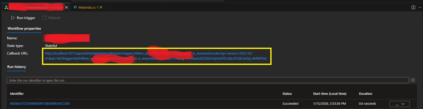
Getting A Locally Debugged Logic App’s Callback URL
For those of you who want to locally automate testing of Logic Apps running in VSCode, this post is for you! Across the web, there are people asking for a dynamic way to get the Callback URLs for locally debugged logic apps. They run via func.exe and it has been previously thought that the only place to get the URL with the required 'auth' signature was the overview window of the workflow:
Fear not! I've used the development tools to rip apart VSCode and have worked out that our trusty local func.exe exposes all the webservices that Azure does! The full list of services available is over here. Specifically endpoints to list workflows, workflow triggers and then trigger Callback URLs with full signatures!
internal class LogicAppDetector
{
    private string base_url;
    public LogicAppDetector(string baseUrl = "http://localhost:7071/") {
        this.base_url = baseUrl;
    }

    public List<LogicAppWorkflow> GetListOfWorkflows()
    {
        var workflowListJson = WebClient.DownloadAsString(base_url +
            "runtime/webhooks/workflow/api/management/workflows");
        return JsonSerializer.Deserialize<List<LogicAppWorkflow>>(workflowListJson);
    }

    public List<LogicAppWorkflowTrigger> GetWorkflowTriggers(string workflowName) {
        var triggerListJson = WebClient.DownloadAsString(
            base_url + "runtime/webhooks/workflow/api/management/" +
            "workflows/" + workflowName + "/triggers");
        return JsonSerializer.Deserialize<LogicAppWorkflowTriggerContainer>(triggerListJson).value;
    }

    public string GetWorkflowCallbackUrl(string logicAppWorkflowName)
    {
        var wf = GetListOfWorkflows().FirstOrDefault(x => x.name == logicAppWorkflowName);
        if (wf == null) {
            throw new Exception(
                "Couldn't find workflow [" + logicAppWorkflowName + "] in the list?");
        }
        var trigs = GetWorkflowTriggers(logicAppWorkflowName);
        if (trigs == null) {
            throw new Exception(
                "Couldn't find triggers for workflow [" + logicAppWorkflowName + "]?");
        }
        if (trigs.Count() != 1) {
            throw new Exception(
                "Incorrect trigger count for workflow [" + logicAppWorkflowName + "]" +
                " ... count was " + trigs.Count() + "?");
        }
        var callbackUrlJson = WebClient.PostJsonData(
            base_url + "runtime/webhooks/workflow/api/management/workflows/" +
            logicAppWorkflowName + "/triggers/" + trigs[0].name +
            "/listCallbackUrl", null); //payload is actually NULL.
        var callbackData =
            JsonSerializer.Deserialize<LogicAppWorkflowTriggerCallbackUrl>(callbackUrlJson);
        return callbackData.value;
    }
}

internal class LogicAppWorkflow
{
    public string name { get; set; }
    public string definition_href { get; set; }
    public string href { get; set; }
    public string kind { get; set; }
    public object triggers { get; set; }
    public bool isDisabled { get; set; }
}

internal class LogicAppWorkflowTriggerContainer
{
    public List<LogicAppWorkflowTrigger> value { get; set; }
}

internal class LogicAppWorkflowTrigger
{
    public string id { get; set; }
    public string name { get; set; }
    public string type { get; set; }
}

internal class LogicAppWorkflowTriggerQueries
{
    [JsonProperty("api-version")]
    public string apiversion { get; set; }
    public string sp { get; set; }
    public string sv { get; set; }
    public string sig { get; set; }
}

internal class LogicAppWorkflowTriggerCallbackUrl
{
    public string value { get; set; }
    public string method { get; set; }
    public string basePath { get; set; }
    public LogicAppWorkflowTriggerQueries queries { get; set; }
}
You'll just need to plug in whatever you're using for Web Requests to GET and POST. Also make sure that the actual Logic App is running/debugging in VSCode!
Leave a comment if you have any issues.
ATX12VO – MSI MPG Trident AS
So this rabbit hole got very deep, very quickly! Bought a new machine... a smaller form-factor unit with great asthetics! Little did I think about any upgrade paths.
It came with an 8gb 4060 Ti which has been flawless for my needs, but I'm thinking I need 16gb... so... as that it's got enough room inside for a better video card? Why not?
I chose an RTX 5070 Ti based on price and RAM. As I was buying the card, the cashier told me I'd need 750+ watts of power and tried to sell me a new supply on-the-spot. Instead, I decided that I'd get home and check what was in the tin first, as brief googlin' indicated that some Tridents came with a Gold Power Supply.
But nope... my MSI Trident contained a 500w SFX. So, I went back to another PC store that afternoon and bought a Cooler Master V850 SFX Gold. A nice amount of power for my card!
Unfortunately, no amount of cable-jiggery-pokery would get the new ATX motherboard power cable to connect to the motherboard power socket? What gives? It turns out the Trident uses an ATX12VO power supply! A short-lived game-over ATX standard that Intel tried to push. They failed so-much-so that the standard has already been forgotten about. I take it I didn't realise how old this PC already was when I bought it. It was a refurb, so it probably lived its life in a gaming cafe.
Trying to find an exact ATX12VO SFX PSU with the correct wattage turned out to be futile. They just don't make them anymore! I started considering re-wiring the old plug from the old supply onto the new PSU, but there's a single pin that doesn't match: +12VSB. This wire is a constant 12v from the power supply to the motherboard for ancillary services. Things like charging USB devices when the machine is off (which could actually cause a lot of current draw?) and the power switch... which, thanks to ATX soft-power, needs a constant current trickle to determine if you've pressed it! I could possibly buck-convert the DC, like other people have tried... there's even a project for it here.
The googl' rabbit-hole went deeper and intially I found that Corsair has a custom cable, but I'd already purchased a Cooler Master! I then stumbled across Moddiy's site where they mention Cooler Master and ATX12VO on the same page! They'll create the custom cable for you with inline 12v boost for VSB!
In that last shot it looks like a snake processing a big meal, thanks to the heat sheath.
Cooler Master V850 SFX Pinout
The cable came with no mention of which end was for the PSU. Both ends have the same "ATX plug shape", so I didn't want to plug the damn thing in backwards. IF I had attempted to plug it in, I would've realised that only one side will go into the motherboard, but I was averse to doing it that way.
Instead, I started reversing both ends of both the power-supply-included cable and the new Moddiy cable to work out what was what. Turns out I really only needed to reverse the Cooler Master original cable on the plug, not the socket.
So, looking at the above cable, as it's shown, you get the following pinout:
| 10P M/B cable (not socket), looking at the plug with the notch facing up... | ||||
|---|---|---|---|---|
| 12v | 12v | -12v | +5vsb | POWER_OK |
| GND | GND | GND | 12v | 5v |
And that means the end of the cable with the 'top-central' pin missing is the Power-Supply side. The end with the 'loop' wire is the motherboard side. Everything routed through to the other end, as expected to match the ATX12VO standard.
Of course, the +5VSB didn't, as it goes through the inline DC converter which prevents a continuity test.
Mounting It In The Case
After taking the side panel off the machine, you'll find that the existing power supply has a mains lead running from the rear of the case to it's mounting bracket at the front.
First up you'll want to remove the 4 screws under the machine to release the mounting bracket.
Next, you want to gently push the power supply and bracket up, compressing the cluster of cables above to clear the bottom edge of the case.
Make sure to move any WiFi antennae out of the way! Once clear, the power supply can be lifted out via the base, disconnecting all cables (2 motherboard and 1 PCIE) at the same time.
From here, remove the base and attach it to the new power supply. Make sure that the notch is facing right when the power supply fan is facing you. This will allow the fan to line up correctly with the vent on the other side of the case.
Also make sure you switch the bloody thing on if it has an external switch like this one does! There'll be zero access to that once it's installed. Finally, connect the power cable and slide the new supply back into the case.
Line up all the WiFi antennae so you don't pinch them on installation! Route the required power cables to the expected sockets. I actually considered running the SATA power to the drives to take the pressure off the motherboard's voltage regulators... but maybe I'll do that later.
Power Test
With it all installed... I just sent it...
A healthy click from the relay inside the new power supply (that's a new feature!) and we're off!
Wooooooooooooooo hoooooooooooo.
New GFX
This is nearly Apple-level packaging. Very schmick!
They also totally overdid the protective film! I suppose they wanted to have ASMR vids from the streamers.
Installation is harmless... just watch out for sharp case edges! Oh, also, the new PCIE 5.1 Power Cable has a right-angle connector housing which is optional:
You can pry it off by getting a tiny screwdriver in those side clips. Anyway... the card was in... what to do?
WIN! Nvidia installed new GFX drivers automagically and it all JustWorked(TM)! A final test:
Perfect 4K 10000fps.
Apache Spark 2.4 EOL
EOL = End of Life. It's dead, Jim. No longer supported. If you get this error in Azure Synapse, then your Apache Spark Pool worker is trying to load v2.4 (INSERT_VERSON_HERE, really... as I'm sure this'll happen in the future as the window rolls) which has been deleted.
RUNTIME_CONFIGURATION_ERROR_VHDOVERRIDENOTFOUND: Livy session has failed. Session state: Error. Error code: RUNTIME_CONFIGURATION_ERROR_VHDOVERRIDENOTFOUND. Cannot find vhd based on override: Message=The system did not find a VHD copy in the system for creating the ClusterName=12341223-5555-4444-3333-63c446fe4d8b, Workspace=synws-d-e-v-d-e-v-01, Subscription=, Location=australiaeast, isVhdOverride=True Source: Dependency.
I'm putting this on the web so others can googl' for it. I had no results and it burnt 1/4 of my weekend. Re-deploy your pools with:
Update-AzSynapseSparkPool -WorkspaceName ws_name -Name pool_name -SparkVersion 3.4
And... cross your fingers. Of course, if you've tried to delete a pool with notebooks attached, then you'll have ERROR, POOL IN DELETED_FAILED STATE and you'll need to create a new temp pool, associate ALL notebooks, delete the old and then rename the new... or create another with the old name and then switch them all back and delete the new... or something. It's a monday problem.
Python: Close Files If You’re Going To Open Them
I've been trying to archive some videos off Youtube lately, using yt-dlp. It's an amazing tool, but my target files have been episodes in parts. Usually four parts and Plex really hates jogging through... so what to do? Combine the files together with ffmpeg. The code was meant to be pretty simple (and 98% of it was written by ChatGPT... whoops)...
def concat_episodes(episode_name, concat_files):
    plfile = "file_list.txt"
    f = open(plfile, "w", encoding="utf-8")
    for filename in concat_files:
        f.write("file '" + filename + "'\r\n")
    concat_command = f"ffmpeg -stats -safe 0 -f concat -i {plfile} -c copy '{episode_name}'"
    print(concat_command)
    subprocess.run(concat_command, shell=True)
But no amount of wrangling would get ffmpeg to work. The concat filter kept throwing: Invalid data found when processing input. No amount of "-safe 0", relative paths or absolute paths worked! No permissions... no cwds or shell arguments. If I let the python script drop to the shell, then the same line pasted (since I printed it out) worked perfectly fine! What the?
OH RIGHT. I missed the memo that I should be closing a file so that it lands on disk... prior to trying to open it in another process!:
def concat_episodes(episode_name, concat_files):
    plfile = "file_list.txt"
    f = open(plfile, "w", encoding="utf-8")
    for filename in concat_files:
        f.write("file '" + filename + "'\r\n")
    f.close()
    concat_command = f"ffmpeg -stats -safe 0 -f concat -i {plfile} -c copy '{episode_name}'"
    print(concat_command)
    subprocess.run(concat_command, shell=True)
The file was still open and not flushed to disk... so ffmpeg would always open an empty file! This has been a public service announcement.
Replacing the ear microphones on a Sony Aibo ERS-7
He'd arrived a few weeks back and gets energised a few hours per week... but he's a bad dog! He says "Good bye" in repsonse to me saying "Hello Aibo" and I'm going to blame him first... it can't be my mumbling? Can it? Just to be certain, I browsed around and found a DIY Repair Guide on Aibo Doctor. I quickly ordered a selection of microphones from element14 and got to work. Canine surgery is daunting!
The Microphones
As I always manage to get my orders wrong, I went ahead and ordered a selection of Microphones.
Note that an ERS-7 Aibo needs 6mm microphones, so you can see that one set is already incorrect. Next, there's directional and omni-directional. The microphones in Aibo are omni*, so I settled with the KECG2742TBL-A units.
Disassembling Aibo's Visor
Following the instructions here, one can disassemble Aibo's head to get to his ears. First step, remove the rubber earlobes by stretching them over the silver joint. Next, open his mouth and remove the two screws.
With these two removed, you can un-hook the rear of the bottom half of his head. This shell is not directly connected to his bottom jaw, so open his mouth fully and then push the whole lower-half back. With it unhooked, you can then bring it forward again and bring it over his jaw. With this piece out of the way, it's back to the front of his head where we need to remove the two outside screws on the metal plate inside his nose.
With those two out, you then need a longer screwdriver to get to the two screws deeper inside his skull. They're on either side of where his jaw would attach near his ears. See the image below, one screw on one side is in focus.
Finally, there's a clip on each side just in front of his ears, holding the visor on.
Very gently pry this open and the visor should lift up. You now have the option to disconnect all the cabling, but instead I just let it rest forward. Make sure it doesn't put undue pressure on the ribbon cables inside.
You now have access to the ear joints.
Disassembling Aibo's Ear Joints
Ok, this isn't the actual ear/microphone yet... before we get to that, there's a bit of fidgeting required to get the ear joints disassembled. When following the next steps, at no time will you need to apply excessive force! Doing so will most-probably damage poor Aibo. The ear joints are a two-part component and are built to be assembled/disassembled with ease. If you look at either side of Aibo's ears, you'll see that one side has a fixed arm and the other has an arm that slides backwards. The fixed arm is at the front and also has a little actuator (metal bar with notch) that is the mechanism that flaps Aibo's ears around when he's playing.
So, back to the joints: two pieces, first is removed by sliding the rear arm further to the rear. From there, you can grab the whole circular joint and unhook it from both front lugs. There's a lug in the actual main arm and a lug in the little black actuator arm.
The image above doesn't really help to explain how to undo it. The movement is one-shot and you can see in the photo above that the black actuator is on the left. This means that you're looking at Aibo's right ear and that you'd grab the top silver circle and slide it gently to the right (rear of his head) until both lugs are clear on the left. Once done, you can then slide off the rear shield.
From here, it's a single screw and the microphone + housing is free. Make sure you also unhook the cable!
Replacing Aibo's Inner-Ear
With the microphone unhooked and unscrewed, the silver shell can be lifted off (gently) by applying pressure to the joints that hold it on. With this off, you can really see what condition Aibo's ears are in!
From here, you can slide the microphone out, just enough, to be able to de-solder and solder a new component.
As you can see, I cheated and used the phone the new microphones came in to hold them in-place whilst soldering. I used the datasheet to make sure I got the polarity the correct way around, assuming that red was positive.
With everything wired up, the microphone was pushed back into the housing and re-assembled. Make sure that you have the wires in the correct groove according to the side the ear has been removed from!
Finally, as per above, there is absolutely no need for excessive force on any part of this assembly. I found that, once trying to re-fit the visor, it wouldn't sit flat! Turns out that I'd assembled the rear part of the ear-joint incorrectly and only one side of the guides was actually in the right spot!
If you look above, you can see that the left guide is sitting above the plastic strip that it was meant to slide onto! This meant totally dismantling that ear again to pull that part back and slide it back on again! Painful, but required.
Can Aibo hear me now?
Nope, same as before! Turns out you can just use Clinic Mode to determine if his microphones actually really need replacing! I should've done this first, but I also sorta wanted to play doctor and see what his insides looked like!
Smushing JSON into submission!
I don't even know how to describe this operation on JSON. The basic idea is that we want to deserialise a stream into something legible, without creating a class for each item in an array. json2csharp believes that each item should be an array since it sees them all as individually named classes. Let me prove it! Here's a chunk'o'data:
{
    "trainCount":122,
    "requestTimestamp":1601124556789,
    "responseTimestamp":1601128156789,
    "nextUrl":"https://junatkartalla-cal-prod.herokuapp.com/trains/1601128156789",
    "trains":{
        "8":{
			"id":"8",
			"from":"LR",
			"to":"HKI",
			"title":"IC8",
			"latitude":60.172097,
			"longitude":24.941249,
			"speed":0,
			"direction":0,
			"category":"IC",
			"status":"1",
			"delta":60,
			"trainType":"LONGDISTANCE",
			"updated":1601127783841,
			"action":"deleted"
        },
        "9":{
			"id":"9",
			"from":"HKI",
			"to":"LR",
			"title":"S9",
			"latitude":60.571148,
			"longitude":25.199523,
			"speed":0,
			"direction":0,
			"category":"S",
			"status":"1",
			"delta":60,
			"trainType":"LONGDISTANCE",
			"updated":1601128143878,
			"action":"modified"
        }
    }
}
So, if you slam that JSON into json2csharp, you'll get the following:
    public class 8    {
        public string id { get; set; }
        public string from { get; set; }
        public string to { get; set; }
        public string title { get; set; }
        public double latitude { get; set; }
        public double longitude { get; set; }
        public int speed { get; set; }
        public int direction { get; set; }
        public string category { get; set; }
        public string status { get; set; }
        public int delta { get; set; }
        public string trainType { get; set; }
        public long updated { get; set; }
        public string action { get; set; }
    }

    public class 9    {
        public string id { get; set; }
        public string from { get; set; }
        public string to { get; set; }
        public string title { get; set; }
        public double latitude { get; set; }
        public double longitude { get; set; }
        public int speed { get; set; }
        public int direction { get; set; }
        public string category { get; set; }
        public string status { get; set; }
        public int delta { get; set; }
        public string trainType { get; set; }
        public long updated { get; set; }
        public string action { get; set; }
    }

    public class Trains    {
        public 8 8 { get; set; }
        public 9 9 { get; set; }
    }

    public class Root    {
        public int trainCount { get; set; }
        public long requestTimestamp { get; set; }
        public long responseTimestamp { get; set; }
        public string nextUrl { get; set; }
        public Trains trains { get; set; }
    }
So, that's actually uncompilable code. Is uncompilable a word? Dunno... this is actually the first time that json2csharp has failed me! No matter the options selected on the site, the output was always bad code... json2csharp doesn't work with ALL json! So, what to do? Well, we actually need to mangle this JSON into submission. The best bet would be to move that train id/number into the array object as a parameter, rather than having it as the dictionary key. We have two methods to do this...
Using jQuery MAP Function
If you are pulling JSON from a hosted browser, then you can run JS in the browsers console and produce cleaner JSON. In this case, you want to use jQuery's MAP function to rewrite each array object:
json_data.trains = $.map(json_data.trains, function (data, idx) { return data; });
If you feed the JSON at the top of this post into that function, you'll get the following:
{
	"trainCount": 122,
	"requestTimestamp": 1601124556789,
	"responseTimestamp": 1601128156789,
	"nextUrl": "https://junatkartalla-cal-prod.herokuapp.com/trains/1601128156789",
	"trains": [{
		"id": "8",
		"from": "LR",
		"to": "HKI",
		"title": "IC8",
		"latitude": 60.172097,
		"longitude": 24.941249,
		"speed": 0,
		"direction": 0,
		"category": "IC",
		"status": "1",
		"delta": 60,
		"trainType": "LONGDISTANCE",
		"updated": 1601127783841,
		"action": "deleted"
	}, {
		"id": "9",
		"from": "HKI",
		"to": "LR",
		"title": "S9",
		"latitude": 60.571148,
		"longitude": 25.199523,
		"speed": 0,
		"direction": 0,
		"category": "S",
		"status": "1",
		"delta": 60,
		"trainType": "LONGDISTANCE",
		"updated": 1601128143878,
		"action": "modified"
	}]
}
Very nice.
Using C# Regex
I've never thoroughly learnt Regex and it still makes me sad. One day I'll sit down and go through a course. For now, googlin' works nicely to find an example for this scenario. Effectively we want to remove the "NUM": and just leave the curly braces. We then also need to remove a curly brace at the end.
            var data = (new System.Net.WebClient()).DownloadString(nextUrl);
            data = new Regex("\"([0-9]|[1-9][0-9]|[1-9][0-9][0-9]|[1-9][0-9][0-9][0-9]|[1-9][0-9][0-9][0-9][0-9])\":").Replace(data, "");
            data = data.Replace("\"trains\":{", "\"trains\":[");
            data = data.Replace("}}}", "}]}");
So, the first line downloads the data. The second uses Regex to find anything in double-quotes that's a number from 0-9. I actually wanted 0-9999, but it seems you need to match each character 1-by-1, so I gave it options with | (pipe) up to 99999. From there, the third line turns the trains object into an array and the final line closes that array with a square bracket instead of the existing curly brace.
Final C# Class Output
With either of the methods above, you end up with cleaned JSON. From here, slapping that back in json2csharp gets you the following:
    public class Train    {
        public string id { get; set; }
        public string from { get; set; }
        public string to { get; set; }
        public string title { get; set; }
        public double latitude { get; set; }
        public double longitude { get; set; }
        public int speed { get; set; }
        public int direction { get; set; }
        public string category { get; set; }
        public string status { get; set; }
        public int delta { get; set; }
        public string trainType { get; set; }
        public object updated { get; set; }
        public string action { get; set; }
    }

    public class Root    {
        public int trainCount { get; set; }
        public long requestTimestamp { get; set; }
        public long responseTimestamp { get; set; }
        public string nextUrl { get; set; }
        public List<Train> trains { get; set; }
    }
Thank you json2charp, that's exactly the reusability that I was looking for!
I’m not original…
In fact, my new best friend is over 16 years old!
I ... thiiiiink ... he's half deaf... might be time to replace his ears.
EZIO + OS9 + Hypercard (Or Just Windows)
The EZIO Board is a serial-based I/O module that can connect to both Windows and Macintosh machines. Actually, it can connect to anything that speaks RS-232. One of these came up on eBay recently and I couldn't resist. I saw the Macintosh serial port and decided to give it a go. It's really similar to an Arduino, but from a few decades before the Arduino was even a dream. If I'd known about these back in the early 2000s then I would've definitely had a very nice automated model railway. But alas, I only happen to find one now thanks to eBay!
The unit has 10 digital output lines, 10 digital input lines, 8 analog-to-digital lines and two PWM lines. You then get 4 +5v terminals and 4 GND terminals. There's a PIC microcontroller in the middle running the show and a MAX232 for the RS-232 comms. The unit has a DC-rectifier, so you can feed it 5-15v either AC or DC. The 5-15v is literally the operating recommendations of the 7805 voltage regulator on-board.
There's a whole lot of code on the old site (yeah, you have to use web archive to get to it), but it's mainly for Director!? and Macintosh. Hilariously, the Macintosh example uses Hypercard! Before booting up the Power Mac, I instead wrote a quick bit of C# to test out the unit.
The shot above uses dotnet-ncurses, allowing the console to act like a canvas. It's really nice to be able to draw text to specific areas, rather than scrolling the screen. Anyway, the basic idea is that you can control the digital out and then everything else is read in. Interestingly, floating pins show some very random values... so if you're using this device, make sure you tie everything to ground or use pull-up resistors where appropriate.
Of course, the whole reason I bought this was due to the Macintosh serial port. I wasn't overly-energetic, so I tried a virtual Macintosh first...
After installing Hypercard, the app came up, but the performance once it started trying to interact with the serial port was terrible. It also just didn't work, so I gave up and booted up the Power Mac.
Yup, works a charm. Hypercard is pretty clunky, but I'm sure you could do a lot with it. I'll have to dig out the railway track and control a train!
Random Photos
Search
Tags
Links - Click for details
- Abandoned Rails (Japan)
- AIRLINE (Shinkansen Photography)
- Akihabara Station
- annexpressのブログ
- Australian Model Railway Magazine
- DCC普及協会ホームページ (Japanese DCC)
- Dead Section (Japanese Track Diagrams)
- Delicious Things (Japanese N Scale DCC)
- Densha Wotorou
- Digital Direct for Windows (DCC Server)
- Don's Dream World – AMAZING N Scale Japanese Layout
- Hatena::Diary
- Japanese N-Scale Modeling Forum
- JR Chiisai
- Kaz-T's blog レインボーライン (Rainbow Line)
- LED Resitance Calculator
- Masioka
- Poppondetta Blog
- RailFan Magazine, Japan
- Railmind
- Railway Travelers' Room
- Serenity Valley
- Shashinka Ichiban
- Shuzuku
- Sumida Crossing
- The next station is…
- Tomix N Gauge Track and Japanese N Gauge Trains
- TT Forums (Transport Tycoon Deluxe)
- 名鉄尾西線の貨物列車 (Nagoya: Meitetsu Freight)
- 日本型Nゲージ DCC改造例のご紹介 (Okiraku DCC)
- 泰 茅 轍 道 (Taichi Railway)
- 箱庭登山鉄道製作記 (Hakone-Tozan Layout Blog)
Archive
- July 2026
- May 2026
- April 2026
- March 2026
- February 2026
- January 2026
- November 2025
- October 2025
- September 2025
- August 2025
- July 2025
- June 2025
- February 2025
- January 2025
- November 2024
- September 2024
- August 2024
- July 2024
- June 2024
- May 2024
- April 2024
- March 2024
- February 2024
- December 2023
- October 2023
- September 2023
- August 2023
- July 2023
- June 2023
- May 2023
- April 2023
- March 2023
- December 2022
- November 2022
- October 2022
- April 2022
- March 2022
- February 2022
- January 2022
- December 2021
- November 2021
- September 2021
- August 2021
- July 2021
- May 2021
- March 2021
- February 2021
- January 2021
- October 2020
- September 2020
- August 2020
- July 2020
- June 2020
- May 2020
- April 2020
- March 2020
- January 2020
- December 2019
- November 2019
- October 2019
- September 2019
- August 2019
- July 2019
- June 2019
- April 2019
- March 2019
- February 2019
- January 2019
- December 2018
- November 2018
- October 2018
- September 2018
- August 2018
- July 2018
- June 2018
- May 2018
- April 2018
- March 2018
- January 2018
- December 2017
- November 2017
- October 2017
- September 2017
- August 2017
- July 2017
- June 2017
- May 2017
- March 2017
- February 2017
- January 2017
- December 2016
- November 2016
- October 2016
- September 2016
- August 2016
- July 2016
- June 2016
- May 2016
- February 2016
- November 2015
- October 2015
- September 2015
- August 2015
- July 2015
- June 2015
- May 2015
- April 2015
- March 2015
- February 2015
- January 2015
- December 2014
- November 2014
- August 2014
- July 2014
- May 2014
- April 2014
- March 2014
- December 2013
- November 2013
- October 2013
- June 2013
- August 2012
- April 2012
- March 2012
- February 2012
- November 2011
- October 2011
- September 2011
- July 2011
- June 2011
- May 2011
- April 2011
- March 2011
- February 2011
- January 2011
- December 2010
- November 2010
- October 2010
- September 2010
- August 2010
- June 2010
- May 2010
- April 2010
- March 2010
- February 2010
- January 2010
- December 2009
- November 2009
- October 2009
- August 2009
- January 2009
- December 2008
- November 2008
- October 2008
- September 2008
- July 2008