


 Melbourne BG SCS Train Timetable


Detecting trains with InfraRed + Arduino
You've probably seen a lot of reversing/stopping circuits around, but the majority of these run on occupancy detection in track blocks. This can work very well but, due to the differences in train engines, you can have issues with how quickly to slow/stop individual locomotives. There are other ways of detecting a train coming to a dead-end, and here I'll show a method using Infrared Light.
Infrared light can't be seen by the human eye, but can be picked up by electronic devices. Due to this, it can be used freely around your layout (with the exception that direct sunlight/room-light can cause interference) for detecting your trains. One of the more common usages is to put an emitter/detector combination in a buffer to stop a train as it comes to the end of the line.
Note that there are two emitter/detector devices! Each 'black box' in that diagram contains both an emitter and a detector. The benefit of using the QRD1114 means that these are neatly packaged in one unit!
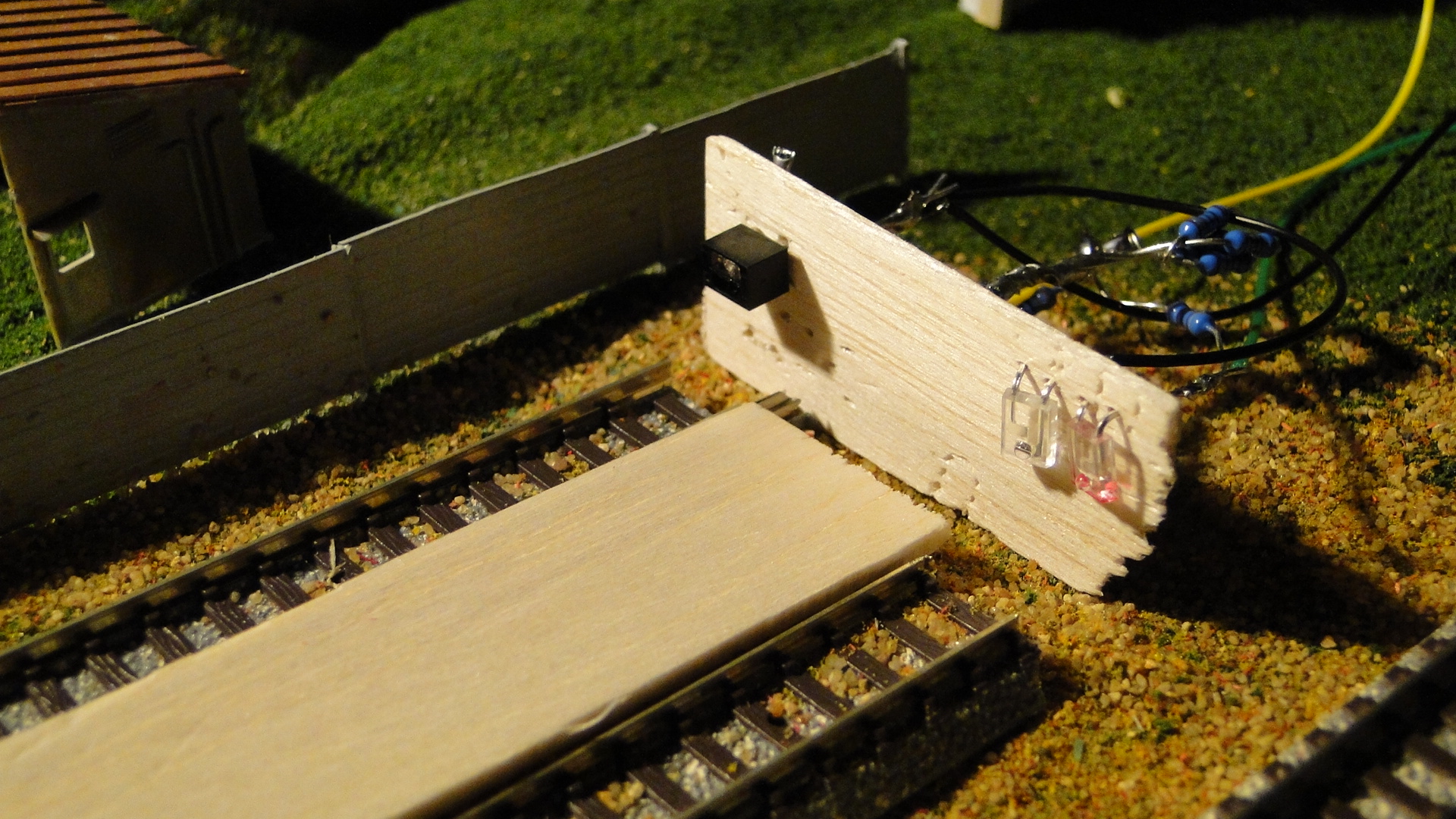
In this set up the emitter and detector are both facing towards an approaching vehicle. The emitter-side of the QRD1114 will always be emitting infrared light down the track. The detector will then receive the infrared light reflected off the vehicle as it approaches and its internal resistance will rise accordingly. This means we can read the resistance of the detector to know how close the train is therefore slow it down proportionately. We can therefore ensure the train does not hit the buffer by checking the value of the detector and altering the speed of the train quickly and appropriately.
Firstly, here's the circuit for wiring up both the 'Infrared Emitters and Detectors' and the Optical Detector / Phototransistor (recommended) from Toys Downunder. And Here's the datasheet for the latter QRD1114.
Note: I happened to test out both setups as I destroyed my first QRD1114 by applying 5v directly to the emitter... You must only apply 1.7v max!
And then the detector set up on the engine shed roads:
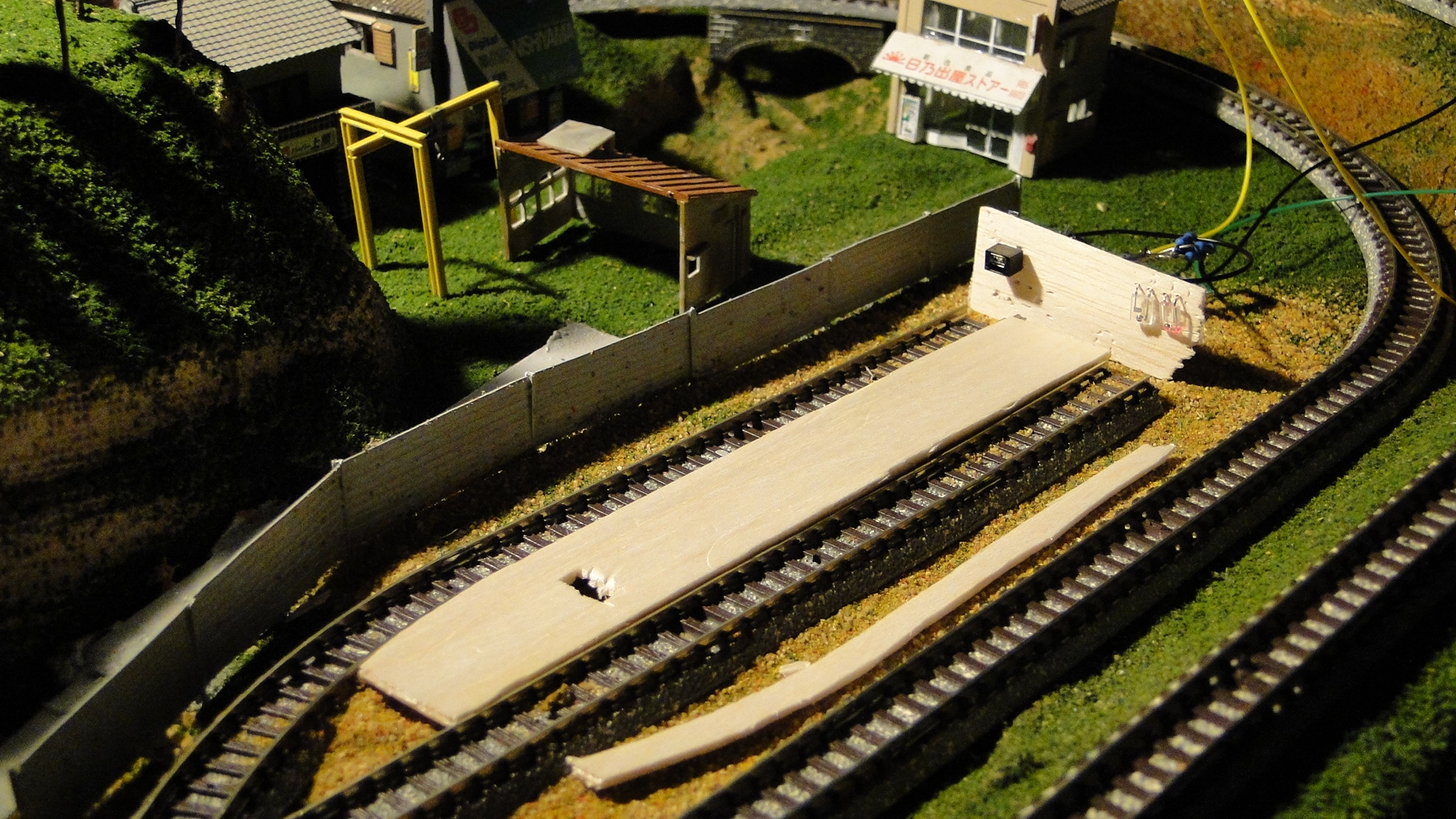
The two roads above will eventually be located inside an engine shed. Due to the potential interference from one emitter to the other, I will put a separator down the middle of the tracks.
The maxmimum read distance I could achieve was just under 6cm during testing**. This wasn't exactly what I was expecting and would've liked around 10-12cm for this purpose, but I worked around this. It seems that there is a more expensive detector at Toys Downunder: Sharp GP2Y0A21YK that can detect object up to 84cm away. I imagine it would be as simple as obtaining larger IR LEDs to boost the light output and therefore the light reflection.
Once the two detectors were in place, I set about automating a quick shunting process. I'd started noticing that, depending on room light, the readers weren't doing the best job; down to around 20mm distance was all that was being detected. This would not be enough to measure the speed as I wanted to, but I kept going anyway.
Programming the detector was the same as the potentiometer throttle done previously. The detector acted as a variable resistor and the reading would be from +1000 to 0 depending on the reflectivity of the object. It turned out that 0 was when the object was closest to the detector. Unfortunately, this only started changing once the object came within 30mm.
Here's a video of my quick shunt automation in action. First with the QRD1114 and then with the separate emitter/detector:
Results
I ended up stopping progress on this as the detector didn't respond as well as I'd have wanted. After getting a 6cm read distance during test I thought it would feasible, but this dropped to a max of 15mm when actually installed on the track. There would be too much re-adjusting to get either of the types of infrared detectors to work.
The only option from here is to purchase the Sharp detector mentioned above and see if it really can detect 84cm!
Random Photos
Creating a Japanese Torii (Shrine Entrance)
Photo Album Index
Search
Tags
Links - Click for details
- Abandoned Rails (Japan)
- AIRLINE (Shinkansen Photography)
- Akihabara Station
- annexpressのブログ
- Australian Model Railway Magazine
- DCC普及協会ホームページ (Japanese DCC)
- Dead Section (Japanese Track Diagrams)
- Delicious Things (Japanese N Scale DCC)
- Densha Wotorou
- Digital Direct for Windows (DCC Server)
- Don's Dream World – AMAZING N Scale Japanese Layout
- Hatena::Diary
- Japanese N-Scale Modeling Forum
- JR Chiisai
- Kaz-T's blog レインボーライン (Rainbow Line)
- LED Resitance Calculator
- Masioka
- Poppondetta Blog
- RailFan Magazine, Japan
- Railmind
- Railway Travelers' Room
- Serenity Valley
- Shashinka Ichiban
- Shuzuku
- Sumida Crossing
- The next station is…
- Tomix N Gauge Track and Japanese N Gauge Trains
- TT Forums (Transport Tycoon Deluxe)
- 名鉄尾西線の貨物列車 (Nagoya: Meitetsu Freight)
- 日本型Nゲージ DCC改造例のご紹介 (Okiraku DCC)
- 泰 茅 轍 道 (Taichi Railway)
- 箱庭登山鉄道製作記 (Hakone-Tozan Layout Blog)
Archive
- July 2026
- May 2026
- April 2026
- March 2026
- February 2026
- January 2026
- November 2025
- October 2025
- September 2025
- August 2025
- July 2025
- June 2025
- February 2025
- January 2025
- November 2024
- September 2024
- August 2024
- July 2024
- June 2024
- May 2024
- April 2024
- March 2024
- February 2024
- December 2023
- October 2023
- September 2023
- August 2023
- July 2023
- June 2023
- May 2023
- April 2023
- March 2023
- December 2022
- November 2022
- October 2022
- April 2022
- March 2022
- February 2022
- January 2022
- December 2021
- November 2021
- September 2021
- August 2021
- July 2021
- May 2021
- March 2021
- February 2021
- January 2021
- October 2020
- September 2020
- August 2020
- July 2020
- June 2020
- May 2020
- April 2020
- March 2020
- January 2020
- December 2019
- November 2019
- October 2019
- September 2019
- August 2019
- July 2019
- June 2019
- April 2019
- March 2019
- February 2019
- January 2019
- December 2018
- November 2018
- October 2018
- September 2018
- August 2018
- July 2018
- June 2018
- May 2018
- April 2018
- March 2018
- January 2018
- December 2017
- November 2017
- October 2017
- September 2017
- August 2017
- July 2017
- June 2017
- May 2017
- March 2017
- February 2017
- January 2017
- December 2016
- November 2016
- October 2016
- September 2016
- August 2016
- July 2016
- June 2016
- May 2016
- February 2016
- November 2015
- October 2015
- September 2015
- August 2015
- July 2015
- June 2015
- May 2015
- April 2015
- March 2015
- February 2015
- January 2015
- December 2014
- November 2014
- August 2014
- July 2014
- May 2014
- April 2014
- March 2014
- December 2013
- November 2013
- October 2013
- June 2013
- August 2012
- April 2012
- March 2012
- February 2012
- November 2011
- October 2011
- September 2011
- July 2011
- June 2011
- May 2011
- April 2011
- March 2011
- February 2011
- January 2011
- December 2010
- November 2010
- October 2010
- September 2010
- August 2010
- June 2010
- May 2010
- April 2010
- March 2010
- February 2010
- January 2010
- December 2009
- November 2009
- October 2009
- August 2009
- January 2009
- December 2008
- November 2008
- October 2008
- September 2008
- July 2008
February 25th, 2010 - 12:57
It’s in an ODFN package, which should rightly give you the shivers (although I bet there’s a SchmartBoard for it), but I have a couple of these and they look really promising:
http://www.silabs.com/Support%20Documents/TechnicalDocs/Si1120.pdf
Or these?
http://www.sparkfun.com/commerce/product_info.php?products_id=242
February 25th, 2010 - 13:03
That first Si1120 looks interesting, but not too easy to find.
Otherwise the Sharp is the model I mentioned in the post. I’m just concerned of it’s size and it is a lot more expensive. I’ll give this another go in due course, with those Sharp detectors… Better things to attempt next :)
February 26th, 2010 - 02:03
I have two of the Si1120 that I’d be happy to send to you to try out. I thought they were SSOP packages, which I am comfortable soldering, but they weren’t. They were free samples, so it’s no problem for me if you think you’d like to try them. You do have to build an enclosure for them though, is the rough part. And be comfortable soldering them. Email me if you’re interested.
June 20th, 2015 - 19:03
I’m using TCRT5000, which are combined emitter and receiver, and so far working well and have adjustable sensitivity on uk ebay at £0.99
http://www.ebay.co.uk/itm/Infrared-IR-Reflect-Photoelectric-Switch-Barrier-Line-Track-Sensor-TCRT5000-HC-/281648170253?pt=LH_DefaultDomain_3&hash=item41938a050d
August 7th, 2015 - 17:04
These little IR sensors (I’ve mainly used the TCRT5000) are designed for detecting close things primarily. If you read the datasheet for the TCRT5000, it works best at 2mm!
While I’m yet to try the QRD1114, with the TCRT5000’s we’ve used, you need to do two things.
The first is to give the IR LED its maximum rated current. We ran these at 20mA, and at 60mA. At 20 mA they kind of worked on the bench within about 20 millimetres. At 60mA they’d work on the bench out to about 150mm. You can’t pull 60mA out an Arduino port. Use the arduino to drive a transistor (2N3904), which powers the IR LED.
The 2nd thing is to “flash” the IR LED, and take a reading both IR illuminated, and with only ambient illumination. Reading the IR sensor both times, you can take a delta. This is your “real” reading.
On our circuit it did take a couple of milliseconds (~10) for the IR light to “power up”. So we’d power up the LED, wait 10 milliseconds, read, power-down, wait 10 milliseconds, read again. We didn’t tune this though, maybe 3ms is enough. *shrug*.
I was thinking you could also embed them in the track, maybe “beaming” up between rails. yeah, that might work. Hmmm, dust might be a problem.
August 7th, 2015 - 17:19
Kingsley,
This information is invaluable for anyone wanting to implement what I really only lightly touched on. Your idea of sampling the values of light when on and off is perfect, as it’ll let you work out the ambiance… as long as the ambiance doesn’t change.
Do report back if shining from between the tracks works. I assume it would work fine, as long as the surrounding area was dark. You’d be monitoring the reflection of the vehicle chassis’ as they pass and any light shining down into the sensor would disrupt that.
Thanks for the input!