


 Melbourne BG SCS Train Timetable


Lighting a Japanese Temple
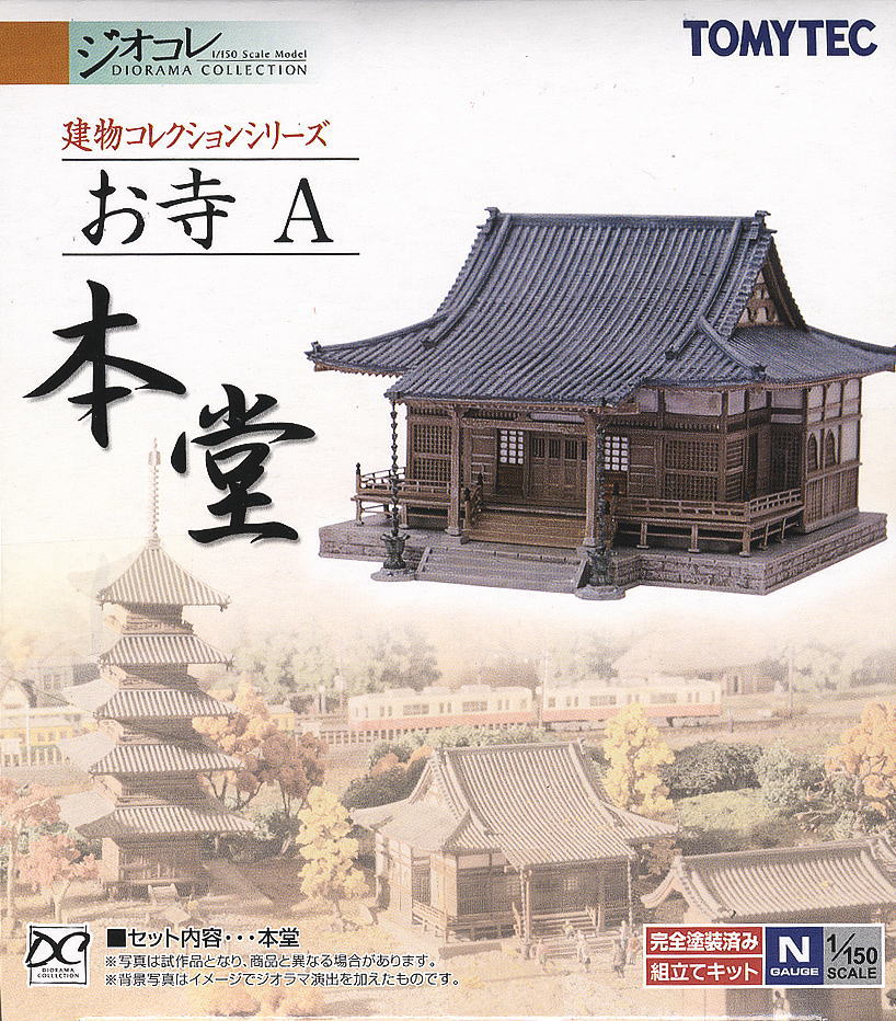
I'd decided it was time to light the temple after building the Torii for the entrance. This temple was the Tomytec Japanese Temple A (Main Building) and is still available for purchase from most Japanese online hobby retailers.
I've slapped LEDs in buildings before, but this time I also wanted to add lanterns to the front of the shop. I'd made the lanterns before, as in my previous attempts of creating the Torii, but I was to make a few changes this time as I wasn't totally impressed with the previous outcome.
Creating the lanterns
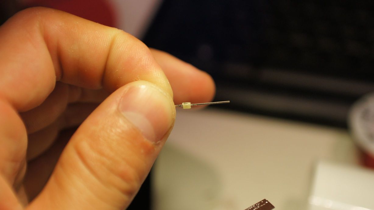
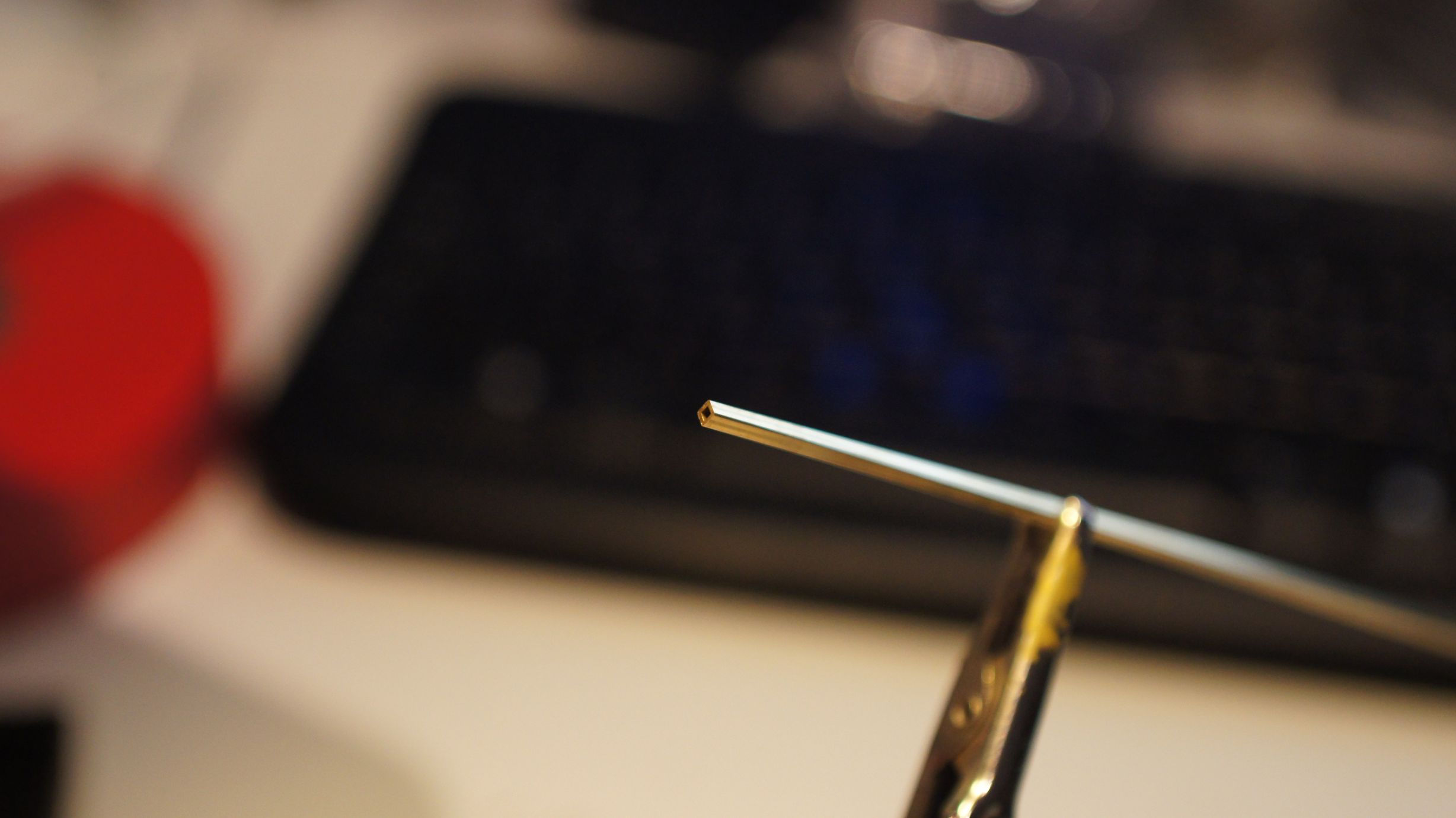
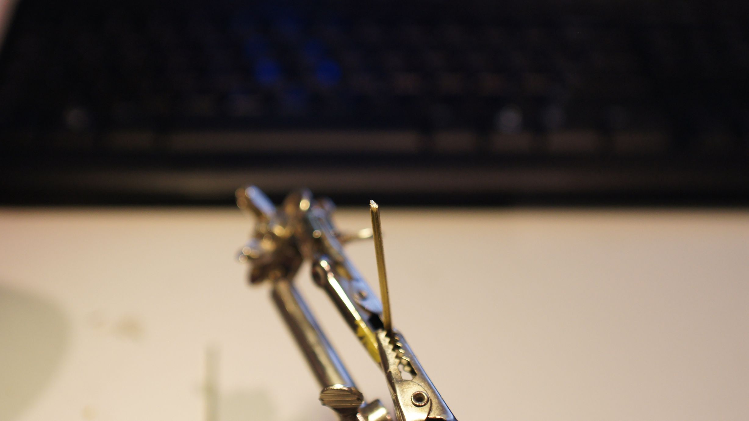
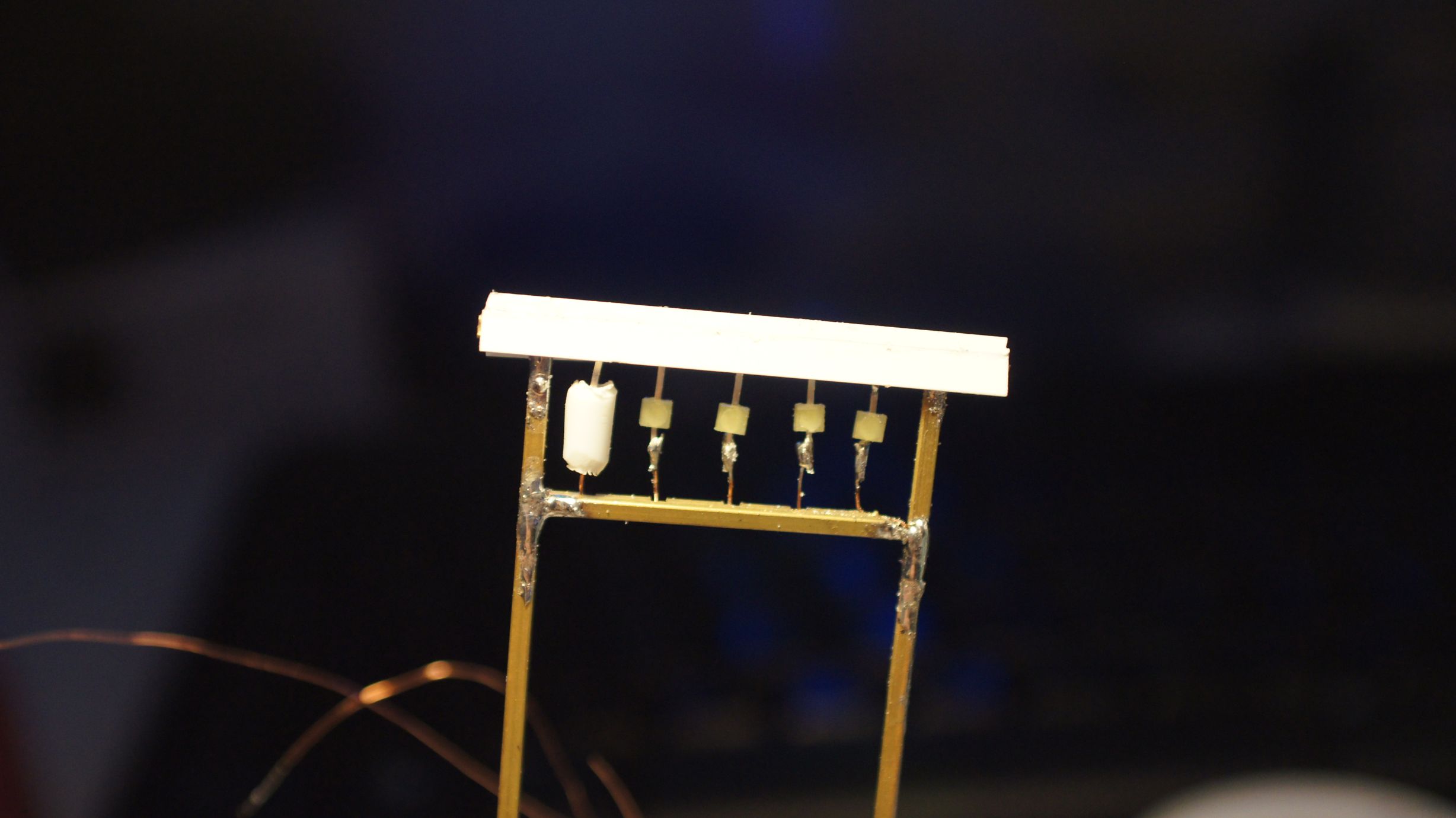
There was a slight change this time to creating the lanterns... instead of cutting them and sliding them over the LEDs, I shaved them down to fit and inserted them into the center of the tubing. This all worked well, but you must be careful when shaving down the LEDs as you can destroy them quite easily. To shave the LEDs, I held them in pliers in one hand and filed away with my pocket knife. It was pretty obvious to feel when you were no longer filing away at plastic and, unfortunately, this was usually the demise of the LED.
Mounting the lanterns
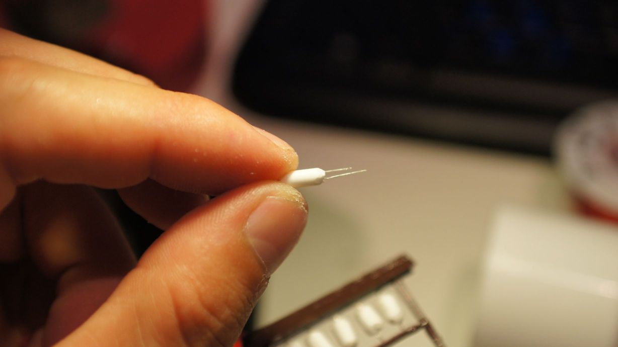
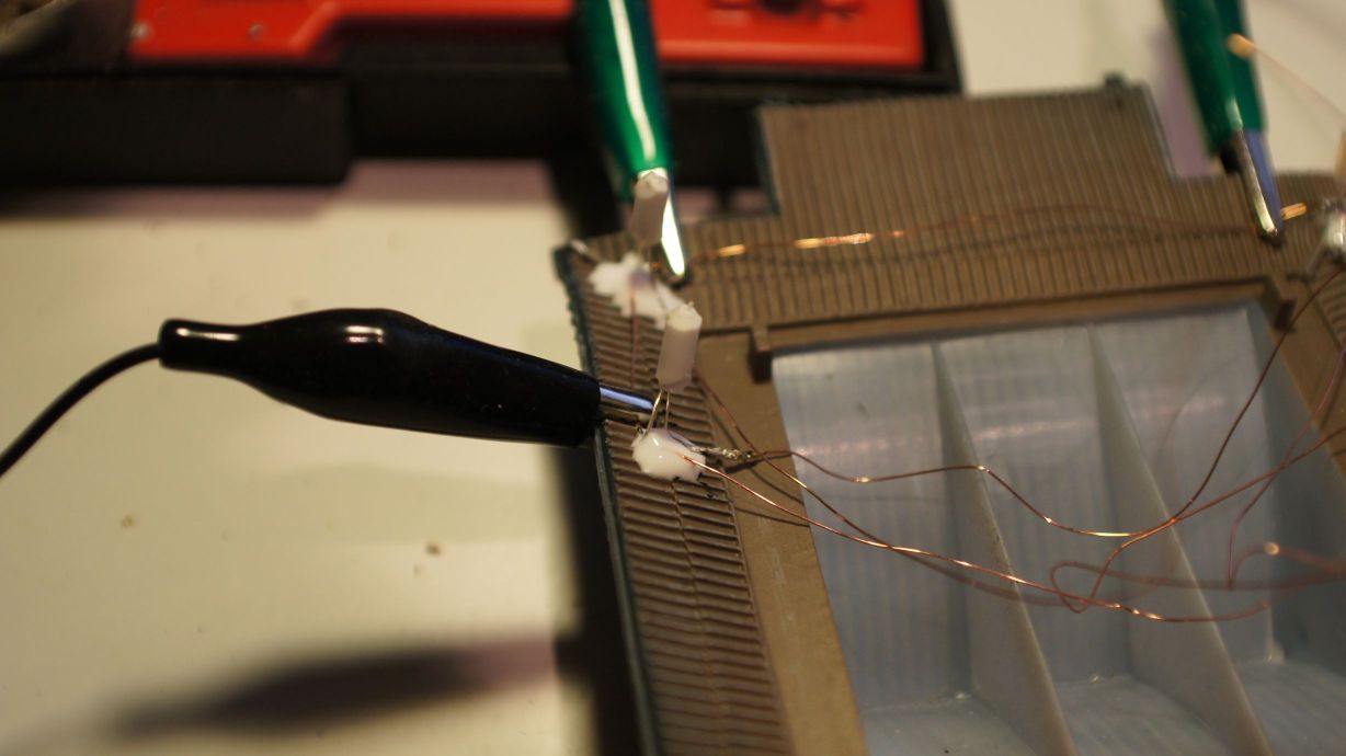
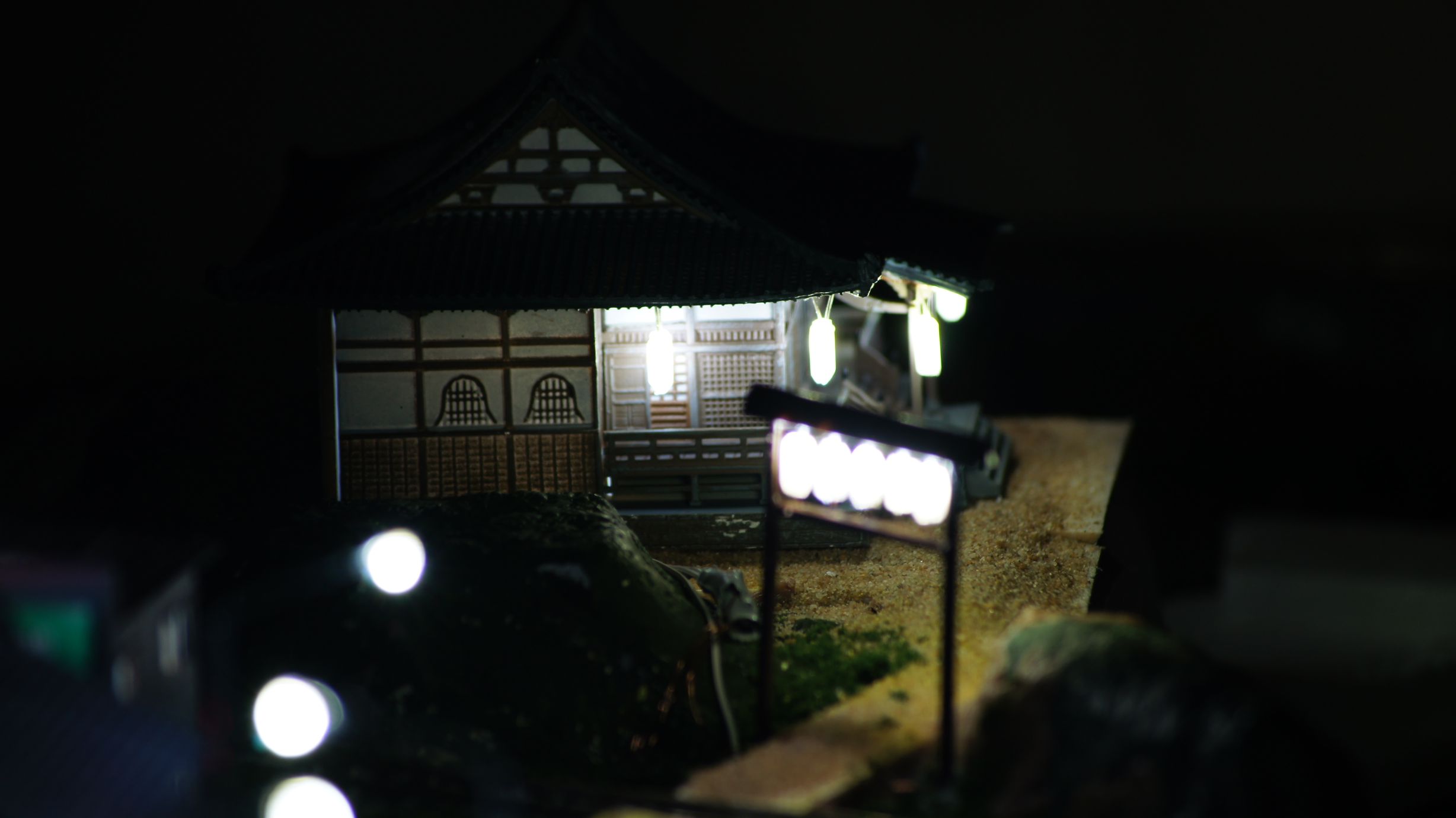
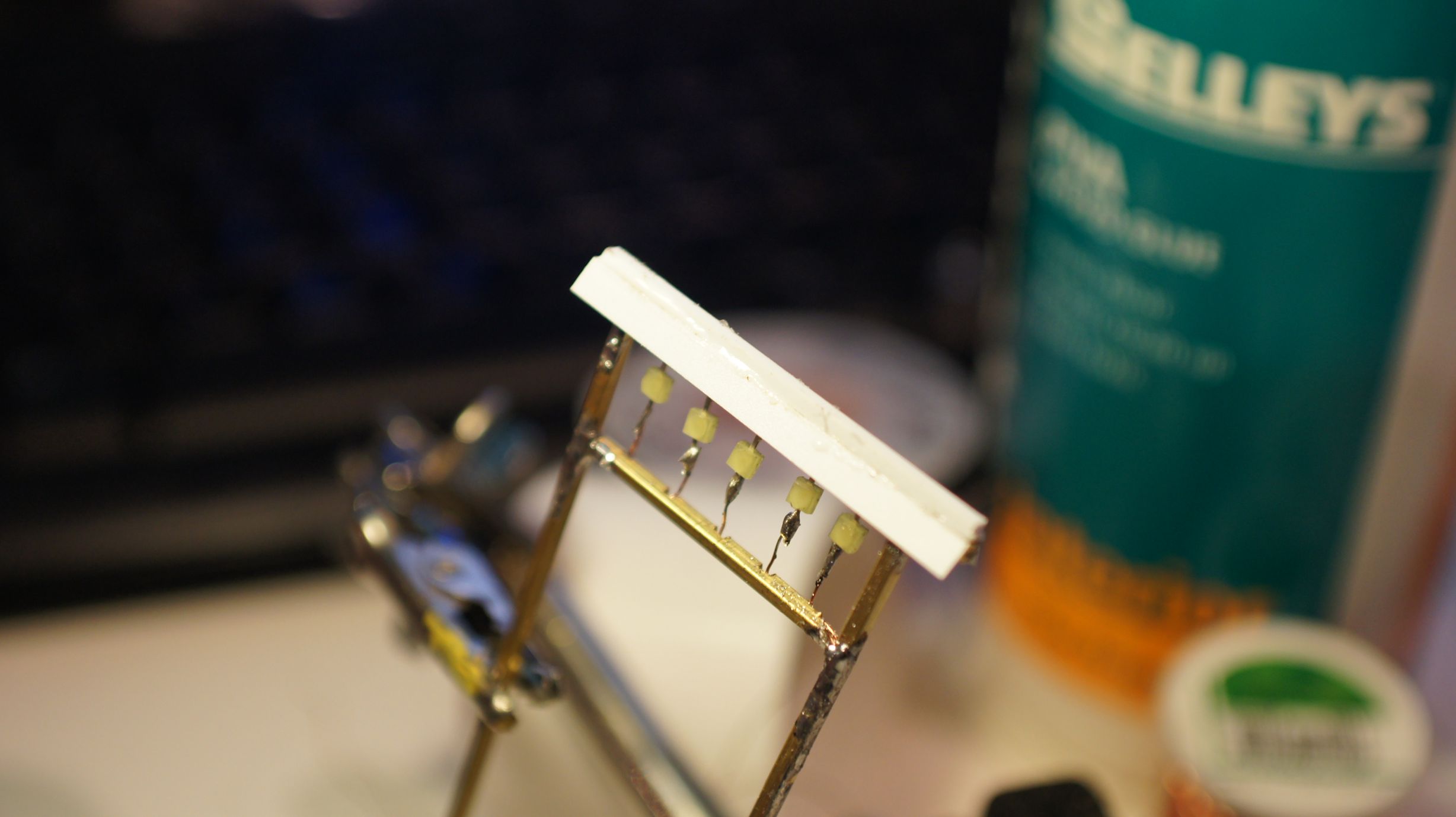
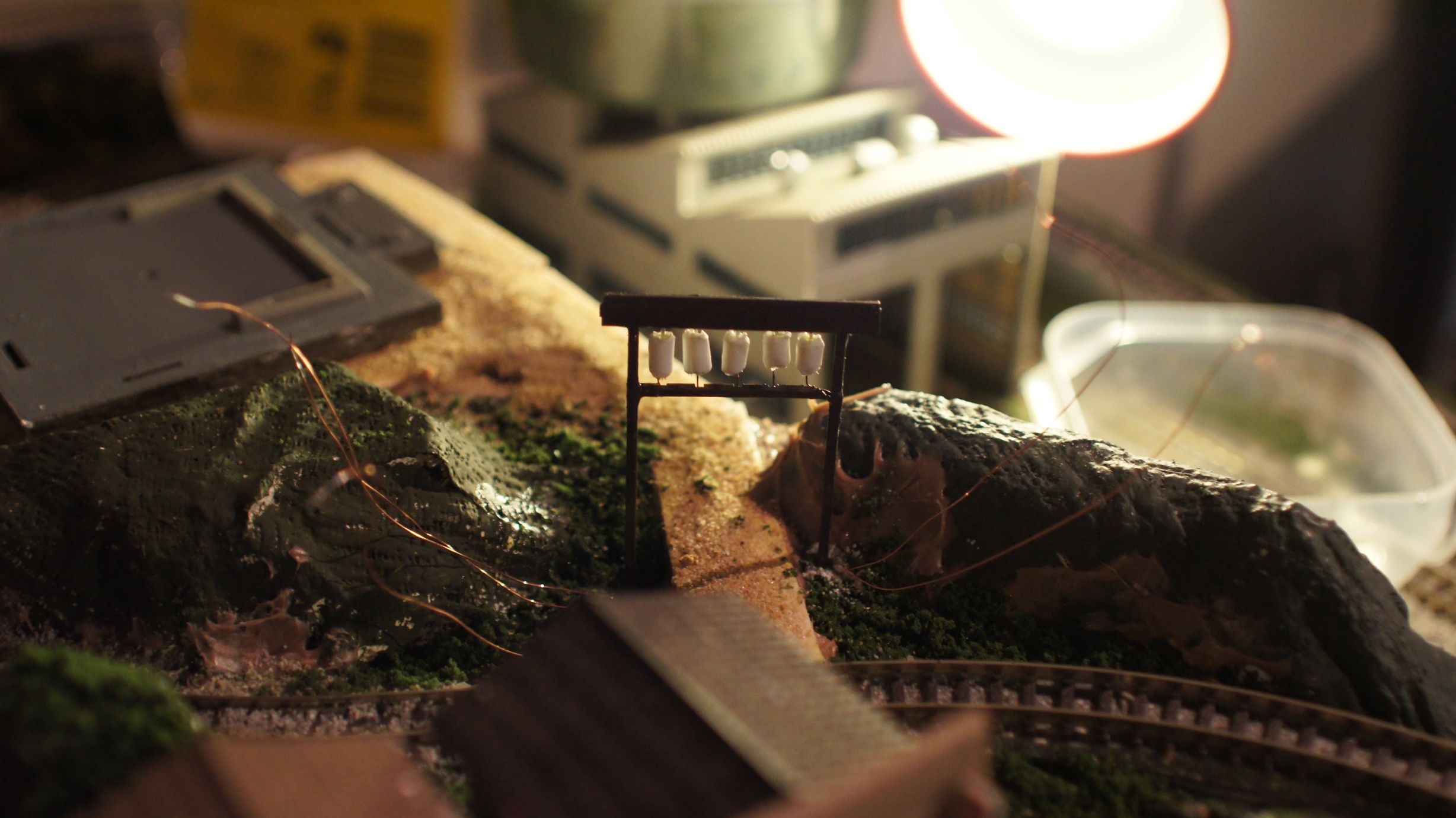
I used the same copper winding wire that I always do and bent it into a rectangular shape to fit the roof of the temple. I then started soldering the lanterns in place.
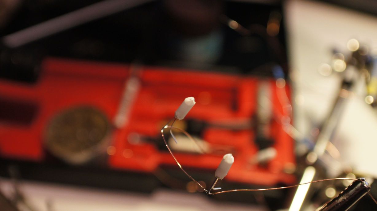
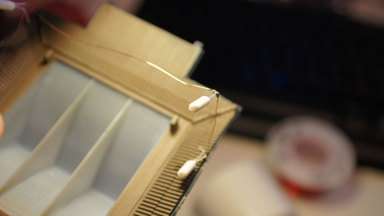
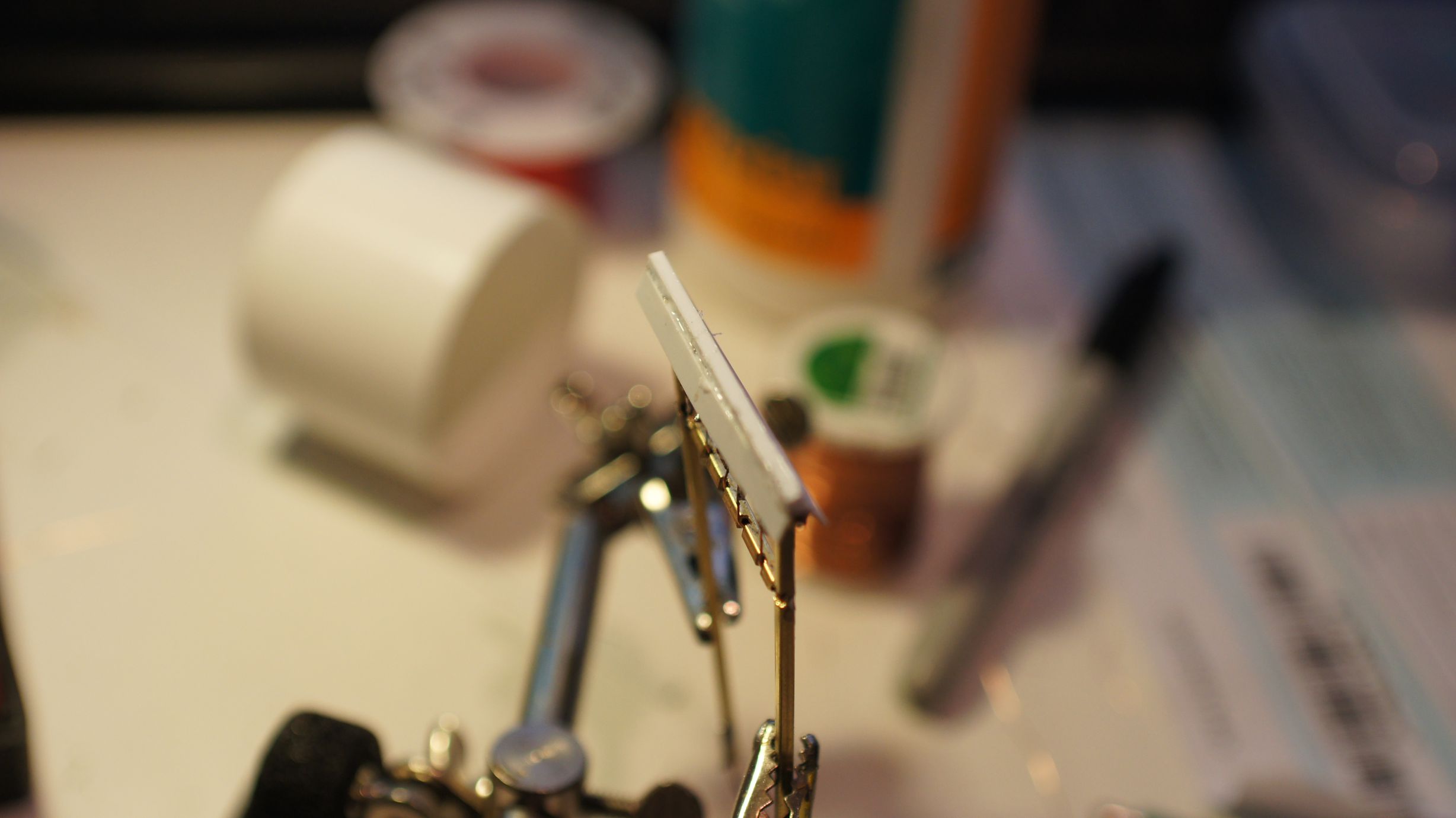
I then pulled out the trusty Selleys Aquadere and, using random aligator clips found on the bench, glued the lanterns in place.
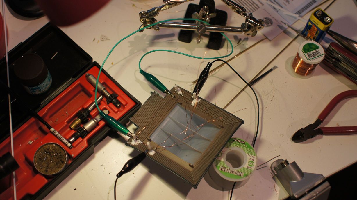
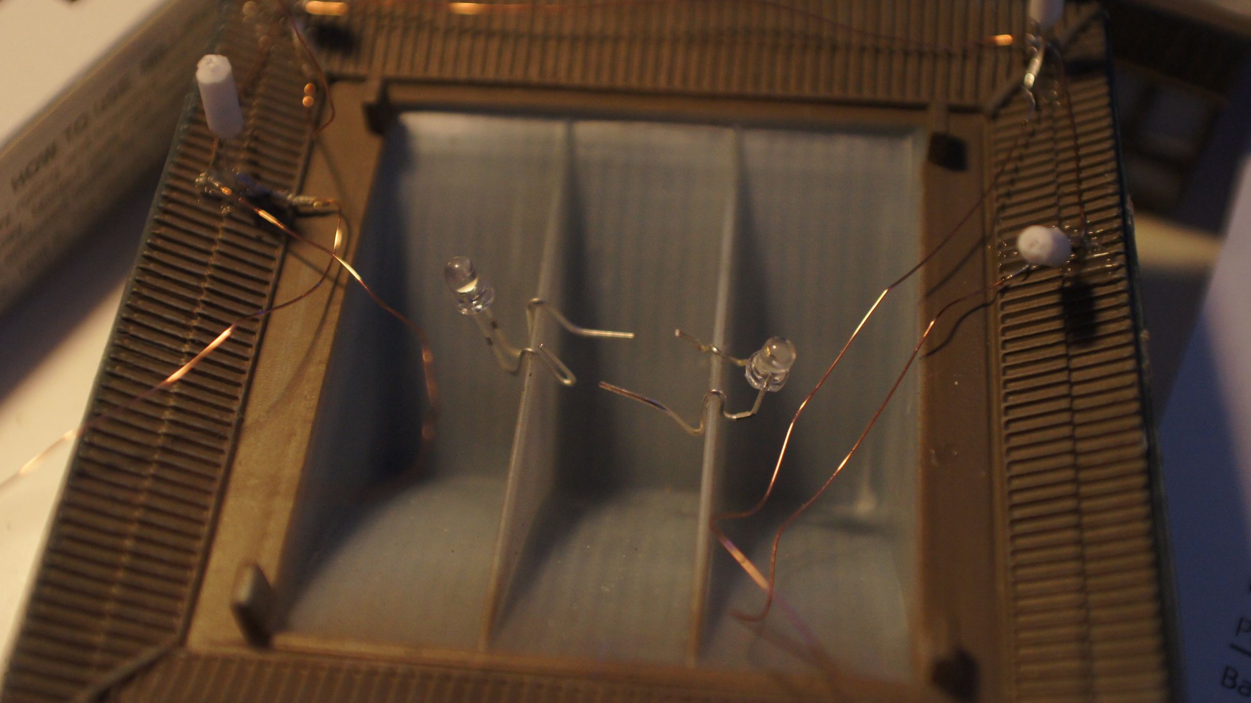
I also put two standard 3mm white LEDs in the center of the ceiling for building lights.
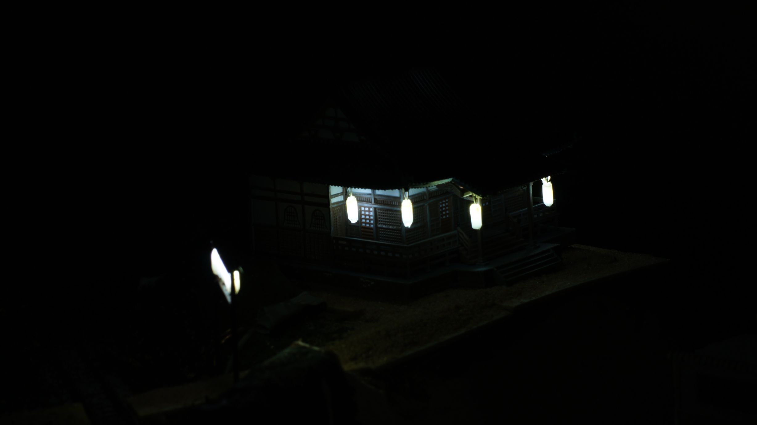
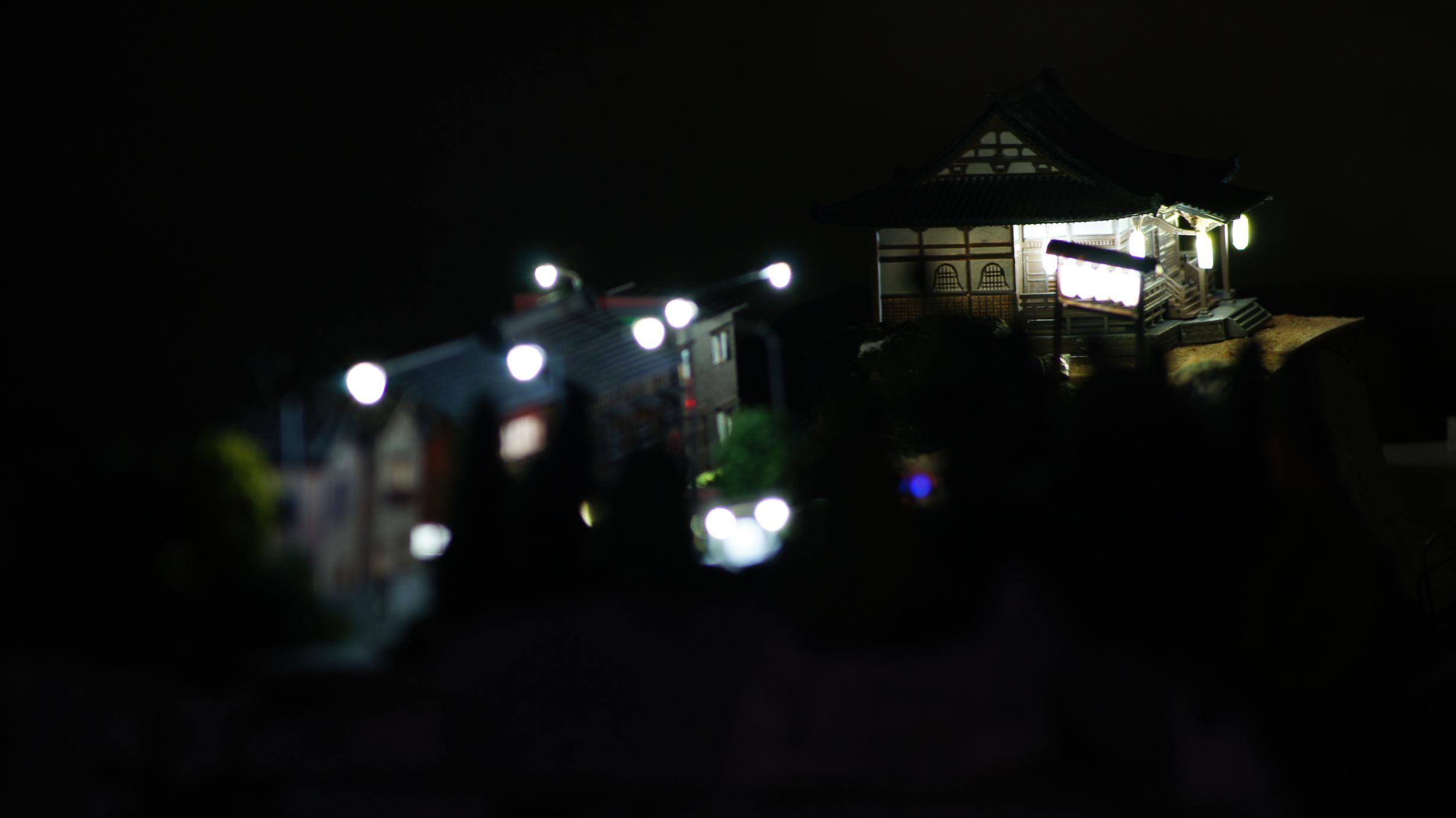
The finished product
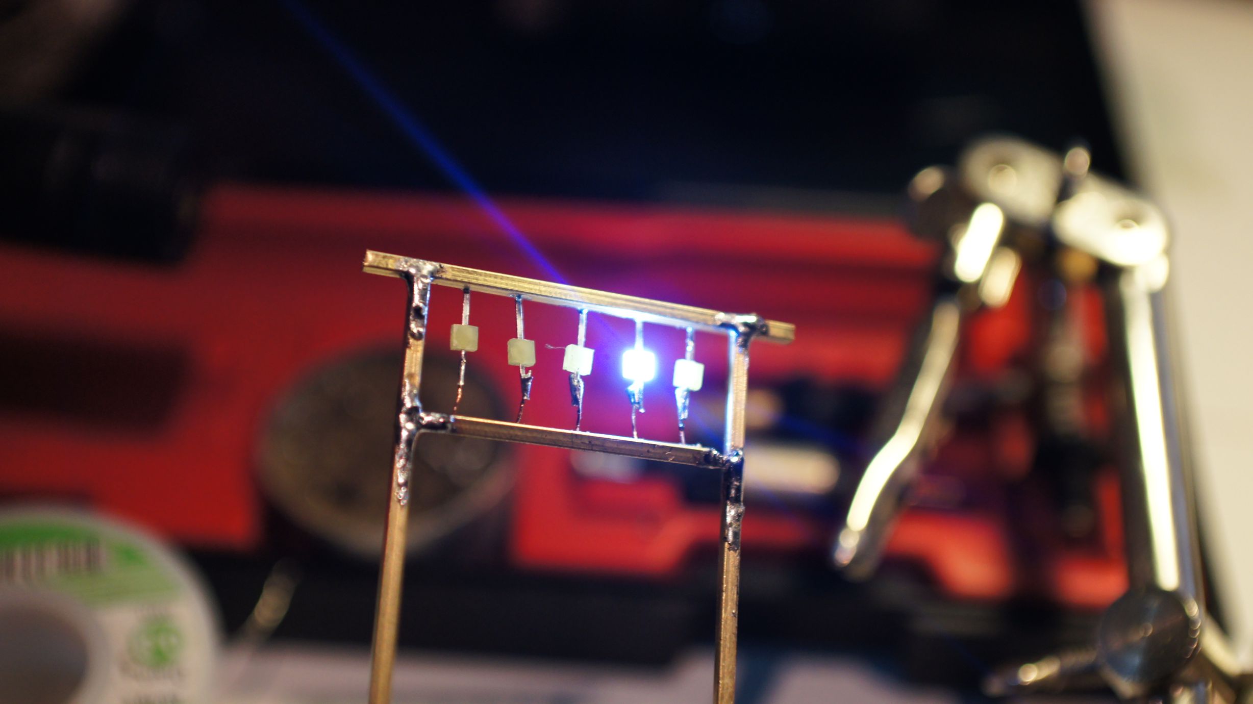
After the glue had dried, I tested all the LEDs and found that I'd broken the front-left lantern. This was 24hours after starting the project and frustrating. I quickly removed it from the temple and filed another LED down. I left it dry again, overnight, after testing, gluing and testing again.
Finally, yesterday, I was able to hook it up to my Arduino LED Controller. It worked perfectly and I took the opportunity to test my night-time photography skills.
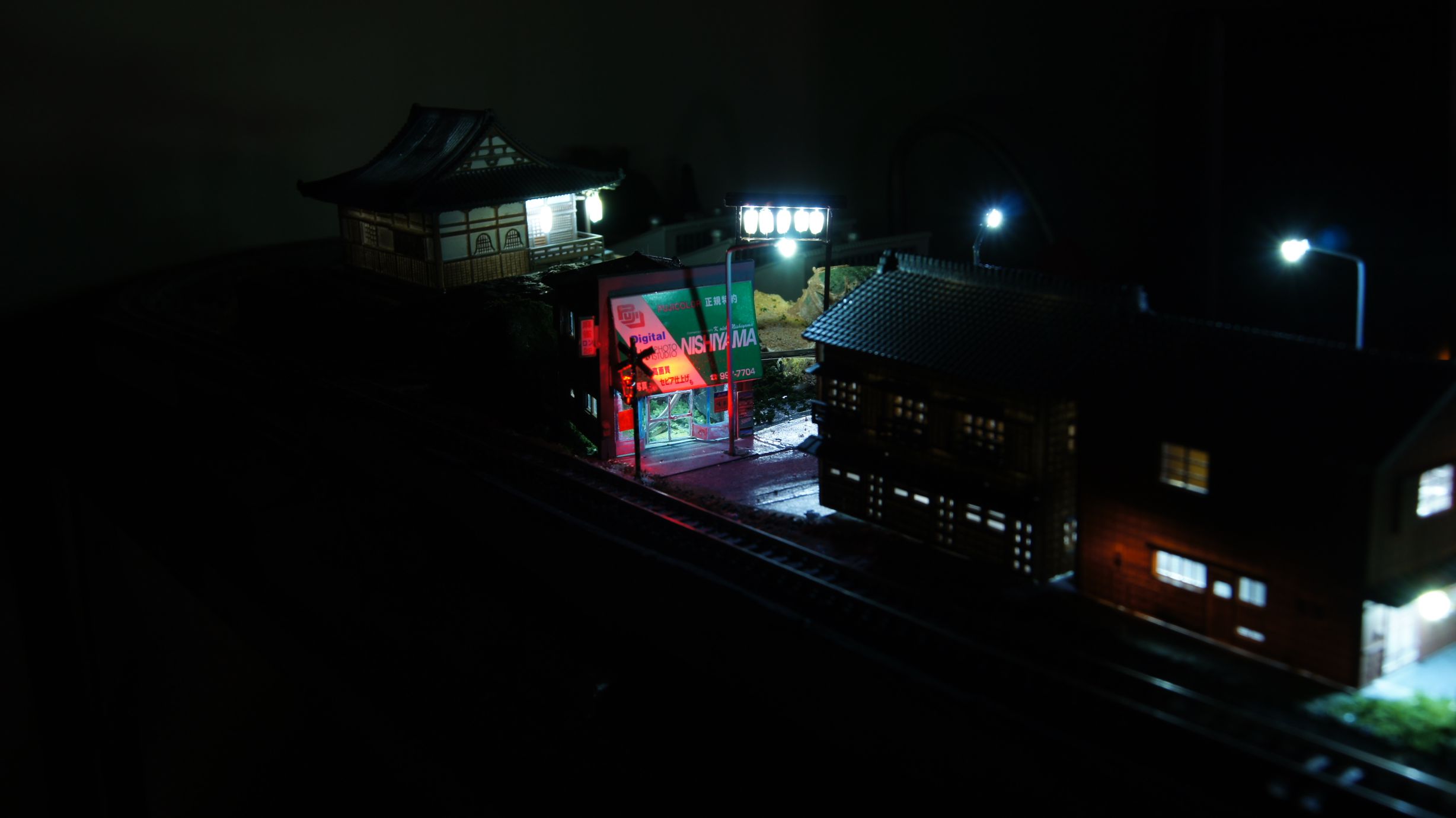
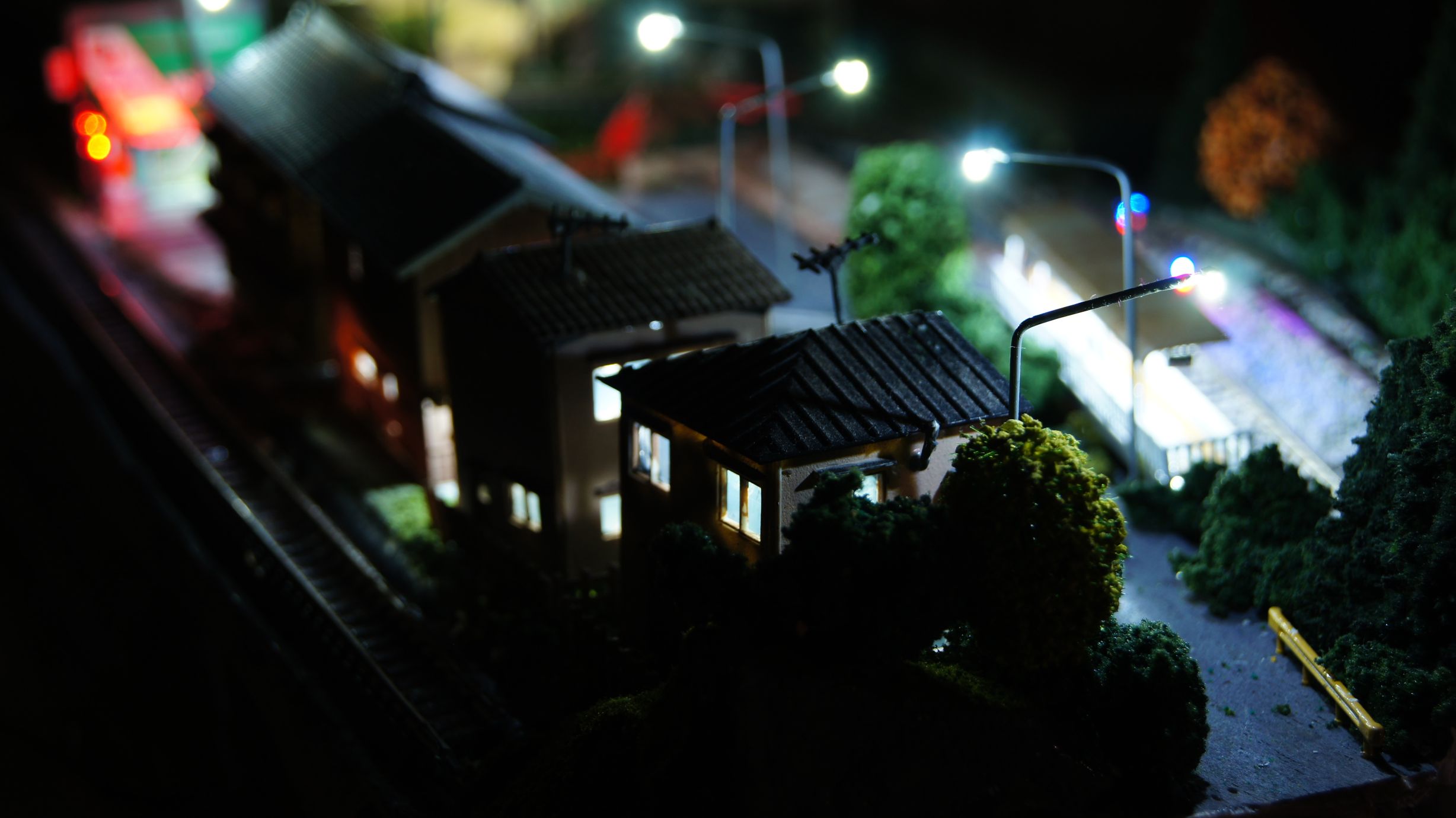
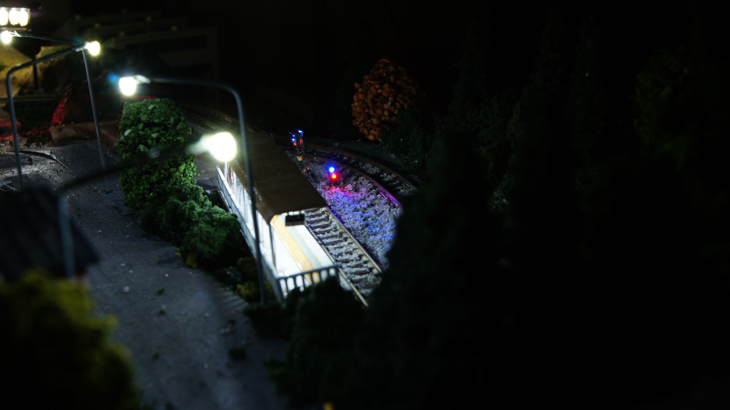
Now to settle the landscape around it.
Creating a Shrine Torii Entrance
After checking out more of the work by tanaka_ace on the Tounosawa Blog, I've decided to add a Japanese Shrine to my layout. I've extended the upper level to allow room for a kit I bought in Japan last September and have created a path back to the main town area.
As with any Shrine in Japan, the grounds are seen as sacred and insulated from the surrounding area; usually by either high walls or thick vegetation with a Torii gate for the entrance. I'll be adding the walls in soon enough, but prior to doing so I wanted to make sure I had all of the buildings and scenery effects in place.
The first thing to create was the Torii gate entrance. Tanaka_ace on his Tounosawa Blog had created a very nice gate with LED lanterns added. This is all based off a real-life location at the Tounosawa Station on the Hakone Tozan Railway. He had also created a blog post showing what he based the model off.
My version
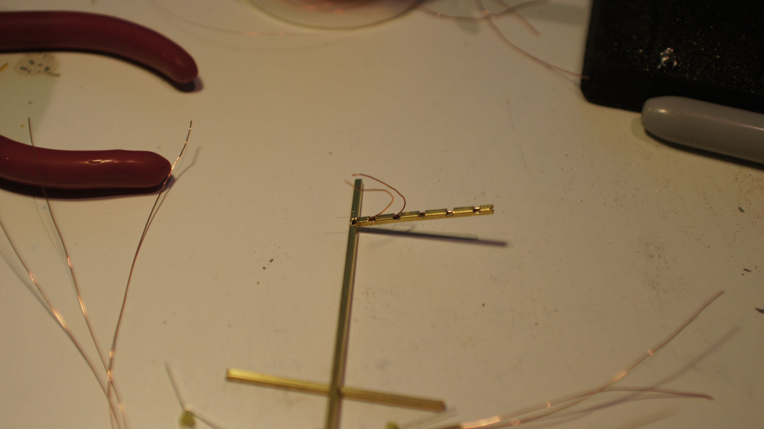
I've used the same gauge winding wire I'd used for my level crossing lights, streetlights and building lighting. With this I've also used 1/16" brass pole for the main frame of the gate because I wanted to emulate wood rather than a cylindrical concrete post this time. This also provided a little more room to squeeze the wires through. Each length needed to be cut down to size and then filed back. I used standard snips to cut the brass, a smaller saw would've been a better idea.
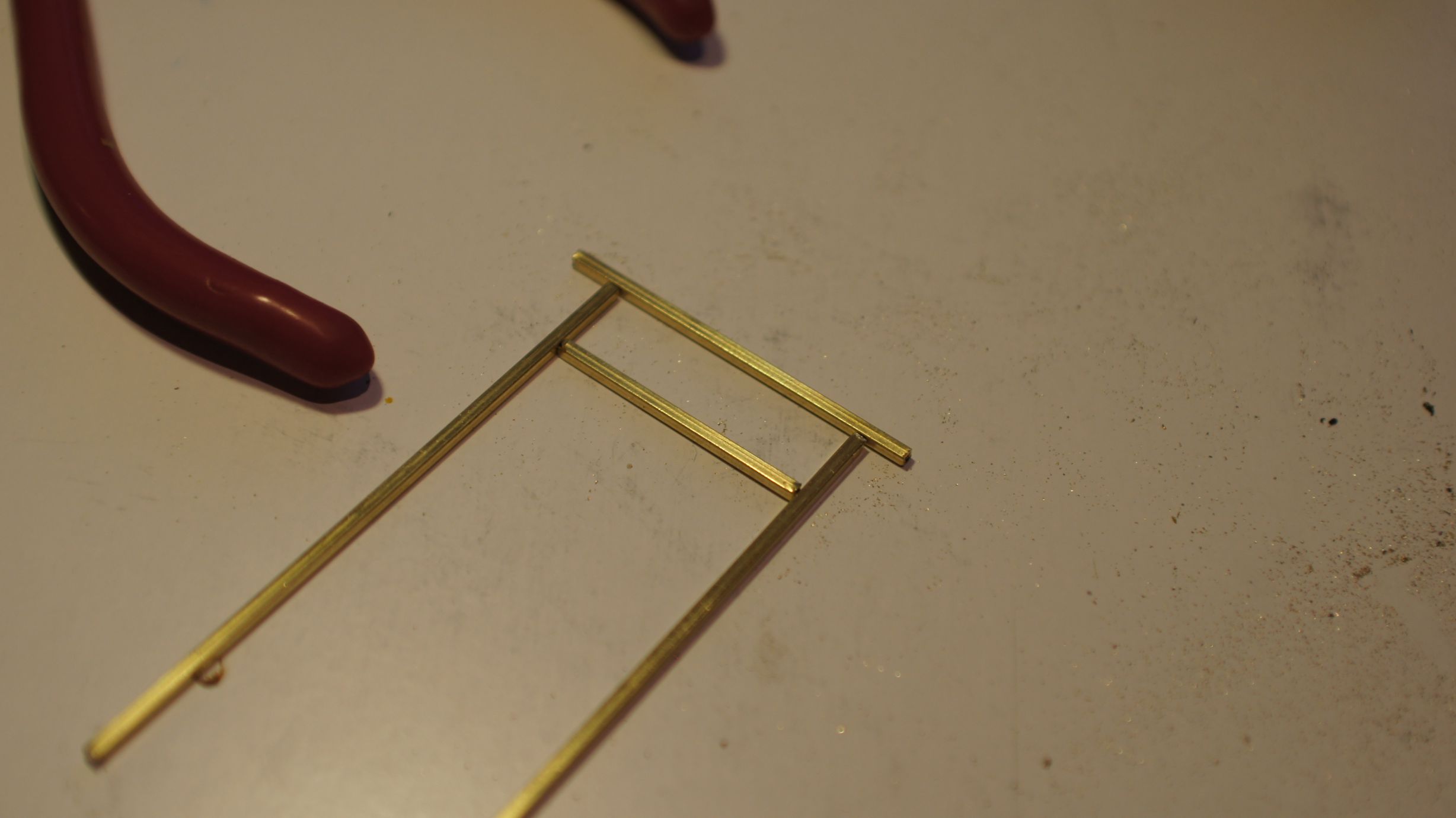
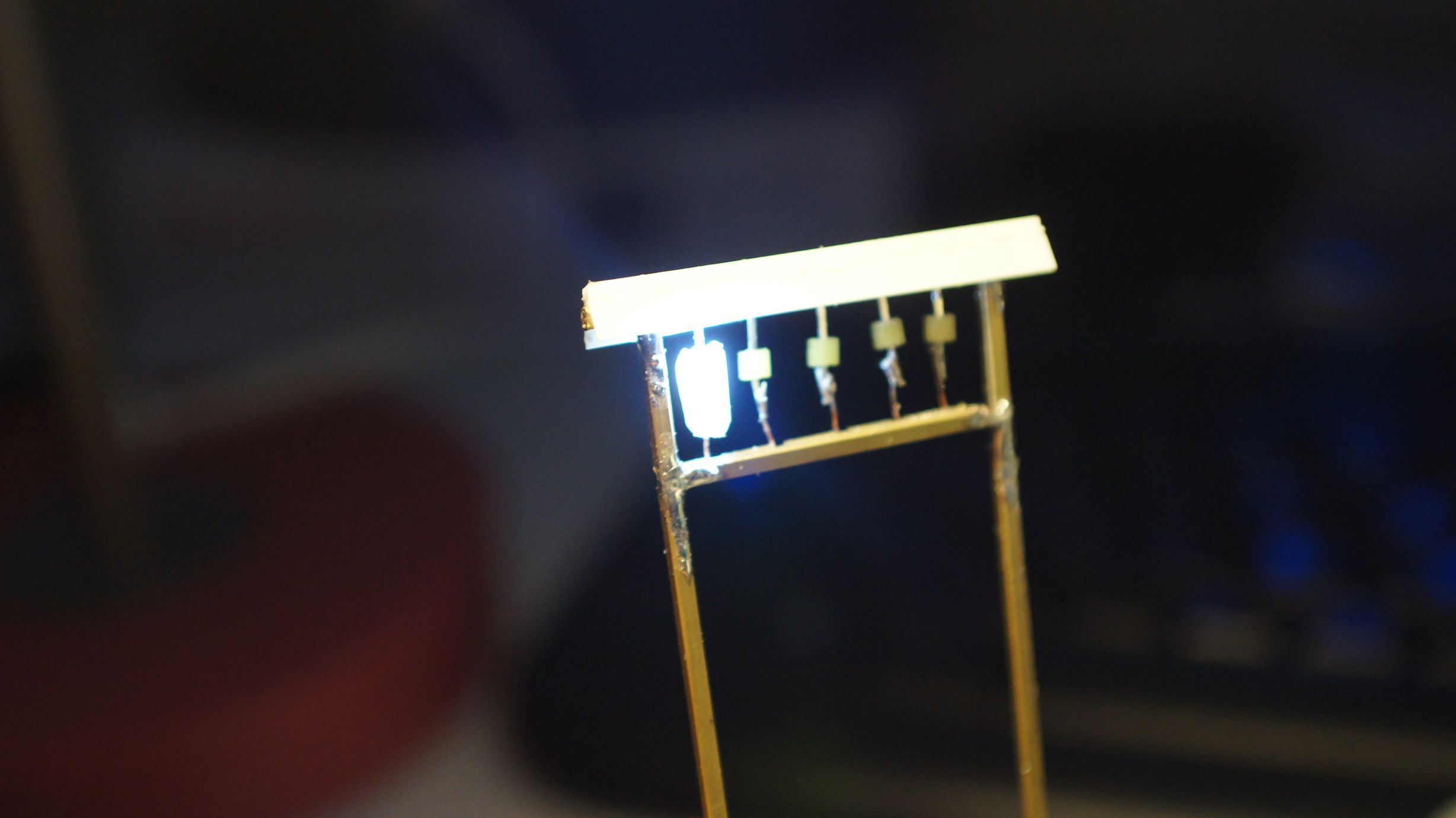
I based the size on the path that I had already created on the layout. I didn't really have a real-life prototype to work off and made a lot of it up as I went. The final size was around 50mm wide and I could fit 5 lanterns in. Below you can see the framing taking place.
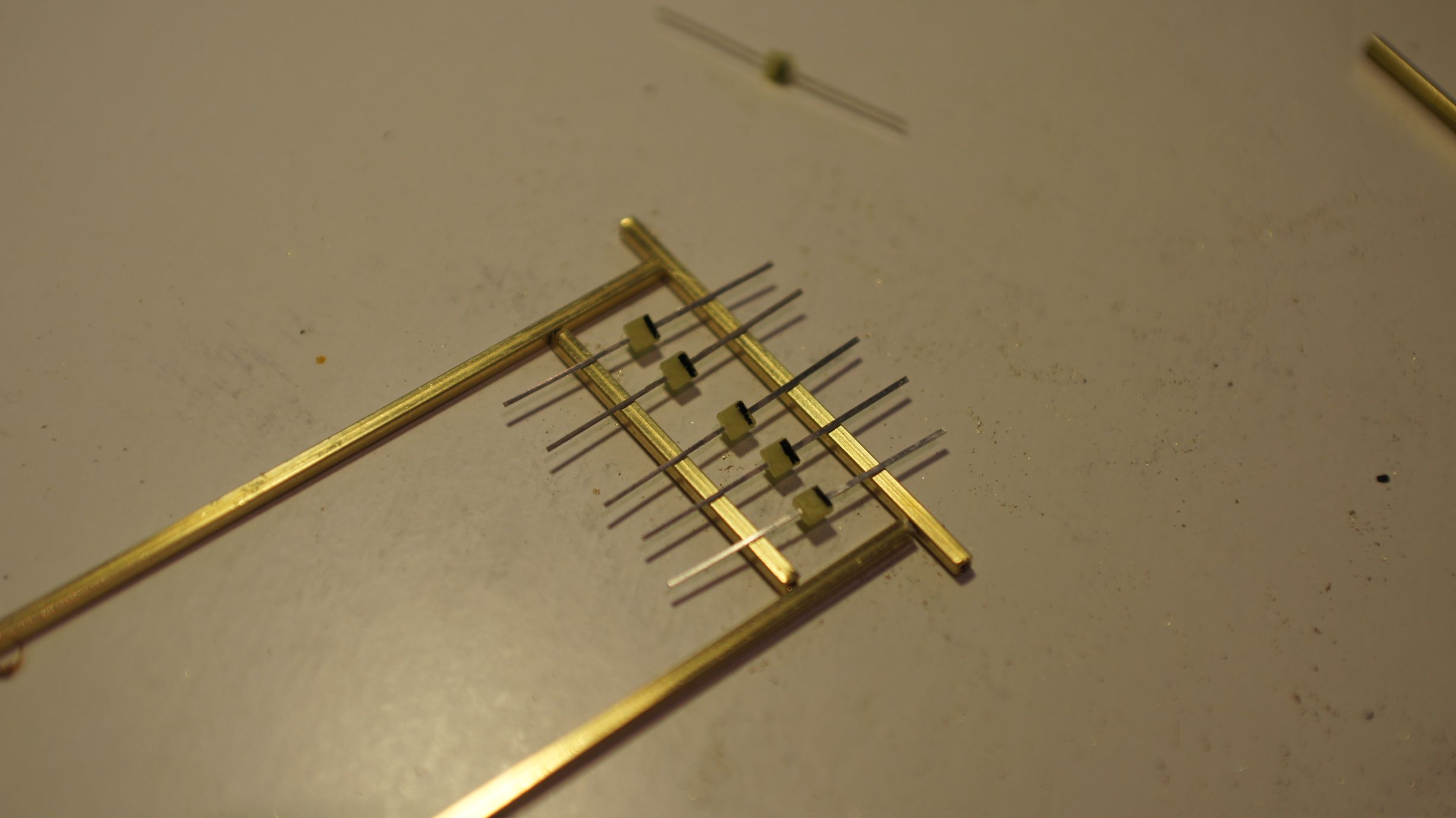
I then started cutting out the holes to feed the wire through. I used my trusty pocket-knife as the brass was quite soft. I also used a wire cut off a resistor to clean out the tubes of any metal shavings. The entrances created for the wires would have sharp edges and could scrape off the insulation on the wires, so I made the holes as big as possible.
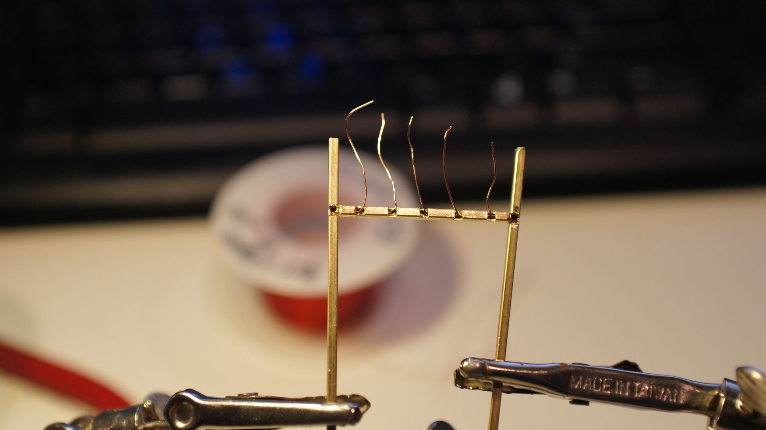
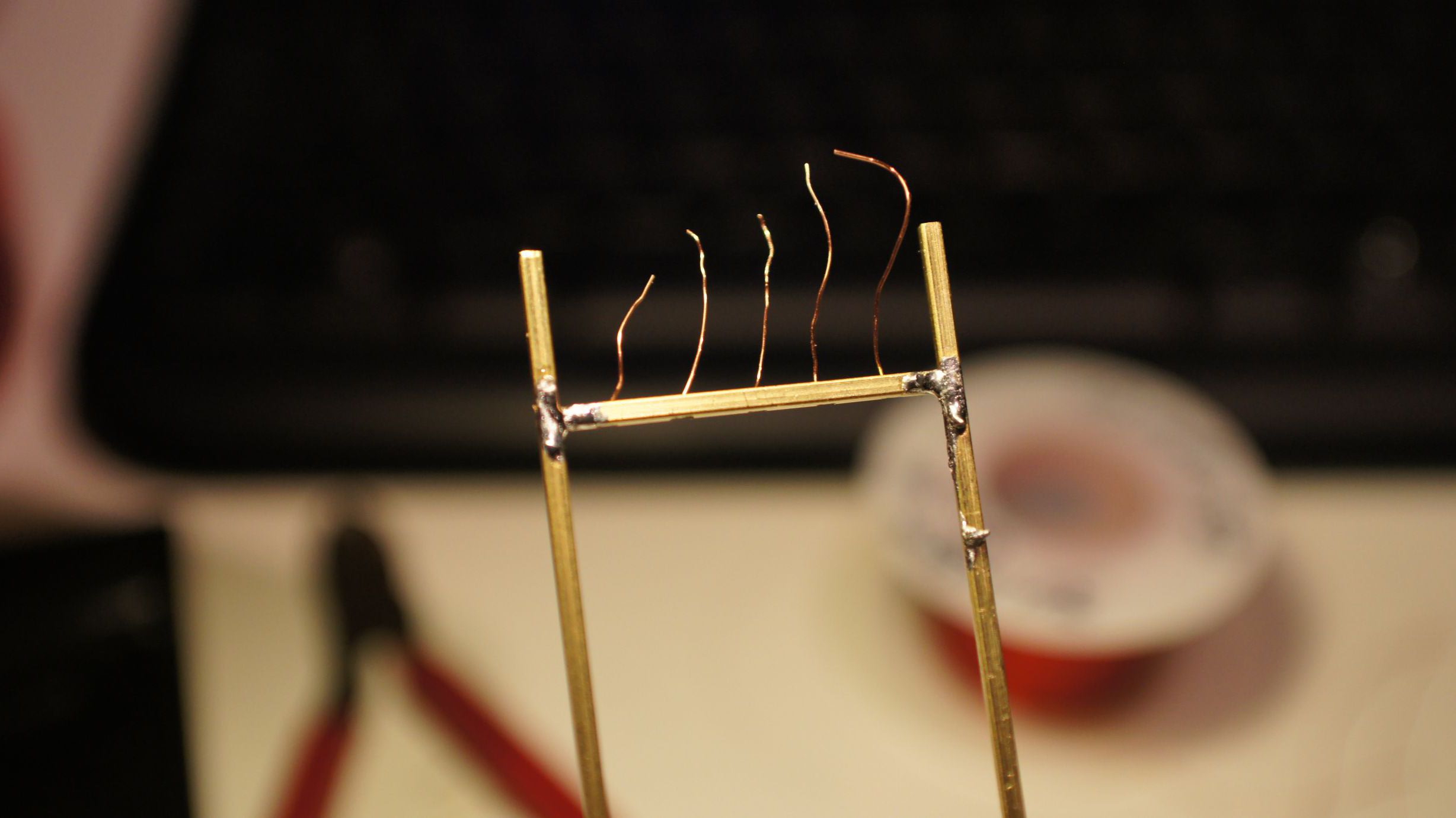
Once the holes were cut, I fed the wires through as a test. I then constructed the frame with solder. At this point I accidently overheated the wires on the left side. This caused one to ground and I then couldn't successfully light 1 of the 5 LEDs. I took more care the second time around when soldering the frame back together.
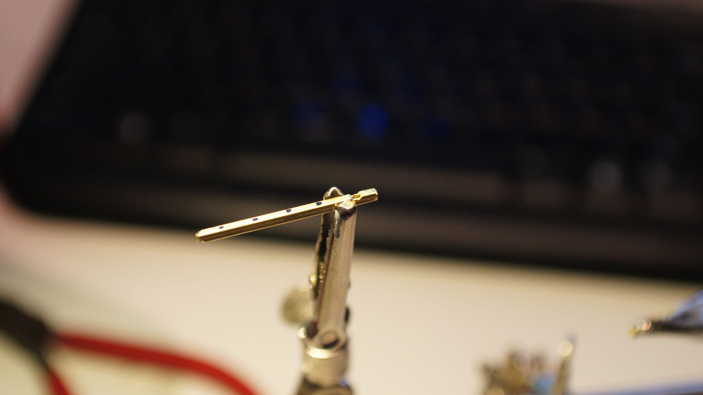
I added a quick roof to the frame as tanaka_ace had done with his second version.
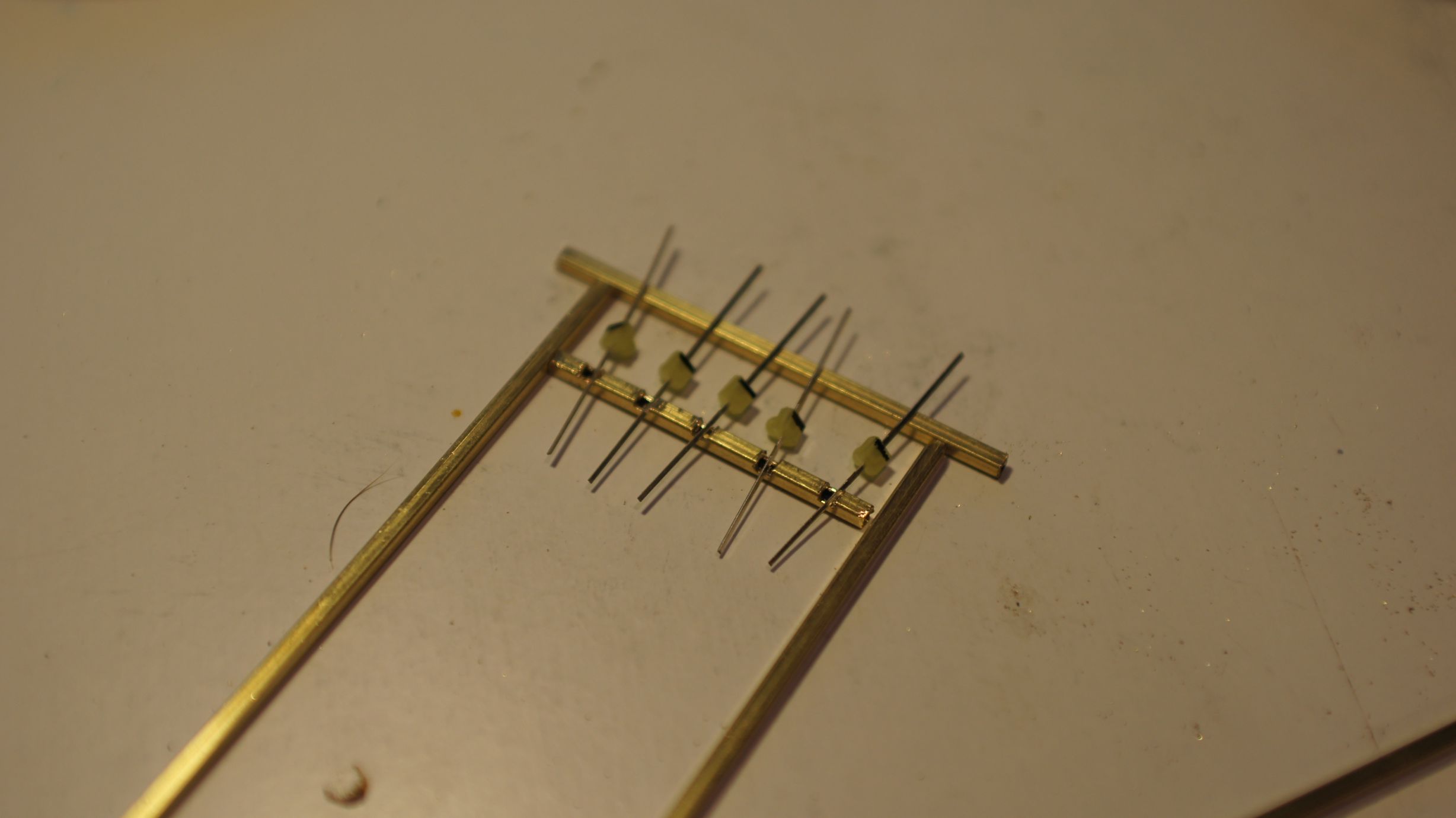
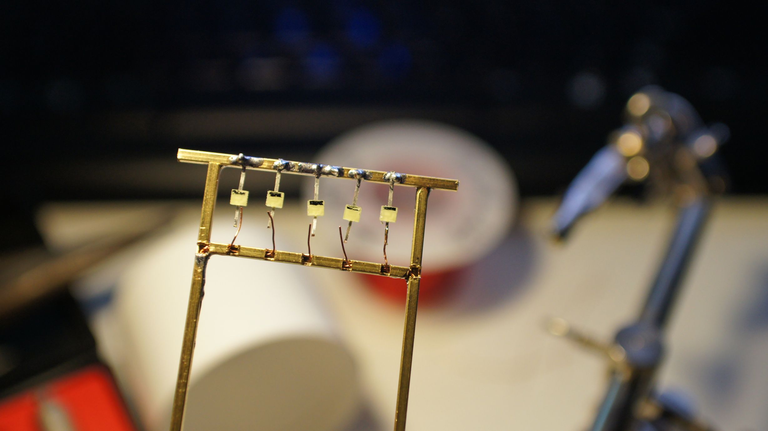
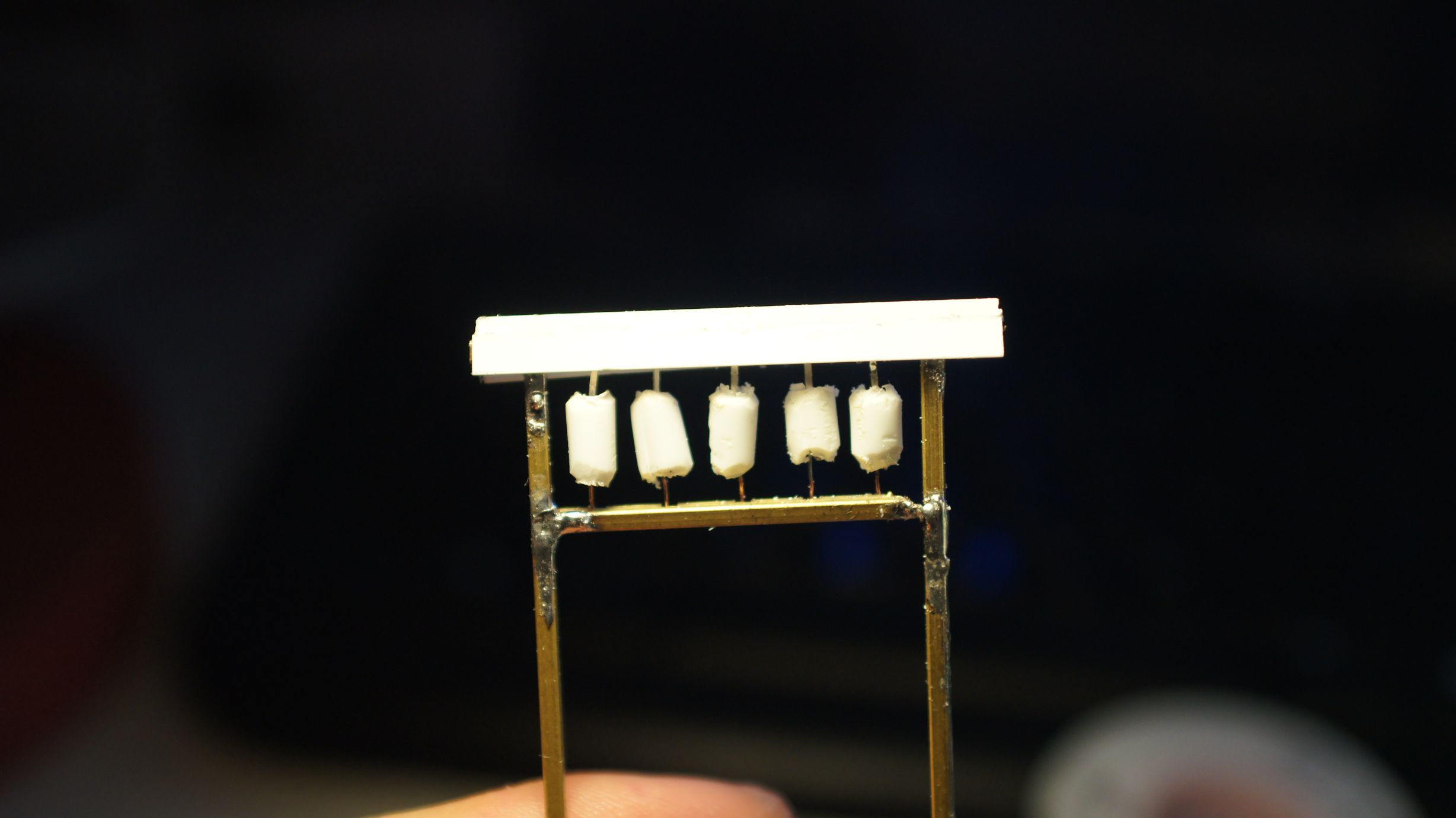
Now that the frame and LEDs were in place, I could go about turning them into lanterns. This would be done by putting plastic piping around them. I had already done this with a fixed lantern on a TomyTec Japanese Shop, but this time I had no existing lanterns to work with. I therefore used the same concept as tanaka_ace.
Thanks to globalisation, I was able to acquire the exact same "Evergreen Scale Models" poly-piping that he used. I happened to purchase 3.2mm pipe instead of the 2.4mm; but this worked out well as the LEDs that I was using were a little bigger. The pipe was cut into appropriate lengths and then the edges rounded down to create the lantern shape. The individual lanterns were then sliced at the back so that I could slide them over the LEDs. I then used stock-standard Shelleys Aquadhere to fill in the ends.
Once these were holding in place, I painted the frame a nice wood-brown. Torii gates can be made of wood or stone and painted a multitude of colours. You more often than not will see them in brown wood, but bright red, and even out in the ocean, is not uncommon.
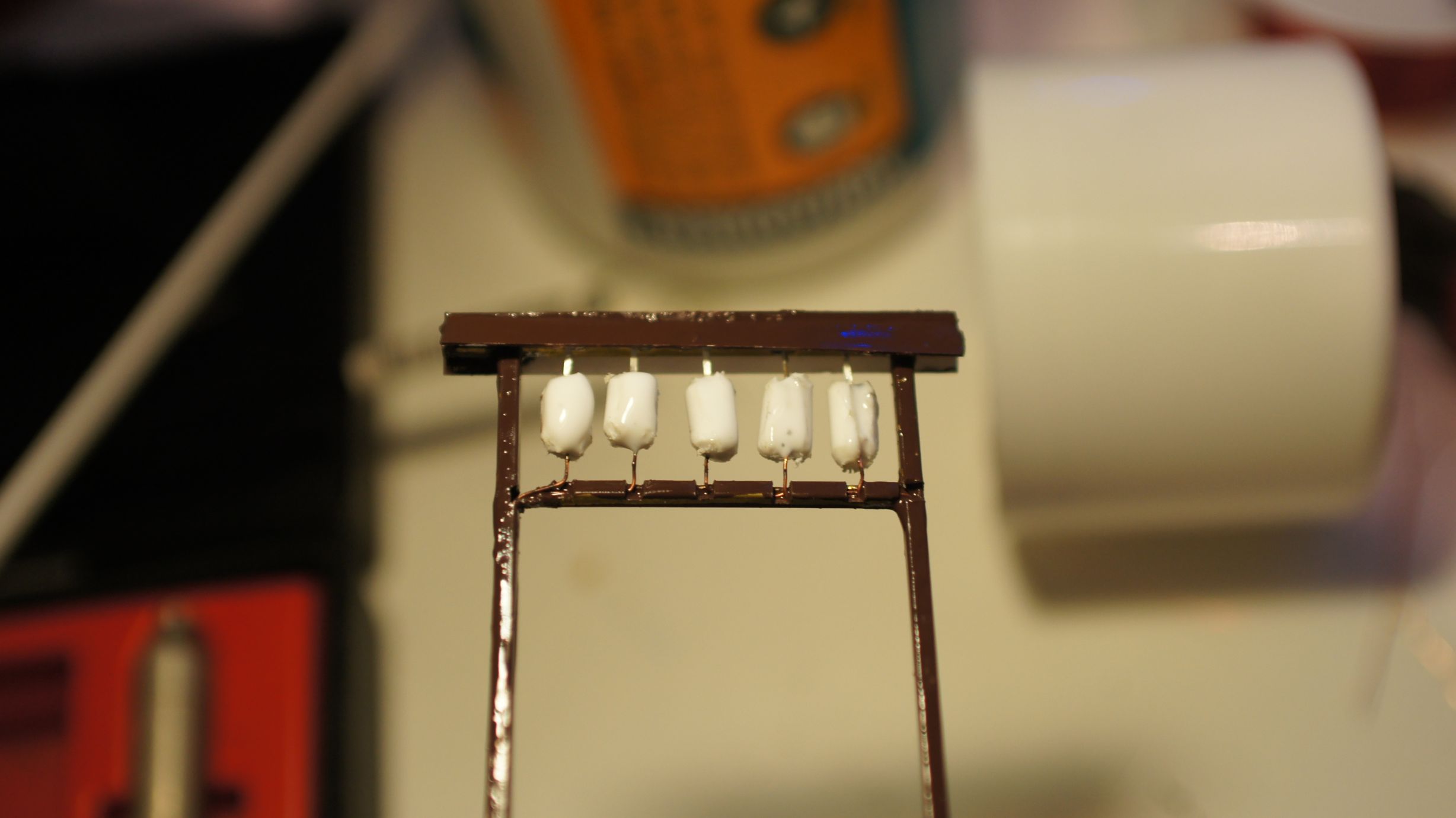
And that was it... I still think I need to place some characters on the lanterns, but I need to work out what to write on them. I also should've taken more care to get the lanterns even, but I was happy enough with the outcome and, once in place on the layout, knew it would be good enough.
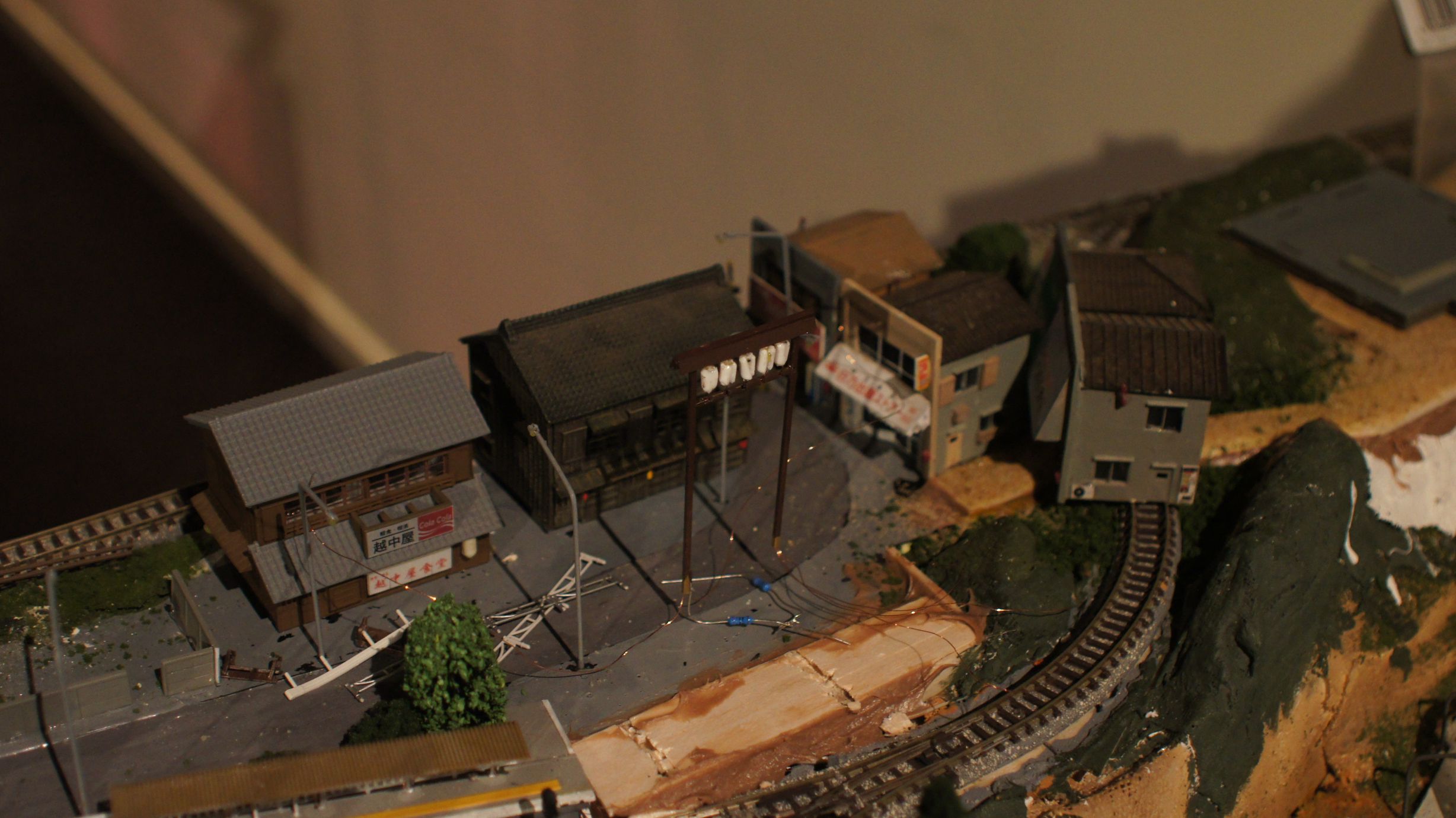
Now that the entrance is in place, it's time to get the fences and shrine in. As you can see, the foundations are there already and I'm currently working on adding lanterns and lights to the shrine.
The Southern Spirit – January 2011
I'd checked out The Southern Spirit before, but this time I thought I'd chase it across the state. It's inaugural 2011 voyage was to be from Adelaide to Brisbane starting over the weekend of the 29th and 30th of January.
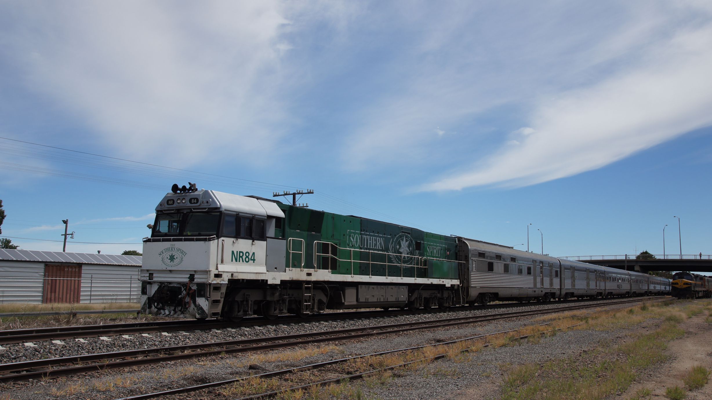
The Southern Spirit
This train, run by Great Southern Railways, is a once-a-year (although it'll be running the 'journey' twice this year) special service run from Adelaide to Brisbane and return. It's quite a long trip and the journey includes stopovers at stations along the way; including bus tours to local attractions. The train is targeted at people with a large amount of disposable income and a lot of time to spare... you can therefore imagine the average age of the passengers on-board is around 65. Check out more information on The Southern Spirit on the GSR website.
Timetables
I'd done a little investigation and found that The Southern Spirit was to cross 2 freight trains (one twice) and then The Overland. I knew The Overland would be more-or-less on time (when compared to freight) and so decided to start my planning around it. I'd leave Melbourne bright and early and get to Ararat in time for a midday photo of The Overland dropping through. I'd then head west, watch it meet The Southern Spirit and then return home. The Southern Spirit was to stay overnight out west and I would catch up with it again in Melbourne the next morning.
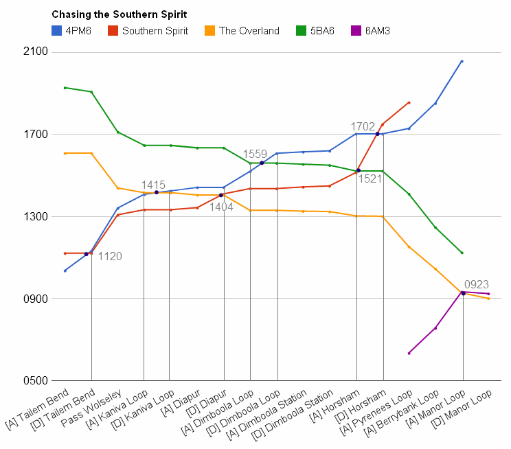
I drew up a diagram, similar to a 'diamond' (a popular Japanese method of showing train paths intersecting), of the trains that would be around the area for Saturday. The y-axis was slightly useless, so I labeled the passing locations and times. Note that 4PM6 didn't show the standard times as it had been modified by ARTC to stop in certain loops to allow trains to pass it. I'd also listed Manor Loop in there, as The Overland was scheduled to pass a freighter; but I've never seen this happen and probably wont get up early for it.
The goal was now set, I was to get to as many of the passes as possible. I also wanted to stop at locations along the way to get the trains in action. Unfortunately, I've never been this way and had no idea where to stop. I also had to make sure I kept to the times as most services would have an NR locomotive on the front and they aren't scared to do line-speed.
| Location | Google Time | Better be moving by | Deadline |
|---|---|---|---|
| Melbourne to Ballan | 1 hour 7 minutes | 0720 | 0829 : V/Line Ballarat to Melbourne |
| Ballan to Beaufort | 59 minutes | 0900 | 1007 : V/Line Ballarat to Ararat |
| Beaufort to Ararat | 35 minutes | 0958 ## | 1033 : V/Line Ballarat to Ararat 1147 : Overland at Ararat |
| Ararat to Diapur Station | 2 hours 23 minutes | 1140 ** | 1342 : Southern Spirit at Diapur Station 1404 : Overland pass Southern Spirit |
| Diapur Station to Dimboola Station | 50 minutes | 1358 | 1443-1448 : Southern Spirit at Dimboola |
| Dimboola Station to Horsham | 30 minutes | 1445 | 1513 : Southern Spirit arrives Horsham 1521 : 5BA6 pass Southern Spirit |
| Horsham to Dimboola Station | 30 minutes (to Station) ~32 minutes (to Loop) |
1523 | 1559 : 5BA6 pass 4PM6 (at Loop) 1614-1619 : 4PM6 (at Station) |
| Dimboola Station to Horsham | 30 minutes | 1626 | 1702 : 4PM6 pass Southern Spirit 1748 : Depart Horsham |
| Horsham to Ararat | 1 hour 15 minutes | 1745 | 1900 : Southern Spirit arrives Ararat |
## Seems the Regional Fast Rail to Ararat can beat me from Beaufort to Ararat.
** Check that out, The Overland is still meant to be at Ararat Station until 1147 but I need to get going at 1140 (based on Google's time estimate) to see it at the pass The Southern Spirit at 1404 at Diapur Station.
After google'ing the locations, directions, distances and times... it occured to me that catching all of the above passes would be quite a challenge. If the trains did in-fact run at their tabled times, then I would pretty much be neck-and-neck with them along each leg. This wouldn't allow time for any in-between shots. Fortunately I'd still be just-in-time for the passes in each of the loops.
Determining the locations of the 'loops' versus the 'stations' was a little tricky. Fortunately the Vicsig Website has a complete detailed plan of the 'Western SG' line and gives you the distances of the loops from certain landmarks. Google maps didn't know where 'Dimboola Loop' was, but after a little research I found out it was around 5km north/west of Dimboola. It also looked quite difficult to get to from the Western Highway, so I decided to skip the 1559 passing of 4PM6/5BA6 and instead chose to wait for the latter at Dimboola Station.
Now, planning is all well and good when the trains follow their paths... unfortunately this isn't always the case. The Gheringhap Loop Sightings Website has a well-documented list of train movements through the Gheringhap Loop (near Geelong) and it shows, specifically last Saturday, that the two east-bound trains were up to 6 hours late, with 4PM6 being 1.5 hours early. This, to say the least, is disconcerting. The contingency plan was to take all roads as close to the railway as possible and keep an eye out for anything out of the ordinary.
Note: The entire photo gallery of this trip is located here.
V/Line in Country Victoria
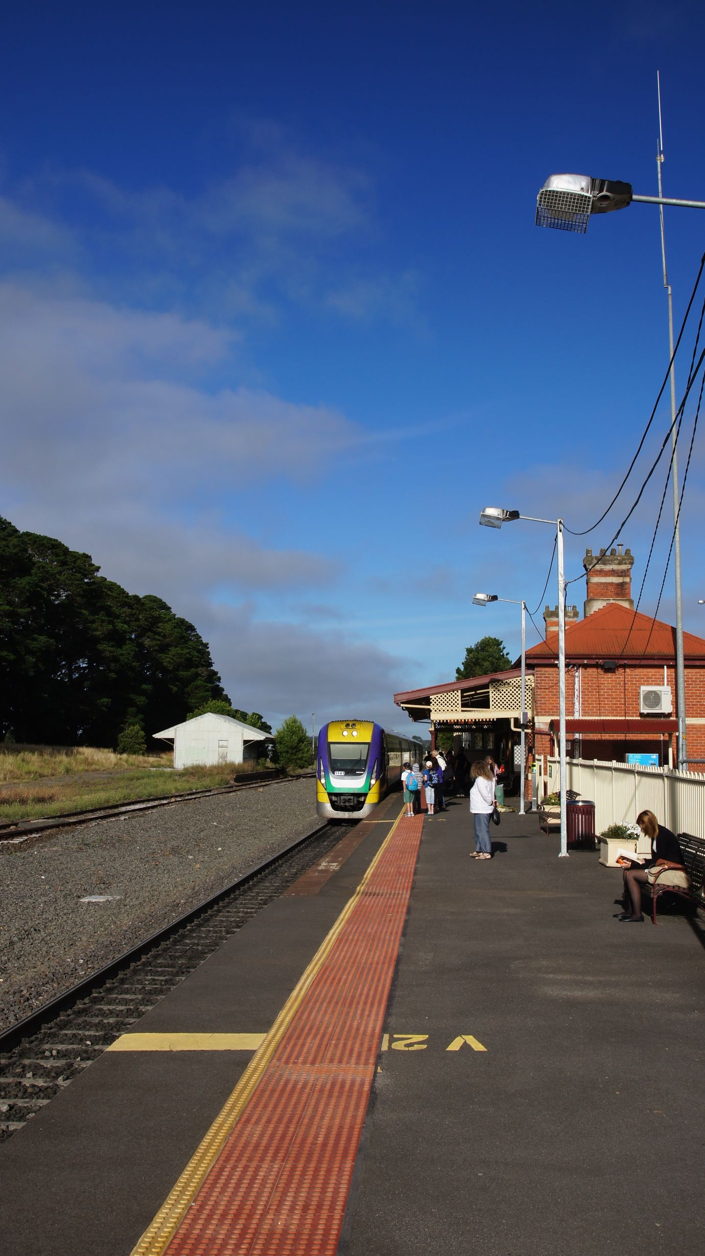
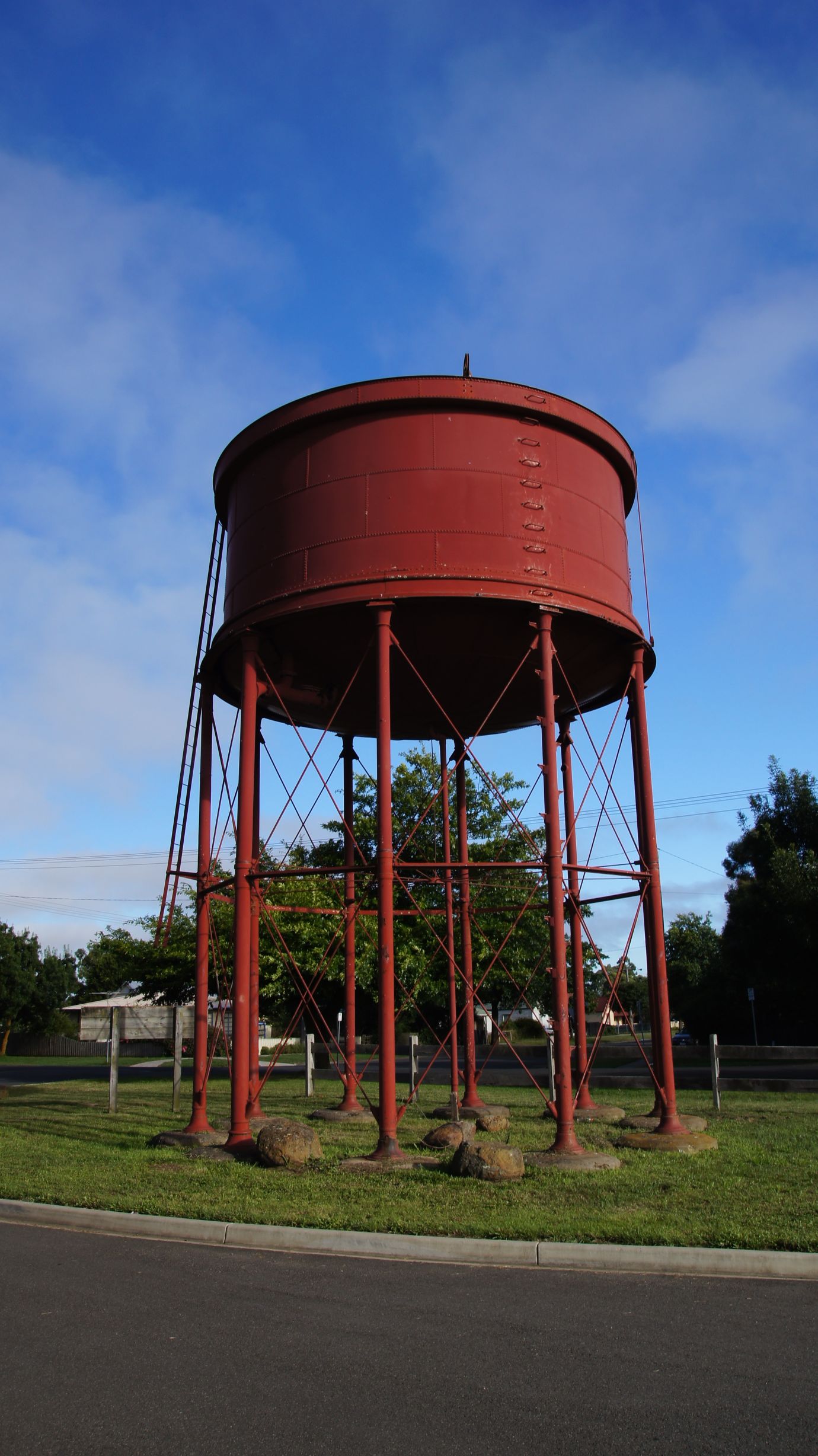
The plan was in place and we started out for Ararat at 7am on Saturday the 29th of January, 2011. Our first stop was Ballan and this was made in good time. Google had indicated over an hour, but the trip was easily done, without speeding, in 55 minutes. Here we saw a single V/Line V/Locity DMU arrive on it's way to Melbourne. There's also a nice water tank in the Station carpark.
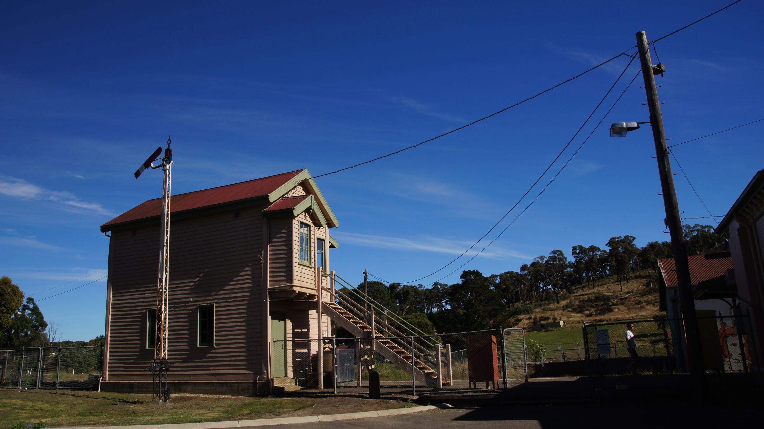
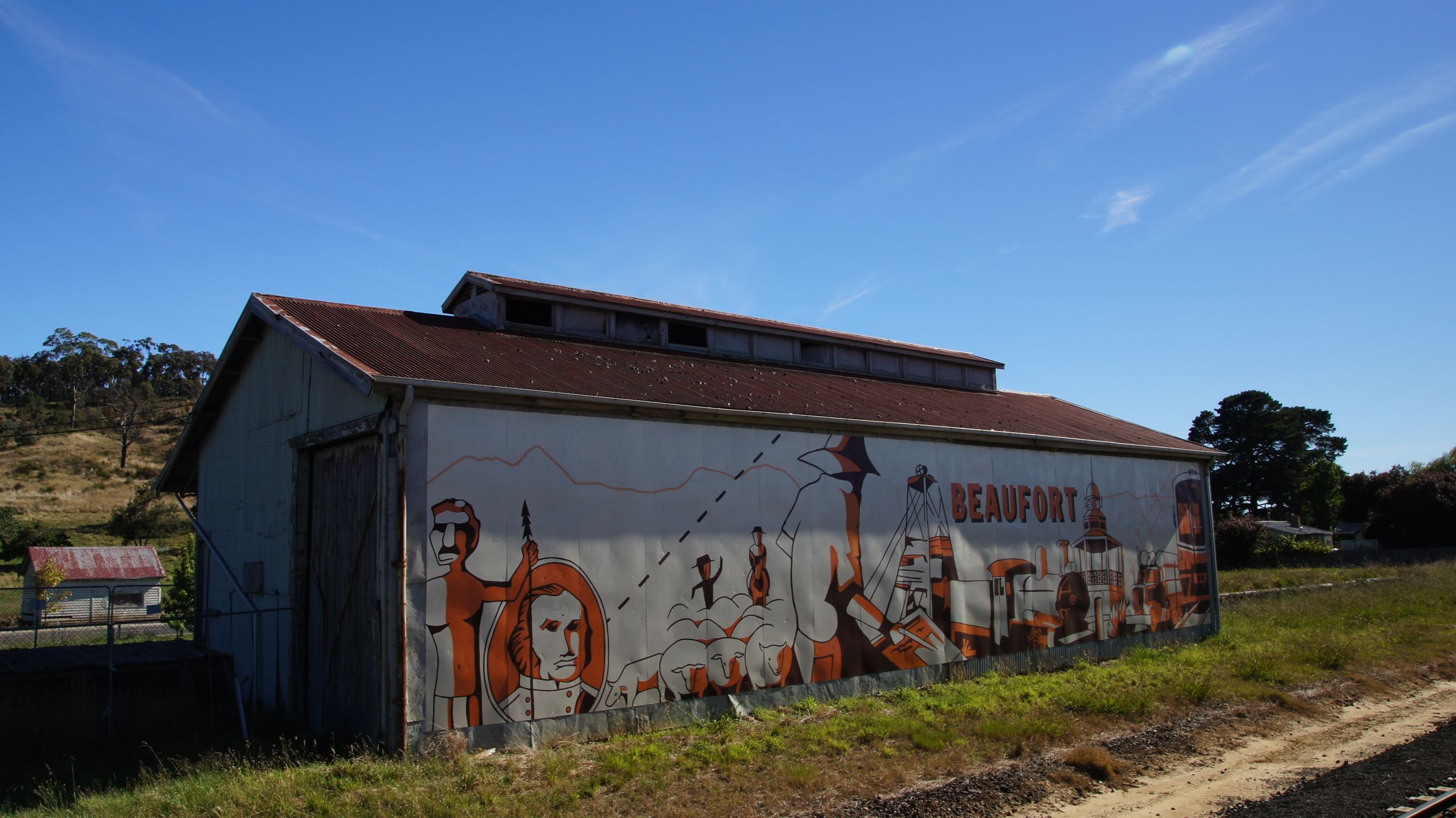
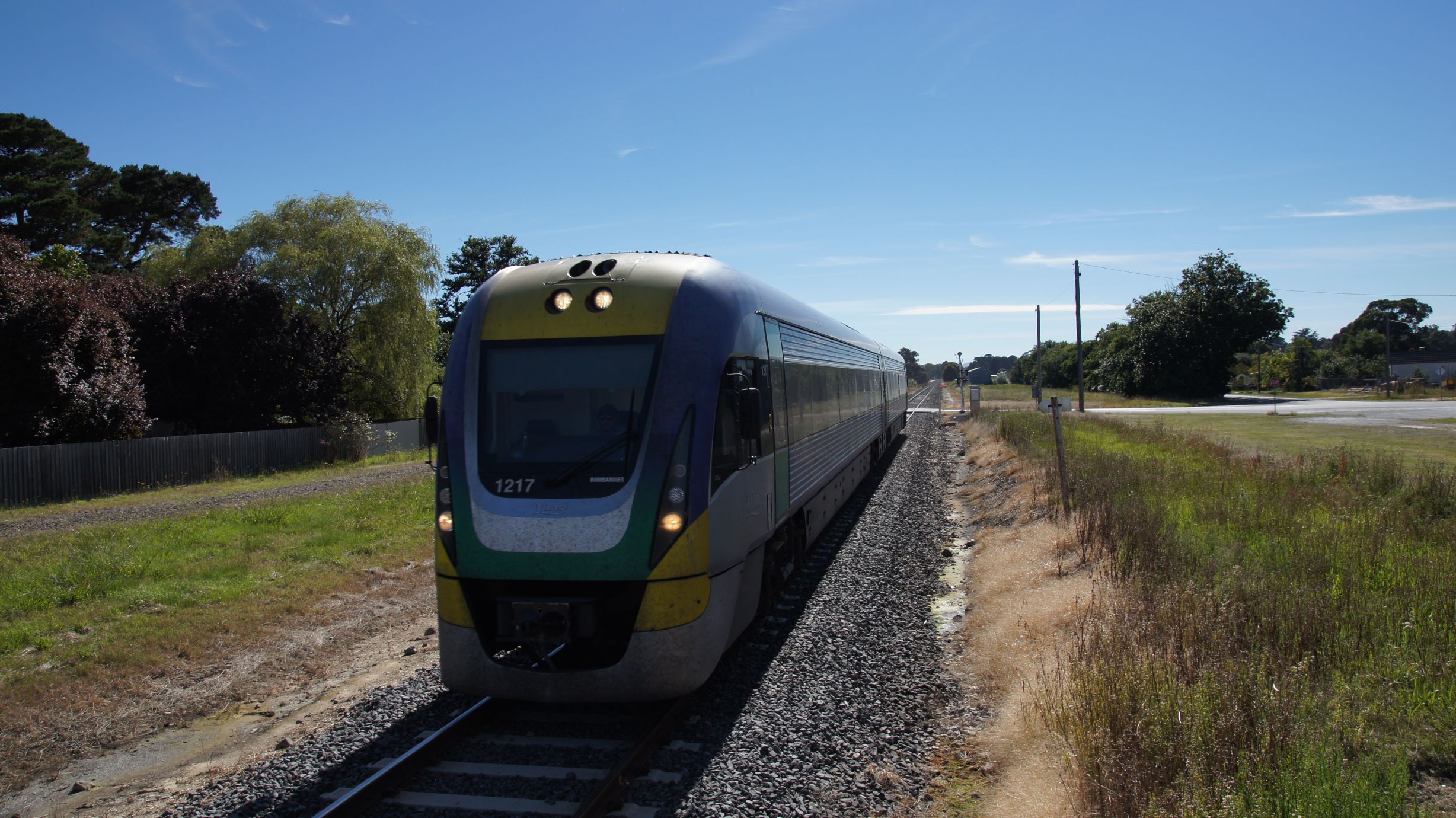
We then proceeded to Beaufort, bypassing Ballarat. Here we met the first service from Melbourne to Ararat. Again, the trip was quicker than what Google had predicted as the roads were all 110km/h running and quiet.
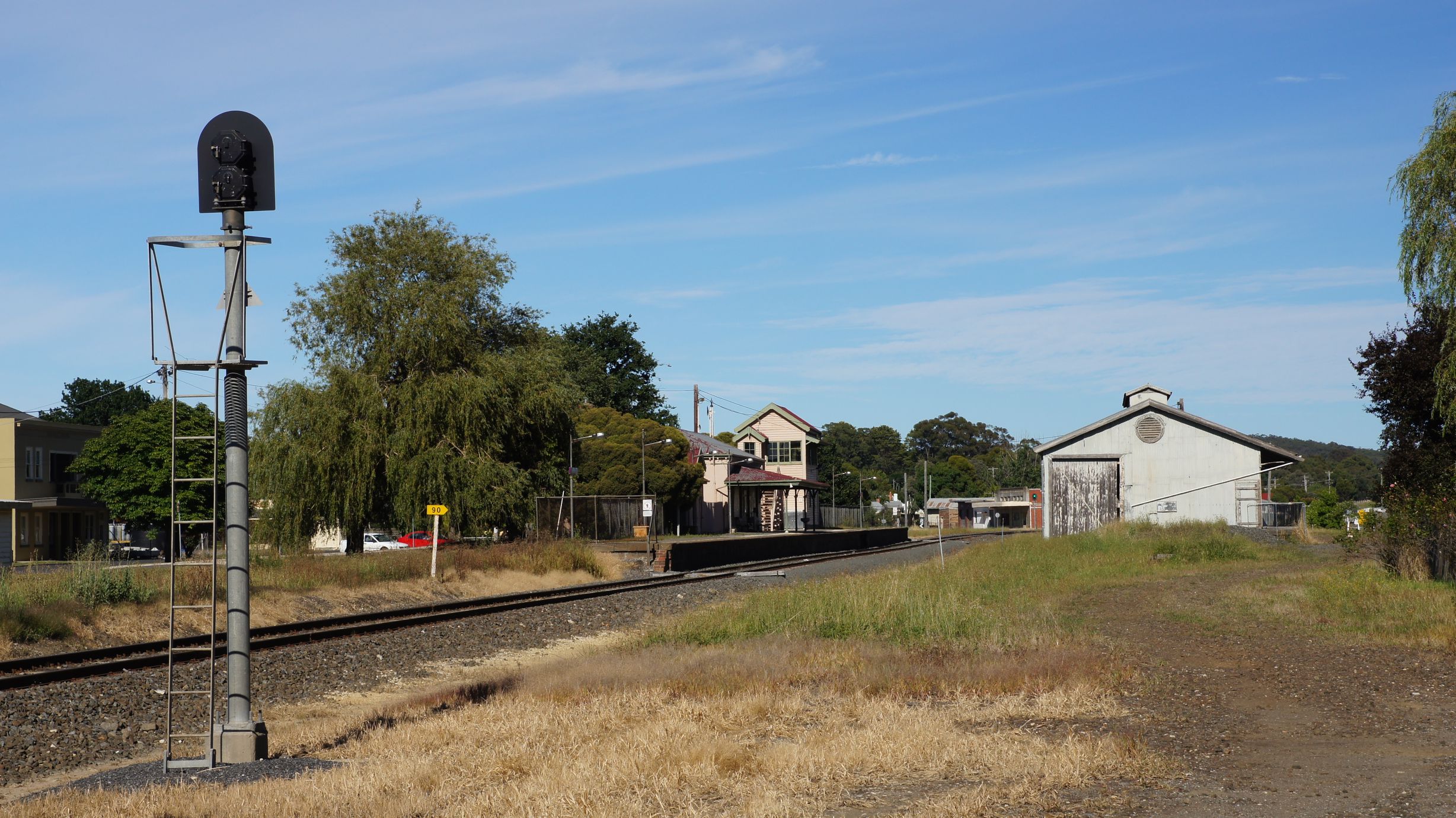
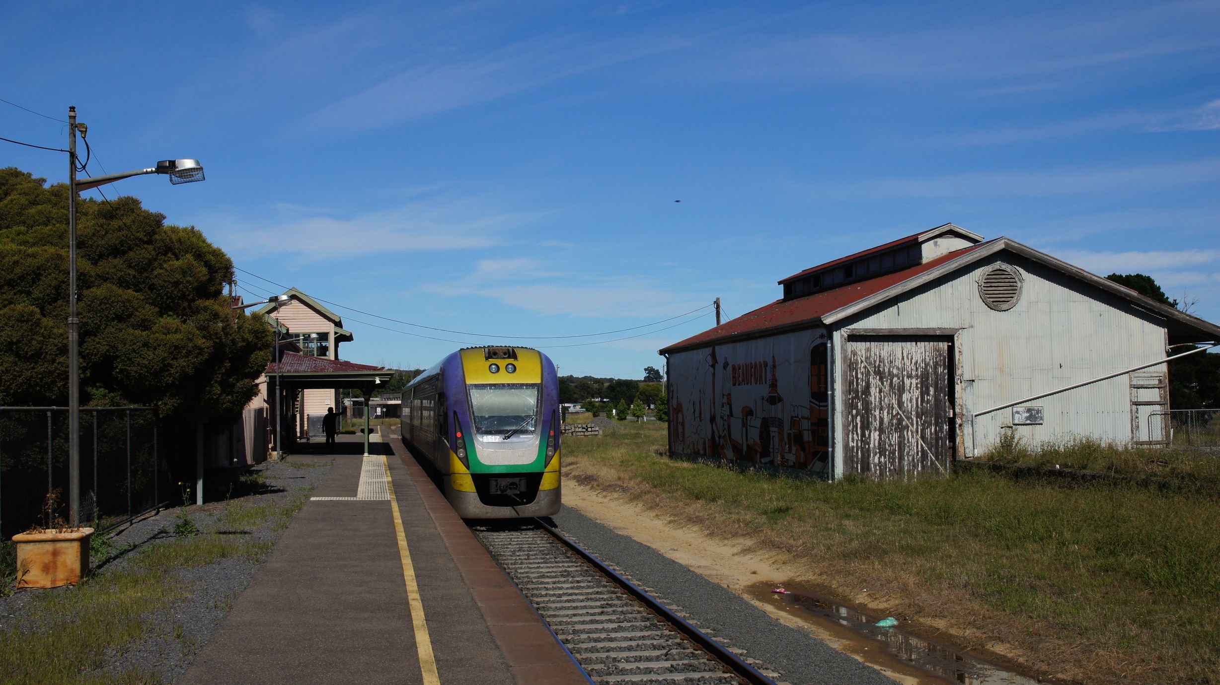
We then departed for Ararat. There was no chance of beating the V/Locity there and so we took our time. The Overland wasn't due in Ararat until 11:47 and we were easily going to be there an hour early.
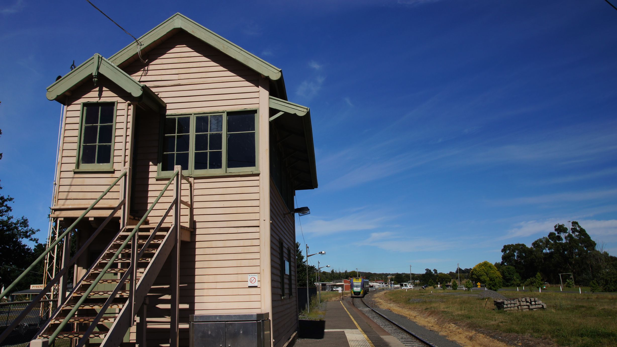
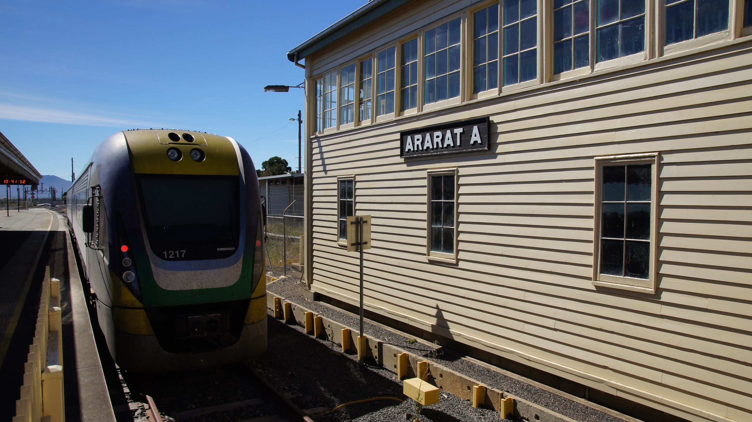
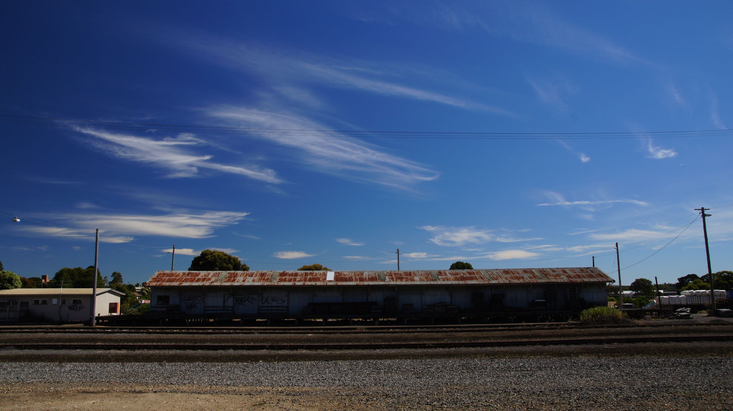
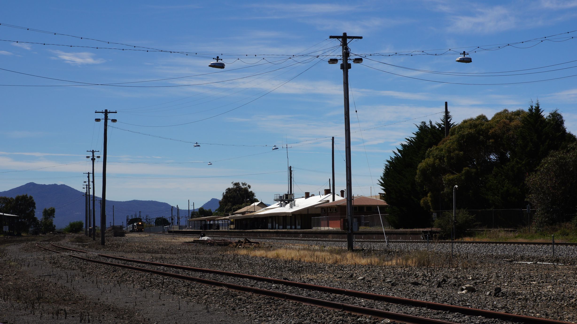
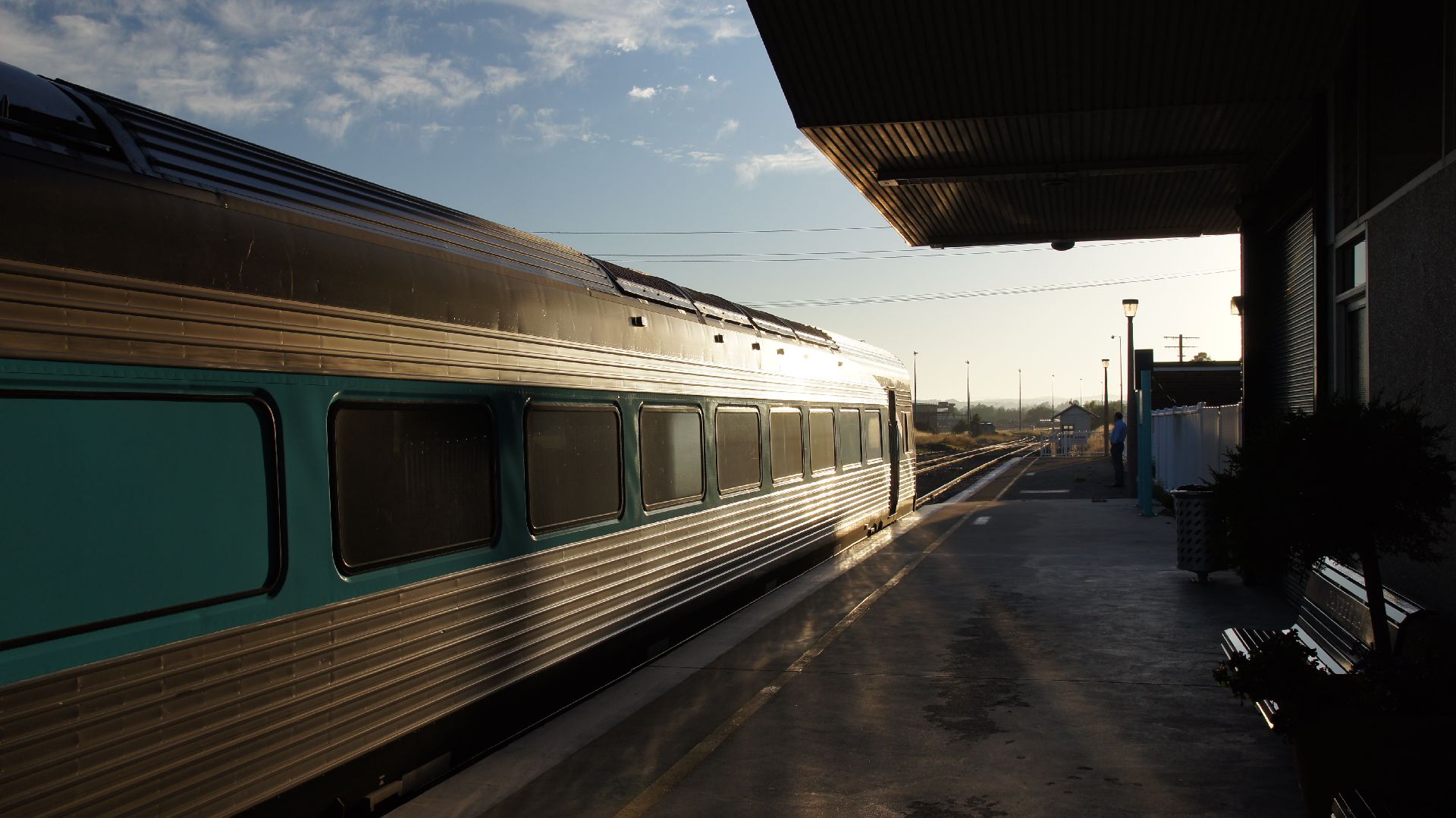
Ararat
As we arrived we saw the V/Locity terminated on the platform and used it as an excuse to check the station platforms out.
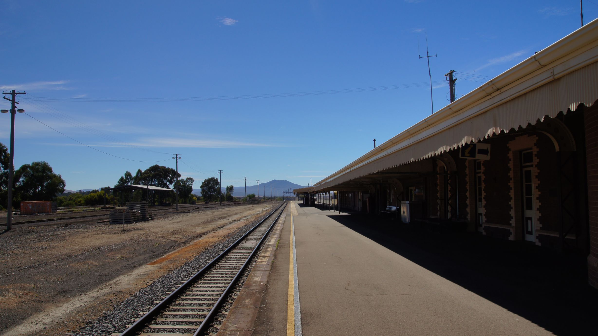
After grabbing a coffee in the main street we attempted to find a suitable position to photograph The Overland. We would need a quick departure from Ararat to meet The Overland again as it had priority on the tracks. The next station would be Horsham which was around 100km away.
Although the sun wasn't in our favour, we chose a spot on the other side of the railway, close to the highway. I also chose the wrong lens, but got a few photos of The Overland arriving at Ararat 20 minutes early.
We didn't wait for The Overland to leave... we jumped in the car and headed for Horsham. Unfortunately the roads were all 100km/h and we were passed by The Overland about 20km out of Ararat.
Horsham
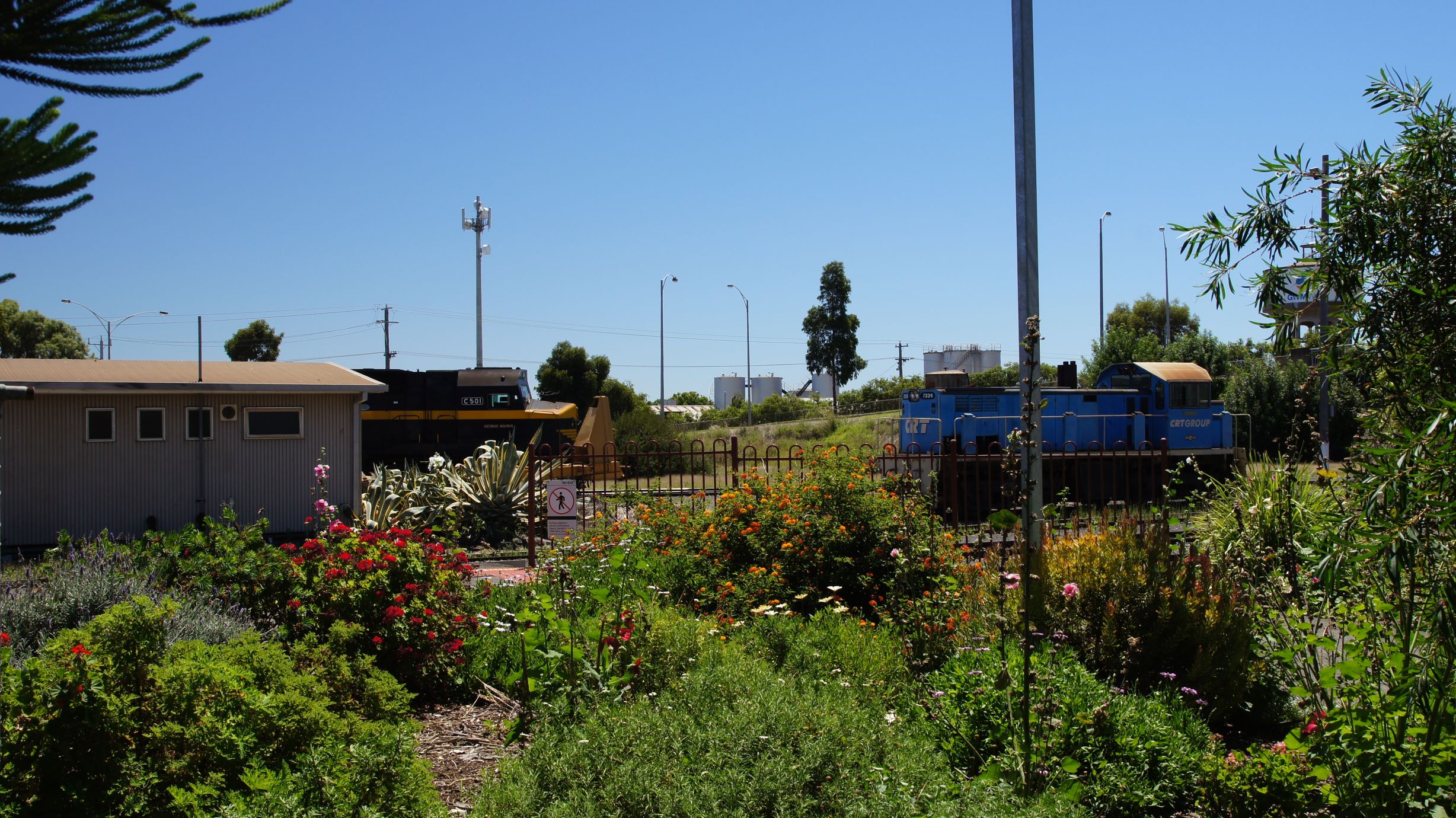
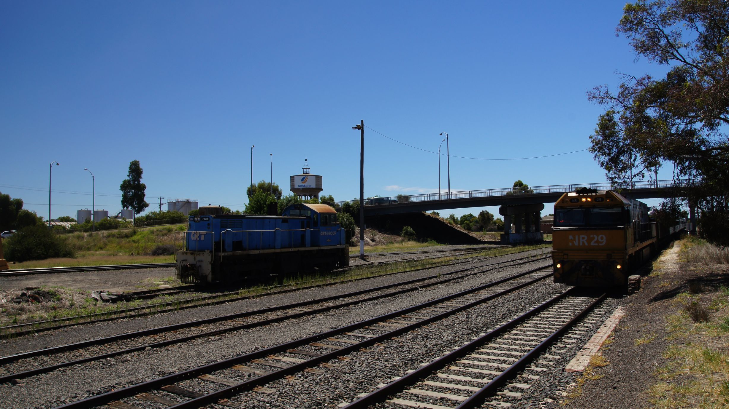
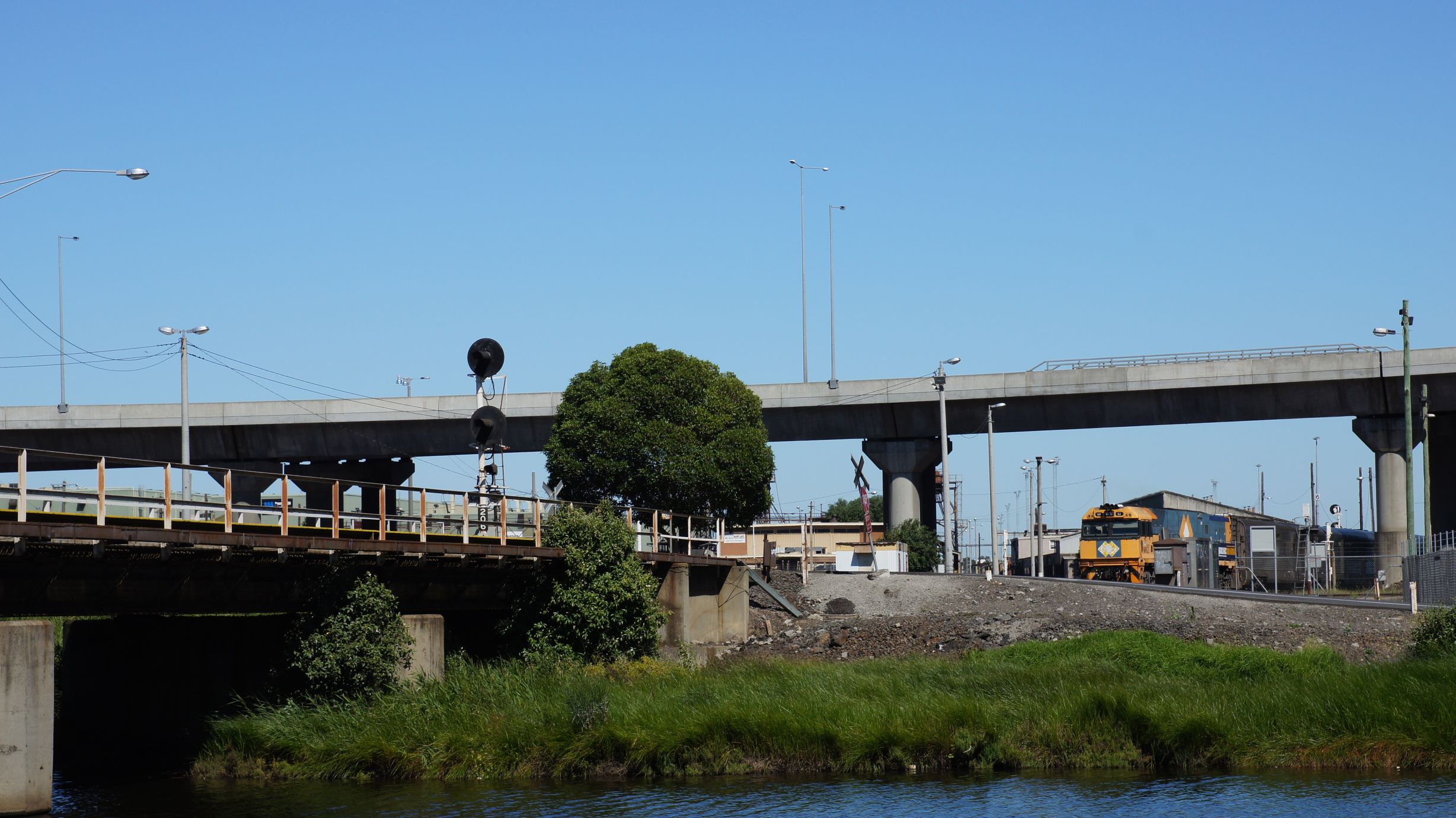
We hadn't had any visibility of the rails for around 40km prior to Horsham, but had expected that all hope was lost. It was a nice surprise that, upon arrival to the station, we found passengers waiting for the train. There were even a few freight locomotives shunting around the yard.
And then The Overland arrived.
We, again, didn't give it a chance to leave before us... We knew what it was capable of and needed a head start.
Horsham to Dimboola
This was the best part of the trip. The drivers were on to us, they knew we were tagging along. They also made us know that they were perfectly capable of beating us... blowing their horns as they passed us on the highway. The rail between Horsham and Dimboola runs parallel for 90% of the way and is great when you're running side-by-side. Unfortunately The Overland had no intention of hanging around.
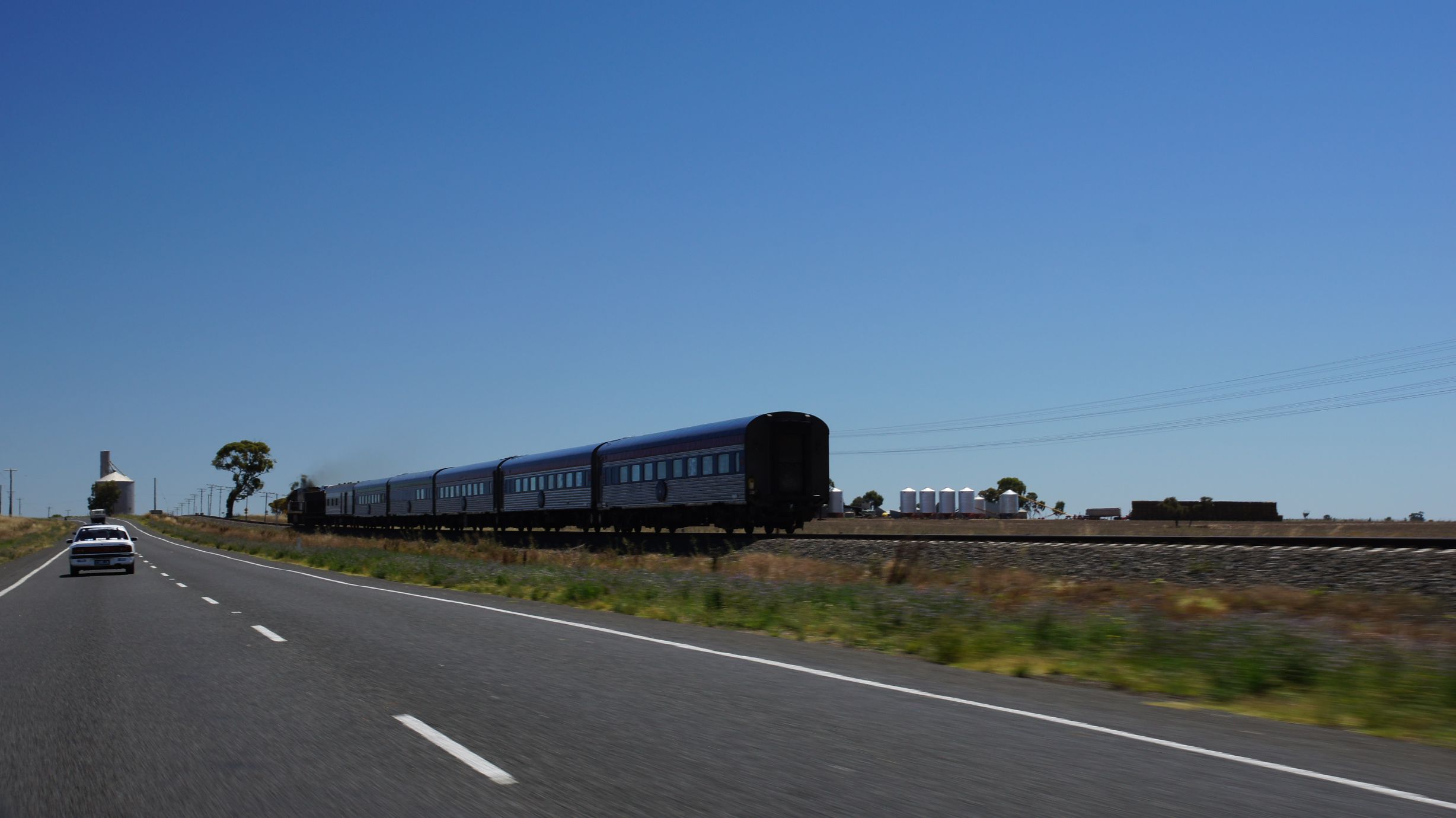
We then fell behind quite heavily and watched as the train seemed to drive across the road around corners... it really is a great sight. We proceeded to Dimboola hoping to go straight through and get another head start.
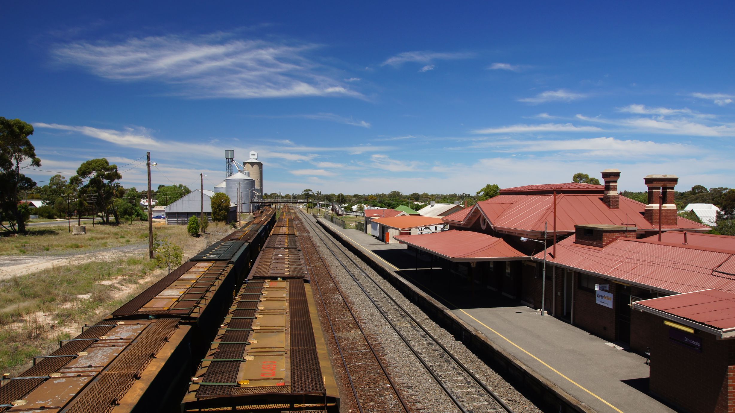
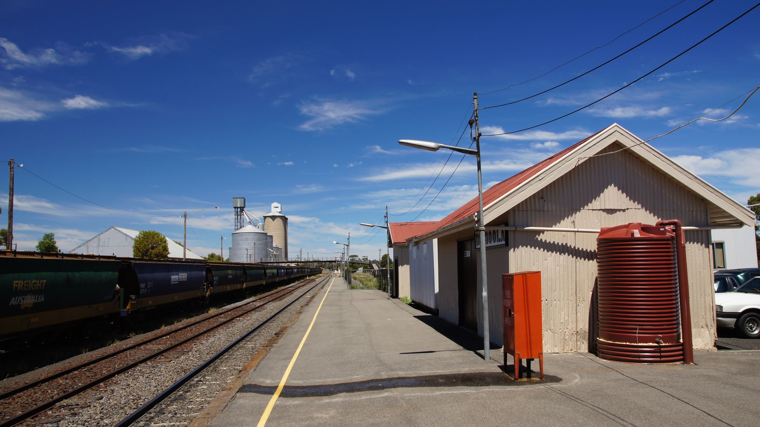
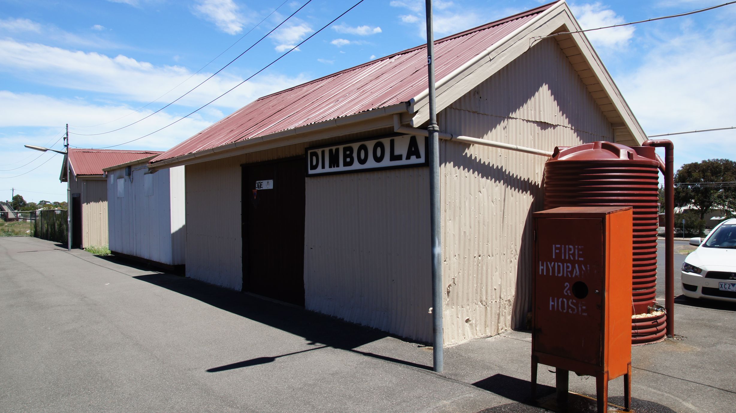
Dimboola
As we came in to the town we knew we'd been beaten. The level crossing was already quiet and, as we crossed it, we saw the tail of the train in the platform. This meant we had around 2 minutes to get in front of it. Finally the sun was on our side and we parked a few metres west of the station to watch the train depart.
Now it was decision time. The Overland was meant to cross The Southern Spirit at Diapur Station. This was around an hour away by car, but we couldn't guarantee that the roads/traffic would allow us to get there in time. We also knew that The Overland was running around 20 minutes early. This meant that, depending on the timing of The Southern Spirit, the cross could be made at another location...
We had decided to proceed through to Dimboola Loop. I'd known, thanks to the Vicsig website, that it was around the AWB facilities near Dimboola, but from the road, it wasn't easy to spot. Either way, we saw no trains around the area. We continued on, expecting to travel as far as Nhill.
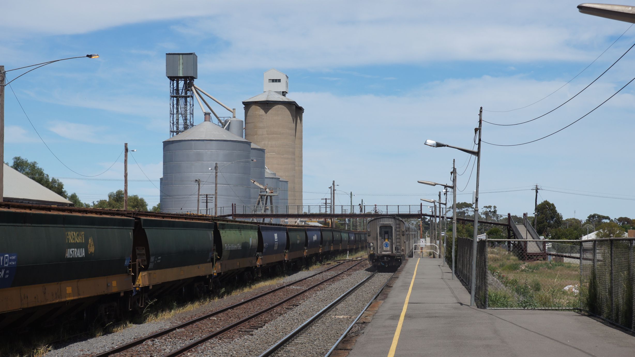
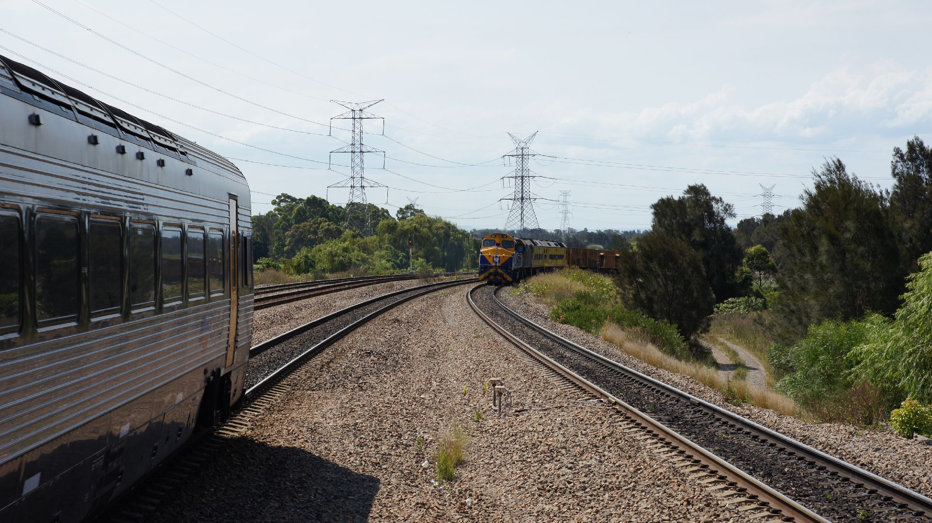
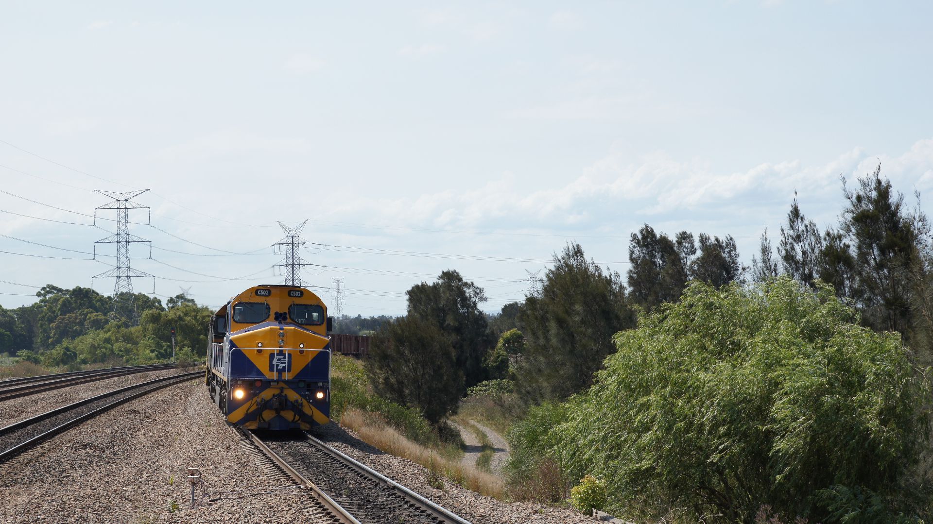
As we were around 25mins west of Dimboola, a headlight appeared on the tracks. The last thing we expected was dirty NRs on a freight train, but there was 4PM6 hurtling towards us. The Overland had already passed it, somewhere west of Dimboola Loop and the freighter had already built up speed and was heading for it's scheduled stop in Dimboola. This train was expected to be held back at Tailem Bend and was meant to run behind The Southern Spirit until Horsham but had instead been allowed to proceed.
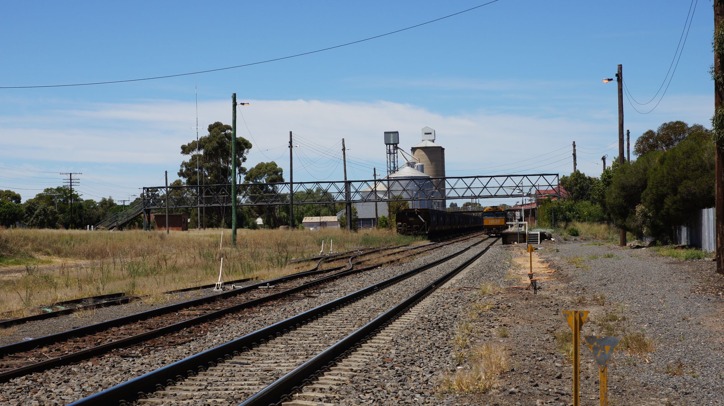
We then pulled a strategic u-turn and followed the freight back to Dimboola. This was an easy chase, as the freighter was unable to hold 100km/h on the gradients. We got back to Dimboola in time and had the sun on our side for once.
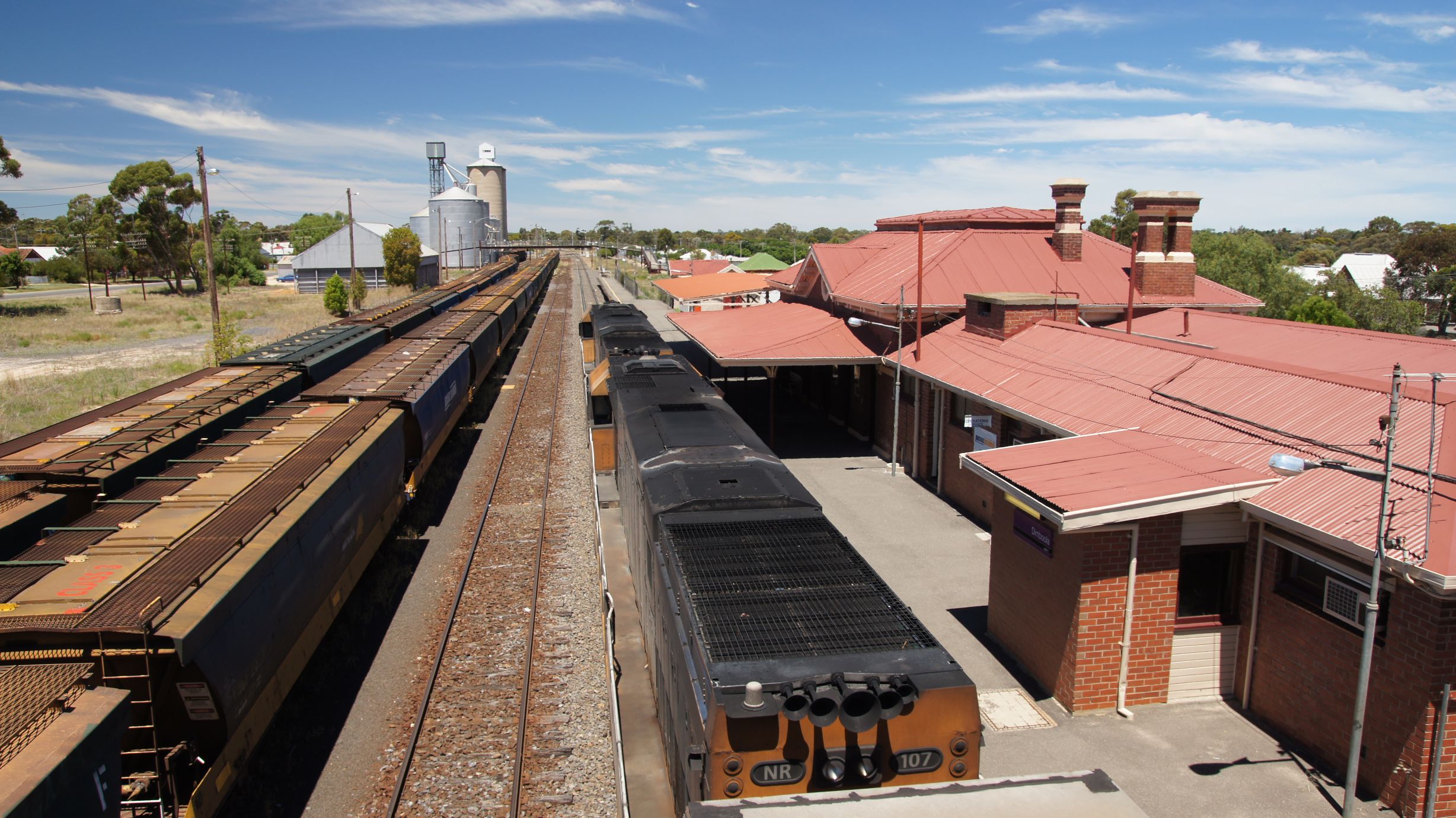
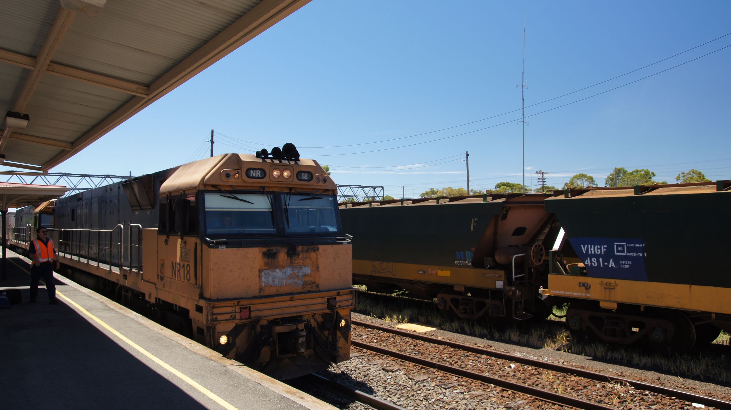
I had a quick chat to the driver who confirmed it was 4PM6 and that The Southern Spirit was due through not long after. The drivers swapped over and the freighter departed quickly. We then waited around for our first sighting.
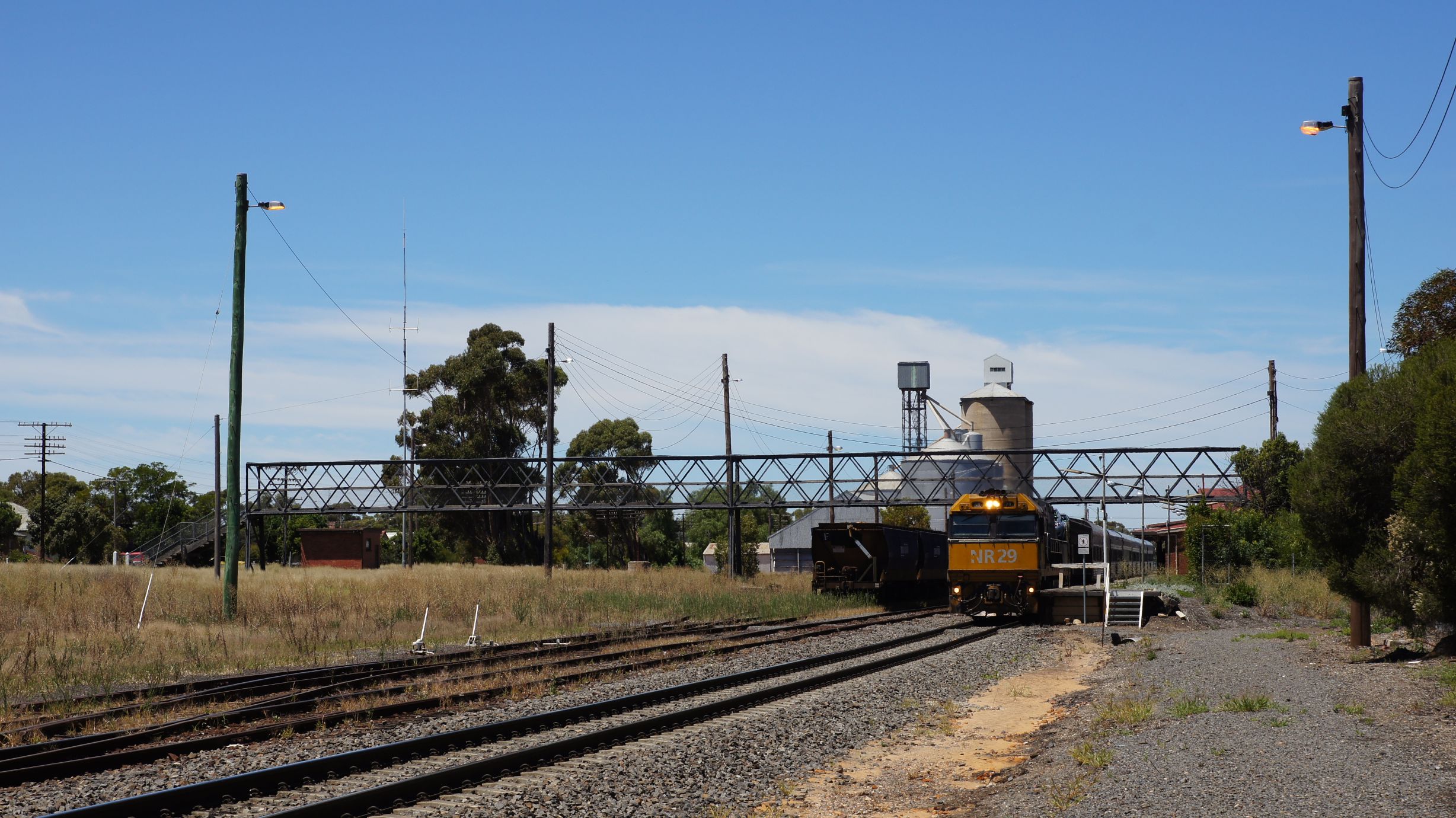
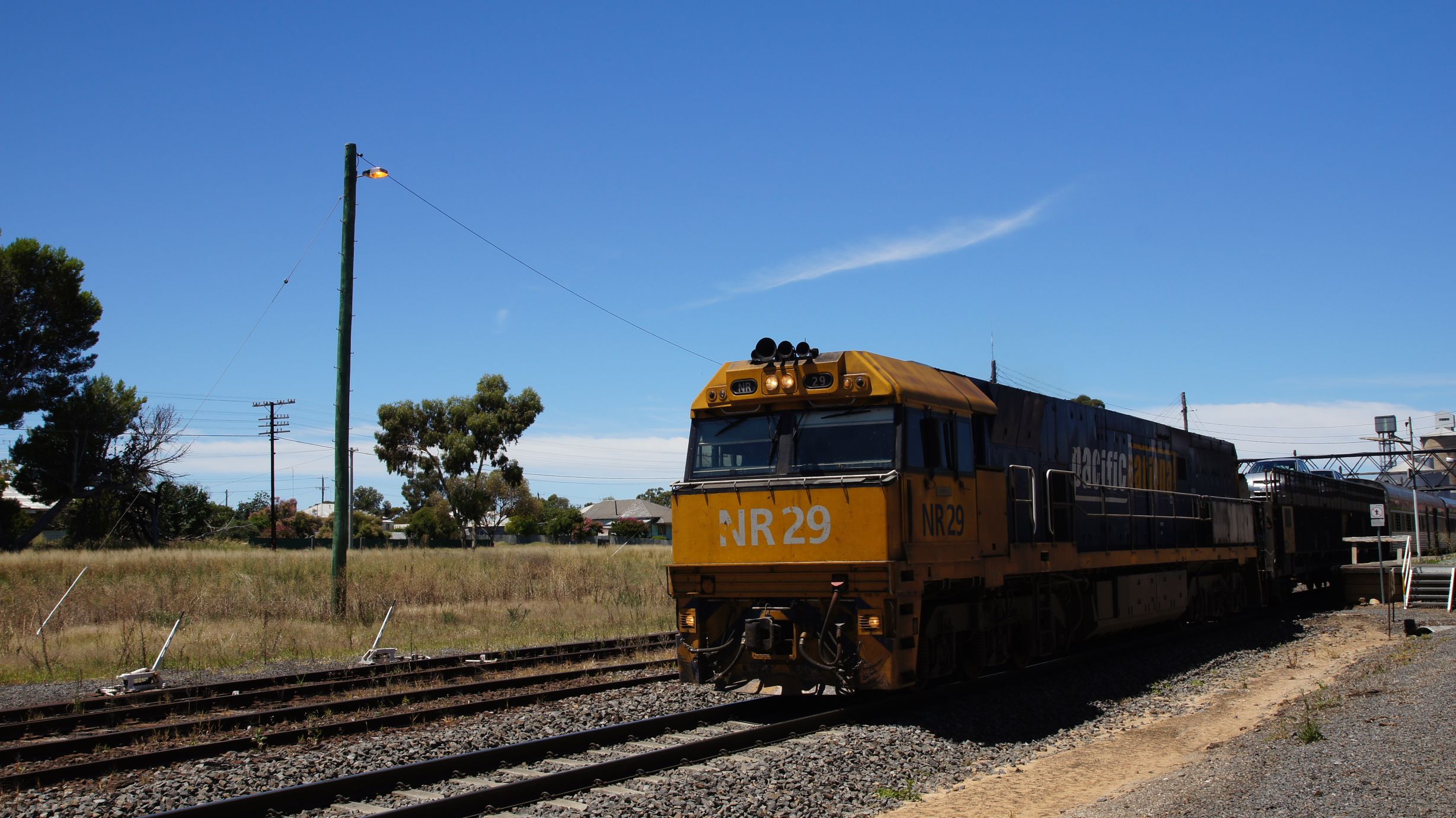
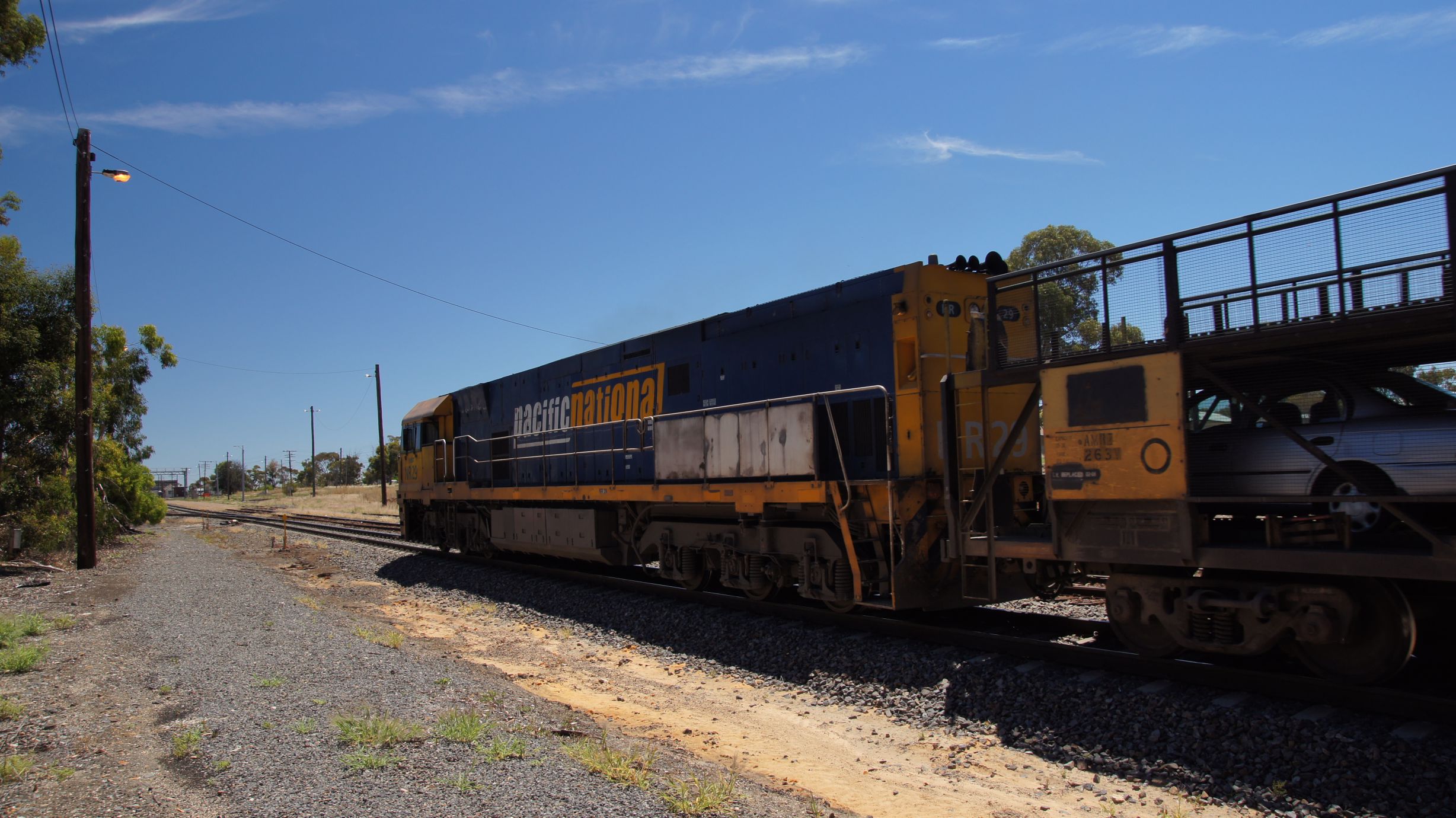
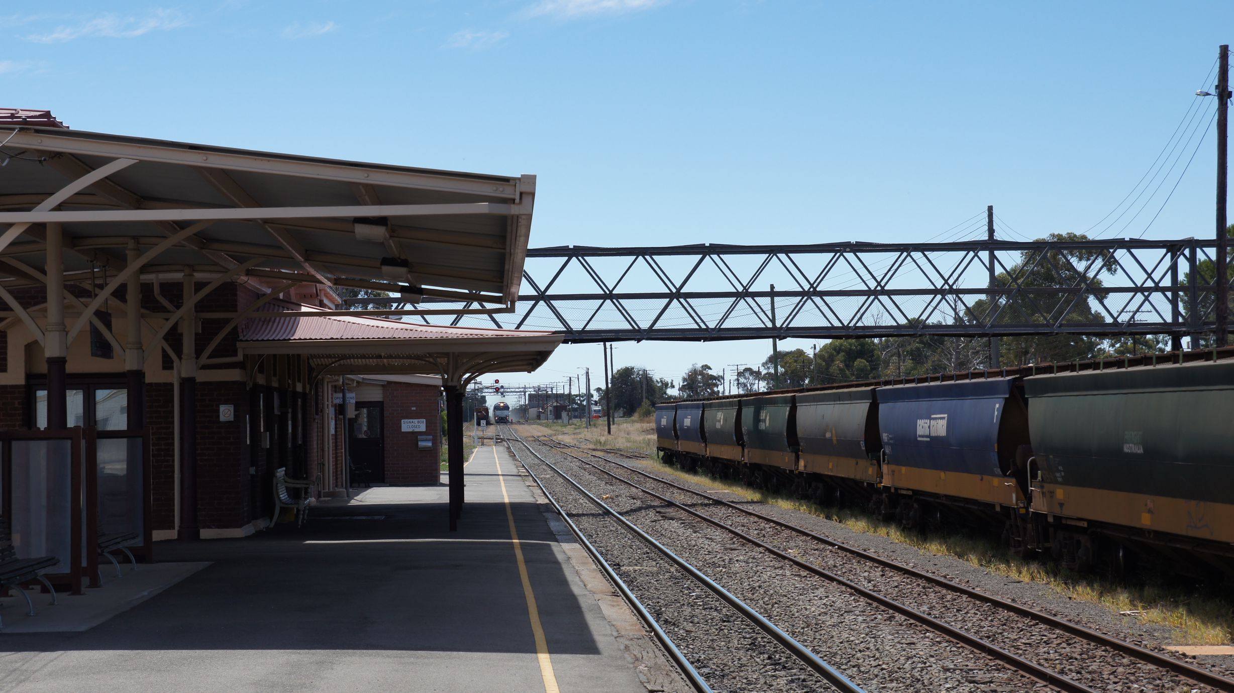
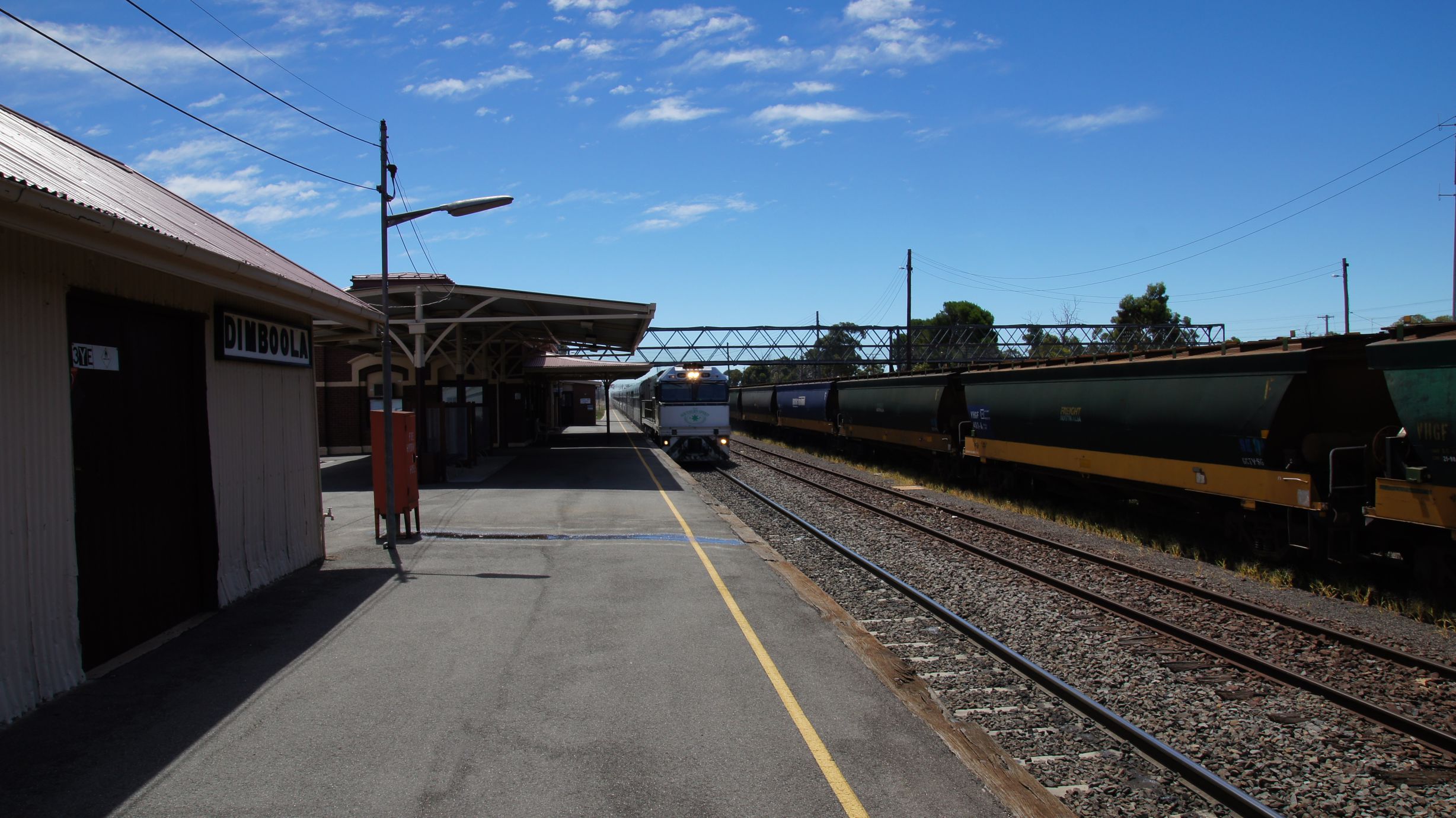
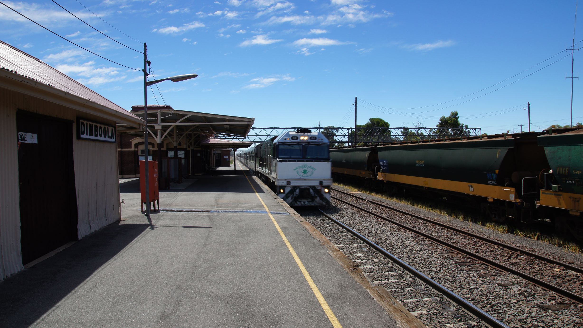
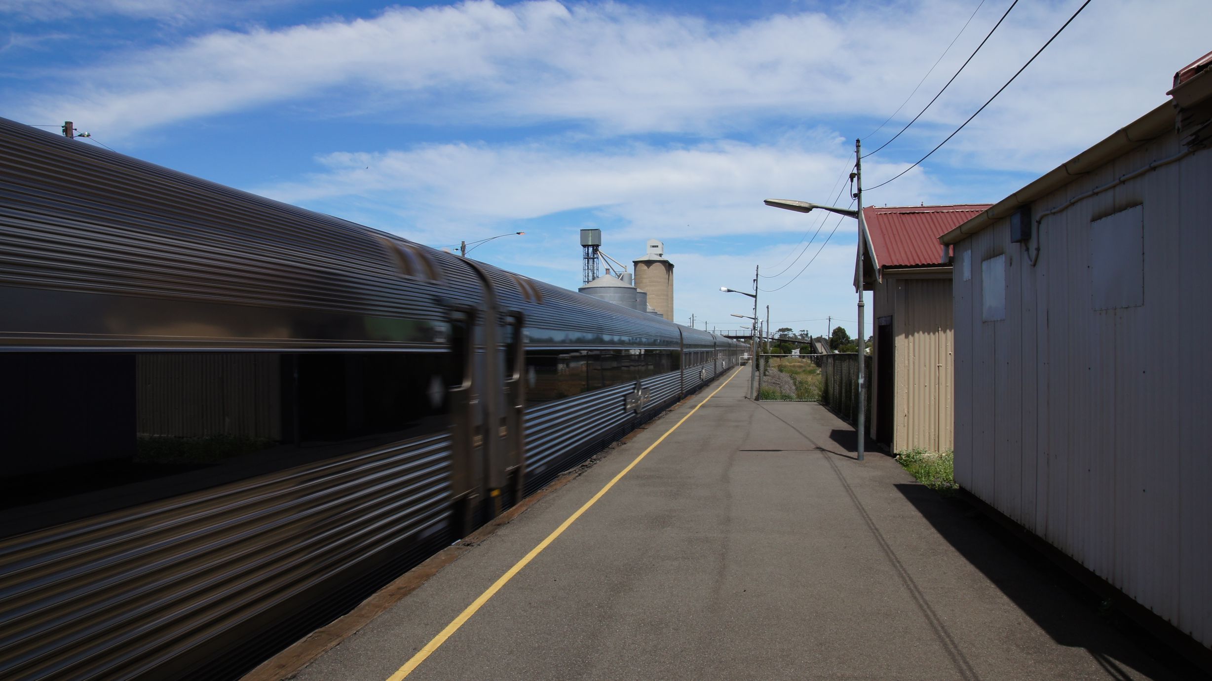
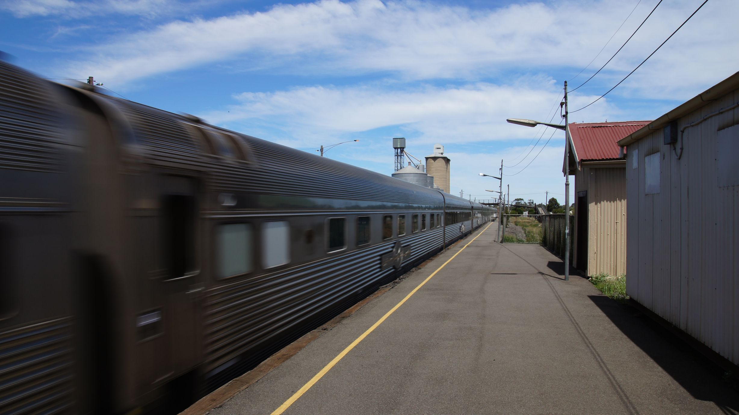
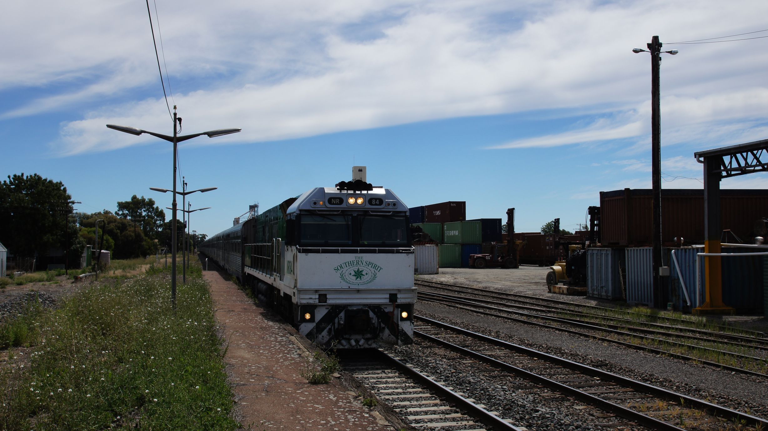
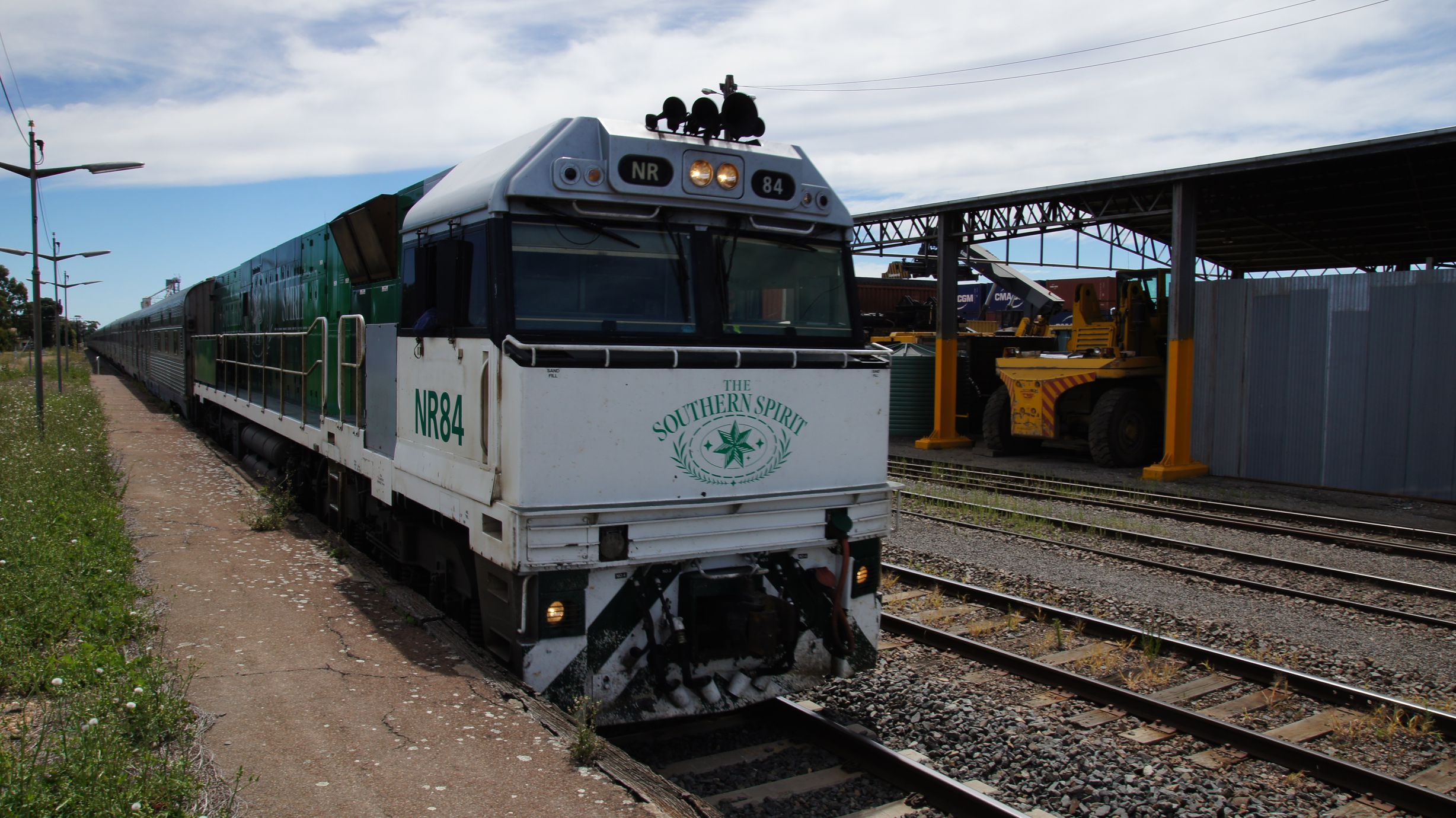
The Southern Spirit at Dimboola
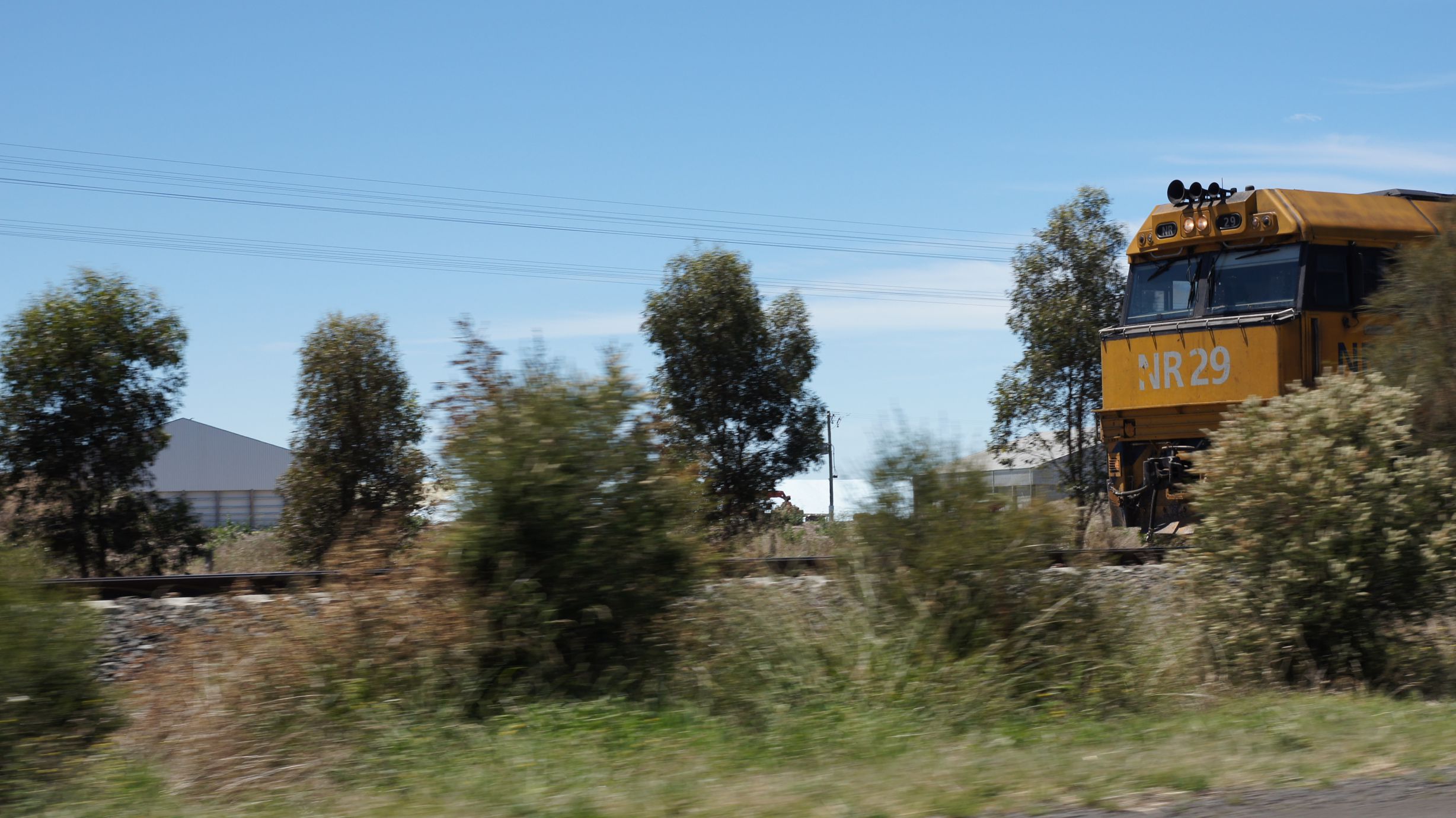
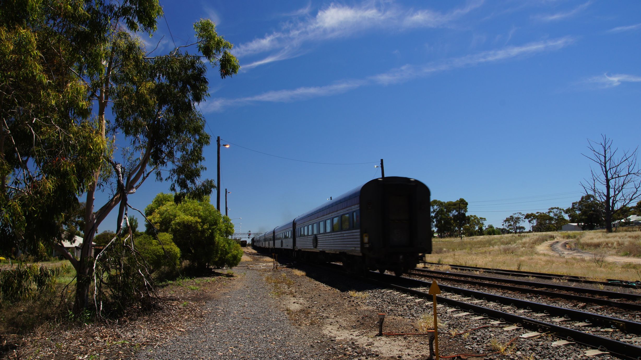
Around 35mins later we could hear an NR powering its way towards Dimboola. A headlight then appeared over the incline from the west and the next thing we knew, the whole train had passed. We had seen that the signal was green and that the train didn't have to stop but, after the freighter crawled though, we weren't expecting line-speed. I managed to scramble a few photos but, even in broad daylight, the motion blur couldn't be avoided.
We had now finally seen the train and followed it back to Horsham. There was absolutely no chance of beating it and we knew it was to stable for around 3 hours there.
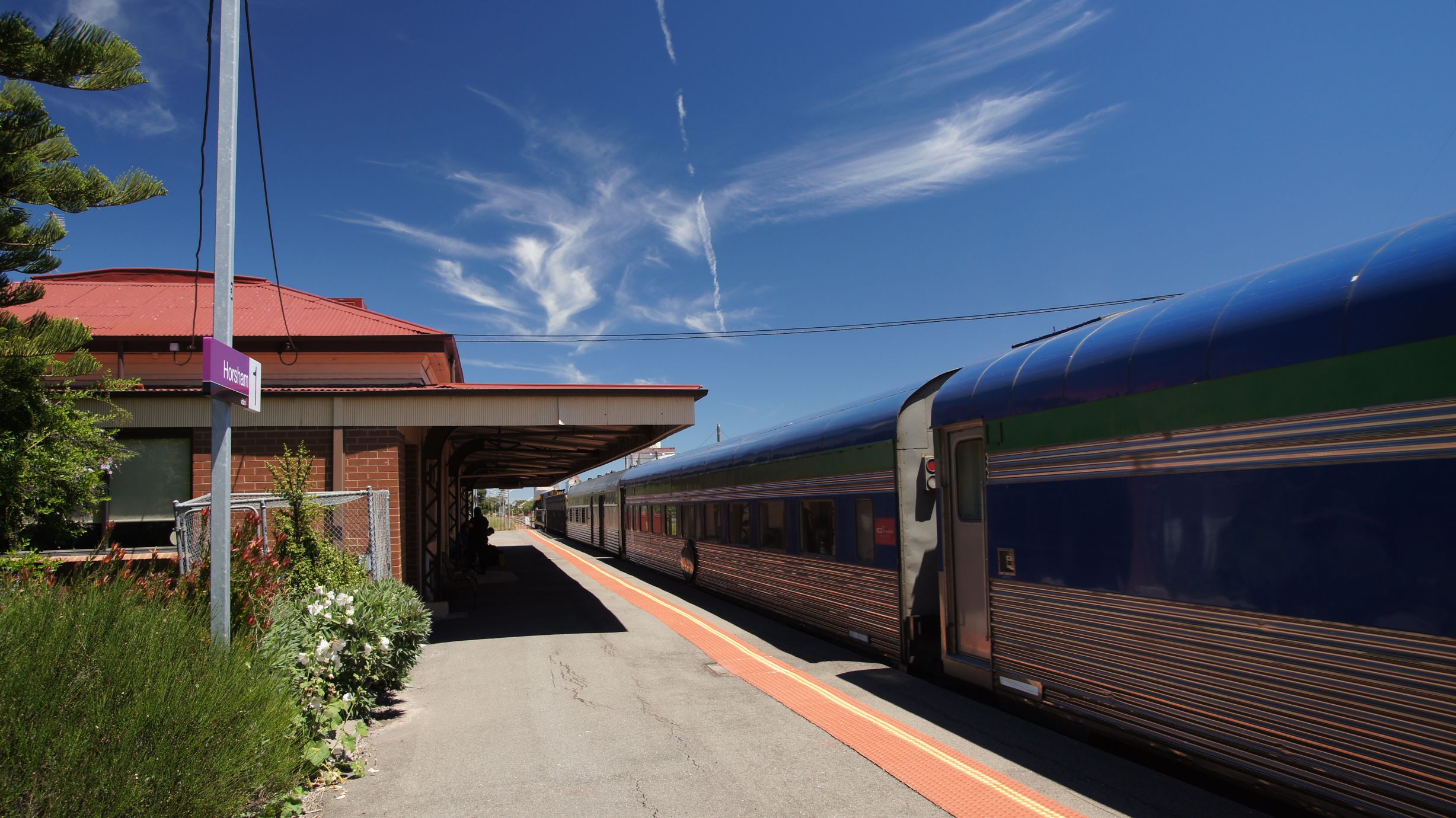
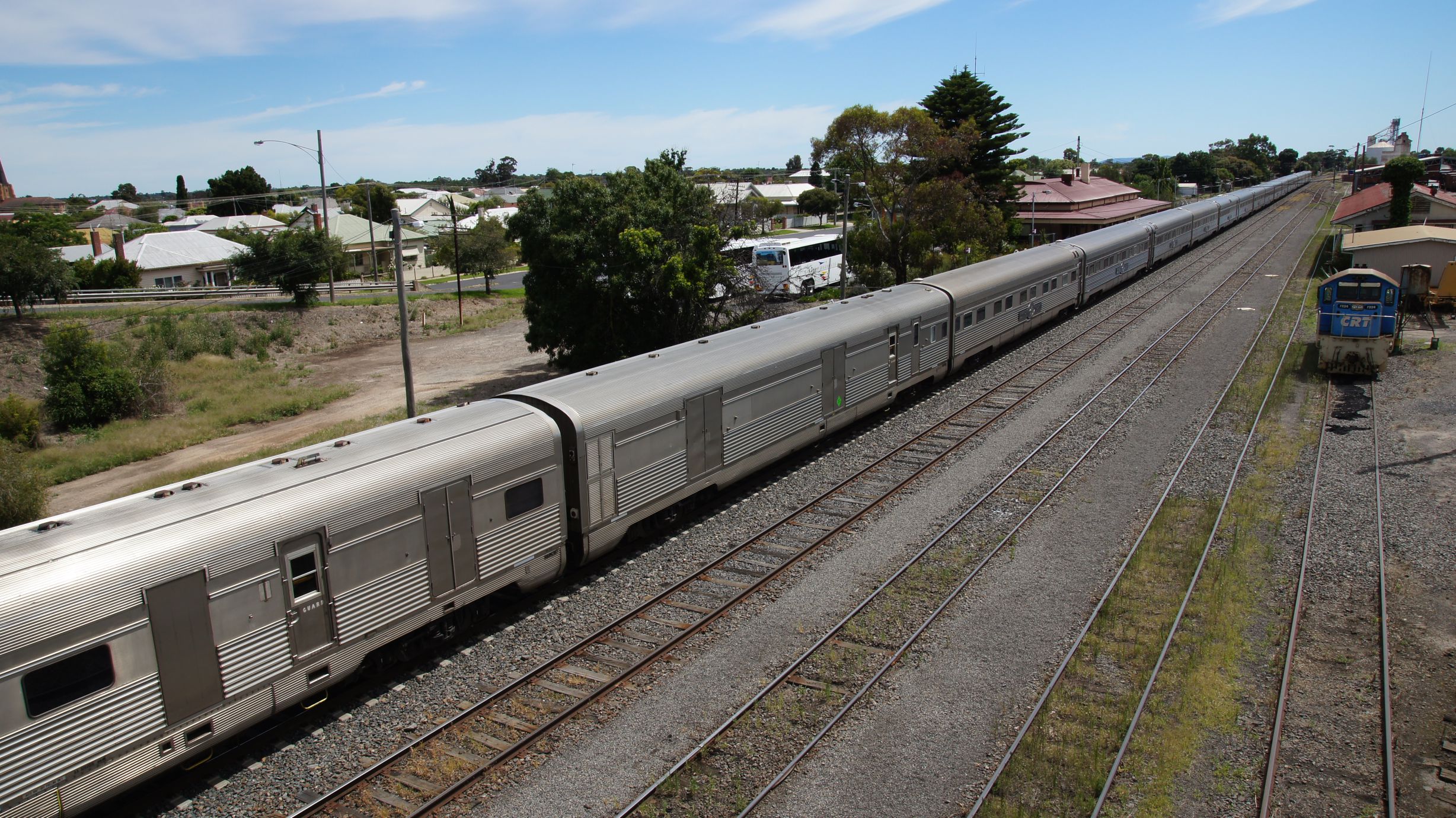
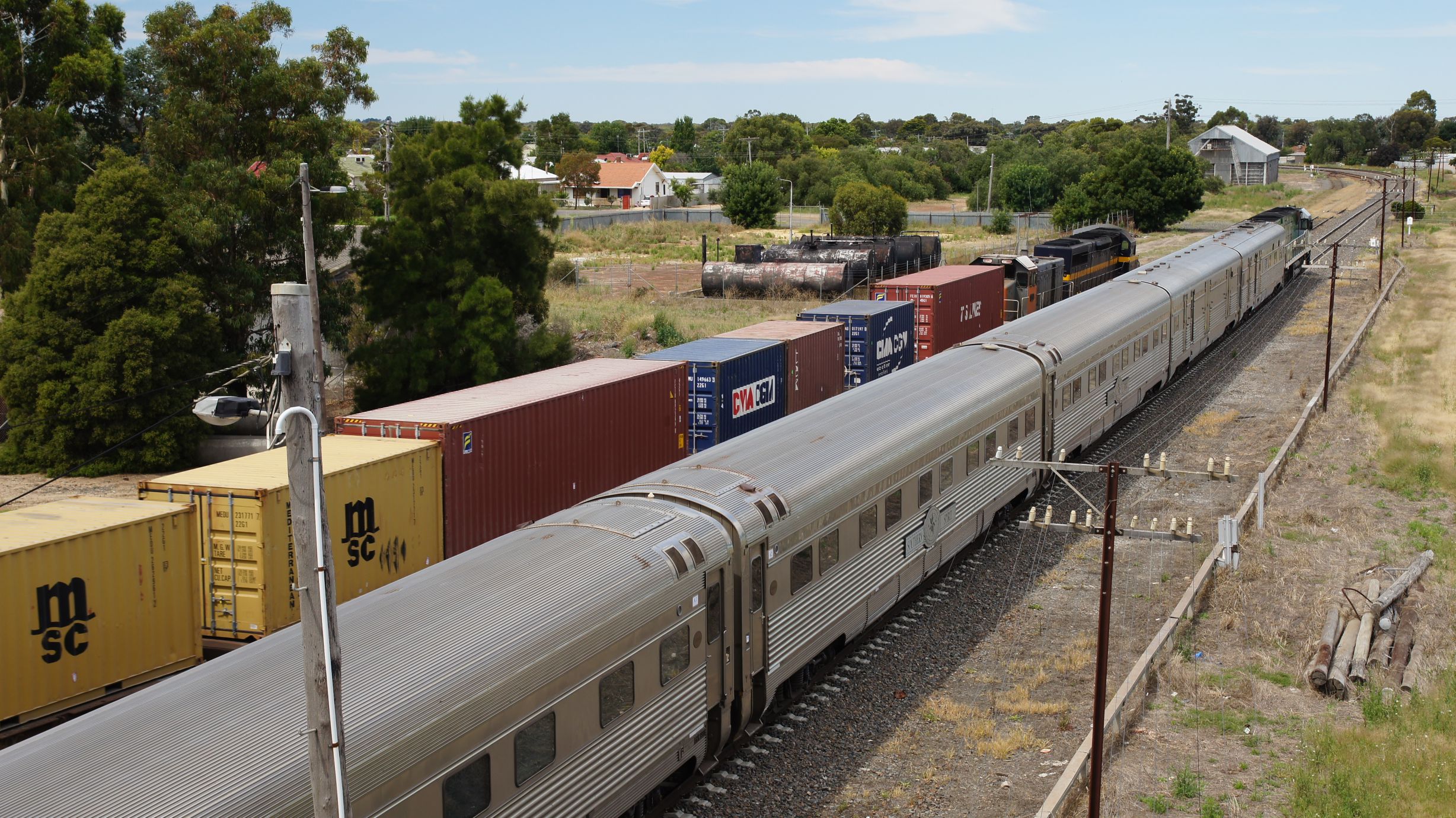
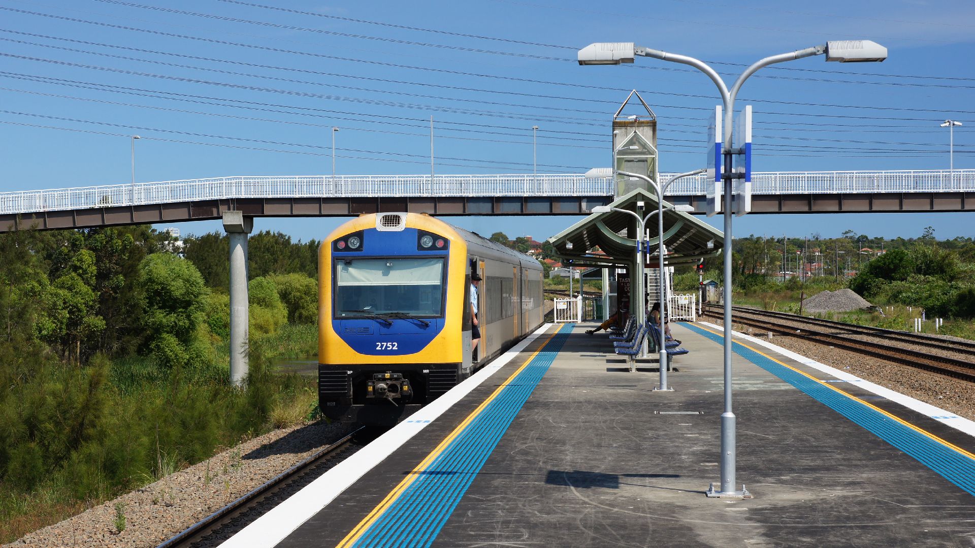
Horsham Station
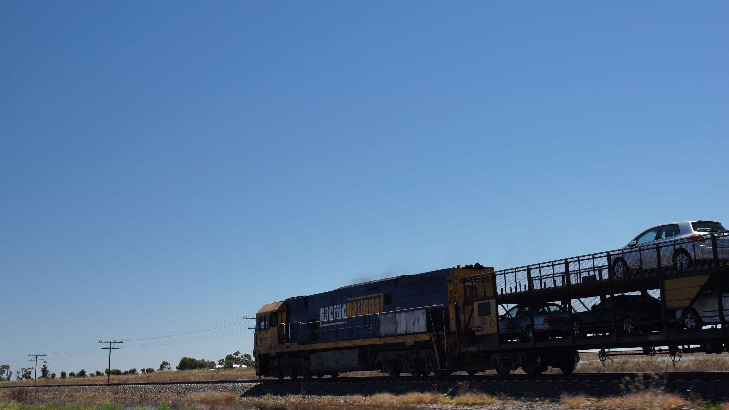
As we were arriving back in to Horsham, we saw the tail of the train... It was doing around 10km/h towards the first level crossing in the town which was still inactive. After hitting it's horn, the lights and bells started chiming and it proceeded further. Fortunately, we were doing 60km/h and easily made it to the station before it.
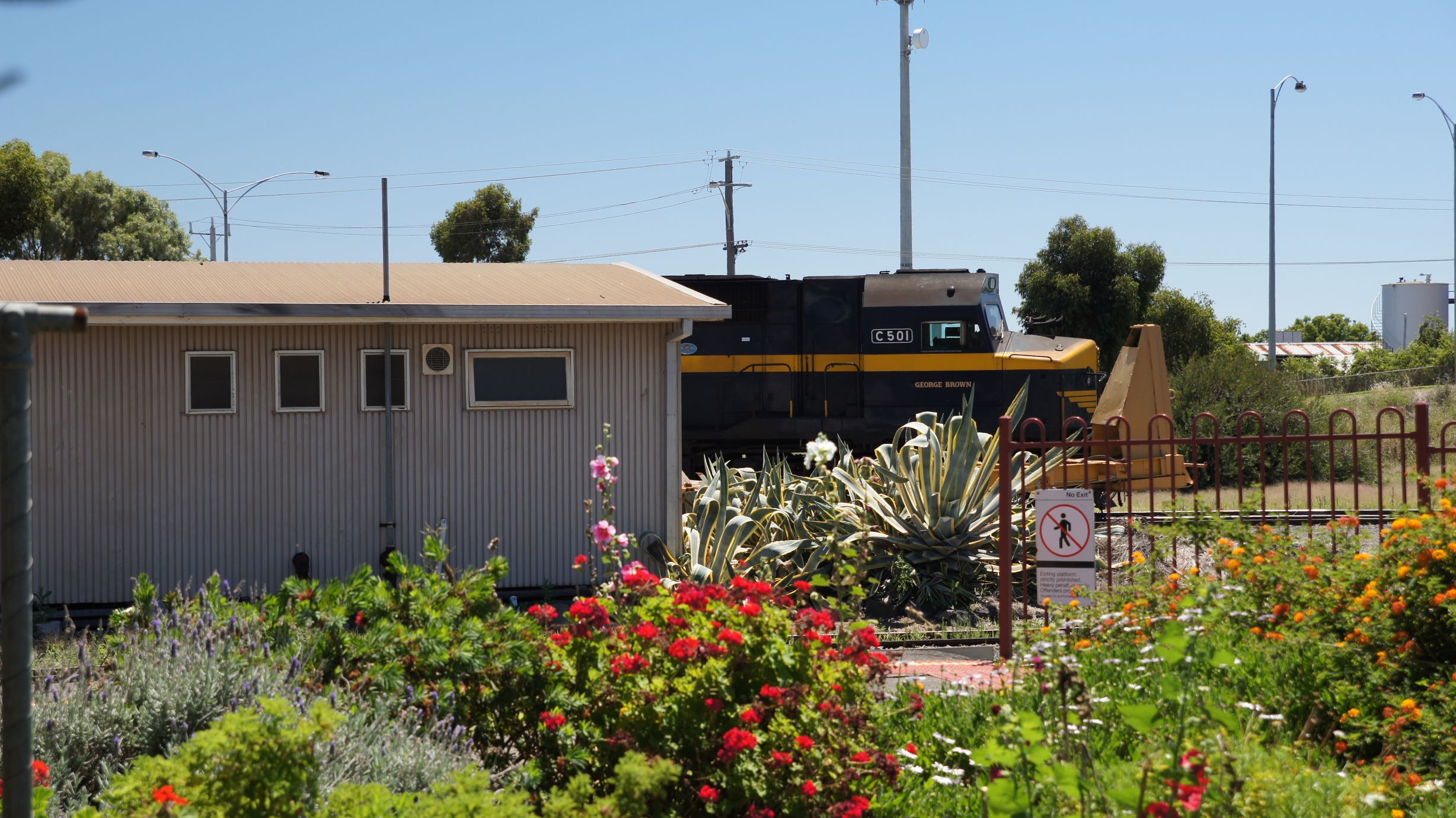
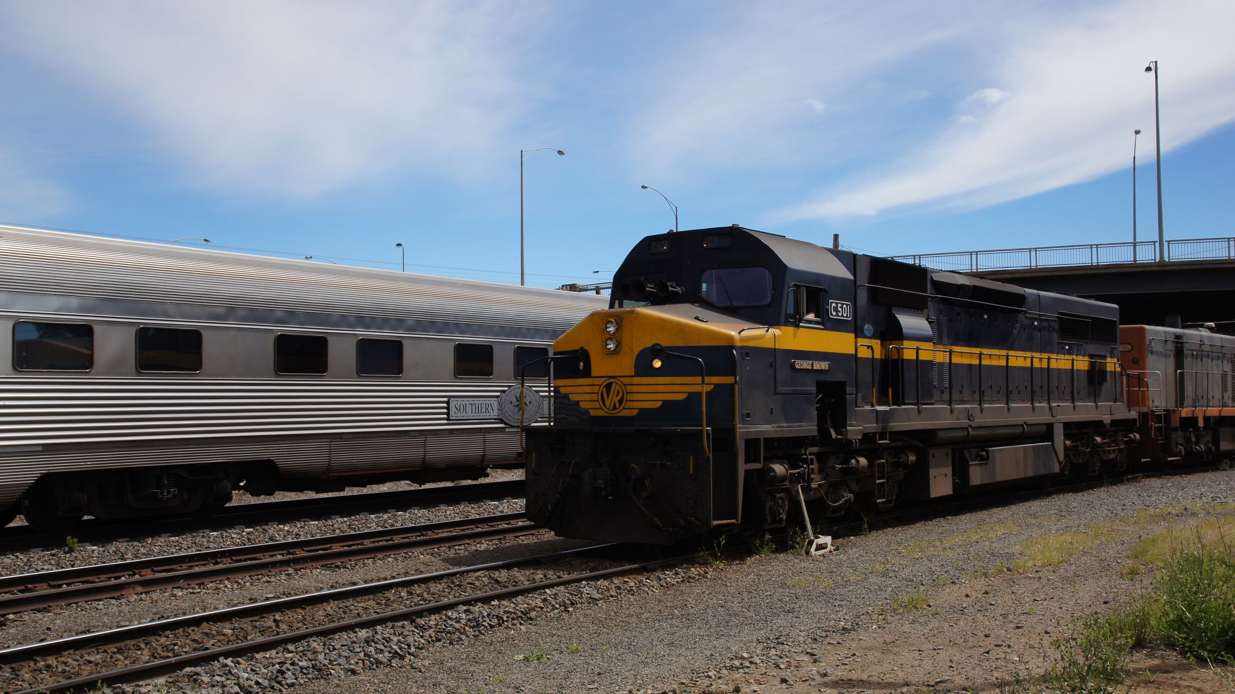
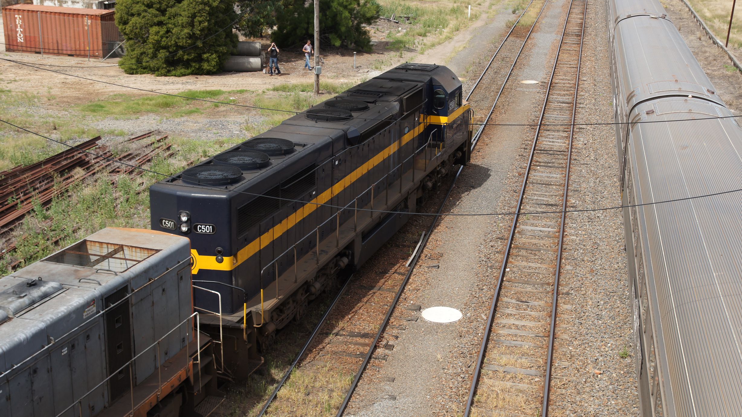
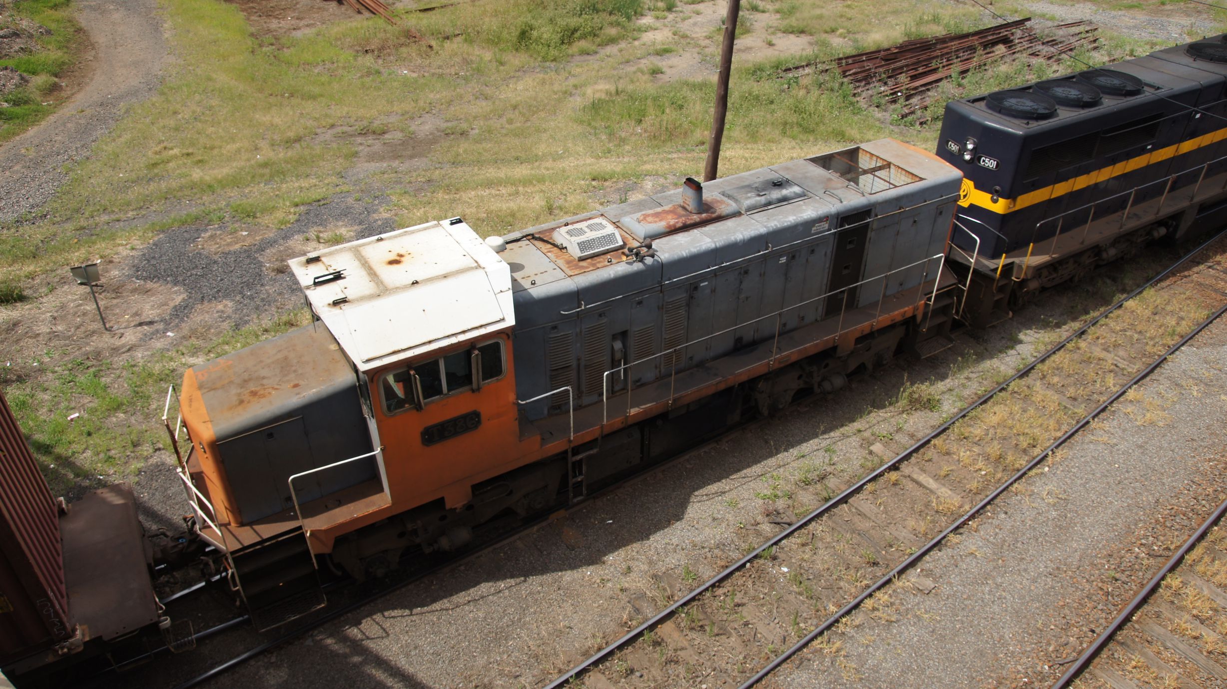
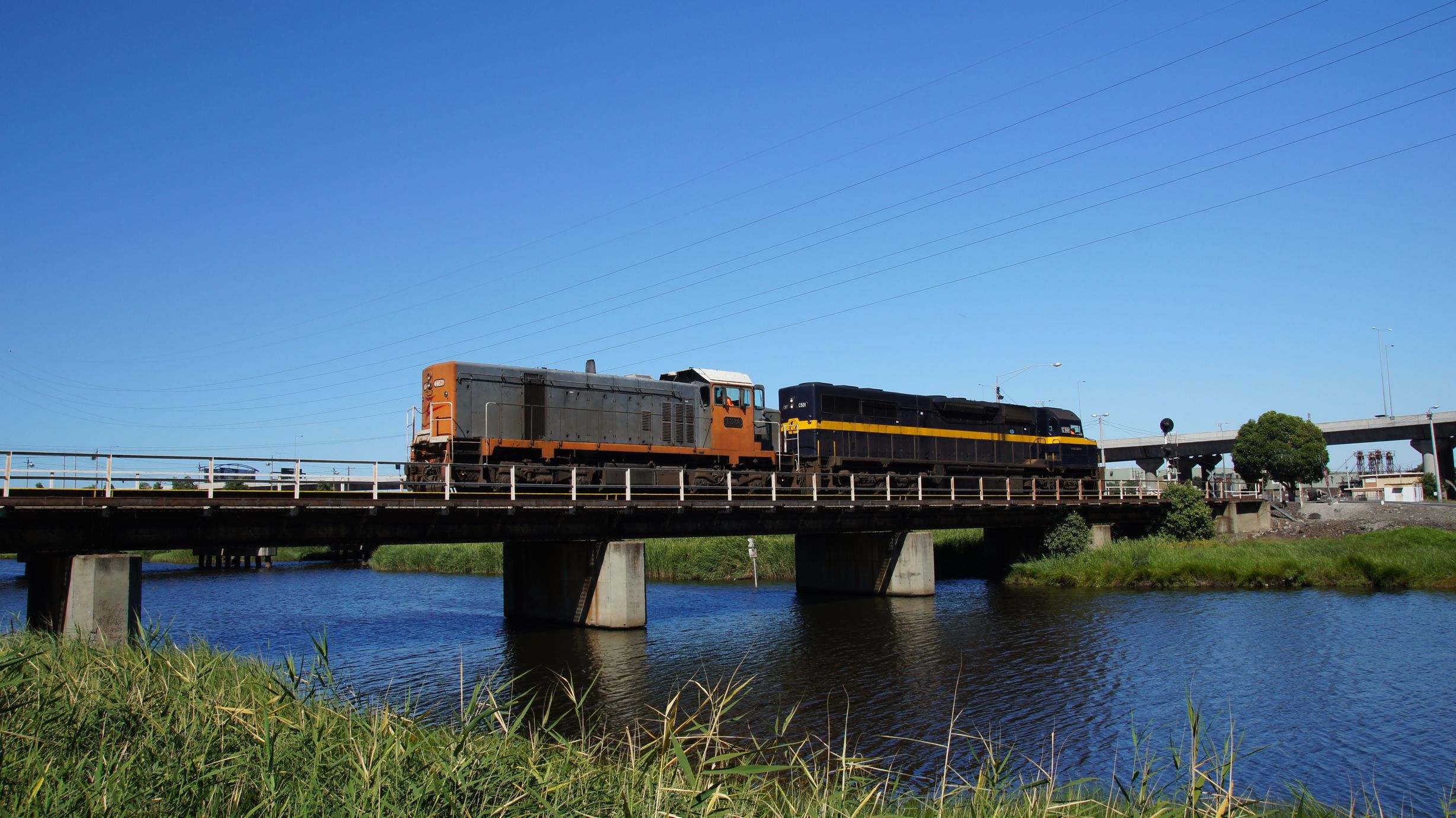
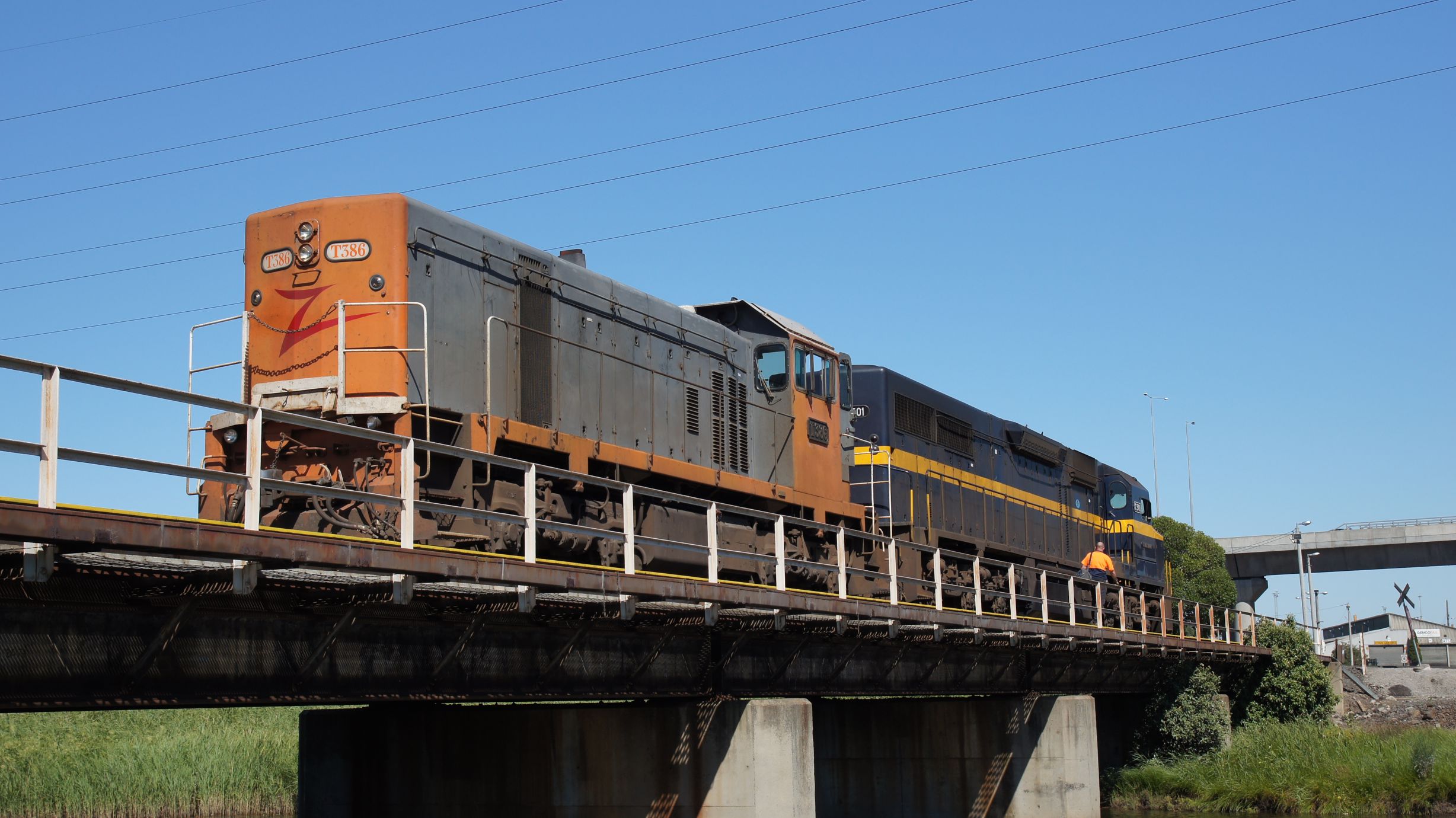
The train had to take two attempts to get everyone off. I believe I counted 16 cars and there was no way it would fit on the platform at once. There was an El Zorro grain train with T386 and C501 playing around in the container yards as well.
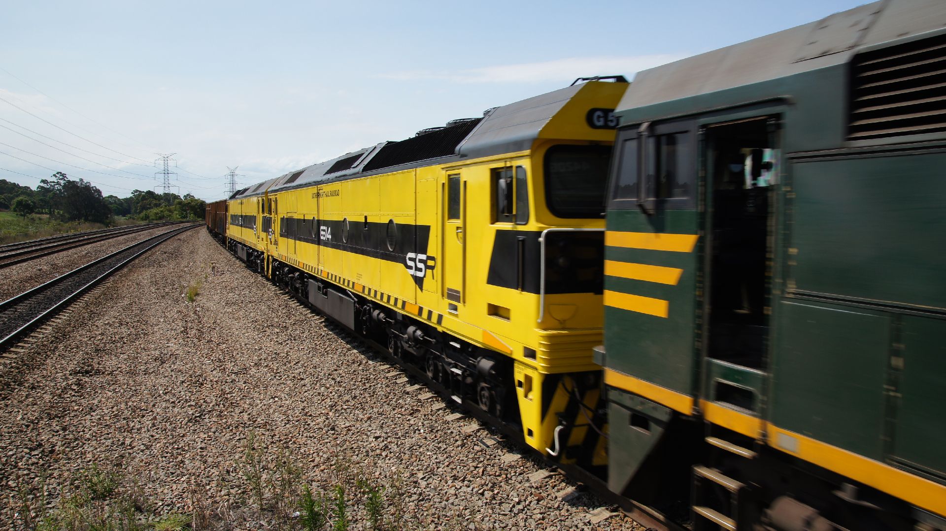
Horsham itself wasn't very photogenic and so we decided that Ararat would be a better option. The goal was also to find a line-side position somewhere along the way to get The Southern Spirit once again. Unfortunately the line deviates a long way off the beaten path and we gave up. We therefore also missed the west-bound container train (if it ran at all.)
After arriving much too early at Ararat, we decided that it was time to return back to Melbourne; we'd see the train again in the morning.
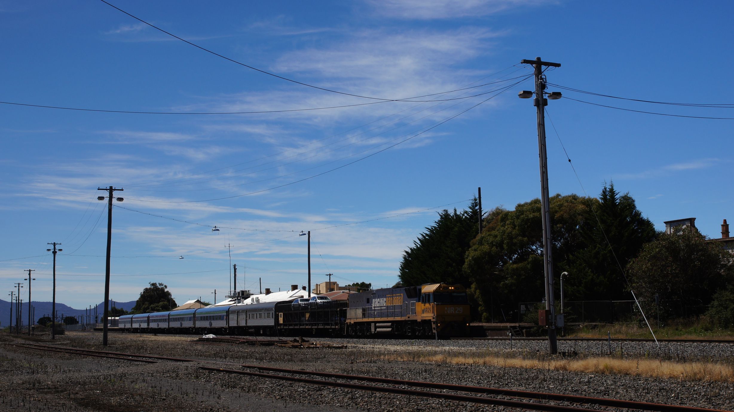
The Southern Spirit in Melbourne
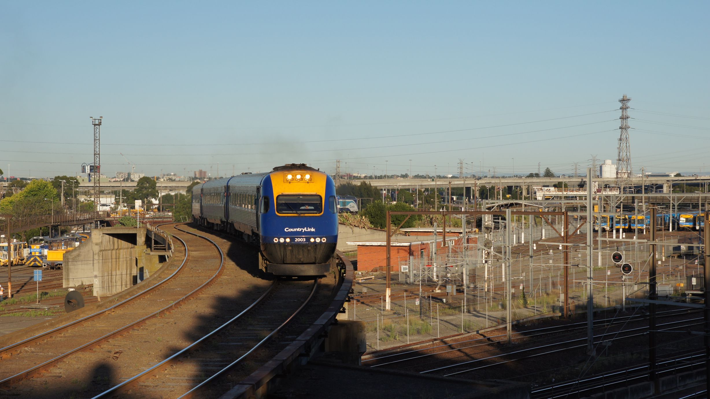
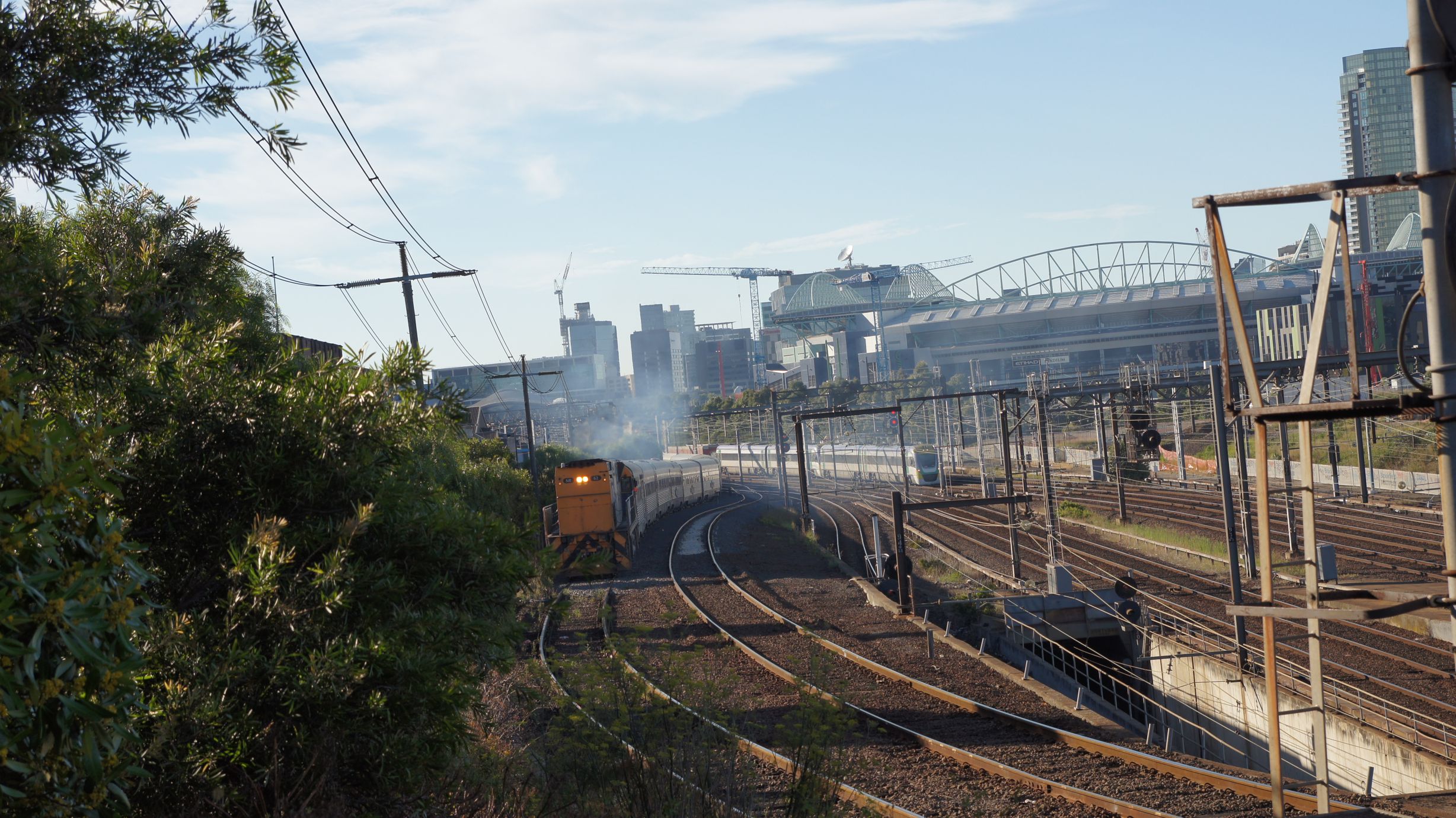
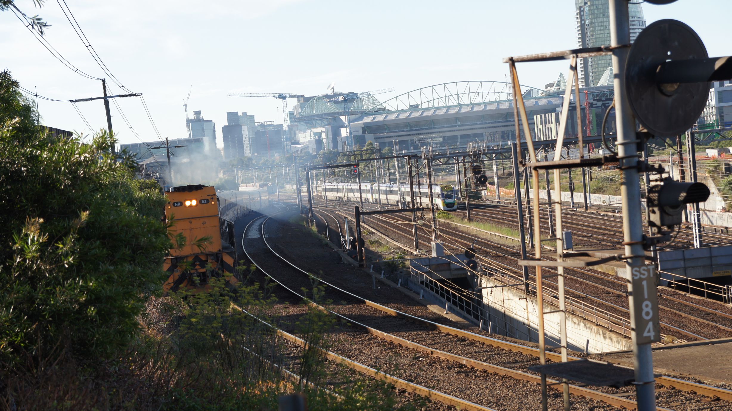
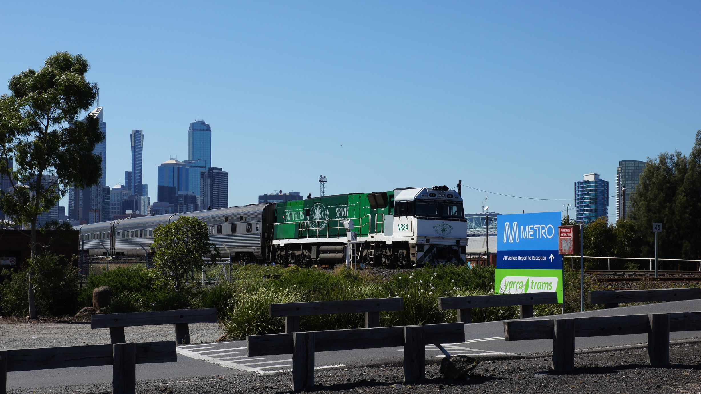
I assumed my usual position at the North Melbourne flyover and met a few new people who were also waiting for the same train. The XPT arrived on time and then the Southern Spirit arrived, attached it's pilot loco and then proceeded to Southern Cross Station.
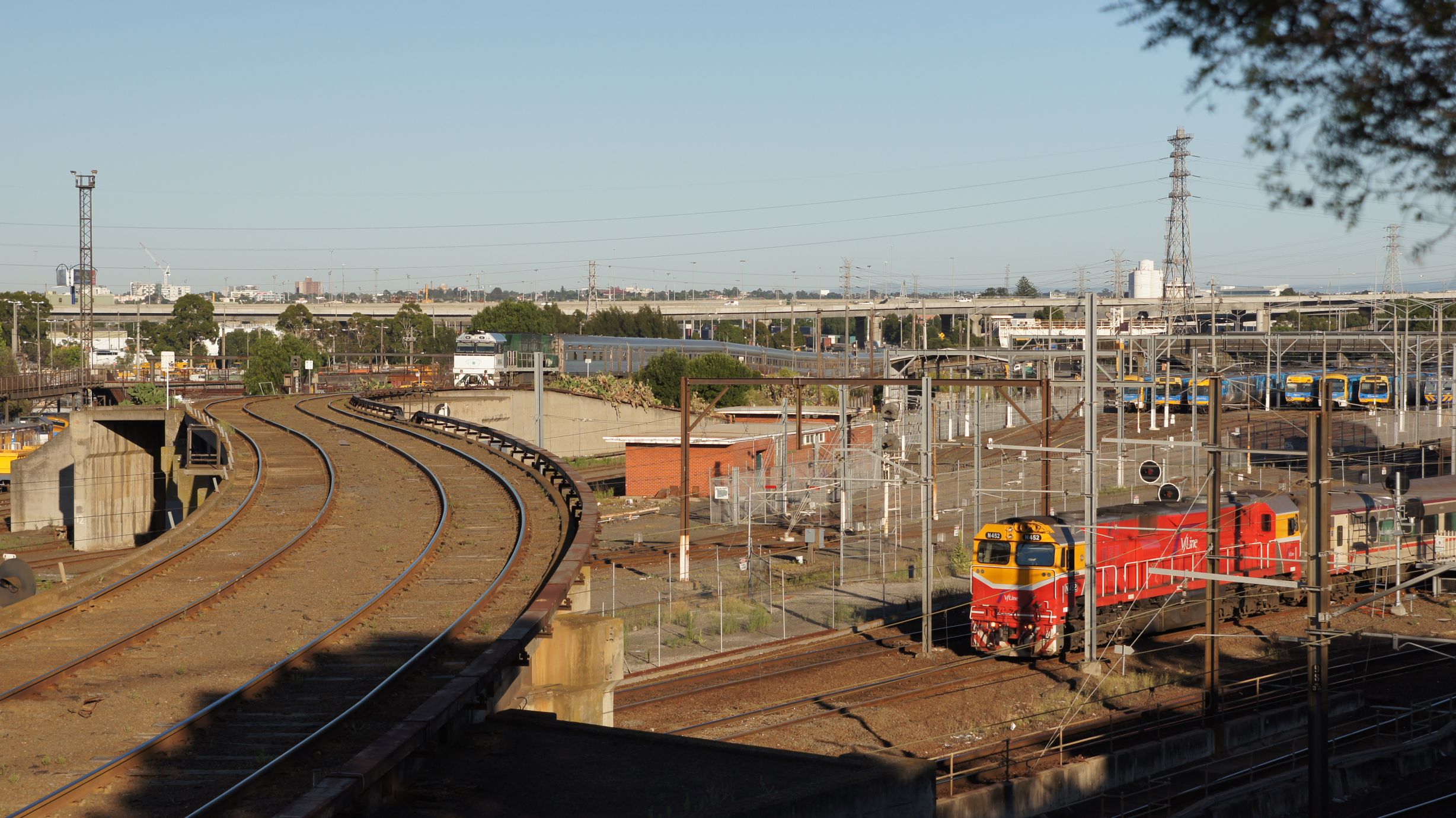
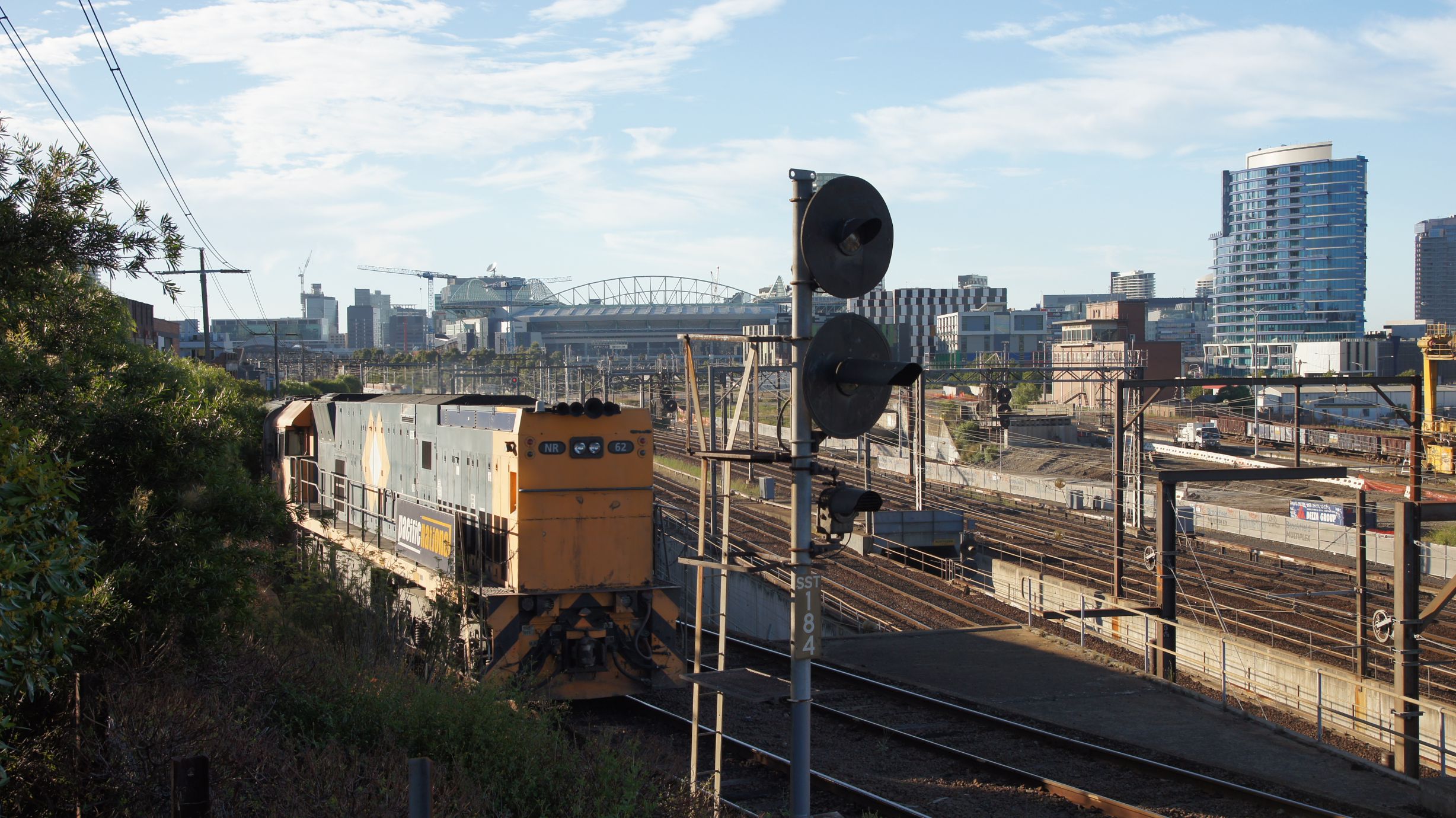
The consist then made its way back to the freight yards after dropping the passengers off. The pilot loco did all the work here over the flyover. The XPT also started its return journey to Sydney.
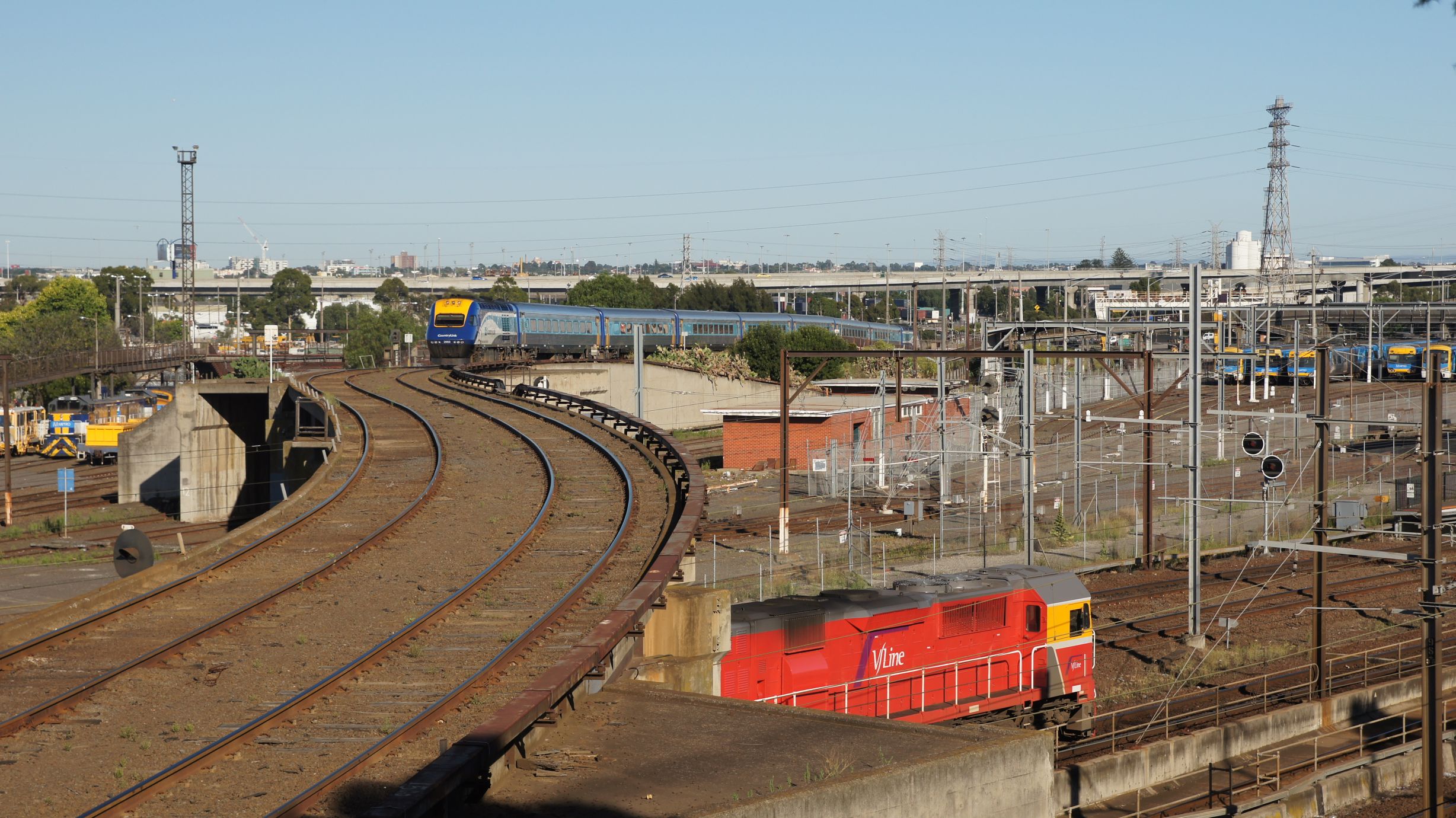
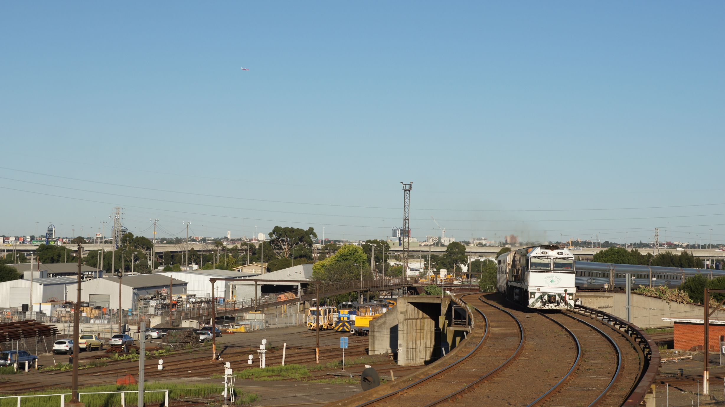
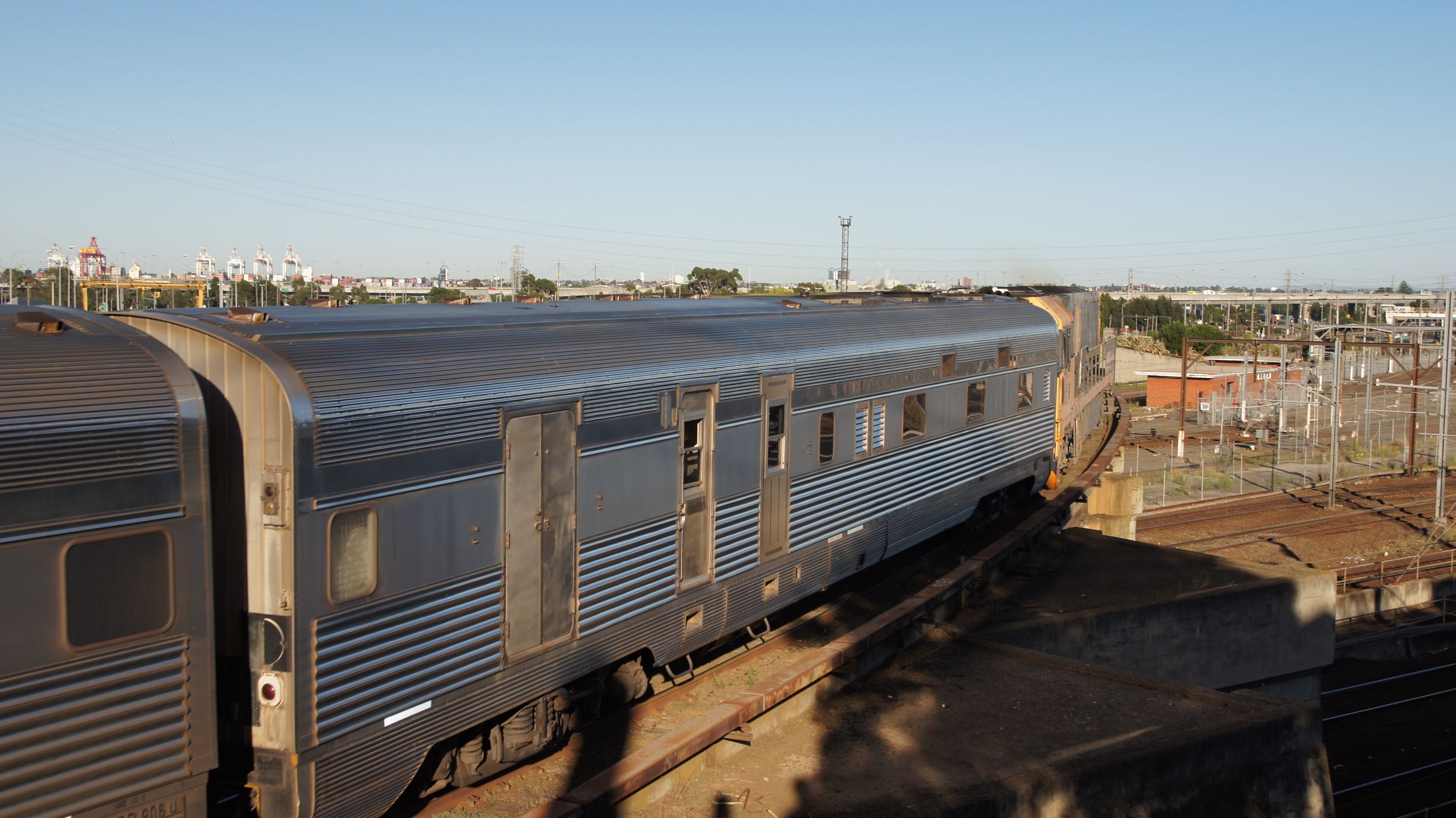
The consist then sat in the freight yards for around two hours. I had enough time for breakfast and then returned to the Canal Sidings to watch it come back into Southern Cross.
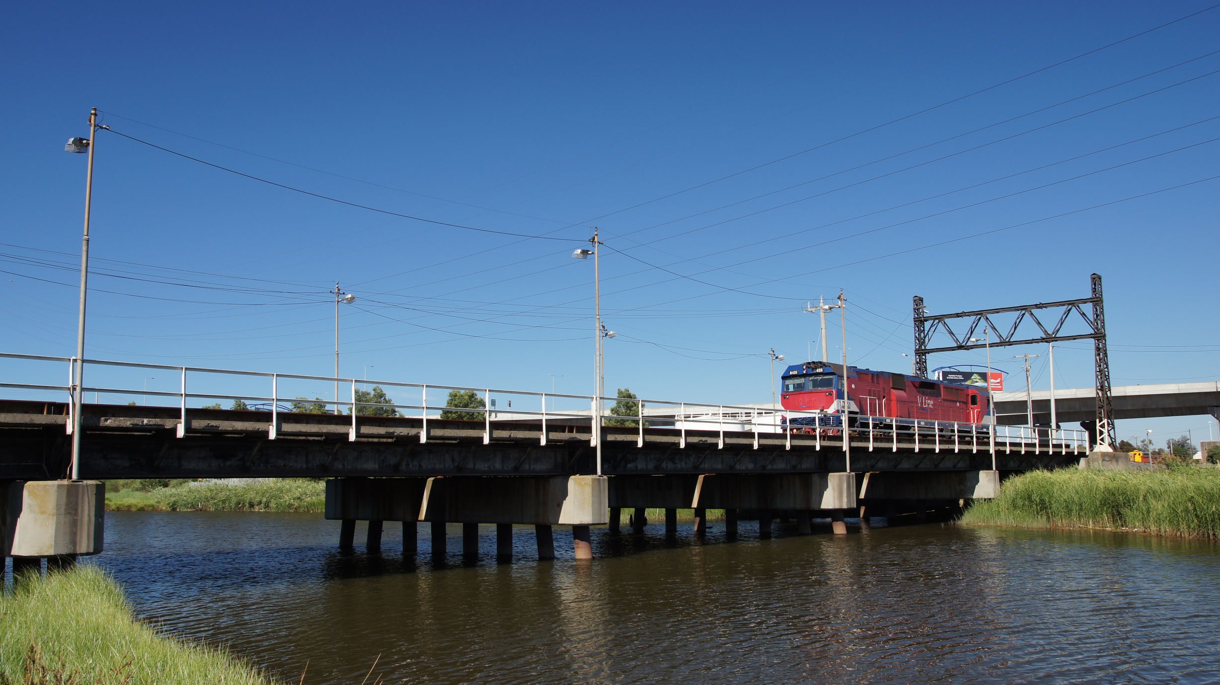
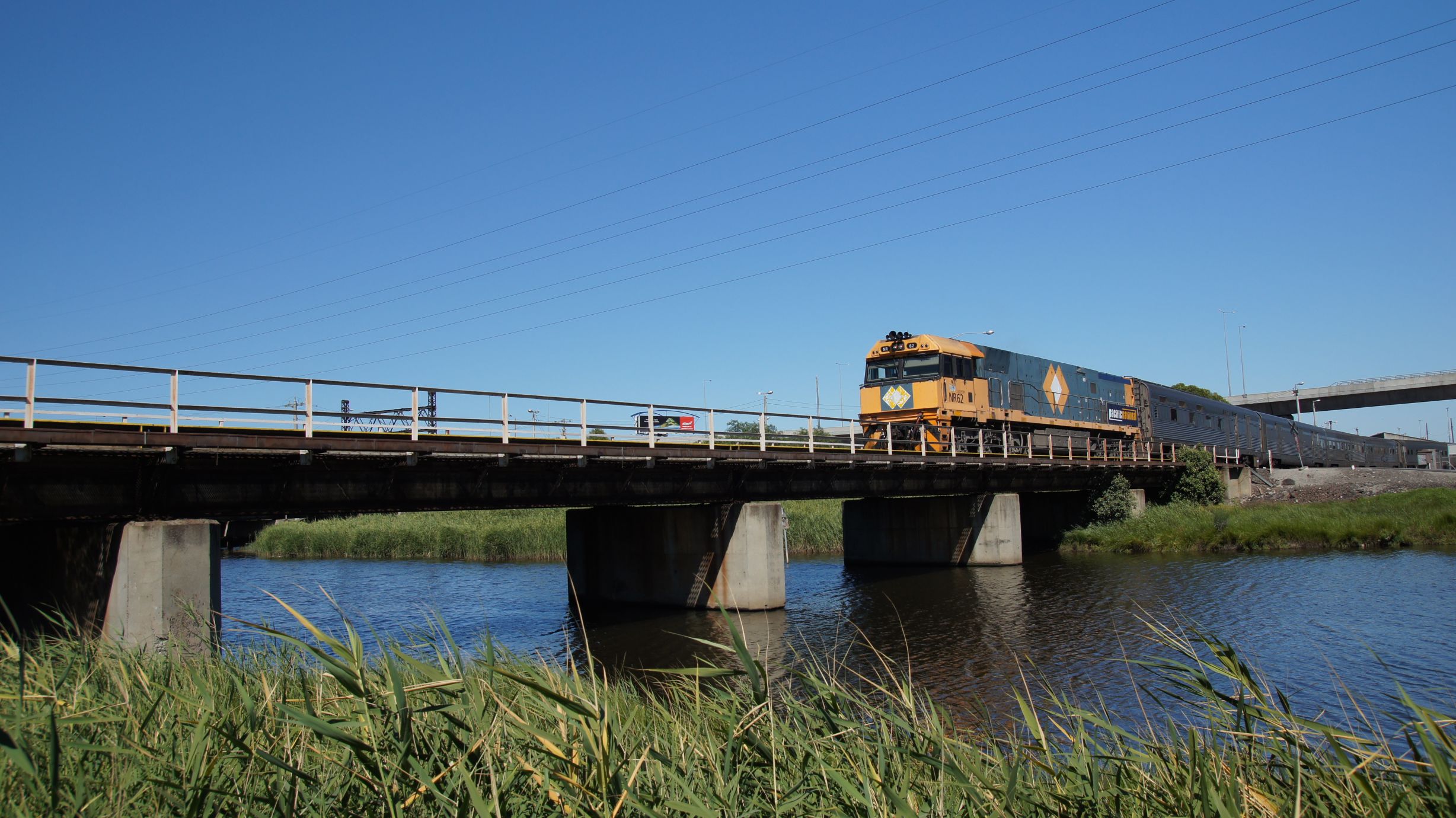
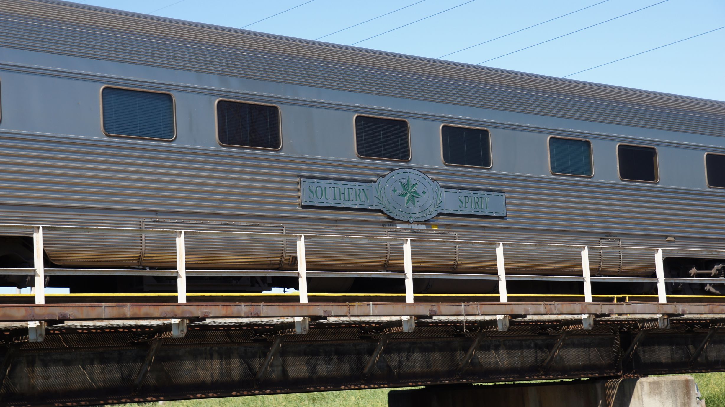
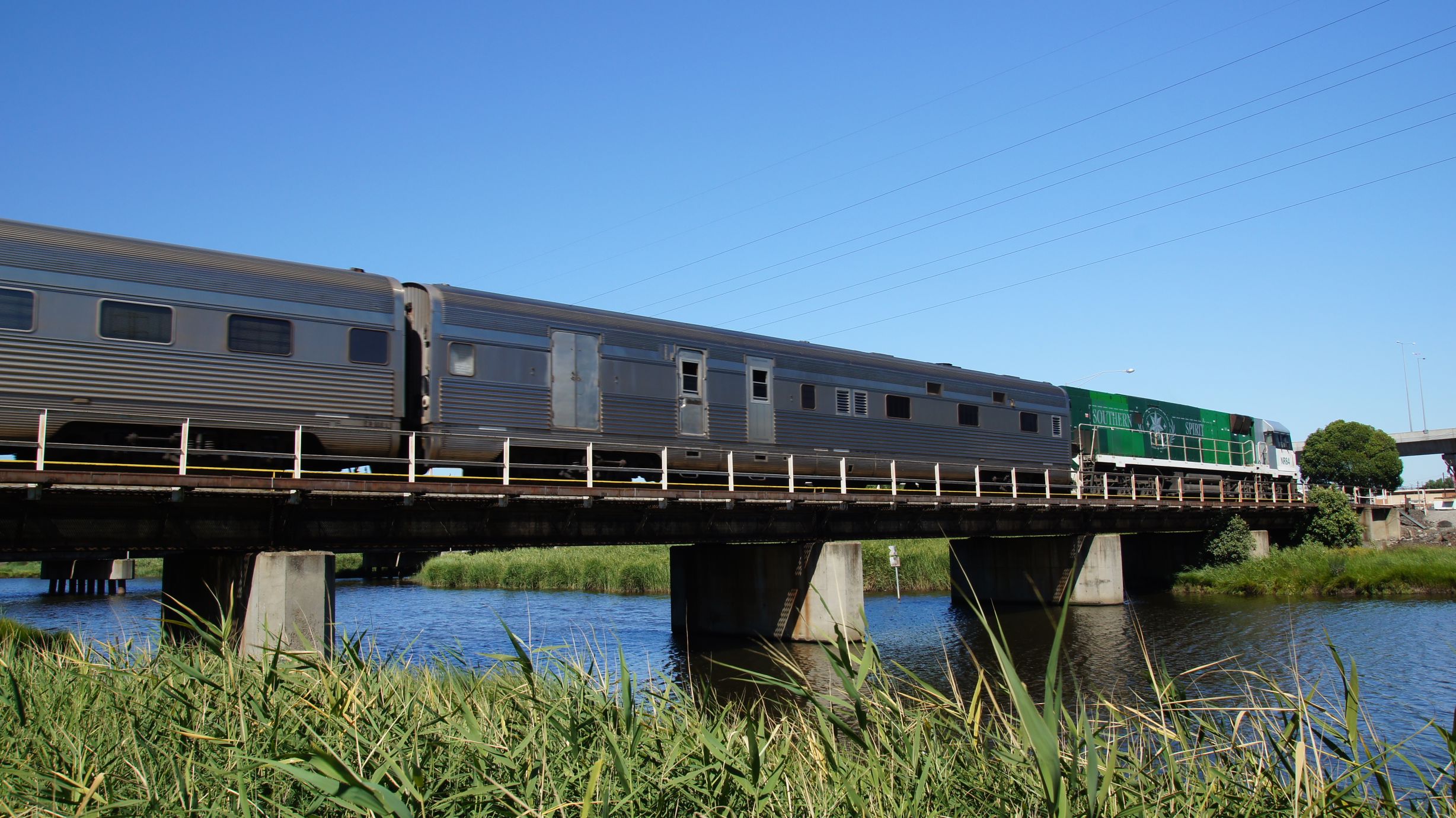
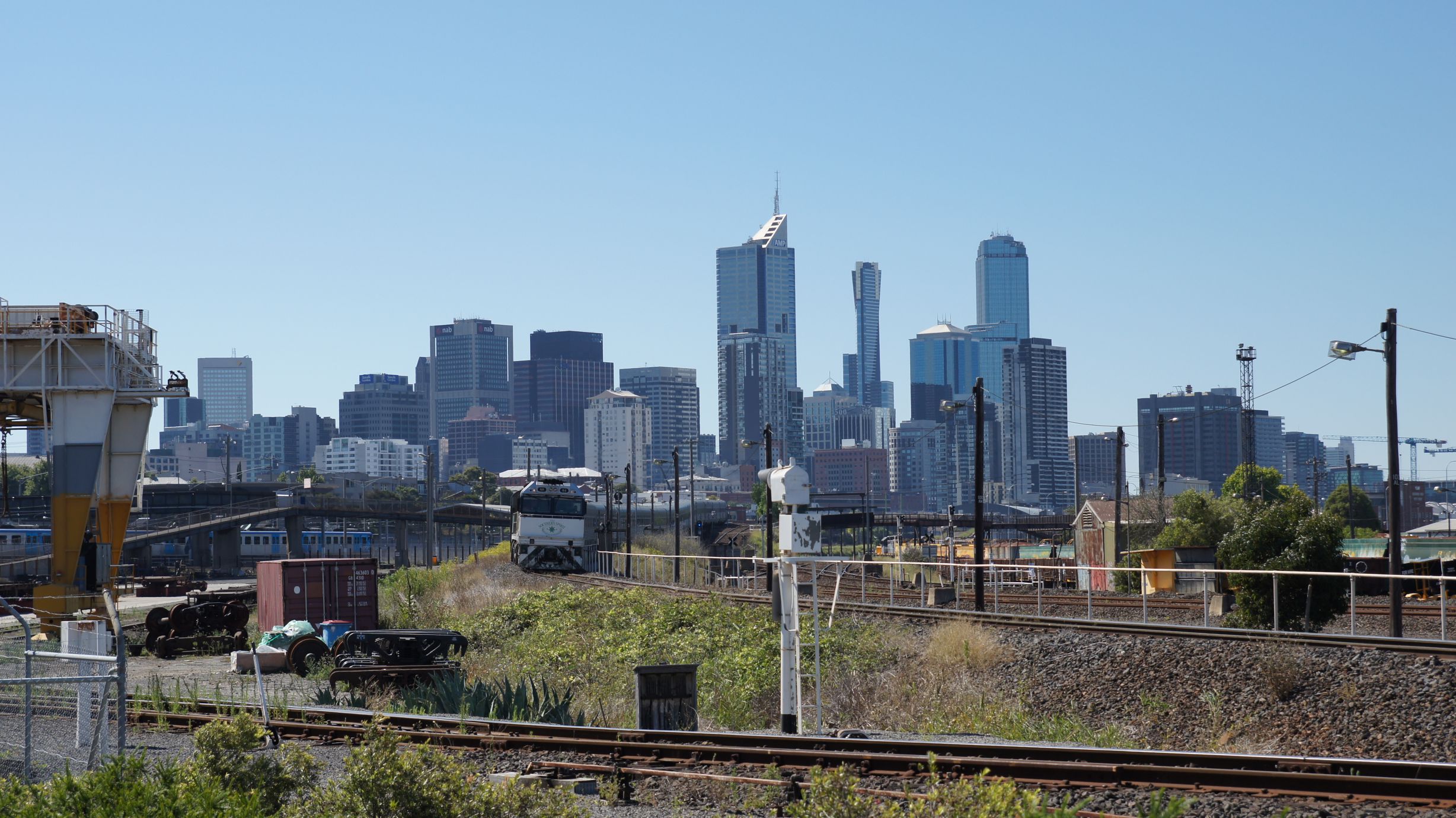
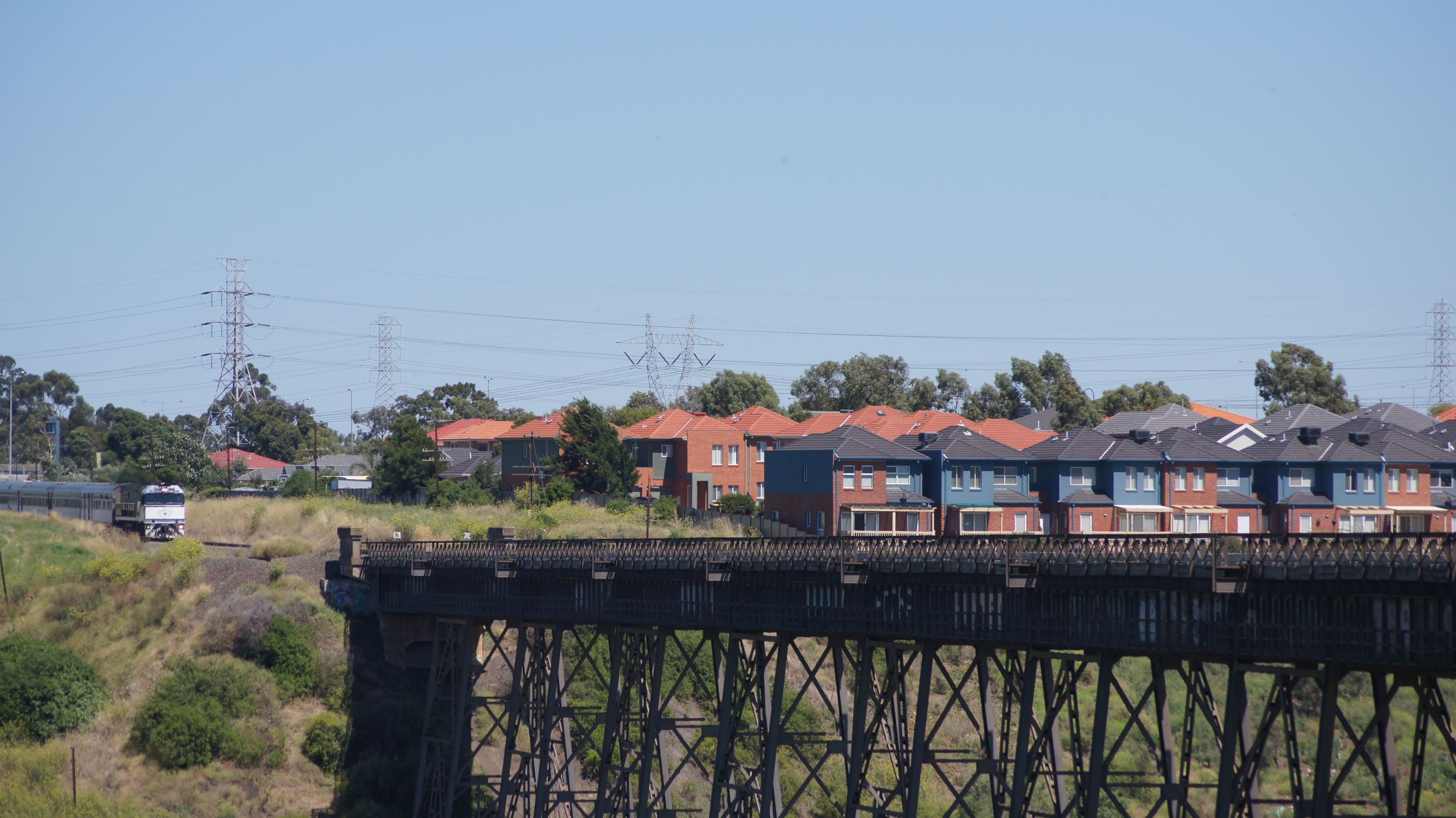
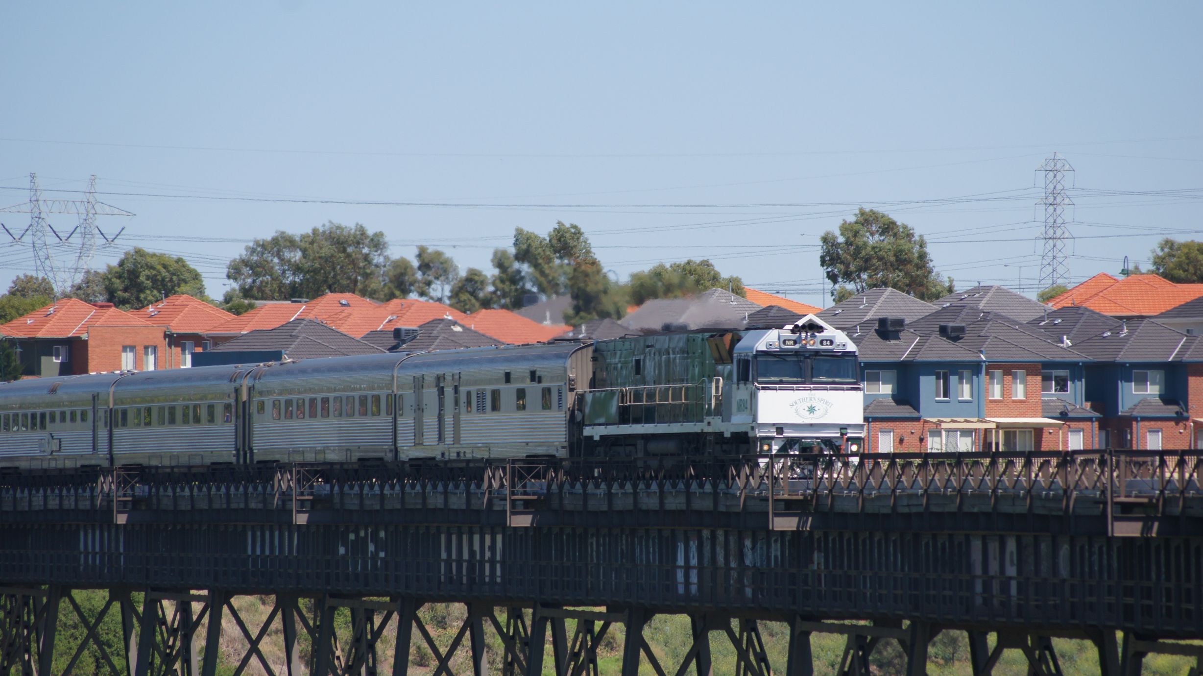
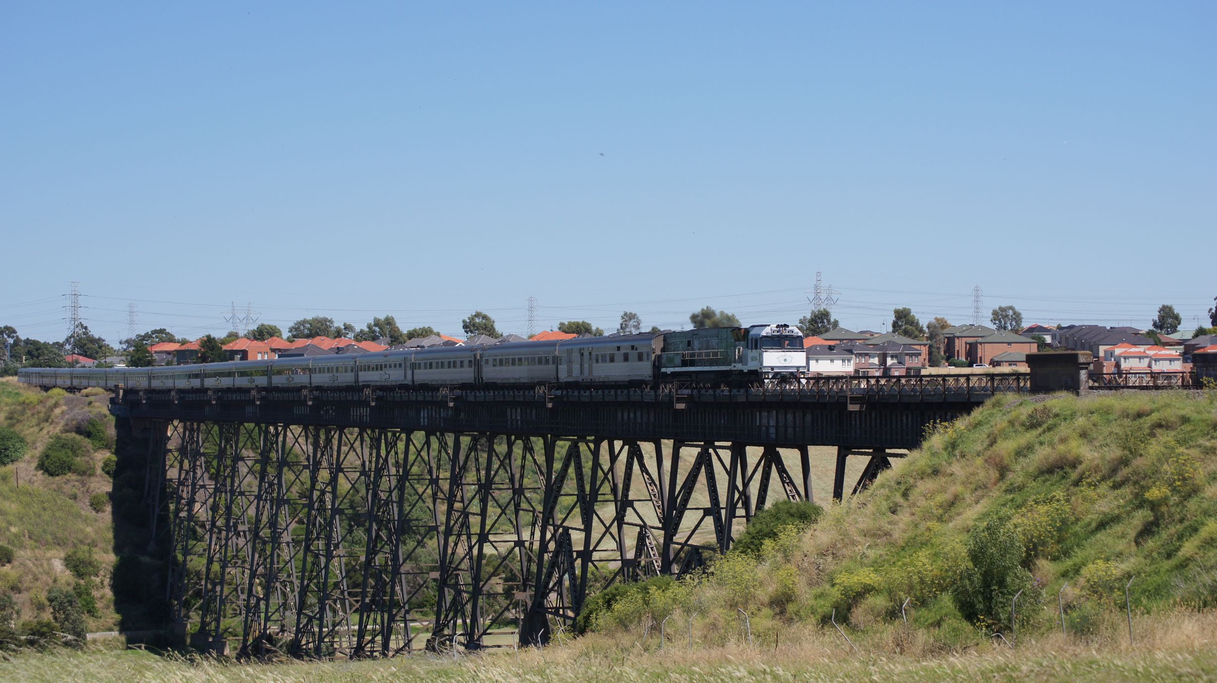
The final trick then was to get out to the bridge over the same "Railway Canal" near Jacana. This should have been an easy shot but I chose the wrong lens again. Either way, it was a great way to end the chase.
The Southern Spirit will return via Melbourne and be at Southern Cross at around 7pm on Tuesday the 8th of February. The pilot locomotive will be attached at the same location but will be detached well out of town. This will be well worth a photograph or two and I'll attempt to get them next week.
The whole journey from Adelaide to Brisbane and return is also to be repeated, starting on the weekend of the 12th and 13th of February. I'm not so sure if I'll cover the 1000km again, but you never know, there might be other interesting things to see in the area.
Chichibu Railway – September 2010
An apology: I'd traveled here last year whilst in Japan and had completely forgotten to write up the experience. Hopefully I haven't mis-recollected too much of the following information :)
I'd seen the freight operations in Chichibu online in multiple places, but wanted to go and check out the 'rolling museum' for myself; it was one of the many private railways that I had intended to visit and one that I had the freight timetables for.
The Chichibu Railway
The Chichibu Railway (Official site, Japanese only) is a private railway in Japan which runs west from Hanyu Station to Mitsumineguchi Station via Kumagaya. The railway operates both passenger and freight (limestone) services. It's rolling stock consists of many handed-down locomotives and multiple units.
Getting to Chichibu from Osaka
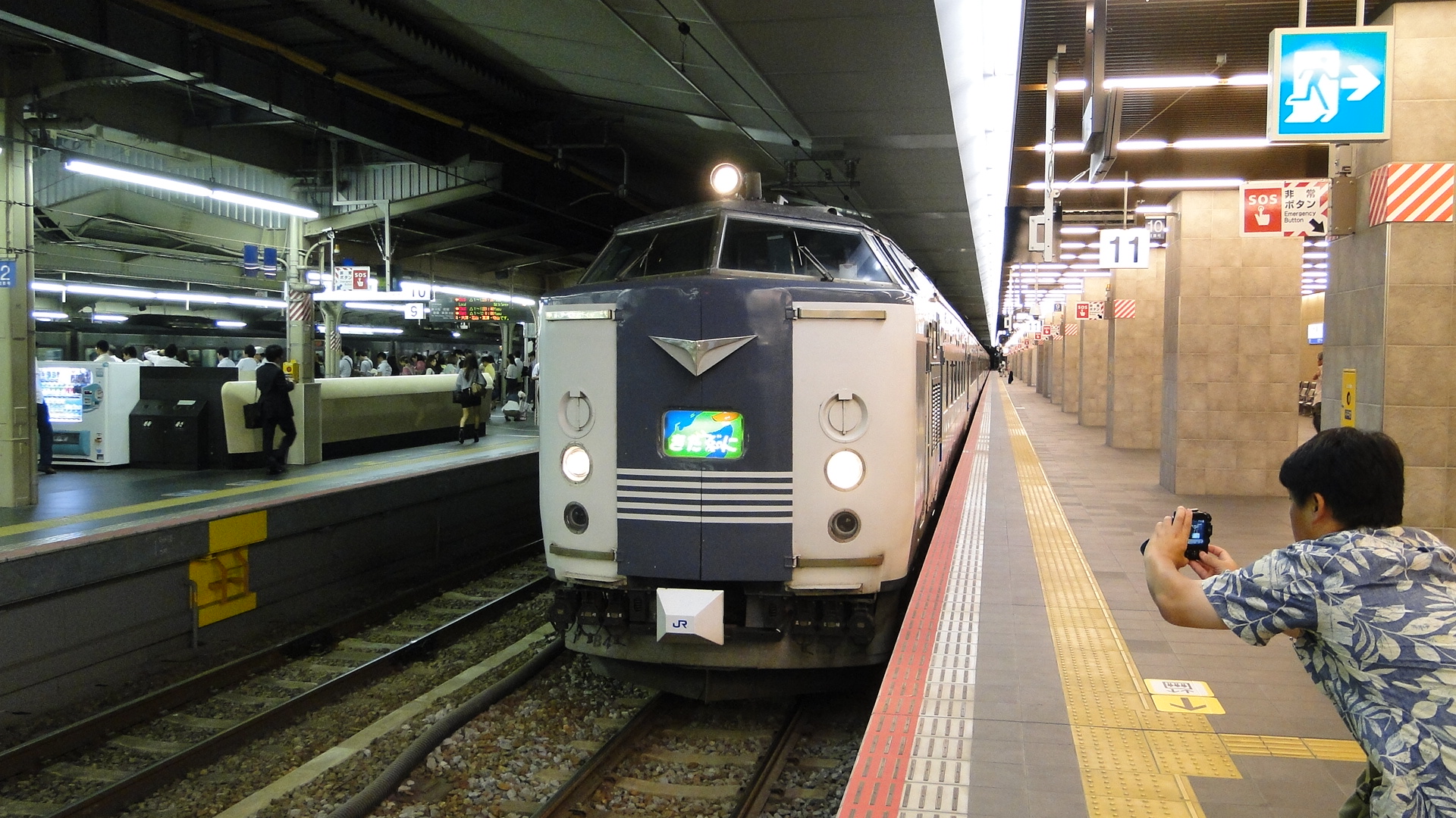
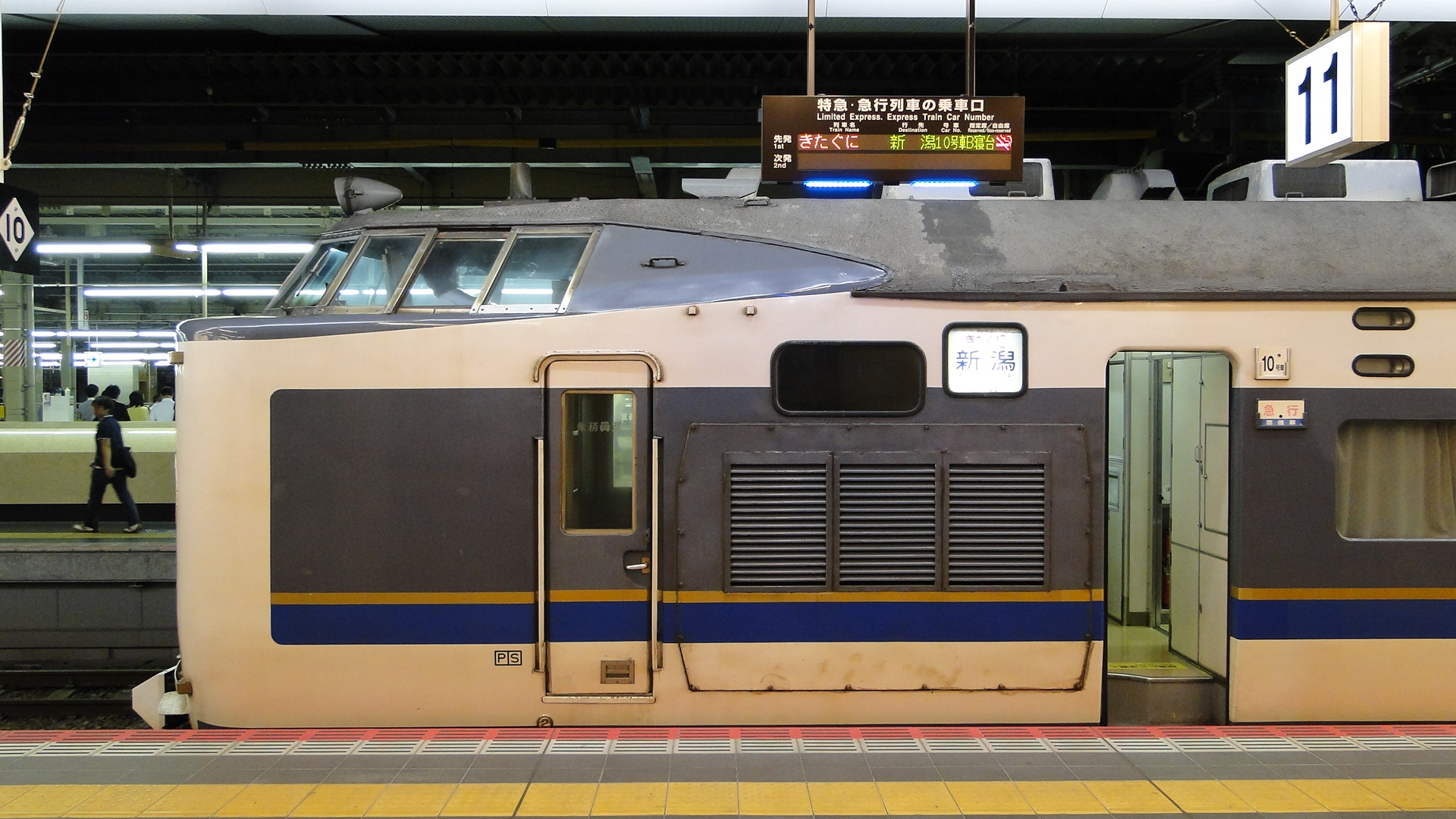
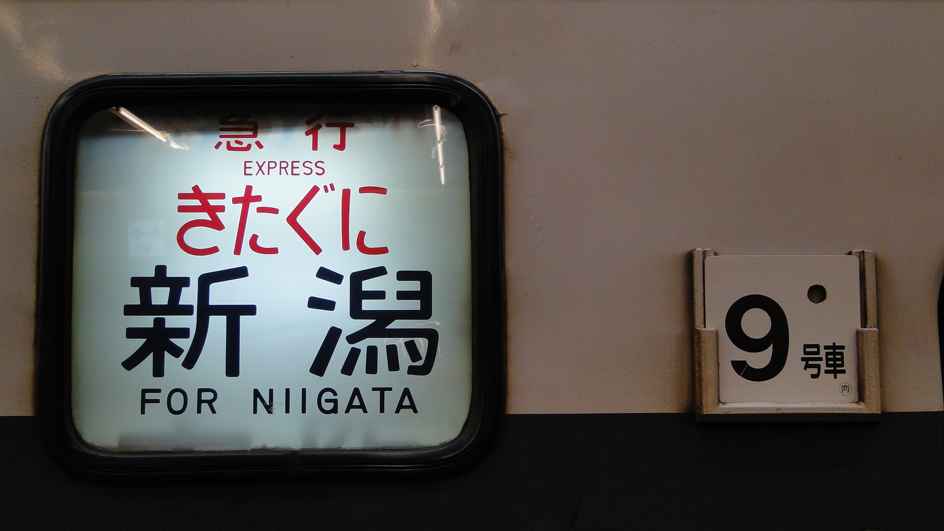
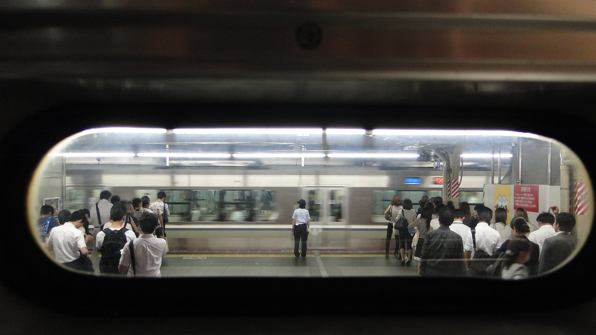
Since I'd been visiting friends in Osaka, I wasn't in the best location to be getting to Chichibu early enough for some of the freight operations. Fortunately, Japan still has quite a few overnight services and one of these, the Kitaguni, would get me to Nagaoka in time to transfer to the Shinkansen to Kumagaya.
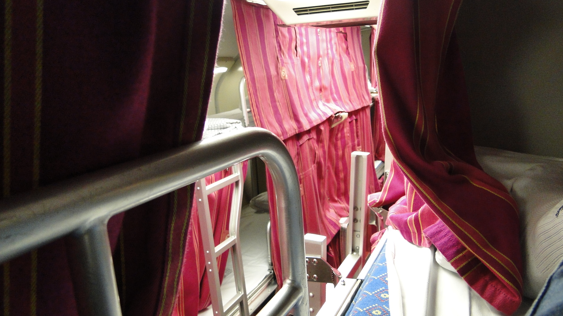
The Kitaguni departs Osaka Station just before 11:30pm each day and arrives at Niigata just before 7:00am the next morning. The service is operated by dedicated 583 Series EMUs and has multiple types of sleeping accommodation. I chose the cheapest bed, but I don't recommend this. See the photo below; I was in the top bunk and you get only a single peep-hole for a view.
Nagaoka to Chichibu
We stopped at Naoetsu Station briefly on the way through to Niigata. I grabbed a few photos before we continued on to Nagaoka.
At Nagaoka Station I transferred to the next southbound service to Kumagaya. I had breakfast at the station and then found the Chichibu platforms downstairs. Tickets were purchased from a vending machine and I chose to travel to Takekawa. This station is west of the branch that runs to the Taiheiyo Cement Factory and is the first place to see traffic heading east-bound.
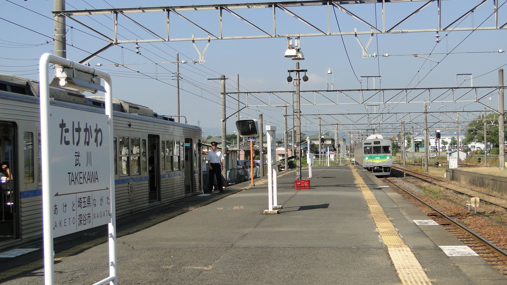
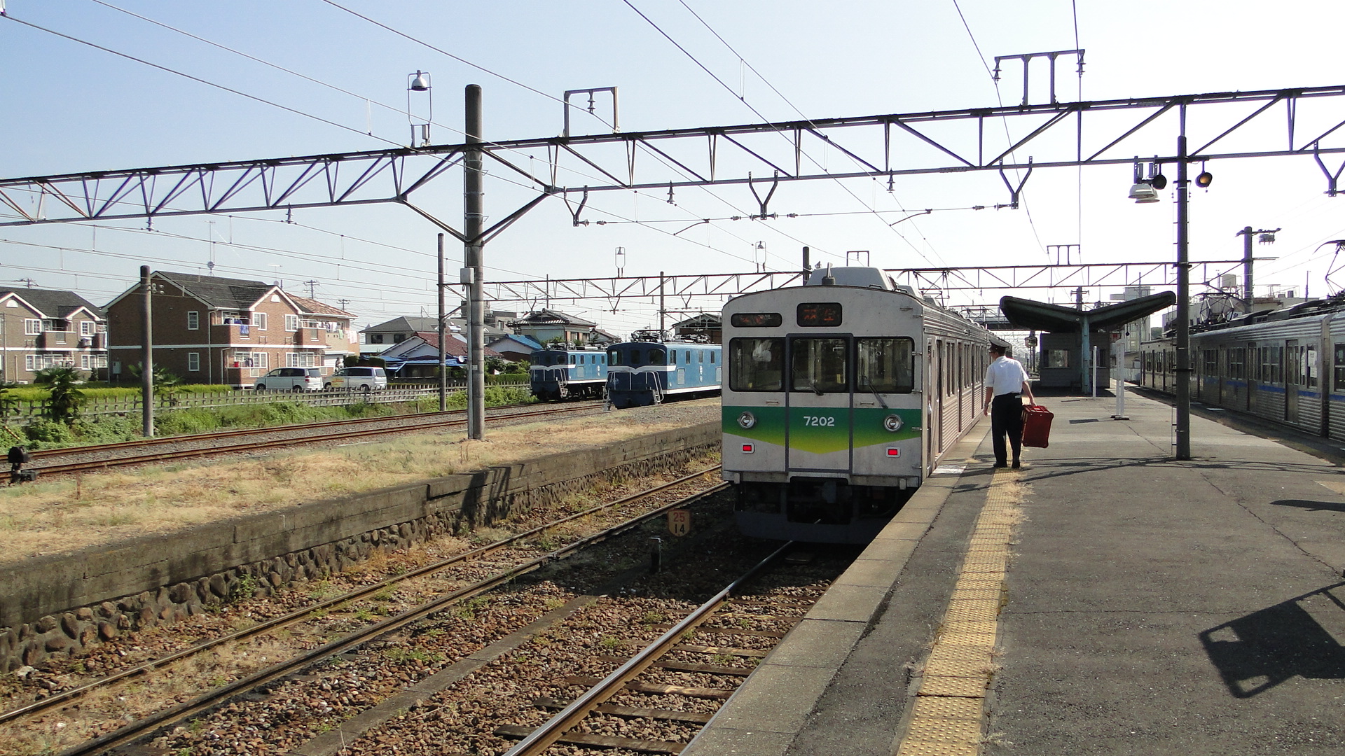
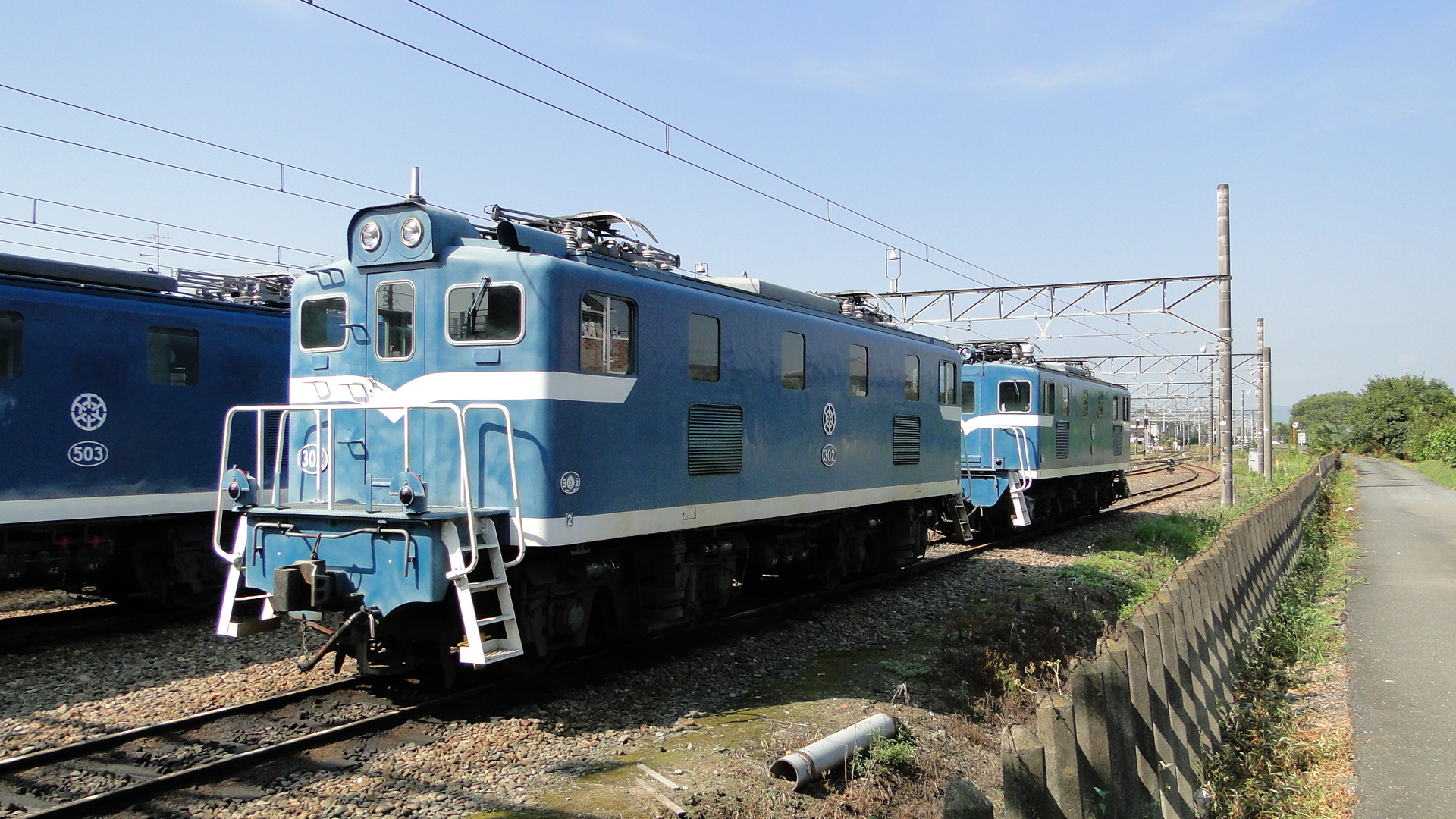
Upon arriving at Takekawa I found several of the electric freight locos stored in the yard. This was to be an ominous sign, as it seemed most of the services I wanted to see that morning weren't running.
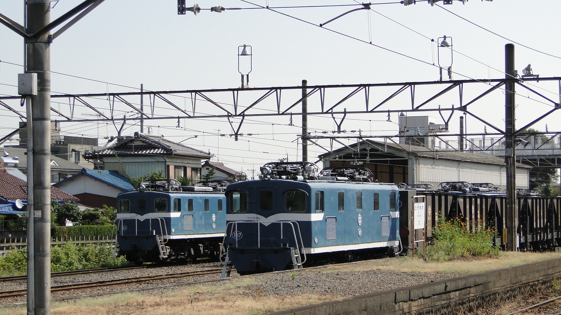
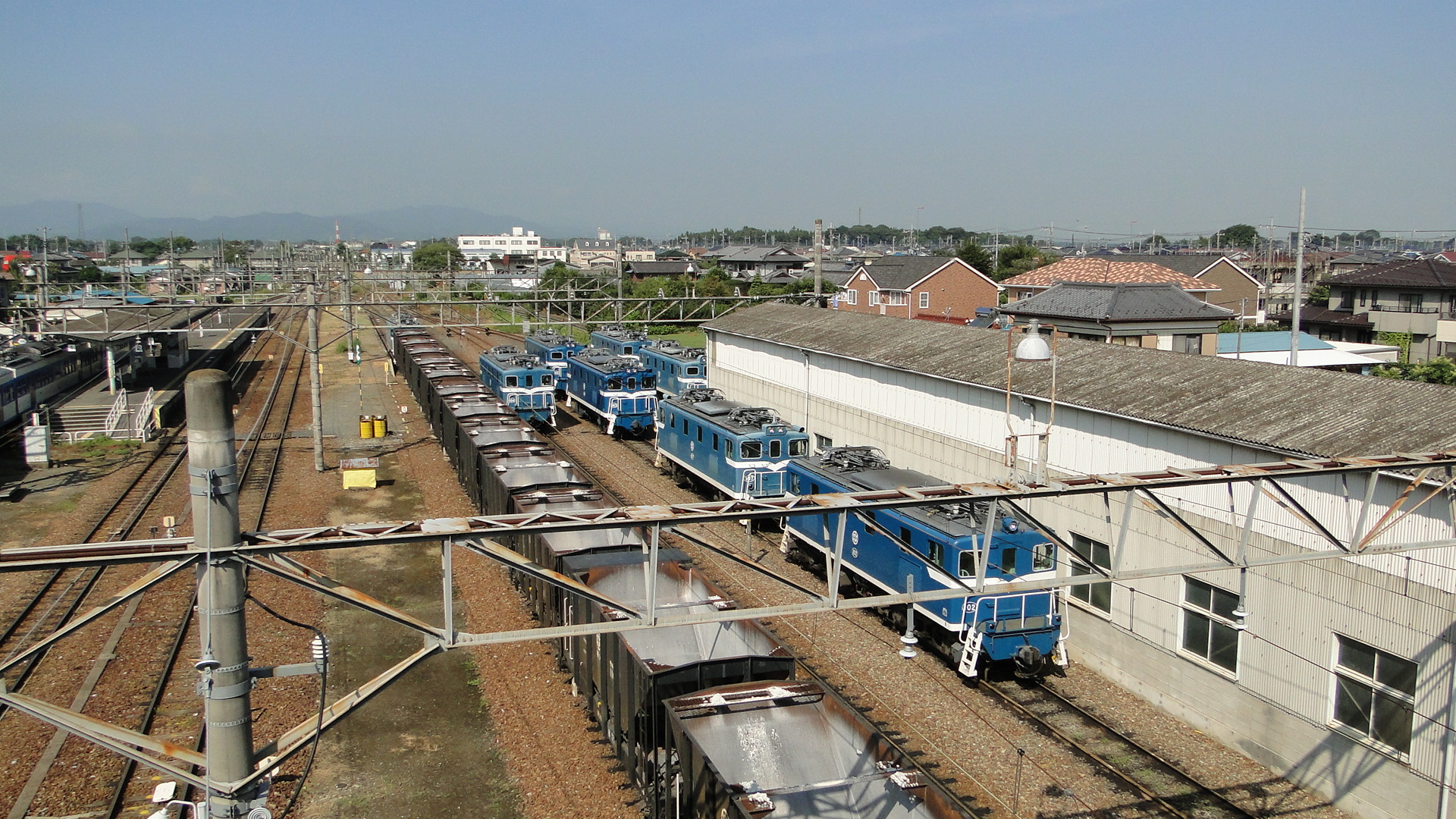
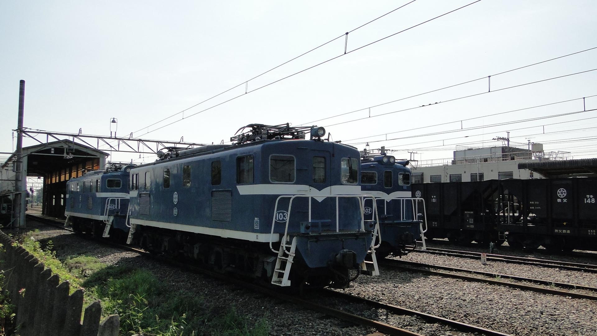
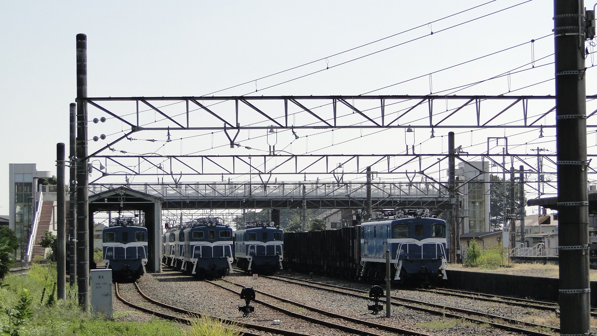
I walked a lap around the yard and the station and checked out the surroundings. Takekawa is a very quiet little suburb, but the locals seem to be used to railfans hanging around. I greeted one or two people who didn't seem too upset with me loitering and taking photos of the infrastructure. I was also greeted by around 30-odd small children on a school excursion crossing the pedestrian bridge.
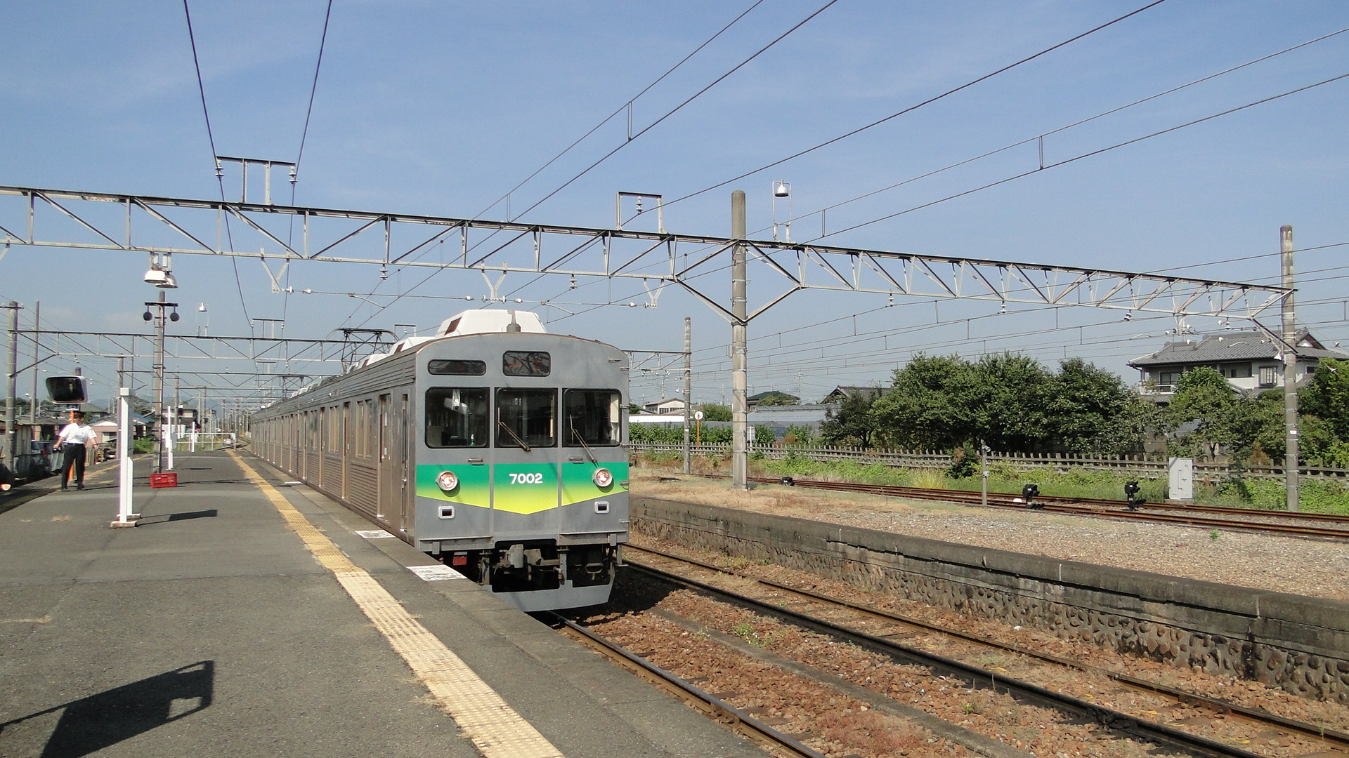
After walking about 3/4 of my lap the 'express' EMU passed and I got a shot of it from the level crossing east of the station.
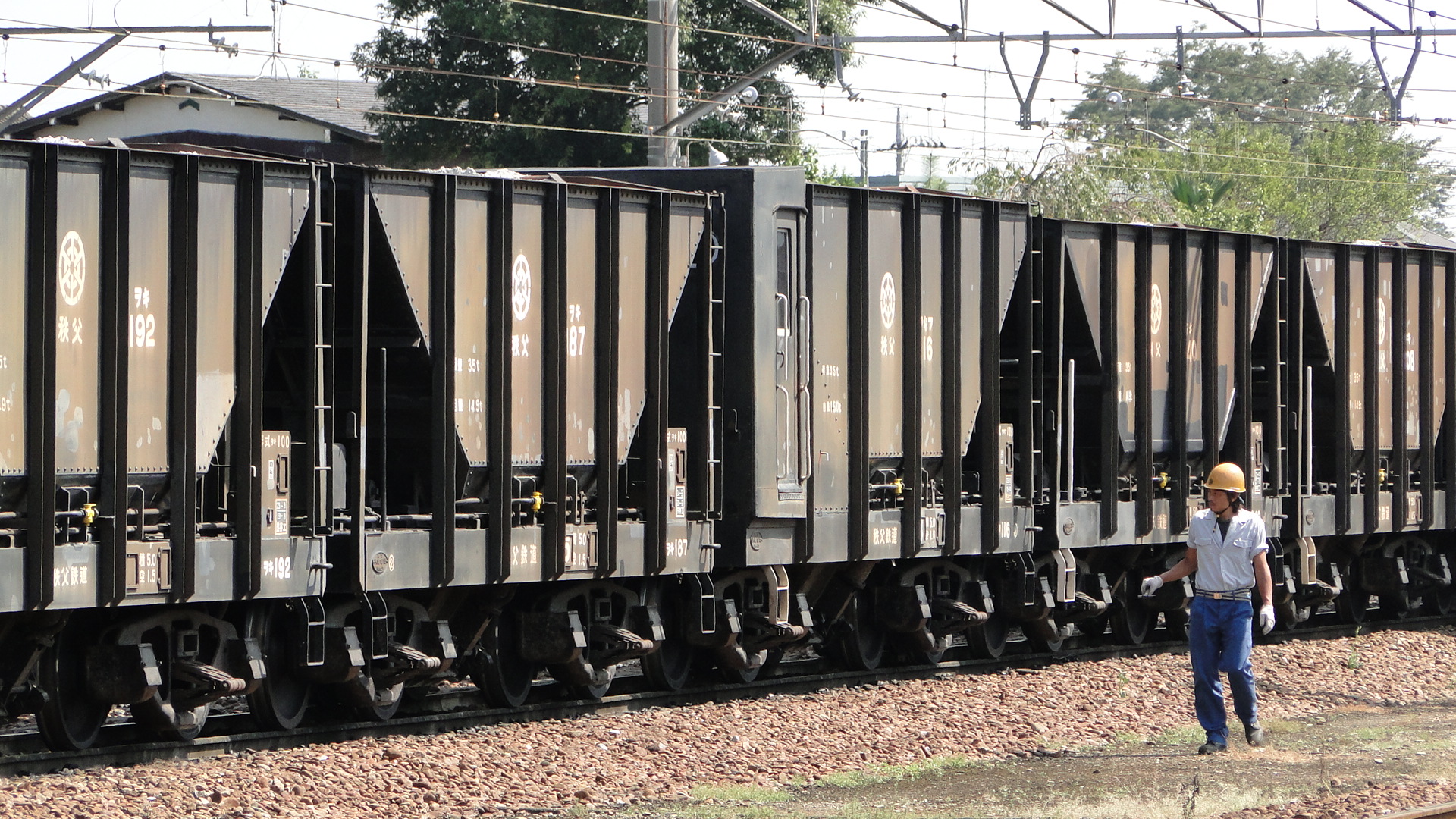
I looked again at my timetable and realised that there was to be another freight coming in and so positioned myself on the station island platform. I watched as one of the staff inspected (and tightened) the handbrakes on a rake of limestone hoppers (WAKIs).
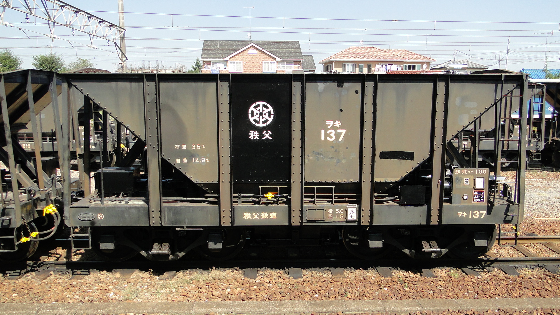
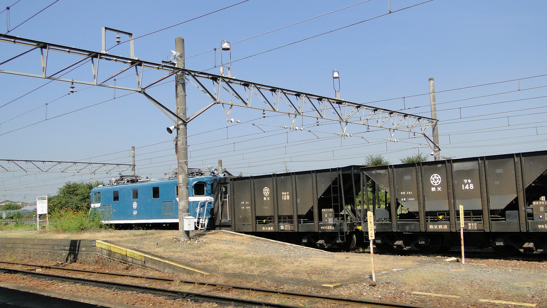
The level crossing west of the station then sounded. The previous east-bound passenger train had already passed and so I realised I was finally going to see a freight movement.
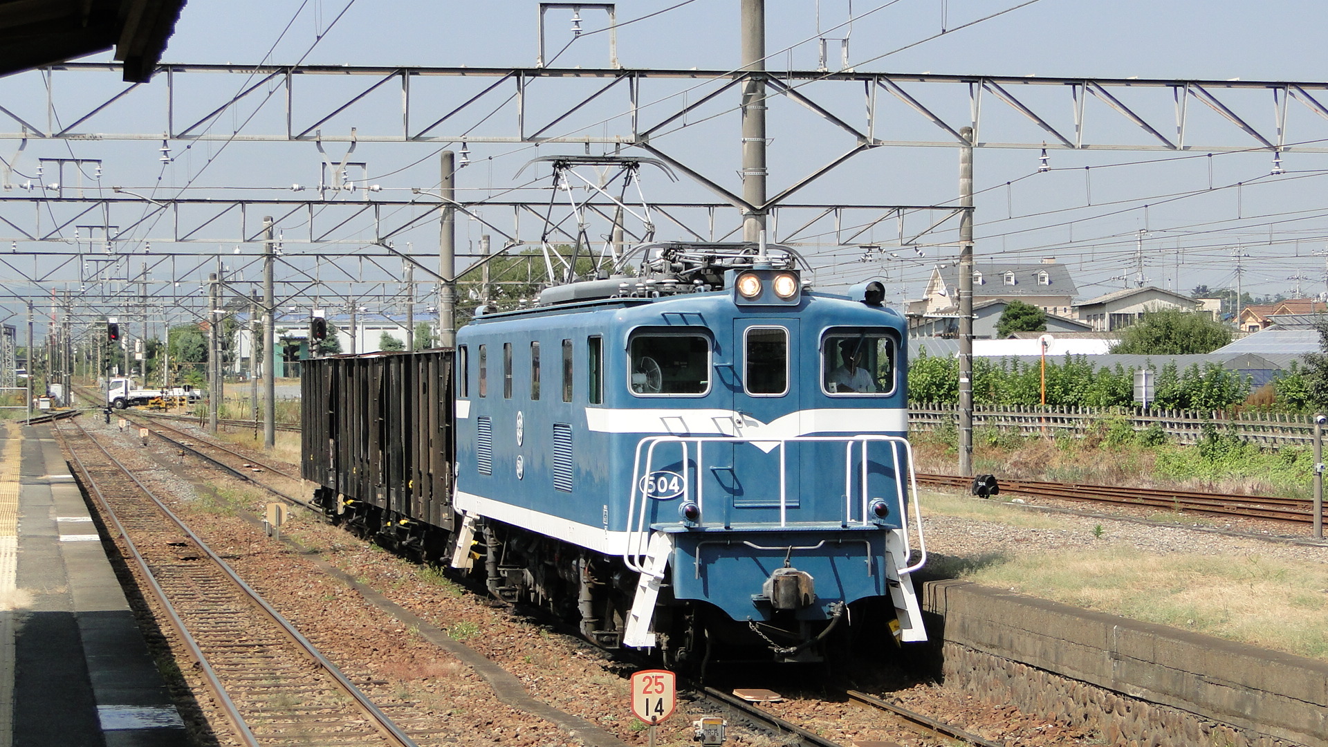
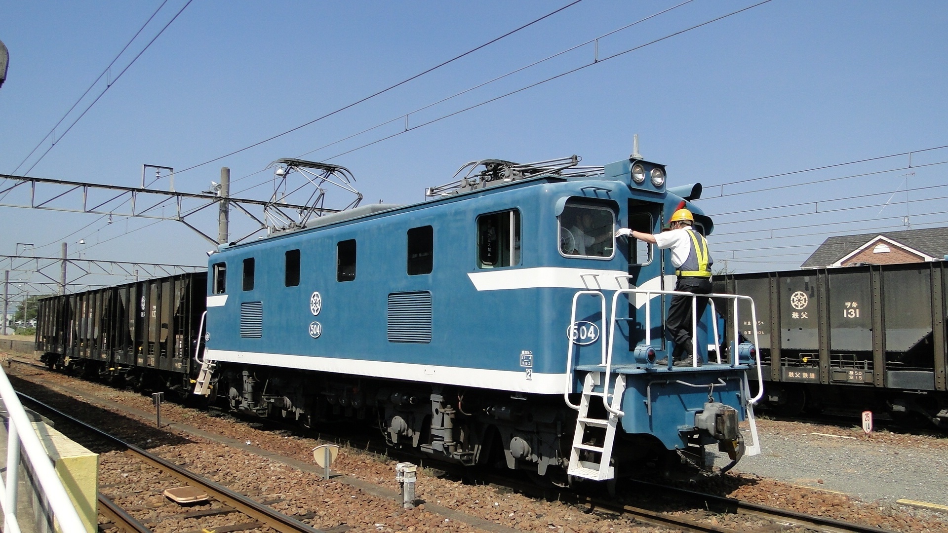
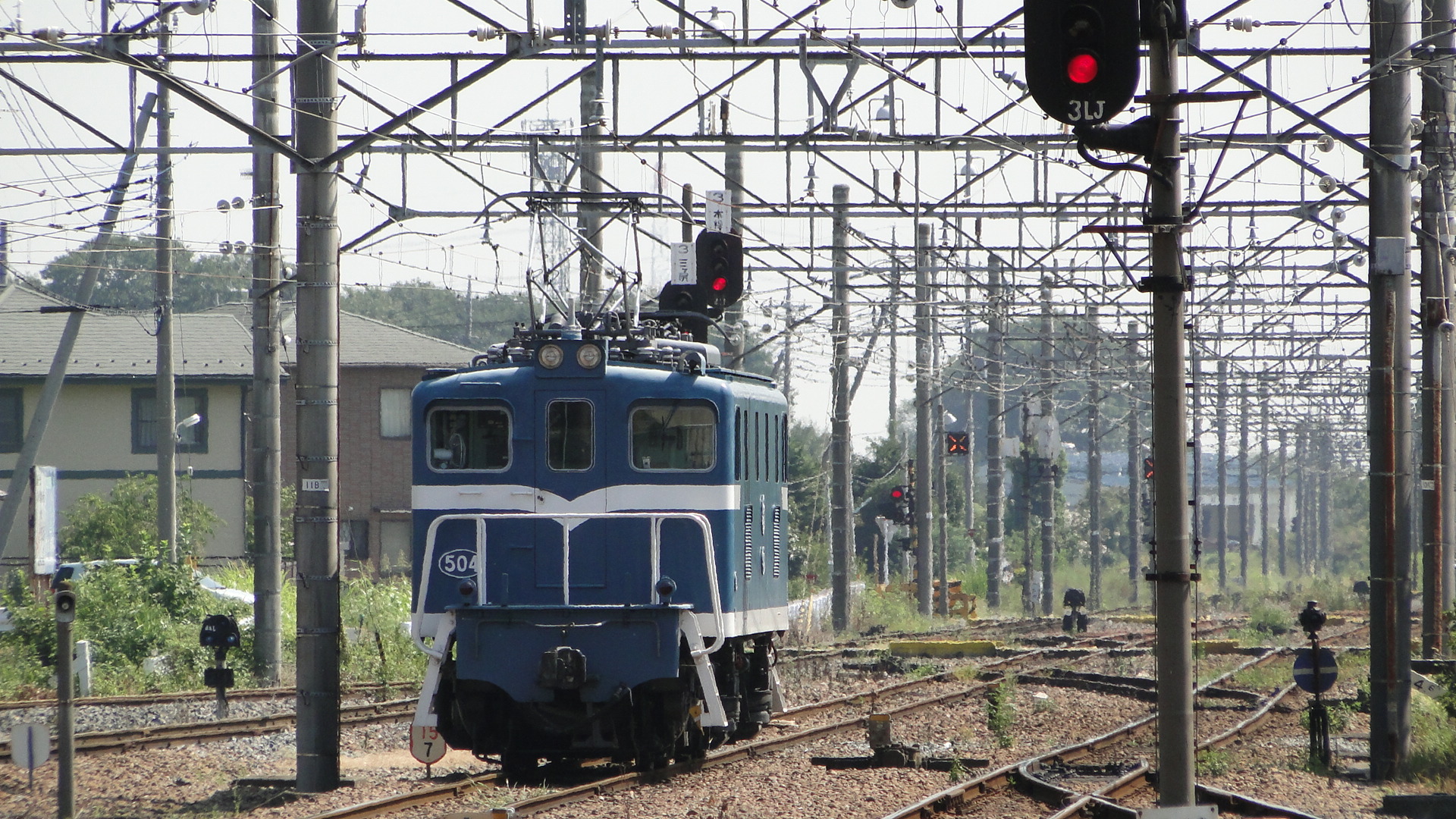
In came locomotive 504 with a small rake of limestone hoppers. It stopped on the road closest to the platform and another engineer jumped on the front. They then left the hoppers and trundled down the rails towards the factory.
That then ended my brief tour of the Chichibu. I returned to Kumagaya on the next passenger service and took the Shinkansen into Tokyo. The rest of the afternoon was then spent with friends in Akihabara.
As per usual, with any freight railway in any country, any timetables available must be taken with a level of doubt. The paths set for trains are only really useful when there is a train to be moved. I had a feeling that there were too many stored locos in the yard and this turned out to be true; as out of the 5 movements to be seen in the timeframe I was there, only one ran.
Either way, I was more than content with seeing preserved locomotives still operating and was also impressed with the other hand-me-down rolling stock on the Chichibu.
Oh! That's right, I was also there to see the Paleo Express, which was meant to run on that day.
...It didn't...
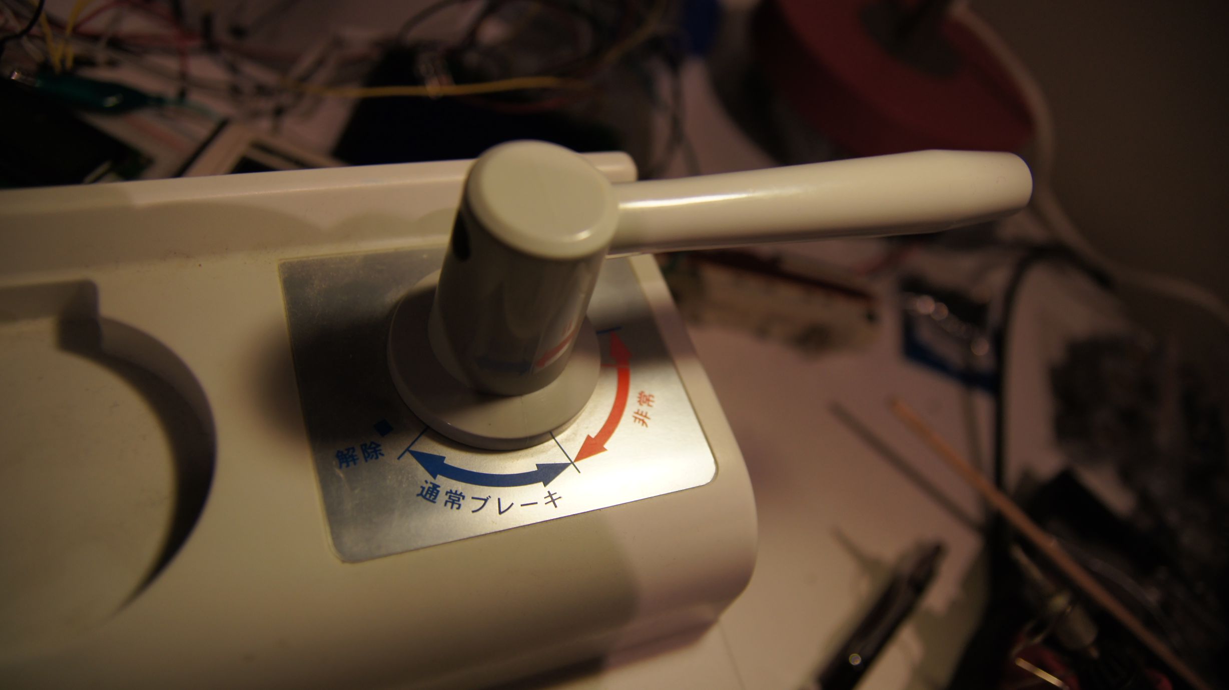
An attempt to simulate Acceleration and Braking
In my previous post, I'd managed to get my Densha-De-Go Dreamcast controller hooked up to my Arduino Mega. Now although this now meant that I had a great way to control my model railroad, it also meant I had to work out how to code a throttle and a brake lever.
The rules
After a few hours of plotting, I had decided on the following system. It involves a 6-position throttle and an 11-position brake. Each 'position' is to have a 'max speed' and 'speed adjust' associated with it.
Notes
- It is to be assumed that if the brake is on, the throttle is automatically disabled
- MAX is 255 on the PWM Throttle (or max voltage from supply)
- At Throttle 0, the train is neither powering nor braking; we will simply slowly decrement the speed
- There is no feedback to know how fast the train is currently travelling
- There are multiple emergency brake points on the throttle, but we don't care about them.
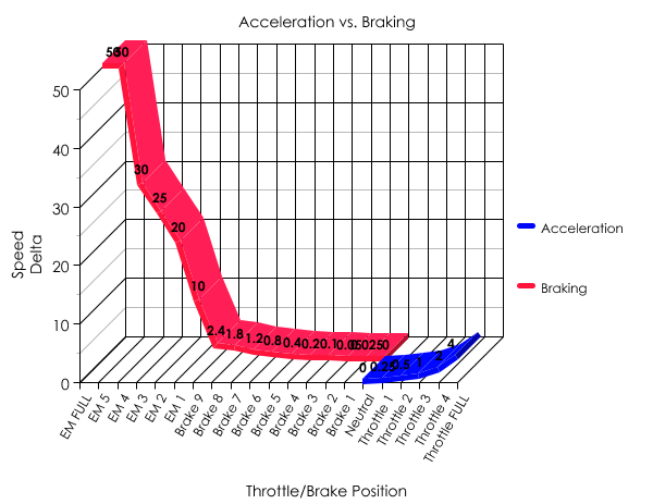
The next table shows my acceleration and braking deltas. This will be a simple addition and subtraction on the current speed.
| Lever position | Max Speed | Speed Adjustment |
|---|---|---|
| Emergency Full | Instant Stop | |
| Emergency 5 | -50 | |
| Emergency 4 | -30 | |
| Emergency 3 | -25 | |
| Emergency 2 | -20 | |
| Emergency 1 | -10 | |
| Brake 9 | -2.4 | |
| Brake 8 | -1.8 | |
| Brake 7 | -1.2 | |
| Brake 6 | -0.8 | |
| Brake 5 | -0.4 | |
| Brake 4 | -0.2 | |
| Brake 3 | -0.1 | |
| Brake 2 | -0.05 | |
| Brake 1 | -0.025 | |
| Throttle 0 | 0 | 0.00 |
| Throttle 1 | 55 | +0.25 |
| Throttle 2 | 75 | +0.5 |
| Throttle 3 | 90 | +1 |
| Throttle 4 | 100 | +1.75 |
| Throttle 5 | 120 | +2.5 |
And now a better way to represent it.
The code
The table above translates to code quite easily... the goal is to have the lever position values coded into an array and then just select the correct entry. Once determined, the main code loop can then determine how to adjust the current voltage output to the rails.
const int throttle_positions = 21;
const int throttle_absolute_maximum_speed = 255;
const int throttle_minimum_speed = 20;
int current_throttle_position = -1; // 0 is EM FULL. Lever must be moved to EM FULL to begin.
float current_speed = 0;
float target_speed = 0;
int throttle_max_speed[throttle_positions] =  {
	0,0,0,0,0,0,0,0,0,0,0,0,0,0,0, //brake positions and Throttle 0
	0, 55, 75, 90, 100, 120
};
float throttle_delta[throttle_positions] = 	{
	0.025, 0.05, 0.1, 0.2, 0.4, 0.8, 1.2, 1.8, 2.4, 10, 20, 25, 30, 50, 9999, //brake
	0.00 /*coast*/, 0.25, 0.5, 1, 1.75, 2.5
};
We then need to determine the current throttle position. We will make it that, at the start of code execution, the train should not move until the throttle has been reset to EM Full and the throttle at '0'.
#define BRAKE_MASK 0xf0
#define BRAKE_SHIFT 4
#define ACCEL_MASK 0x07
void read_throttle_position() {
	int accel = packet.data[6] & ACCEL_MASK;
	int brake = (int)((packet.data[7] & BRAKE_MASK) >> BRAKE_SHIFT);

	if (current_throttle_position == -1) {
		//check that we have EM FULL and Neutral
		if (brake  == 15 && accel  == 1) {
			//set the initial '0' (EM FULL) position.
			current_throttle_position = 0;
			lcd.clear();
		}
	} else {
		if (brake != 1) { //1 == "BRAKE 1", if it's higher, we're braking.
			if (brake > 0) current_throttle_position = brake;
		} else { //BRAKE == 1 and then we check the throttle
			//we're accelerating.
			if ((accel + 15) < 22) current_throttle_position = accel + 15;
		}
	}
}
And now the main game loop needs to determine the current lever locations and then choose the appropriate action:
void update_speed() {
		digitalWrite(13, LOW);
	//make sure we are allowed to go.
	if (current_throttle_position >= 0) {
		if (current_speed > throttle_max_speed[current_throttle_position - 1]) {
			current_speed -= throttle_delta[current_throttle_position - 1];

			//braking... don't go negative.
			if (current_speed < throttle_minimum_speed)
				current_speed = 0;

		} else if (current_speed < throttle_max_speed[current_throttle_position - 1]) {

			//accelerating, so start from minimum speed.
			if (current_speed < throttle_minimum_speed)
				current_speed = throttle_minimum_speed;

			current_speed += throttle_delta[current_throttle_position - 1];

			//don't go faster than current throttle max setting.
			if (current_speed > throttle_max_speed[current_throttle_position - 1])
				current_speed = throttle_max_speed[current_throttle_position - 1];
		}

		//set light if we have met max speed for throttle.
		if (current_speed == throttle_max_speed[current_throttle_position - 1])
			digitalWrite(13, HIGH);

		//output speed to railway.
		analogWrite(7, current_speed);
	} else {
		//flash the LED to alert user to reset controls.
		delay(200); //delay a little to flash the LED
		digitalWrite(13, HIGH);
		delay(200);
	}
}
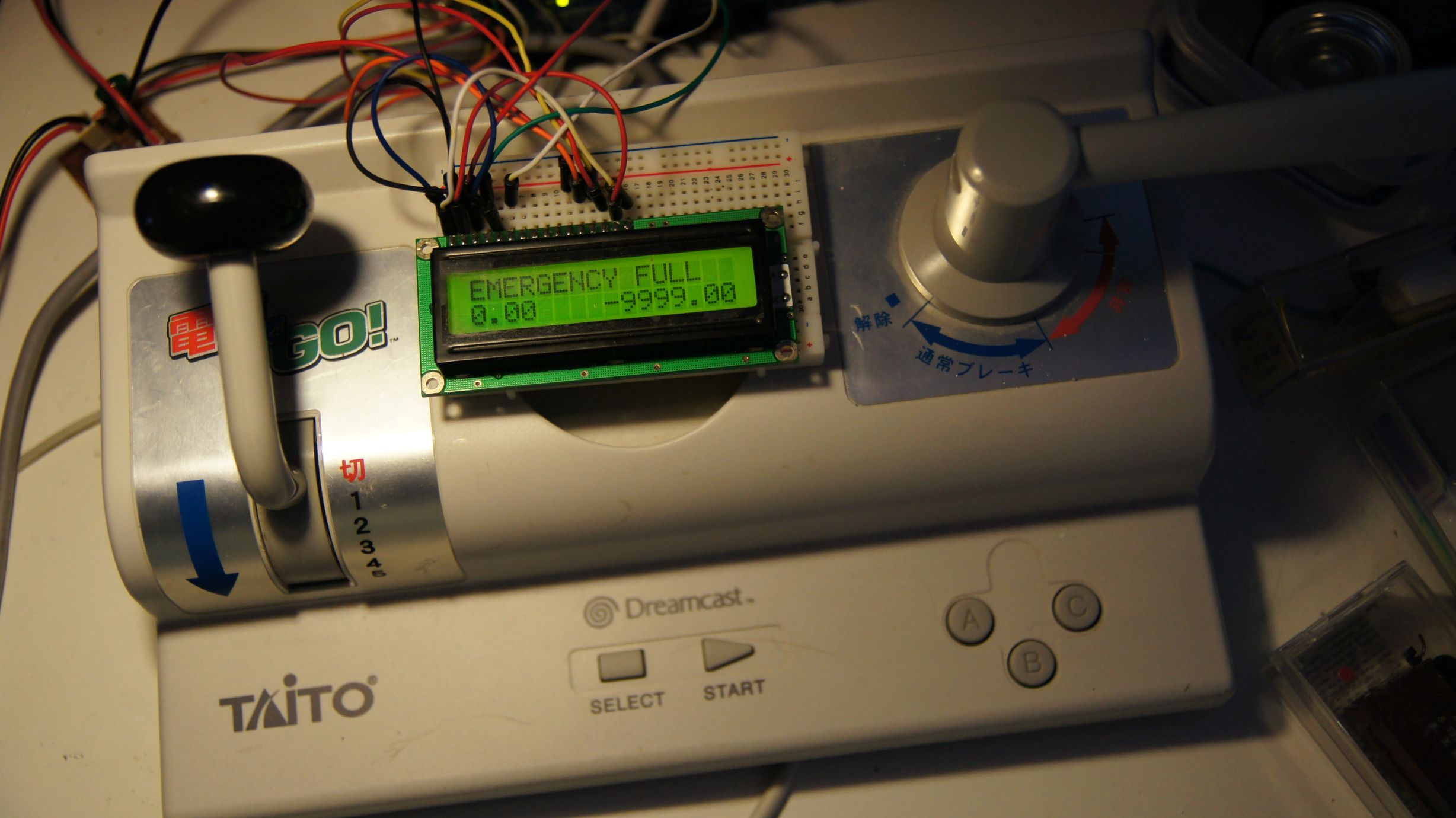
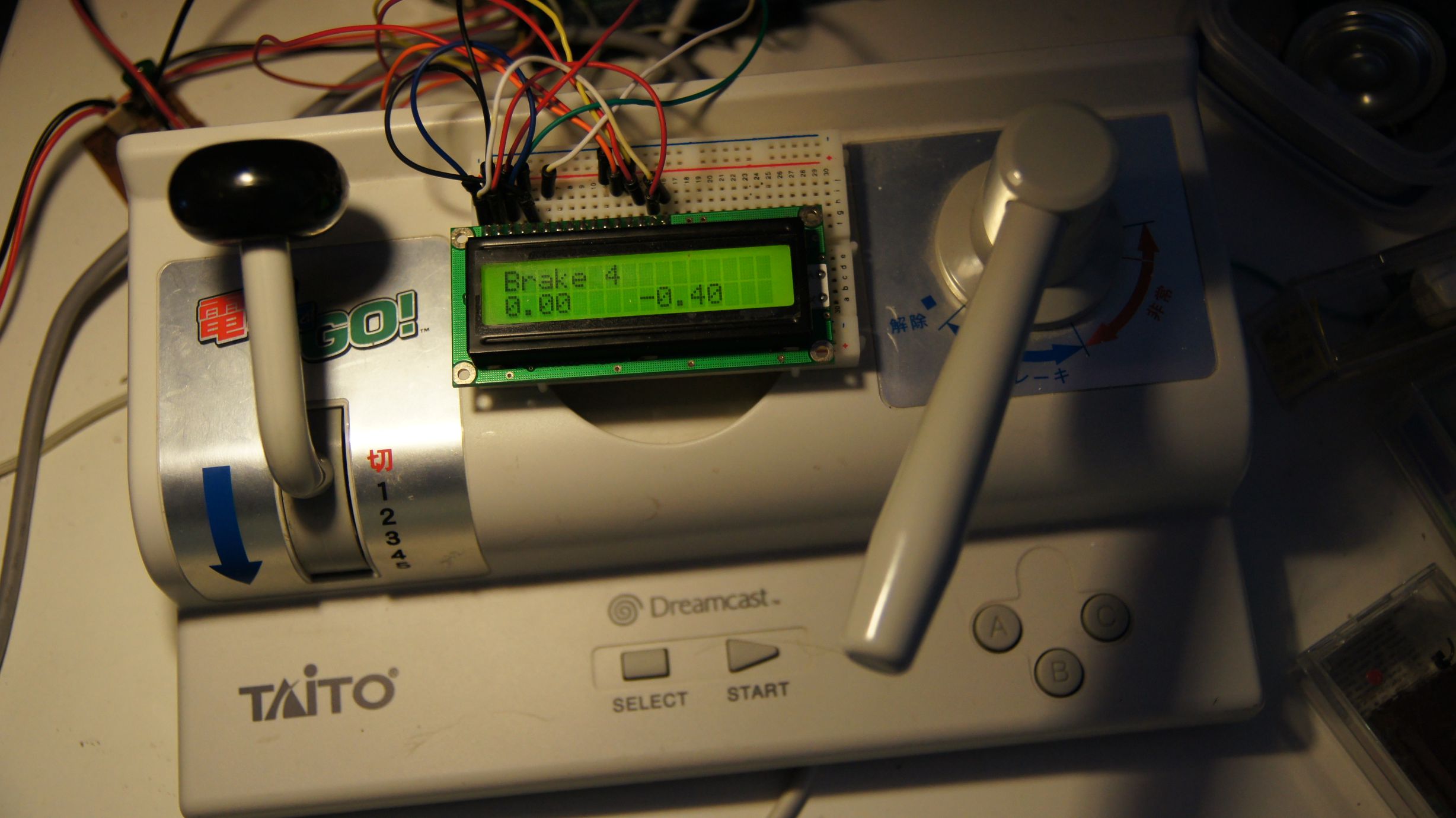
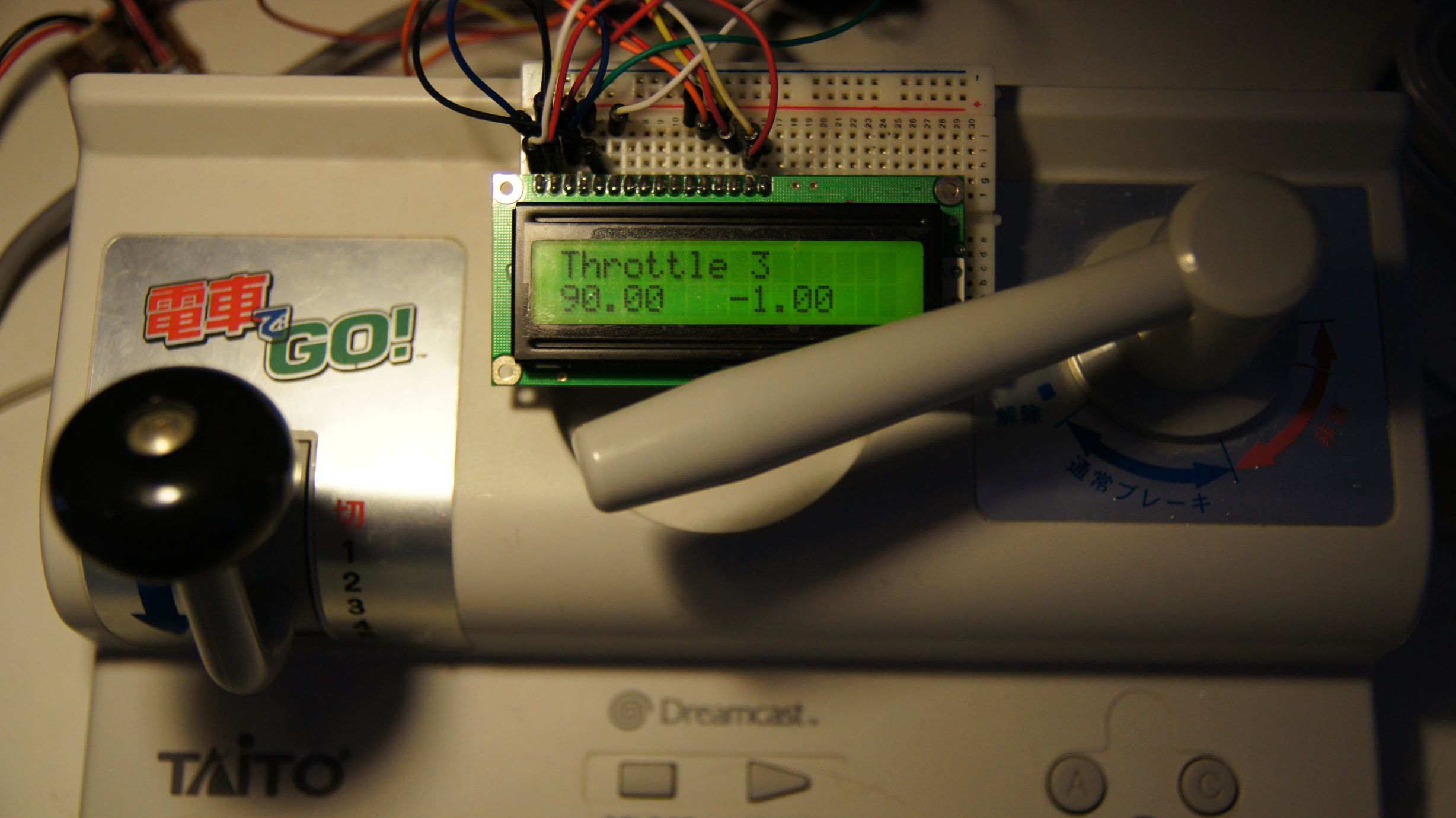
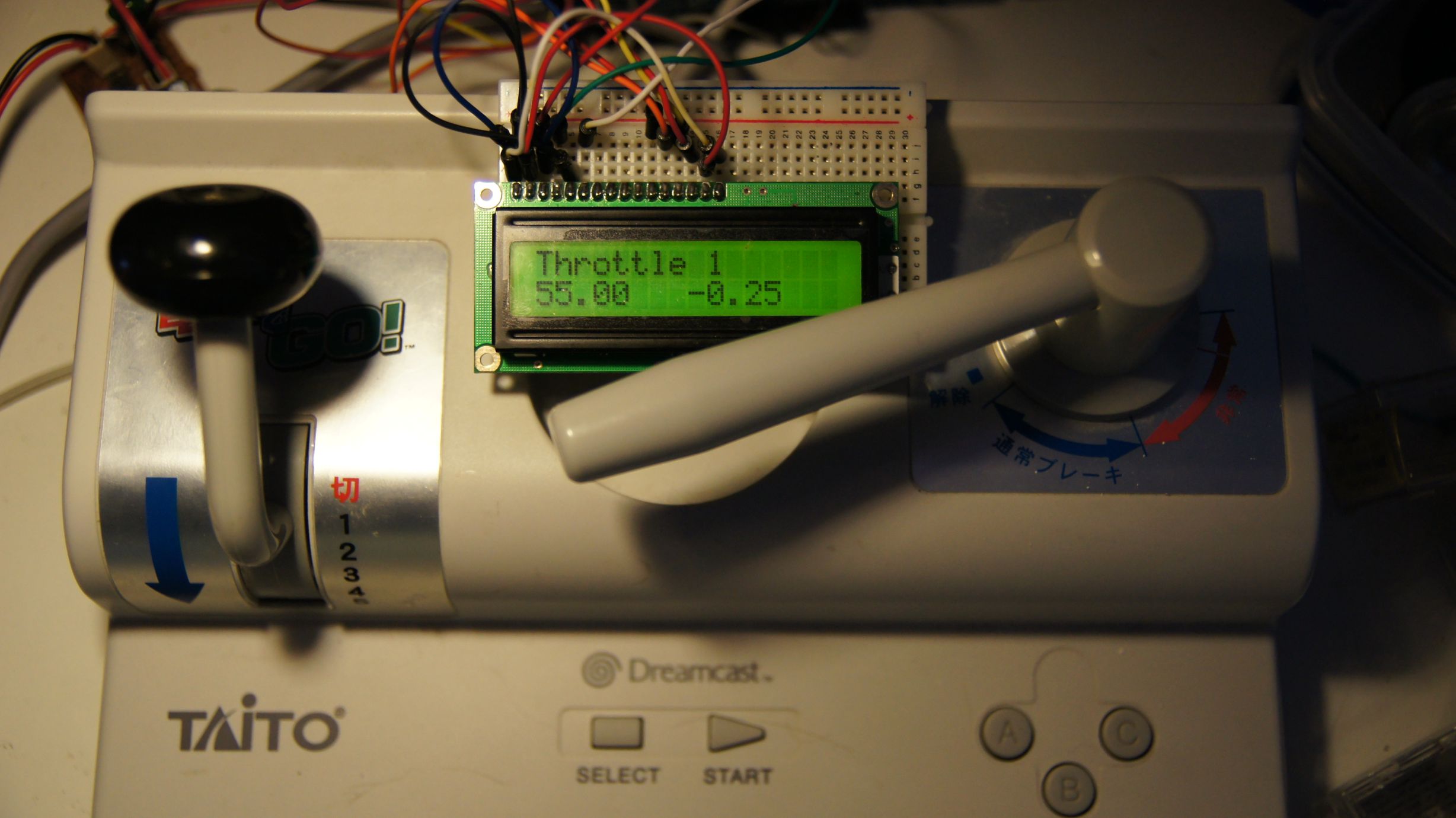
There's also some code in the main loop to update the 16x2 LCD I've hooked up. Since we need to reset the controller when we start, it'll tell you to do so and afterwards will tell you the current throttle/brake position, current speed and speed delta.
 Download the source code here.
Note that this does not include the full arduino-maple code. Download that here. You will also need the LiquidCrystal library from the Arduino site.
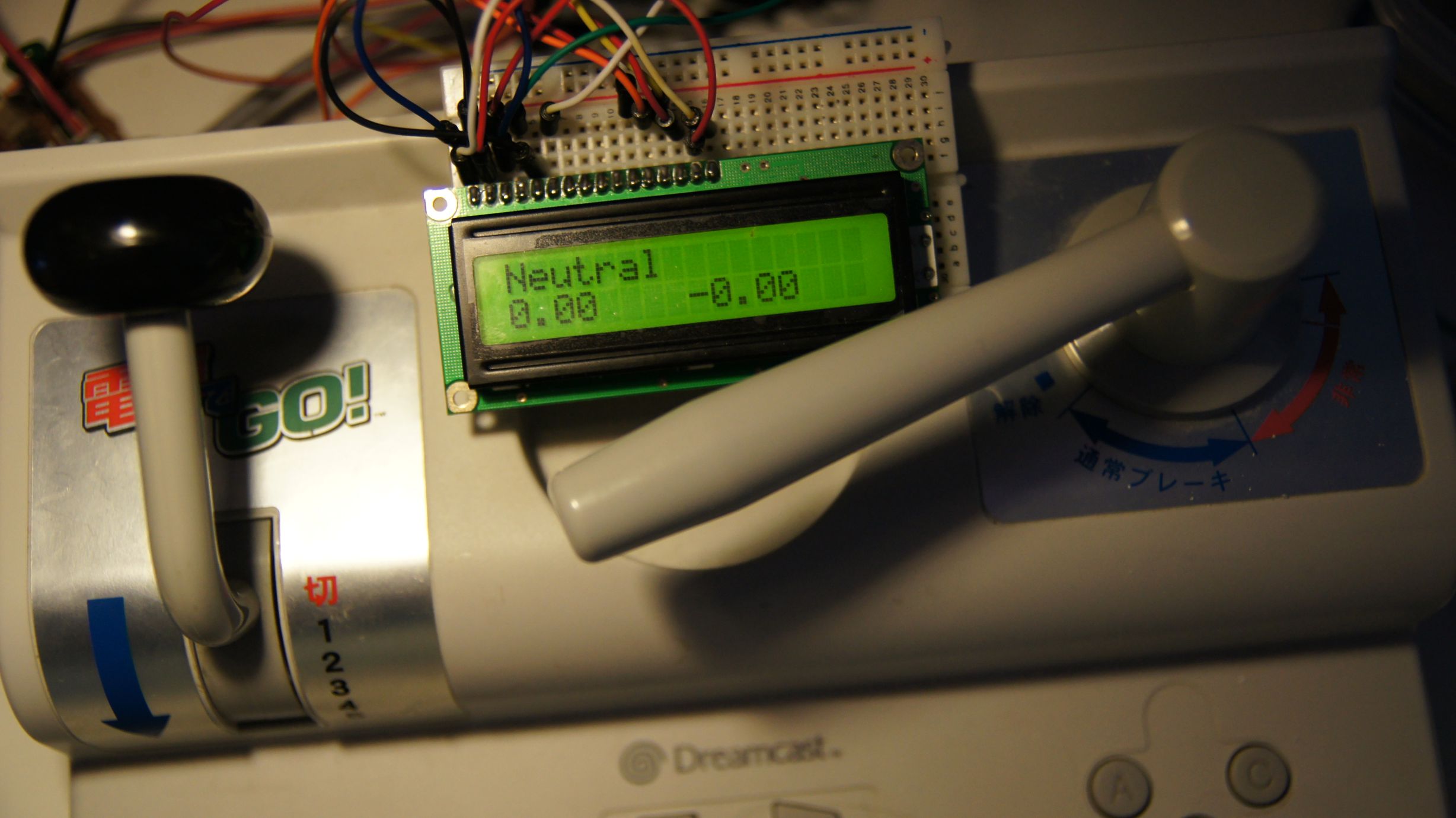
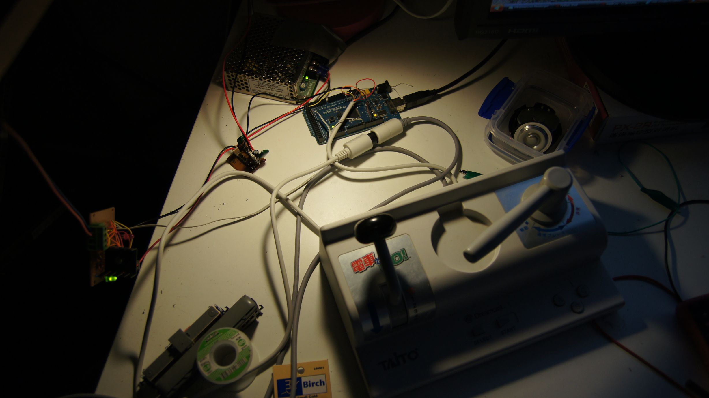
Action shots
Shown is the controller in certain positions. Note that the 'Throttle' positions may show a negative speed delta; this just means that they are no longer accelerating.
Arduino + Dreamcast Densha-De-Go Controller
I've had Densha-De-Go and the controller for the Dreamcast for a while now... I'd even invested a few hours in playing the actual game, but the accuracy required is crazy. Supposedly in Japan it's that realistic that even real train drivers have a hard time getting it spot on :)
Anyway, I'd wanted to get this going for train control for a while after managing to make a Wii Nunchuck control my trains.
You can find more information on the controller at SEGA Retro, SEGAGAGA Domain, Wikipedia, Play Asia and genki Video Games.
Previous attempts
Quite a few months ago I spent a few hours with my Densha-De-Go controller and my Arduino Mega in an attempt to get them to communicate. The goal was to be able to read the controller and then use it to control my model railroad. Unfortunately, I was doing this blind, running off information from Marcus Comstedt's 'Dreamcast Programming' site; specifically his breakdown of the Maple Bus Protocol.
I ended up with nothing working and sent out a few pleas for help on the Arduino forum and to Marcus himself. I received information regarding the fact that it should work (the Arduino had the horsepower), but I would have to ensure the timing was intricate and that the Arduino was always ready to receive data.
I then posted to the Arduino Forum for help. A few months later WzDD came to my rescue with word that he had successfully made the Arduino communicate with a Dreamcast Controller. I hadn't had much time up until now to work on this, and WzDD hadn't done any further work on it, so I took it that he just wanted to prove the concept and that I'd have to get off my backside to make things progress further. In the end, I did want to get my controller functioning.
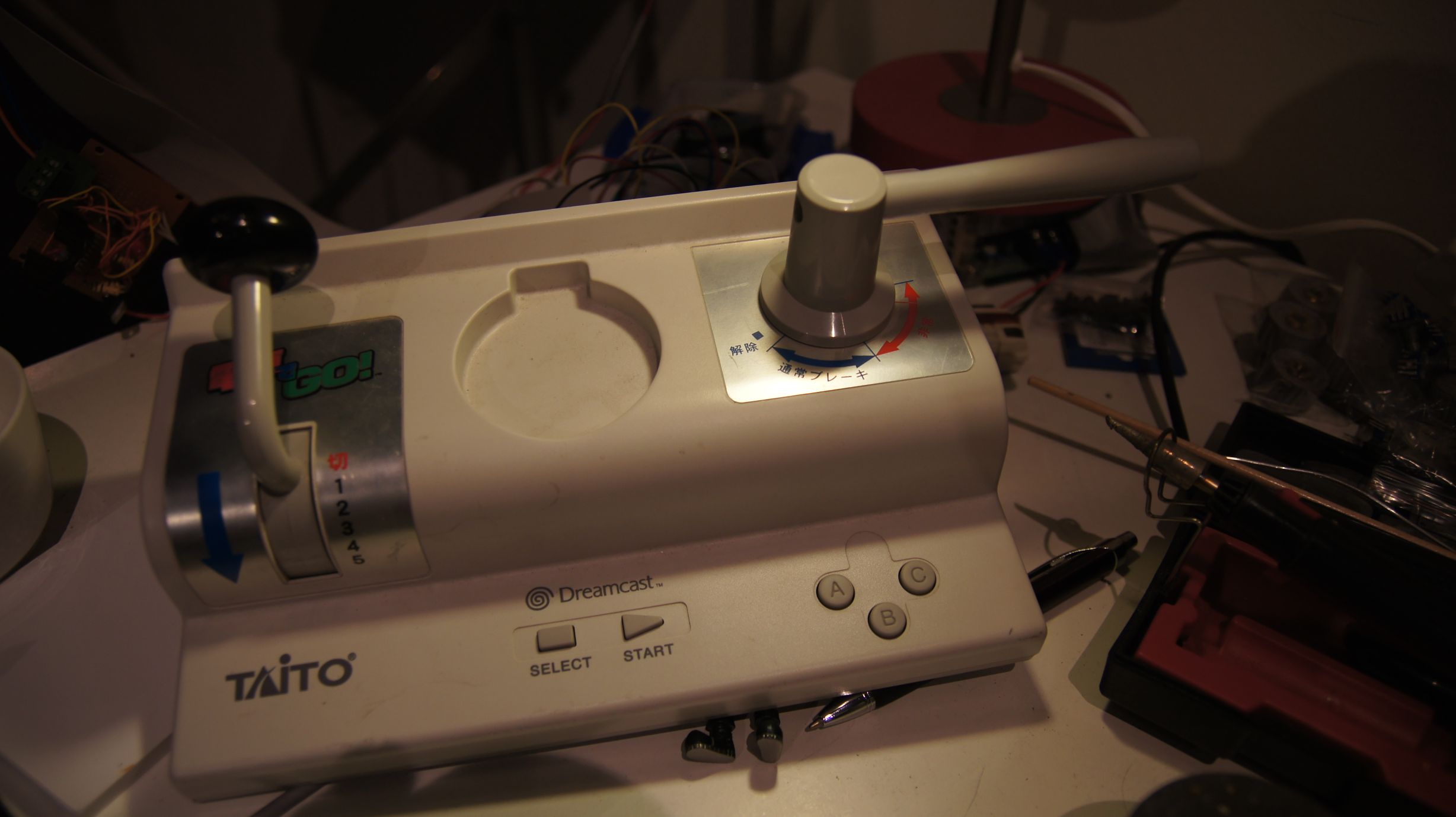
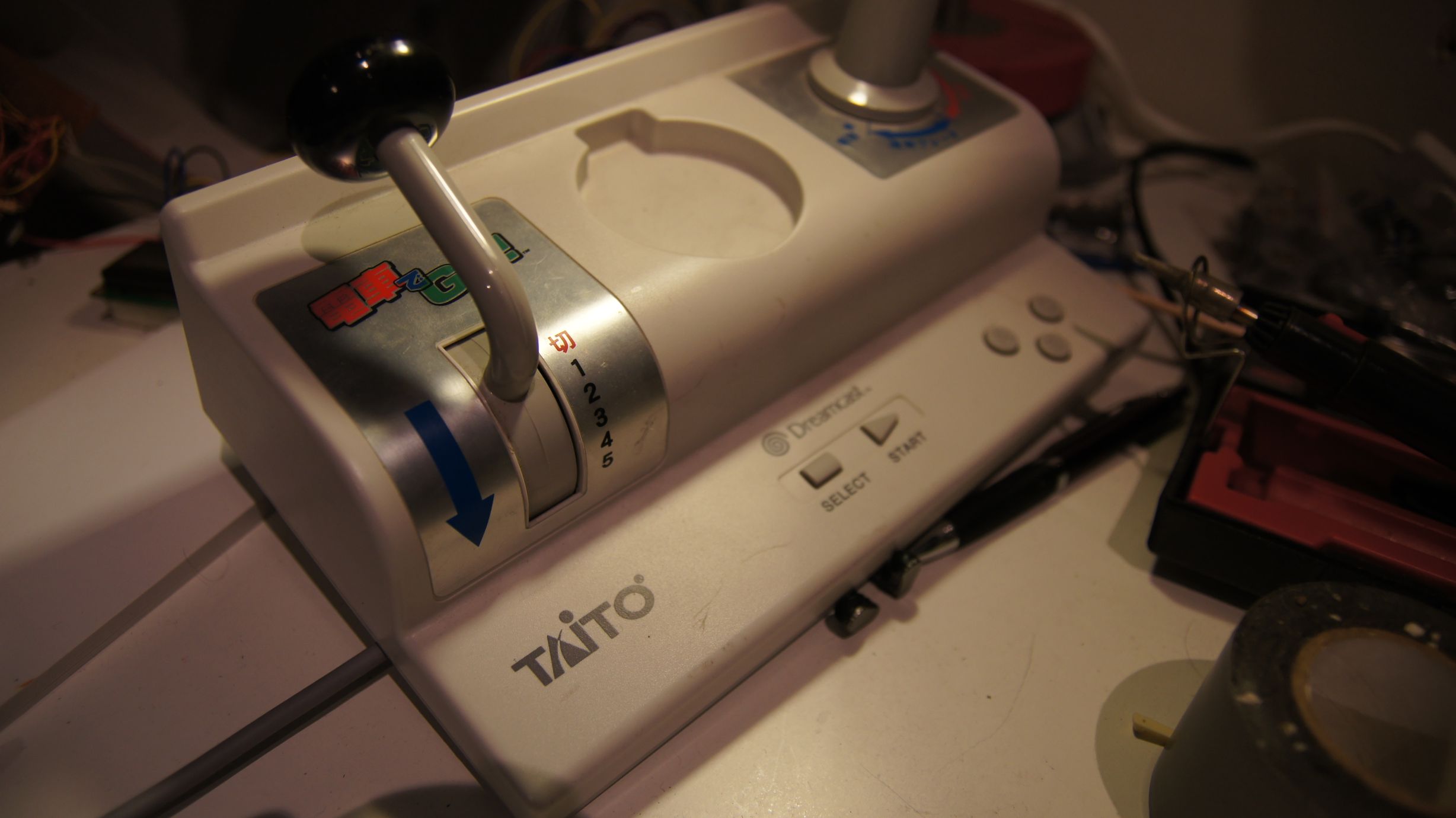
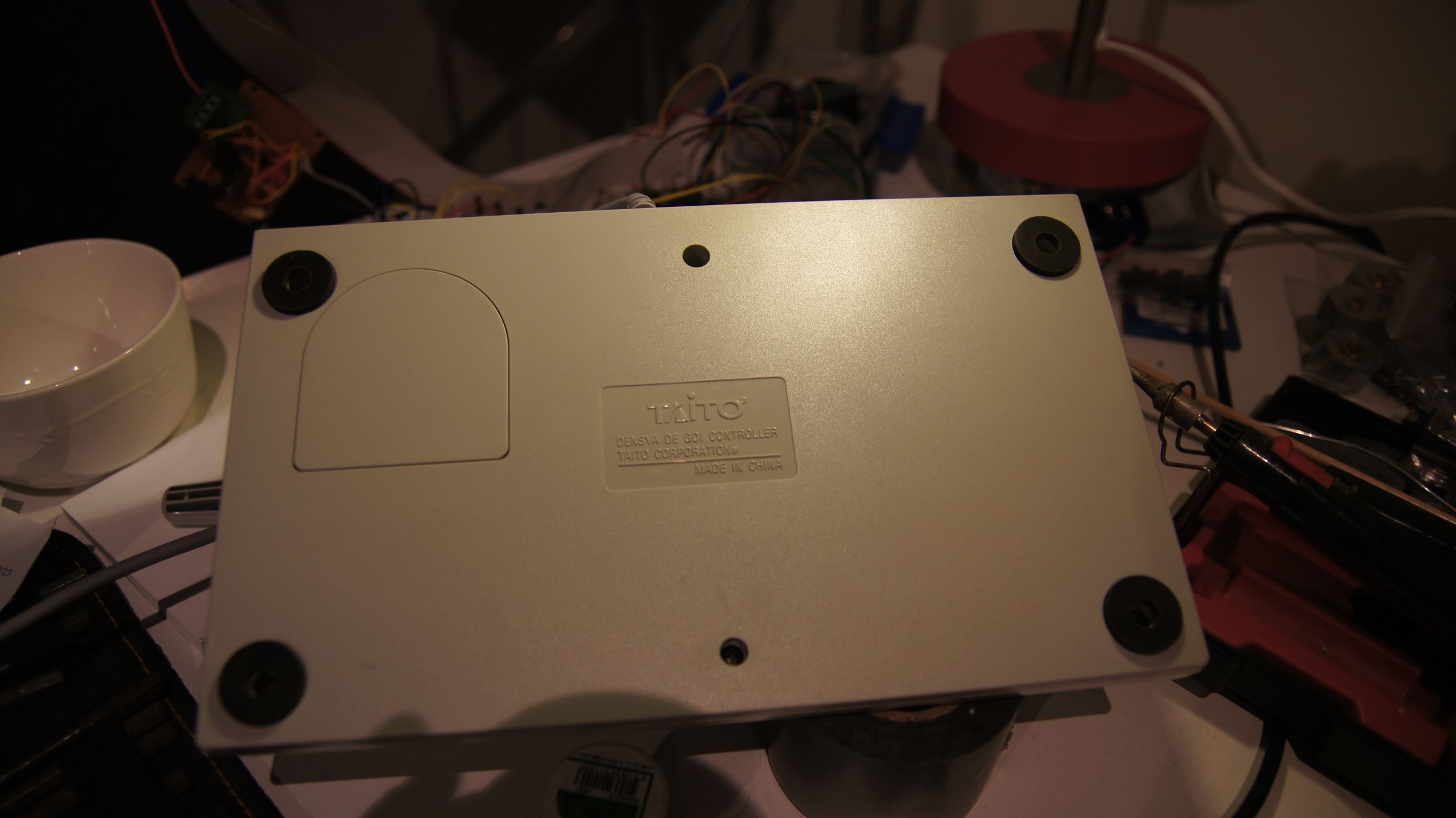
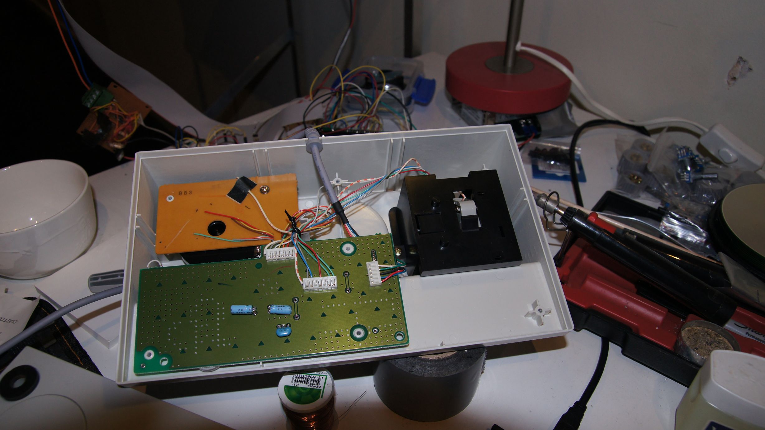
I had previously had everything I needed to test this again, so I gave it another go. My previous setup was a cut-in-half Dreamcast controller extension cable and my Densha-De-Go controller. The extension cable meant I didn't have to hack around with the actual controller or port imitation.
Getting set up...
Due to the requirement to use assembler for the actual low-level controller interactions, we cannot use the Arduino IDE and must use WinAVR (or just avrdude on Linux.) Download this from here (select the latest version) and install to the default directory.
You then need to download the arduino-maple source code and extract somewhere locally. I've put the folder on C:\arduino-maple\.
Open Programmers Notepad [WinAVR] from the start menu and then open the arduino-maple.cpp file from where it has been extracted. (C:\arduino-maple\arduino-maple.cpp in my case.)
If all is installed correctly, then you should be able to choose Tools - [WinAVR] Make All and have the following output in the output window:
> "make.exe" all
avr-gcc -Wall -g2 -gstabs -Os -fpack-struct -fshort-enums -ffunction-sections -fdata-sections -ffreestanding -funsigned-char -funsigned-bitfields -mmcu=atmega328p -DF_CPU=16000000UL -I./arduino -c arduino/pins_arduino.c -o build/arduino/pins_arduino.o
In file included from arduino/wiring_private.h:30,
                 from arduino/pins_arduino.c:26:
c:/winavr-20100110/lib/gcc/../../avr/include/avr/delay.h:36:2: warning: #warning "This file has been moved to <util/delay.h>."
...
Lots of warnings, no errors...
...
avr-g++ -Os -Wl,-gc-sections -mmcu=atmega328p  build/arduino/pins_arduino.o build/arduino/WInterrupts.o build/arduino/wiring.o build/arduino/wiring_analog.o build/arduino/wiring_digital.o build/arduino/wiring_pulse.o build/arduino/wiring_shift.o build/./arduino-maple.o build/arduino/HardwareSerial.o build/arduino/Print.o build/arduino/Tone.o build/arduino/WMath.o build/arduino/WString.o build/./libmaple.o -o app.elf
avr-objcopy -R .eeprom -O ihex app.elf  app.hex
avr-size --format=avr --mcu=atmega328p app.elf
AVR Memory Usage
----------------
Device: atmega328p

Program:    3380 bytes (10.3% Full)
(.text + .data + .bootloader)

Data:        796 bytes (38.9% Full)
(.data + .bss + .noinit)

> Process Exit Code: 0
> Time Taken: 00:02
Now, as you can see above... that's not my Arduino! I have an Arduino Mega and therefore we need to adjust the Makefile correctly for my setup. Here you'll need to know the CPU code, interface type and the port number. Also make sure you change the upload task to program so that we can use the menu items in WinAVR.
# Makefile for building small AVR executables, supports C and C++ code
# Author: Kiril Zyapkov
# Hacked up by nfd

SOURCE_DIRS = . arduino
INCLUDE_DIRS = arduino
MMCU = atmega1280
F_CPU = 16000000UL
SRC_ROOT = .
BUILD_DIR = build

CFLAGS = -Wall -g2 -gstabs -Os -fpack-struct -fshort-enums -ffunction-sections \
 -fdata-sections -ffreestanding -funsigned-char -funsigned-bitfields \
 -mmcu=$(MMCU) -DF_CPU=$(F_CPU) $(INCLUDE_DIRS:%=-I$(SRC_ROOT)/%)

CXXFLAGS = -Wall -g2 -gstabs -Os -fpack-struct -fshort-enums -ffunction-sections \
 -fdata-sections -ffreestanding -funsigned-char -funsigned-bitfields \
 -fno-exceptions -mmcu=$(MMCU) -DF_CPU=$(F_CPU) $(INCLUDE_DIRS:%=-I$(SRC_ROOT)/%)

LDFLAGS = -Os -Wl,-gc-sections -mmcu=$(MMCU) #-Wl,--relax

TARGET = $(notdir $(realpath $(SRC_ROOT)))
CC = avr-gcc
CXX = avr-g++
OBJCOPY = avr-objcopy
OBJDUMP = avr-objdump
AR  = avr-ar
SIZE = avr-size

SRC = $(wildcard $(SOURCE_DIRS:%=$(SRC_ROOT)/%/*.c))

CXXSRC = $(wildcard $(SOURCE_DIRS:%=$(SRC_ROOT)/%/*.cpp))

ASMSRC = $(wildcard $(SOURCE_DIRS:%=$(SRC_ROOT)/%/*.S))

OBJ = $(SRC:$(SRC_ROOT)/%.c=$(BUILD_DIR)/%.o) $(CXXSRC:$(SRC_ROOT)/%.cpp=$(BUILD_DIR)/%.o) $(ASMSRC:$(SRC_ROOT)/%.S=$(BUILD_DIR)/%.o)

DEPS = $(OBJ:%.o=%.d)

$(BUILD_DIR)/%.o: $(SRC_ROOT)/%.c
	$(CC) $(CFLAGS) -c $< -o $@

$(BUILD_DIR)/%.o: $(SRC_ROOT)/%.S
	$(CC) $(CFLAGS) -c $< -o $@

$(BUILD_DIR)/%.o: $(SRC_ROOT)/%.cpp
	$(CXX) $(CXXFLAGS) -c $< -o $@

all: app.hex printsize

#$(TARGET).a: $(OBJ)
#	$(AR) rcs $(TARGET).a $?

app.elf: $(OBJ)
	$(CXX) $(LDFLAGS) $(OBJ) -o $@

$(BUILD_DIR)/%.d: $(SRC_ROOT)/%.c
	mkdir -p $(dir $@)
	$(CC) $(CFLAGS) -MM -MF $@ $<

$(BUILD_DIR)/%.d: $(SRC_ROOT)/%.cpp
	mkdir -p $(dir $@)
	$(CXX) $(CXXFLAGS) -MM -MF $@ $<

#$(TARGET).elf: $(TARGET).a
#	$(CXX) $(LDFLAGS) $< -o $@

app.hex: app.elf
	$(OBJCOPY) -R .eeprom -O ihex $<  $@


clean:
	echo $(RM) $(DEPS) $(OBJ) $(TARGET).*

printsize:
	avr-size --format=avr --mcu=$(MMCU) app.elf

# Programming support using avrdude. Settings and variables.
PORT = /dev/tty.usbserial-A700ekGi
#PORT = /dev/ttyUSB0
AVRDUDE_PORT = com3
AVRDUDE_WRITE_FLASH = -U flash:w:app.hex
MCU = atmega1280
AVRDUDE_PROGRAMMER = stk500v1
#AVRDUDE_FLAGS = -V -F -C \app\arduino-0021\hardware\tools\avr\etc\avrdude.conf
AVRDUDE_FLAGS = -V -F \
-p $(MCU) -P $(AVRDUDE_PORT) -c $(AVRDUDE_PROGRAMMER) \
-b $(UPLOAD_RATE)
UPLOAD_RATE = 57600
#
# Program the device.
INSTALL_DIR = \app\arduino-0021
AVRDUDE = avrdude
program: app.hex
	#python pulsedtr.py $(PORT)
	$(AVRDUDE) $(AVRDUDE_FLAGS) $(AVRDUDE_WRITE_FLASH)
The first line in the program target (Line 93) 'pushes' the reset button on the Arduino. As we don't have Python installed we have to do this manually. So, build the source code via the [WinAVR] Make All and ensure there are no errors. Now press the 'reset' button on the Arduino and then quickly choose Tools - [WinAVR] Program. If all goes correctly then you'll see the code uploading to your Arduino:
#python pulsedtr.py /dev/tty.usbserial-A700ekGi
avrdude -V -F -p atmega1280 -P com3 -c stk500v1 -b 57600 -U flash:w:app.hex
avrdude: AVR device initialized and ready to accept instructions

Reading | ################################################## | 100% 0.05s

avrdude: Device signature = 0x1e9703
avrdude: NOTE: FLASH memory has been specified, an erase cycle will be performed
         To disable this feature, specify the -D option.
avrdude: erasing chip
avrdude: reading input file "app.hex"
avrdude: input file app.hex auto detected as Intel Hex
avrdude: writing flash (3508 bytes):

Writing | ################################################## | 100% 1.09s

avrdude: 3508 bytes of flash written
avrdude done.  Thank you.

> Process Exit Code: 0
> Time Taken: 00:03
And that's it, our the compiled code for the arduino-maple project is now on the Arduino and running!
Using the Python code on Windows
I lied, I said I didn't have Python installed... but I ended up installing it anyway. The job to convert the Python code to C# was going to take too long and, to prevent a debugging nightmare, I decided I would get the known-to-work Python code going under Windows first. So, I installed Python from the official website and then started learning :)
Note that I downloaded and installed Python Version 2.6.6 as this was the version that would have been available when arduino-maple was created.
After selecting 'IDLE' from the start menu, I was presented with a light-weight GUI. I opened up the 'maple.py' that's included with the arduino-maple code and attempted to compile it.
I had problems at the start, as in the included Makefile there are two declarations of CPU type. Initially I hadn't set these both correctly and the Arduino includes were not correctly compiled... make sure you carry out a proper clean whenever changing code; this includes manually deleting all of the .o files.
Once this was sorted, it all finally worked... sort of?
connecting to COM3:
connected
SENT: 0000200121
No device found at address:
0x20
SENT: 0000010100
1c20000501000000ff0f3f000000000000000000415400ff204f544920313030746e6f436c6c6f7
2202072652020202020200024191bdc94191958dd481e508815481c9bdc99591b98da5308195
cdb995bdc91881154c8c9b40481051d491551394d25494130b14d1480b911508080808007d00371 117
Command 5 sender 0 recipient 20 length 1c
Device information:
Functions  : CONTROLLER
Periph 1   : 0x3f0fff
Periph 2   : 0x0
Periph 3   : 0x0
Name       : ..TAITO 001 Controller      $.
License    : .....X...P.H..H..Y...S....\....[..T.....Q.I.I%M9M.0A.......P
Power      : 53251
Power max  : 32775
Play with the controller. Hit ctrl-c when done.
SENT: 010020090100000029
SENT: 010020090100000029
1111101010011111
SENT: 010020090100000029
1111101010011111
SENT: 010020090100000029
1111101010011111
SENT: 010020090100000029
1111101010011111
Timing issues
As I continued to run the code, I would get random results as to the 'Name', 'License' and 'Power' fields... well, it was obvious in the text fields that there were problems, but I had no idea that what the 'Power' fields were meant to read. Either way, this indicated a timing issue somewhere and I guessed that life was about to get difficult. Note that I had always been running the controller at 5v, as that's what WzDD's post said the blue wire should be connected to, but it turns out that the device should have actually been running on 3.3v.
Unfortunately, setting the controller on to 3.3v didn't change anything... the responses were still mildly random. The buttons would be sent though correctly (apart from the B button) but the initial device description would come through jumbled. I took a few samples of the data and realised that the data would always have a minimal length. To me this meant that we weren't missing bytes/bits, but actually reading too many. The analysis showed that there were similar chunks all the way through, but at certain intervals there'd be extra/changed characters. Based on Marcus Comstedt's Maple Bus information, I guessed that we were re-reading bits too quickly and needed to slow down a little... This would mean slowing down the pin reading in WzDD's arduino-maple assembler code.
In the maple_rx_raw: function down near _rx_loop:, the code iterates through the pins hoping to read the data. It initially checks the state of the pins to sense when the controller is about to send data, but this did not have the final check for the second pin going low.
4:	IN rport2, _SFR_IO_ADDR(PINB)
	BST rport2, bitmaple5			; maple5
	BRTS 4b							; must be low now
The above code was added around line 305 to ensure this check was in. I then also 'spaced' out the store/read calls by placing a delay in. WzDD had already written the delayquarter macro and I simply re-used this.
	...
	_rx_store rport bitmaple5 5
	_rx_read bitmaple5
	delayquarter
	_rx_store rport bitmaple1 4
	_rx_read bitmaple1
	...
After these two changes, the text from the device information call worked flawlessly. But my B button still didn't work. I decided the B button wasn't important at this stage and went on to decoding the controller to work out how the levers functioned.
Densha-De-Go controller workings
So, after having used the standard Dreamcast controller to play hours-upon-hours of Shenmue, Shenmue II and Chu chu rocket, I would have expected at least one of the levers on the Densha-De-Go controller to use the analog joystick and the other to also use some form of analog control. After a few minutes decoding the controls, it became apparent that they simply used the buttons available (up, down, left, right, x, y, z) in a binary-value style configuration.
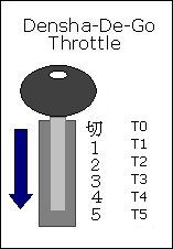
| Throttle Position | X | Y | Z |
|---|---|---|---|
| T0 | [x] | [x] | |
| T1 | [x] | [x] | |
| T2 | [x] | ||
| T3 | [x] | [x] | |
| T4 | [x] | ||
| T5 | [x] |
| Other Buttons | Mapping |
|---|---|
| SELECT | D |
| START | START |
| A | A |
| B | ?? |
| C | C |
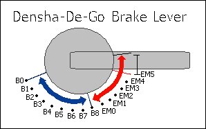
| Brake Position | UP | DOWN | LEFT | RIGHT |
|---|---|---|---|---|
| B0 | [x] | [x] | [x] | |
| B1 | [x] | [x] | [x] | |
| B2 | [x] | [x] | ||
| B3 | [x] | [x] | [x] | |
| B4 | [x] | [x] | ||
| B5 | [x] | [x] | ||
| B6 | [x] | |||
| B7 | [x] | [x] | [x] | |
| B8 | [x] | [x] | ||
| EM0 | [x] | [x] | ||
| EM1 | [x] | |||
| EM2 | [x] | [x] | ||
| EM3 | [x] | |||
| EM4 | [x] | |||
| EM5 | - | - | - | - |
In between the B's there is a slight overlap of the buttons, where the current and next 'combination' is combined, but this doesn't seem to last more than one cycle.
In between the EM's the controller reads UP-DOWN-LEFT-RIGHT. This area exists between all EM's and B8-EM0 and seems to be about 3mm wide.
Controlling trains
Now it was time to get this incorporated into my original train throttle. I didn't want to have to use the Python code, so instead I 'crafted' the packets into the Arduino code.
	//here is a quick packet to request device information from controller 'one'.
	//i.e. the only controller connected.
	packet.header[0] = 0; // Number of additional words in frame
	packet.header[1] = 0; // Sender address = Dreamcast
	packet.header[2] = (1 << 5); //(1 << 5); // Recipient address = main peripheral on port 0
	packet.header[3] = 1; // Command = request device information
	packet.data[0]   = 0x21; //checksum
	packet.data_len  = 5;
	//send the above packet to initiate comms with the controller.
	maple_transact();
I'm going to gloss over this part pretty quickly, as this post was more about getting the Dreamcast controller usable rather than another lesson in physics and model railway throttles. For the code, I ended up just deciphering the packet that comes back from the controller, working out what the throttle position is and then adjusting the target speed. The main program loop then makes then increment/decrements the current speed to eventually match the target speed. This provides a very simple form of acceleration.
void control_throttle(void) {
	//quick hack, should actually do a binary 'and'
	//packet data[6] contains the throttle position, so use this to gauge
	//voltage output to pin 7 (or speed)
	switch (packet.data[6]) {
		case 0xF9: target_speed = 0;	t_pos = 0; break;
		case 0xFA: target_speed = 88;	t_pos = 1; break;
		case 0xFB: target_speed = 96;	t_pos = 2; break;
		case 0xFC: target_speed = 140;	t_pos = 3; break;
		case 0xFD: target_speed = 190;	t_pos = 4; break;
		case 0xFE: target_speed = 250;	t_pos = 5; break;
	}
}
The changing of pin 13 below lights the on-board Arduino LED to show once the loop has made the speed match the target speed.
	digitalWrite(13, LOW);
	if (target_speed > speed) {
		//accel
		speed += t_pos / 2;
	} else if (target_speed < speed) {
		//speed += abs(target_speed - speed);
		//decel
		speed--;
	} else {
		digitalWrite(13, HIGH);
	}
	//send the speed to the pin/railway
	analogWrite(7, speed);
And then... it just worked :)
 Download the source code here.
Note that this does not include the Python code; nor will my code correctly interact with the python code anymore. The goal was always to have the Arduino talk to the Dreamcast controller directly.
As you can see, I've only implemented the throttle on the controller... I need to now bring in the brake lever as well, but this is where the physics lesson comes in. I'll be posting again soon enough with source code for acceleration and braking using this controller.
I've got a few ideas as to how to semi-realistically control the train with both levers, but I will need to do a little more reading before I get something going. I do know that in the actual Densha-De-Go game, the game complains when you have both levers on at the same time... and it seems wrong to be doing so... but then again, it'd be like doing a hill-start :) Maybe for freight trains?
If only our model railway trains had gears and could free roll!
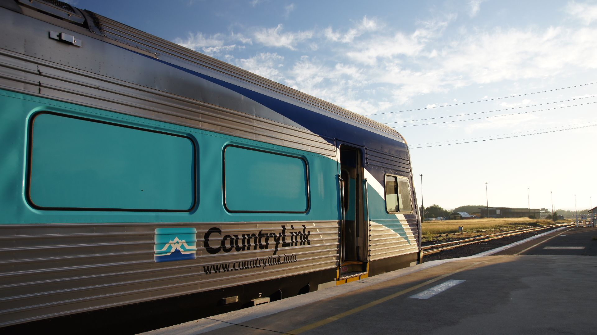
Canberra to Queensland
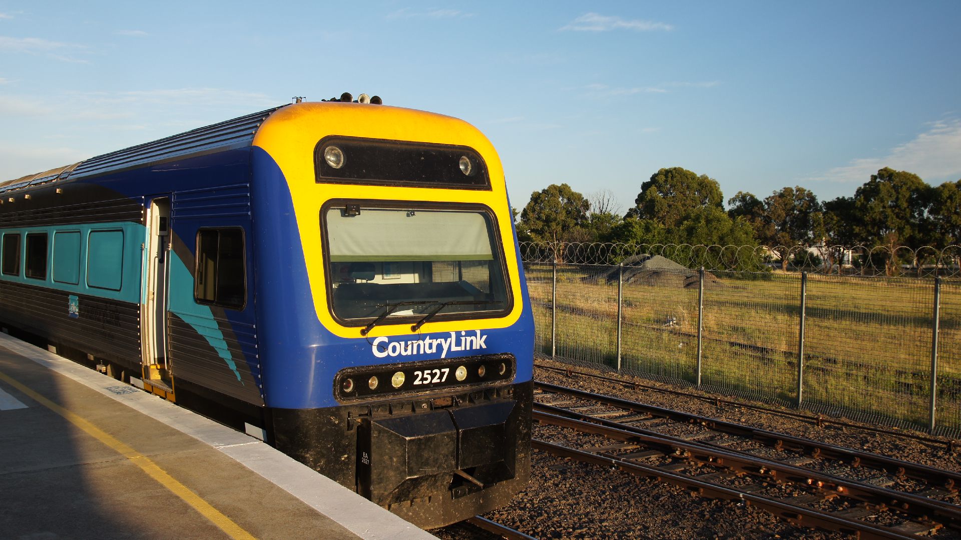
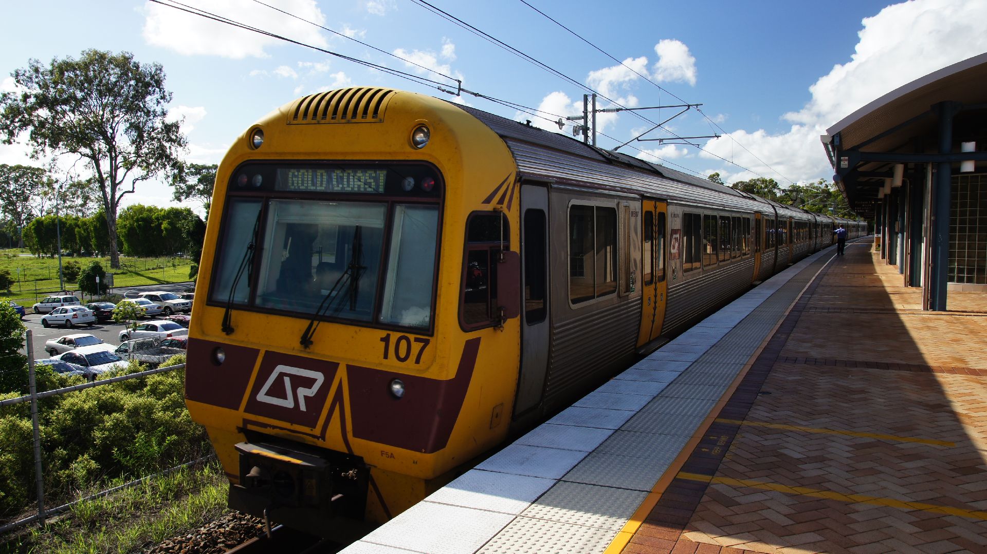
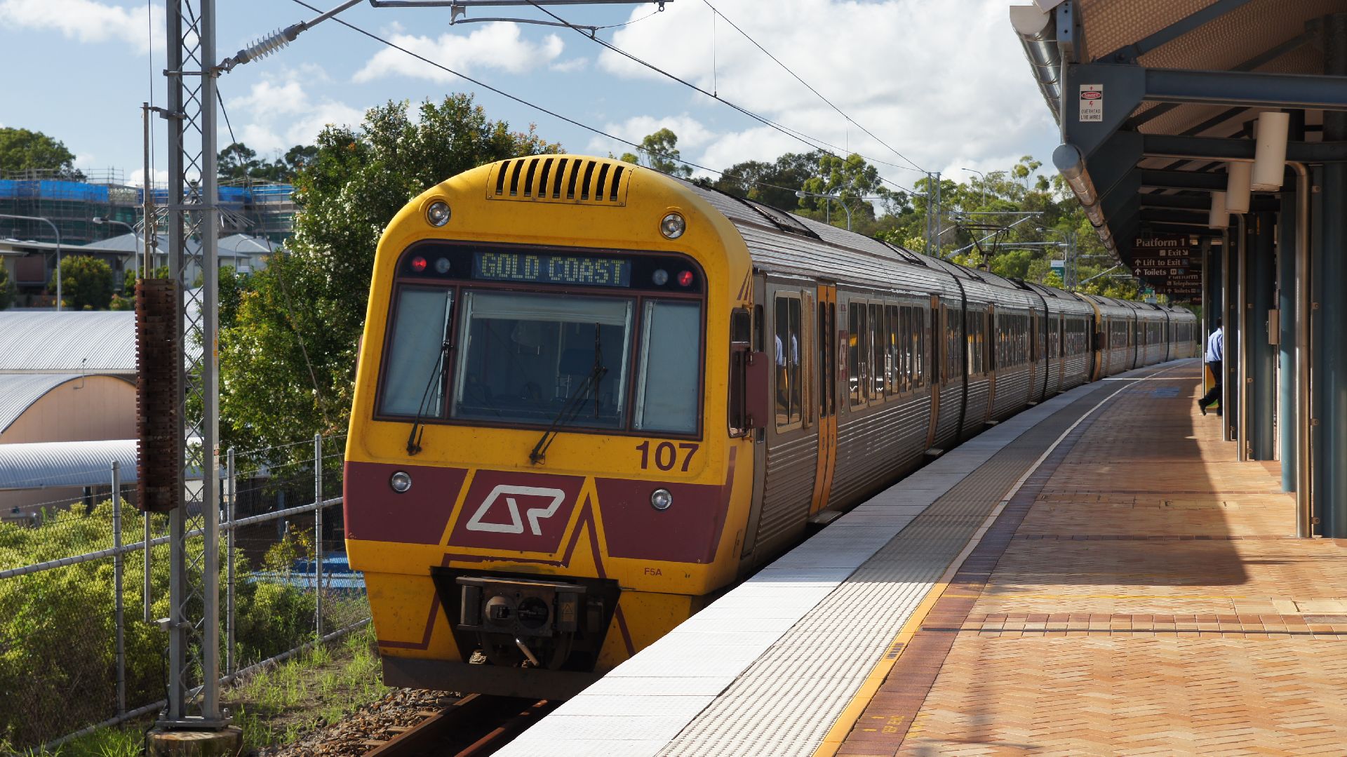
I'd been invlted to the Gold Coast for NYE 2010 and so I thought I'd make an adventure of it and go by rail. Google Maps indicated that, via the Pacific Highway, the distance is 1,130km and, by car, it would have taken around 14 hours. I wasn't going for a land-speed record (and this isn't Japan) so I decided to take a relaxed path via Country Link (which does happen to be the only regional rail transport that travels north nationally.) This trip was to go via Sydney, Maitland (the start of the Hunter Valley) and then the north coast (overnight) to Brisbane. I could have chosen to switch to a bus at Grafton/Casino, but I didn't feel like changing transport at some gawd-awful time in the morning and a bus didn't appeal to me. After arriving at Brisbane early in the morning, I was to change to QR and travel south to the Gold Coast, arriving around 8:00am.
Canberra
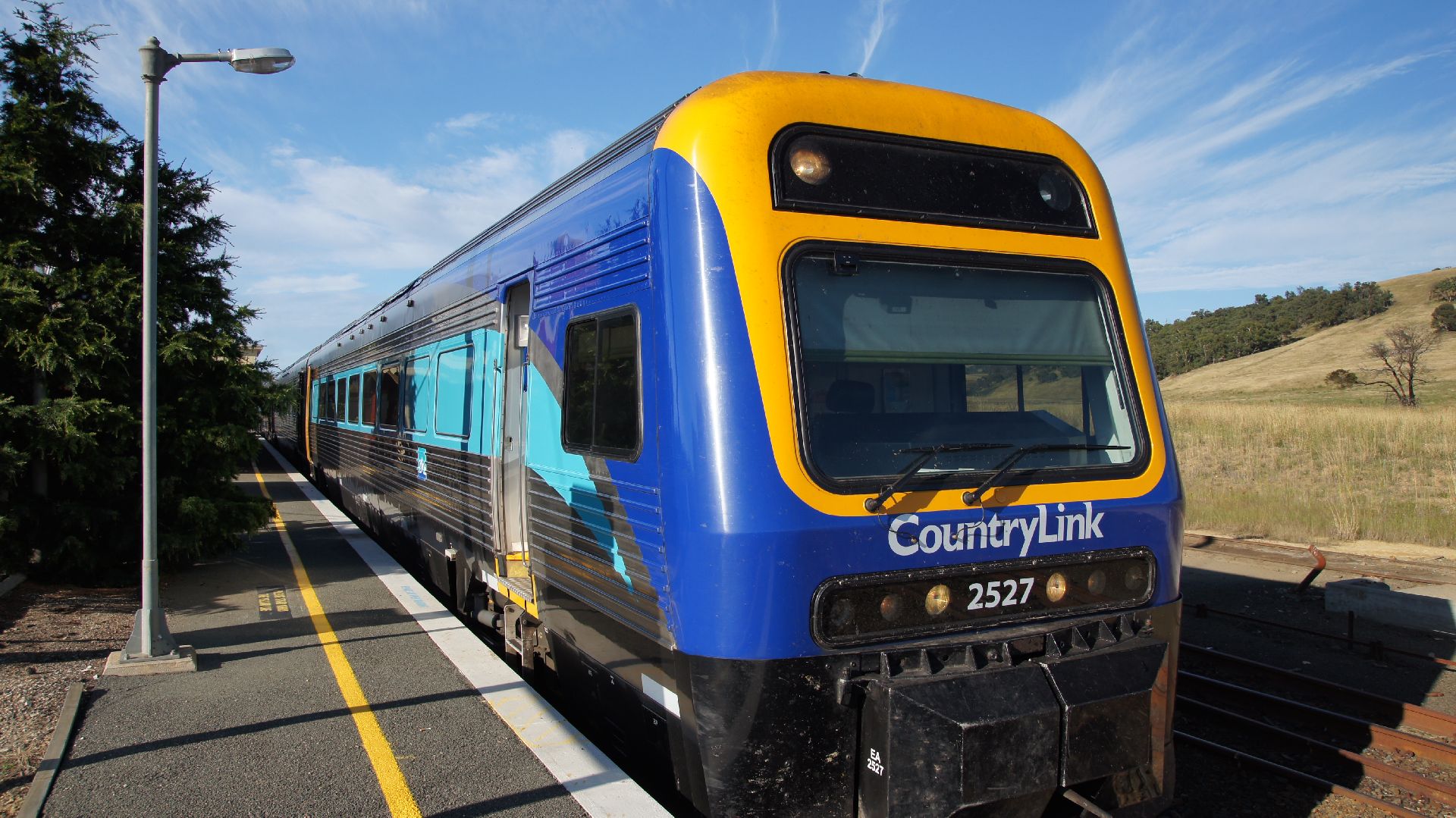
This trip started early at Kingston Railway Station in Canberra, ACT on Wednesday the 29th of December. This station (note that we are in Australia's capital) sees no more than 3 passenger train departures per day and 3 arrivals. These are even staggered so that every second day you can leave in the morning and afternoon, alternately with morning and evening on other days. Randomly inconvenient and it gets worse; the trip to Sydney (Central Station) takes around 4.5 hours. Meanwhile, if you are wanting to buy tickets for Country Link trains, I can only recommend to purchase them at Queanbeyan Station as it's run by the staff of the ARHS ACT and they get a commission.
Either way, we got off on time and stopped at Queanbeyan 10 minutes after leaving Canberra.
We then arrived at Bungendore around 30minutes later. As I had worked on the ARHS ACT trains, I knew I had enough time to grab a few photos as the whole line from Canberra to Goulburn still uses the 'staff' system. This meant that the driver had to exchange staffs in each of the signal boxes along the way.
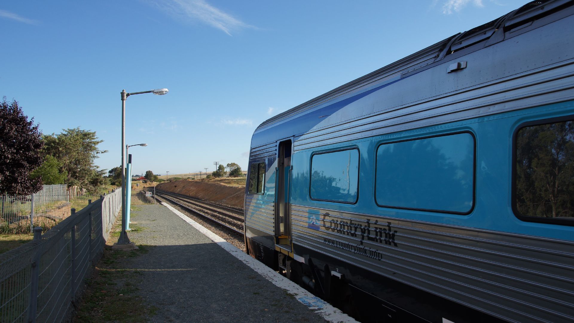

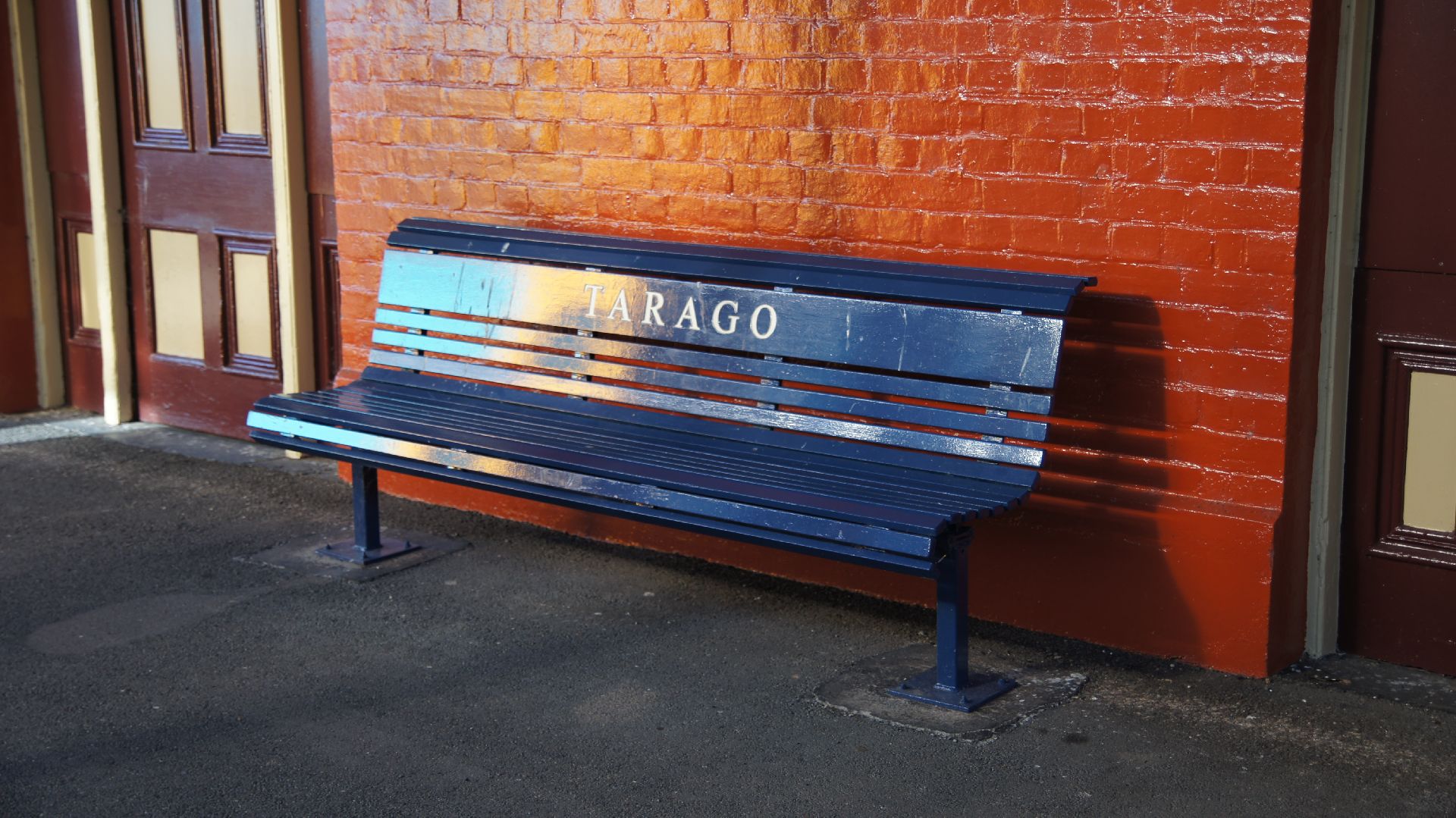
At Tarago, the same thing had to happen and so I checked out the station. This was the final station on the Goulburn-Canberra branch before the train was to enter the "Main South". After this there were not going to be many other photo opportunities.
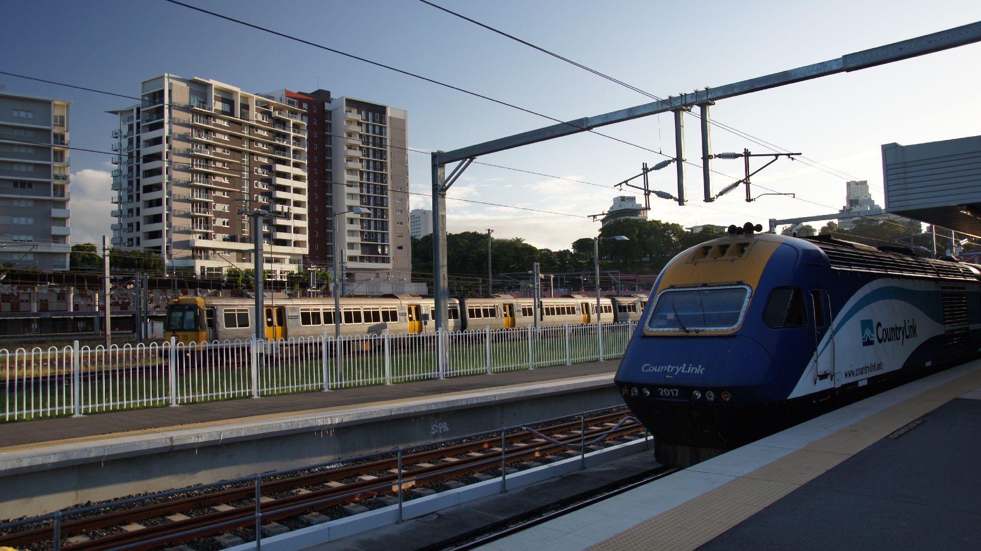
Sydney (aka. CityRail)
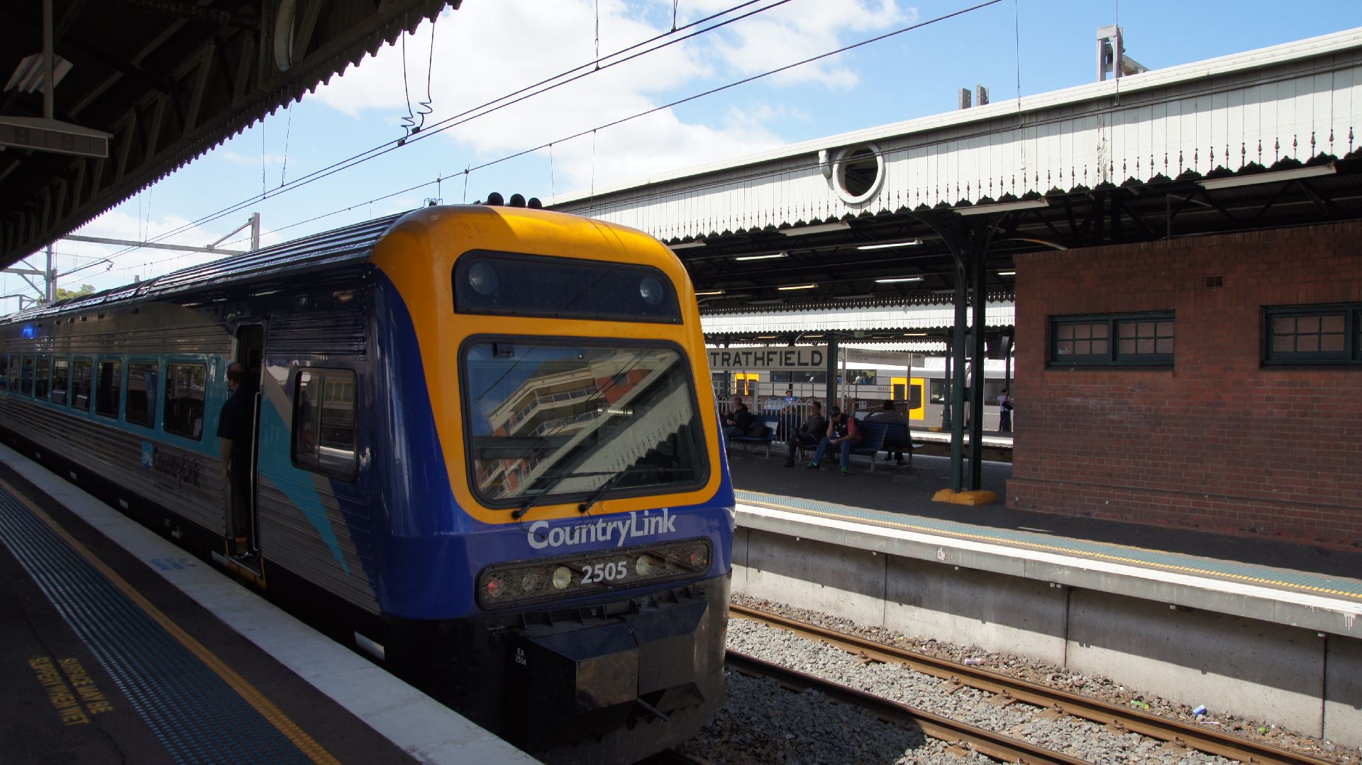
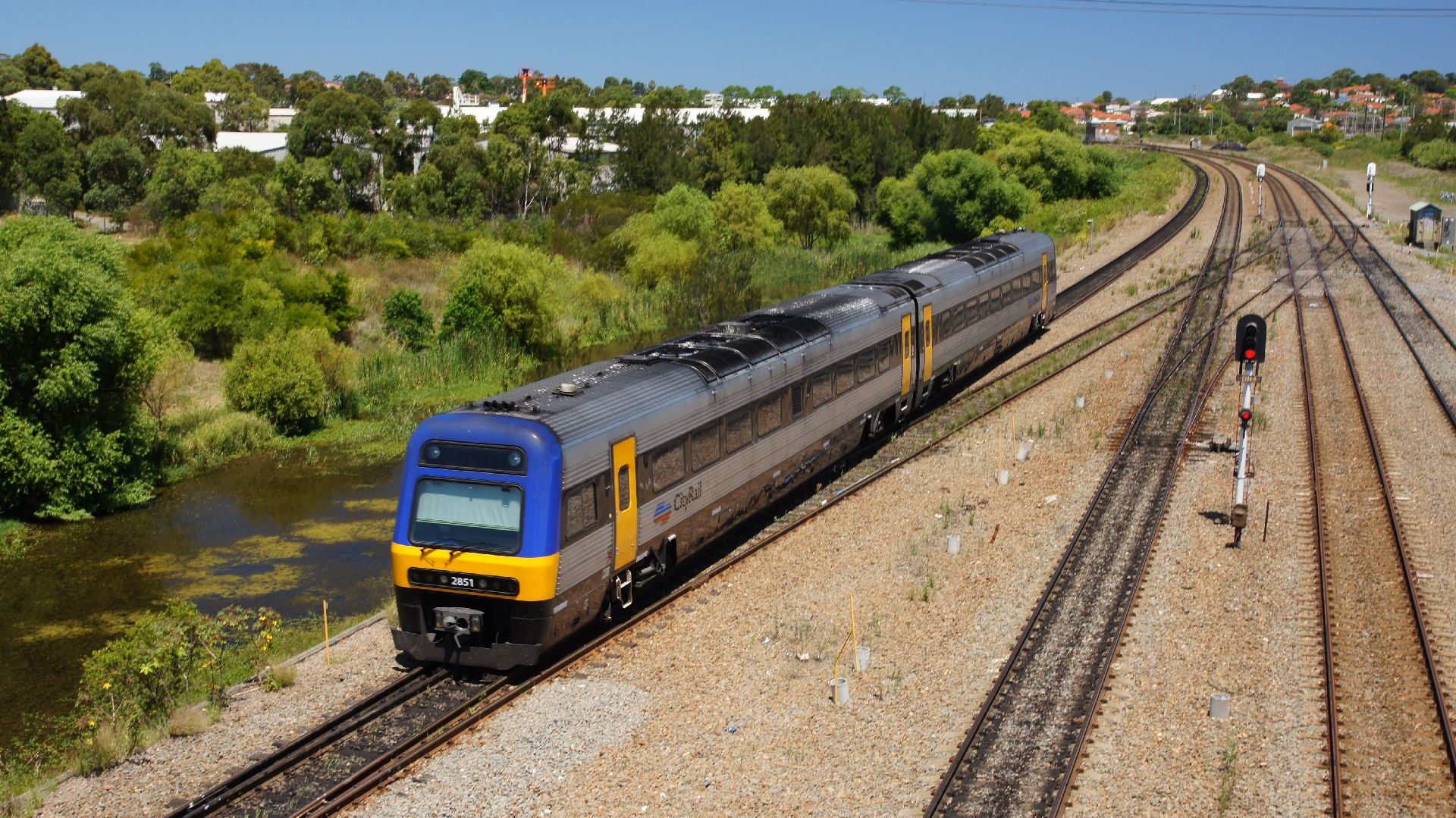
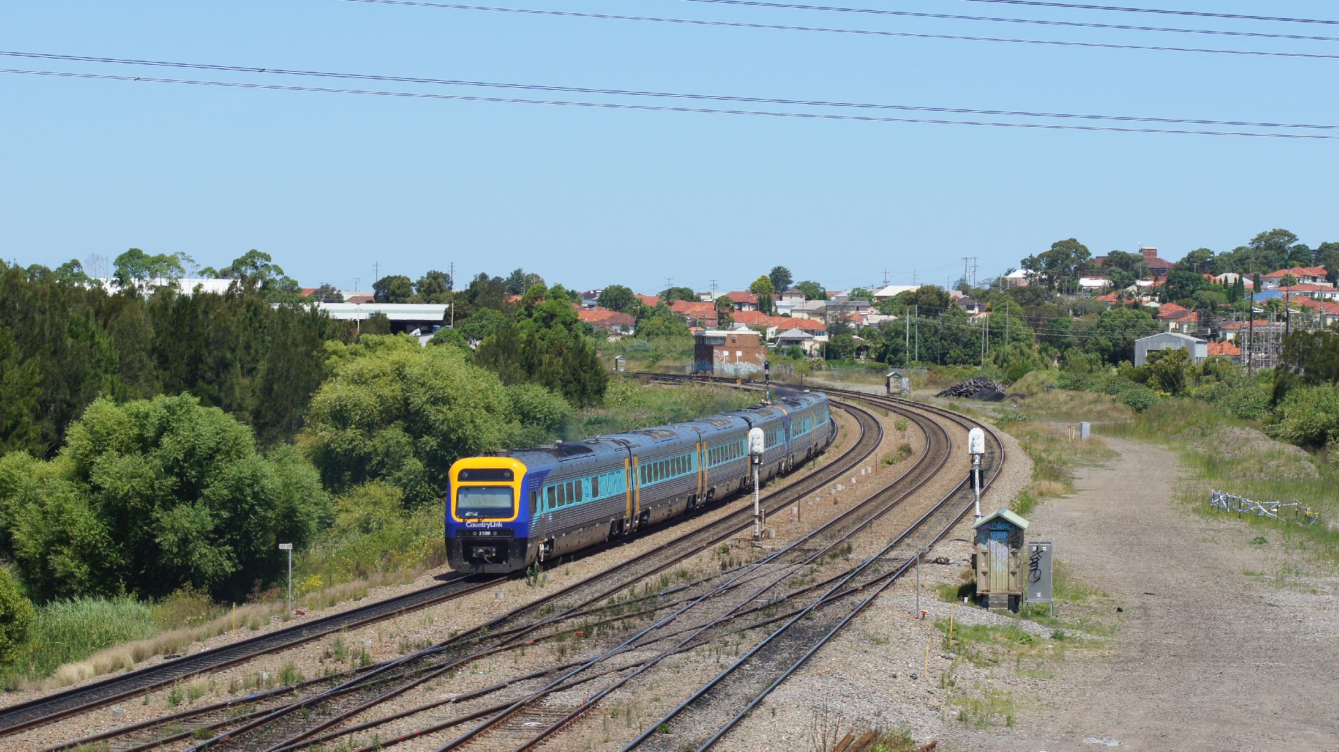
We arrived at Strathfield Station at some time after 10:00am after leaving Canberra at 6:43am. I then had about 6 minutes to change platforms and get onto a northbound express service. This service was to be run by CityRail which is the Sydney electric train network operator. They also run DMU services on non-electrified track.
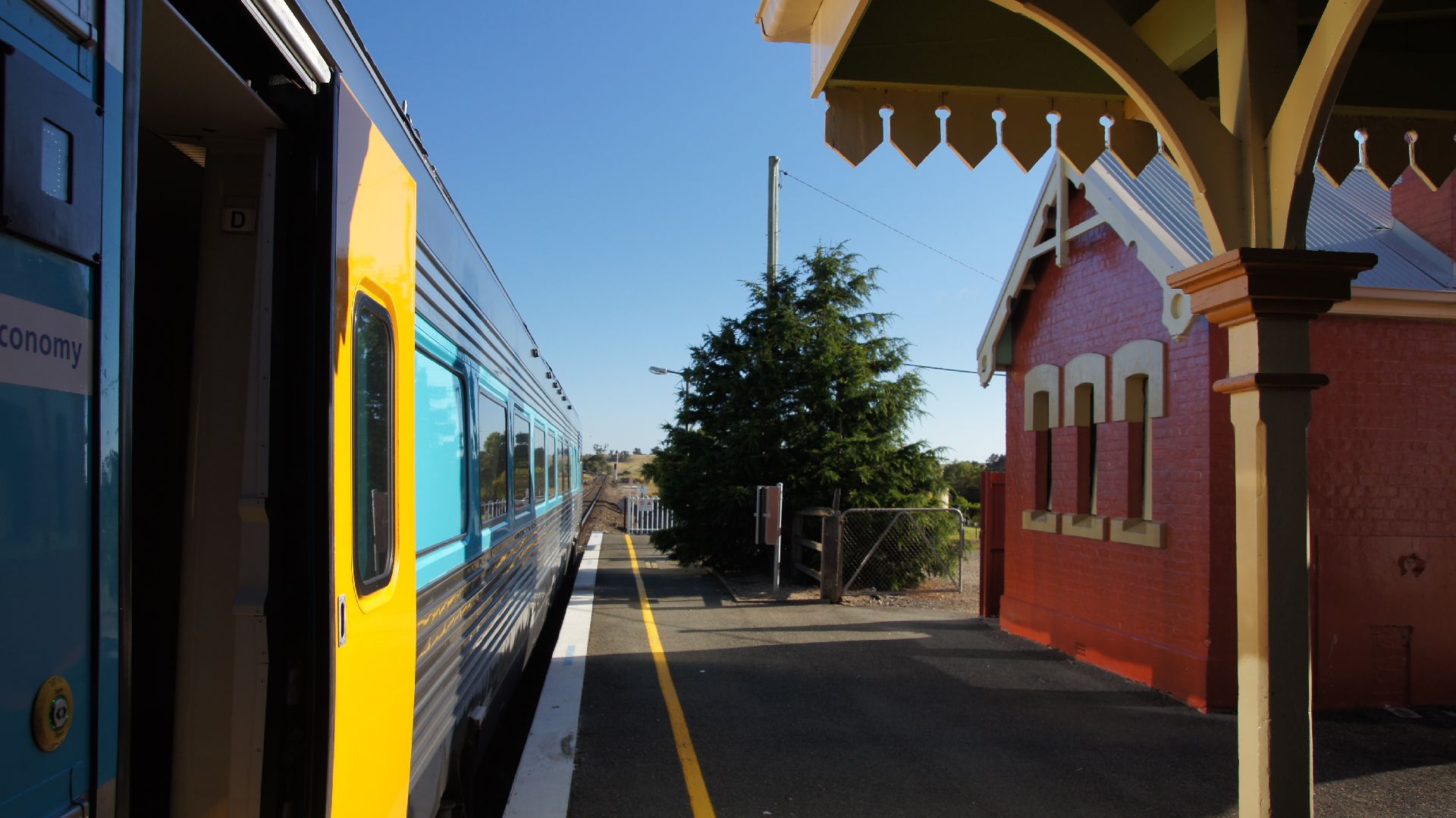
This northbound train was to terminate at Wyong, but that was good enough, as I knew that there were freight services running over the "Main North" to keep me entertained there. I'd stopped by Wyong around 3 years ago and had seen a nice couple of RLs carrying freight southbound... unfortunately, we were well short of Wyong when the freighter stormed past, doing a great speed up the Cowan bank.
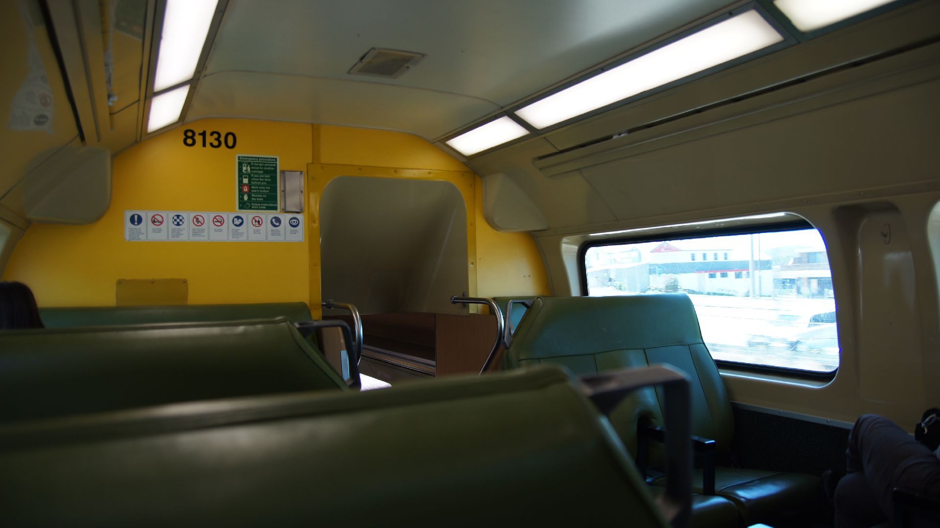
The CityRail fleet consists of all sorts of electric trains, but the northbound long-distance routes are covered by "V" sets (I believe) and they are ancient... Fortunately they are extremely comfortable and are even decked out with toilets and mildly-functioning air-conditioning. Really quite retro!
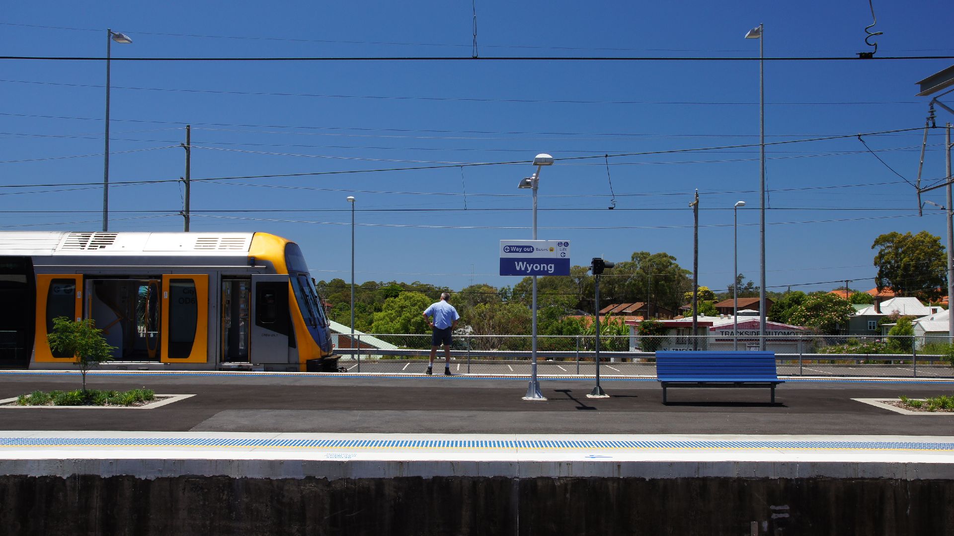
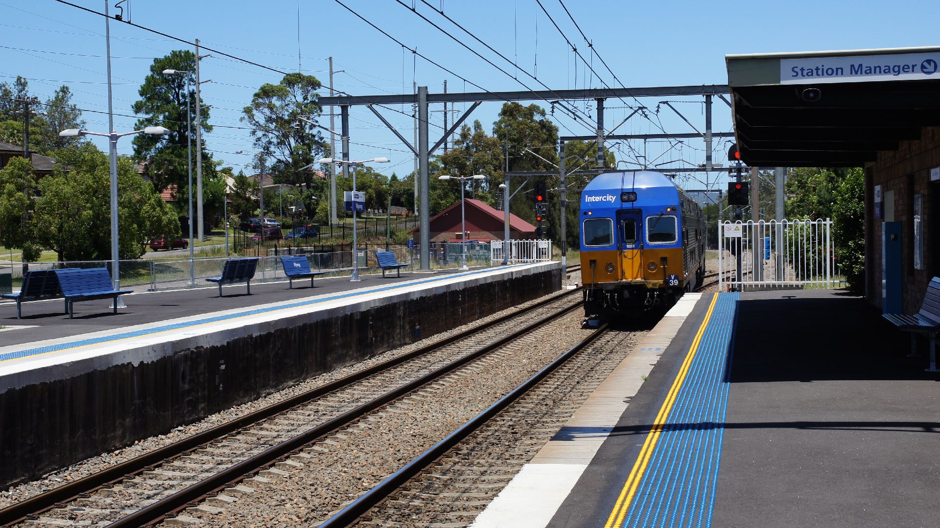
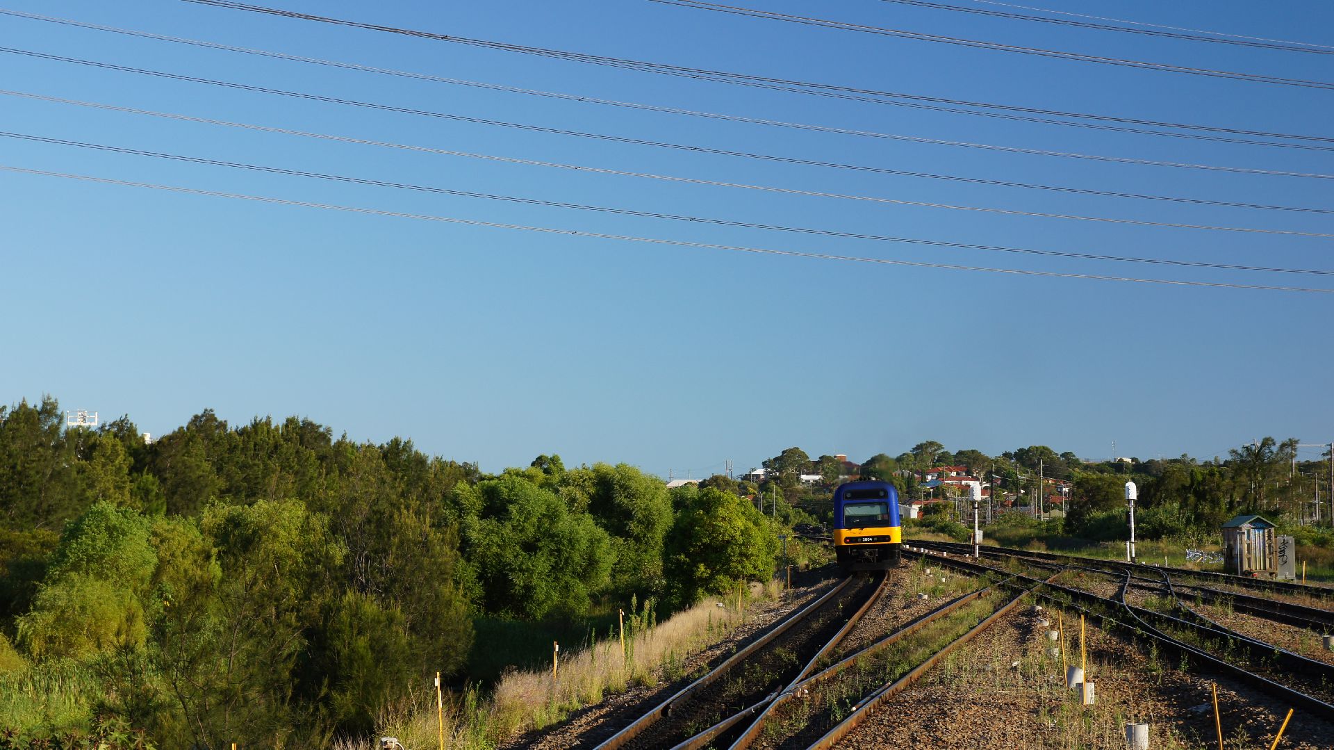
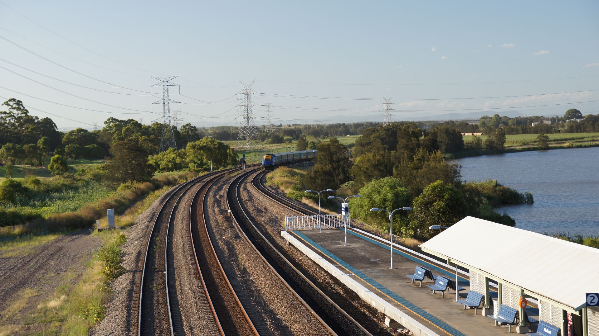
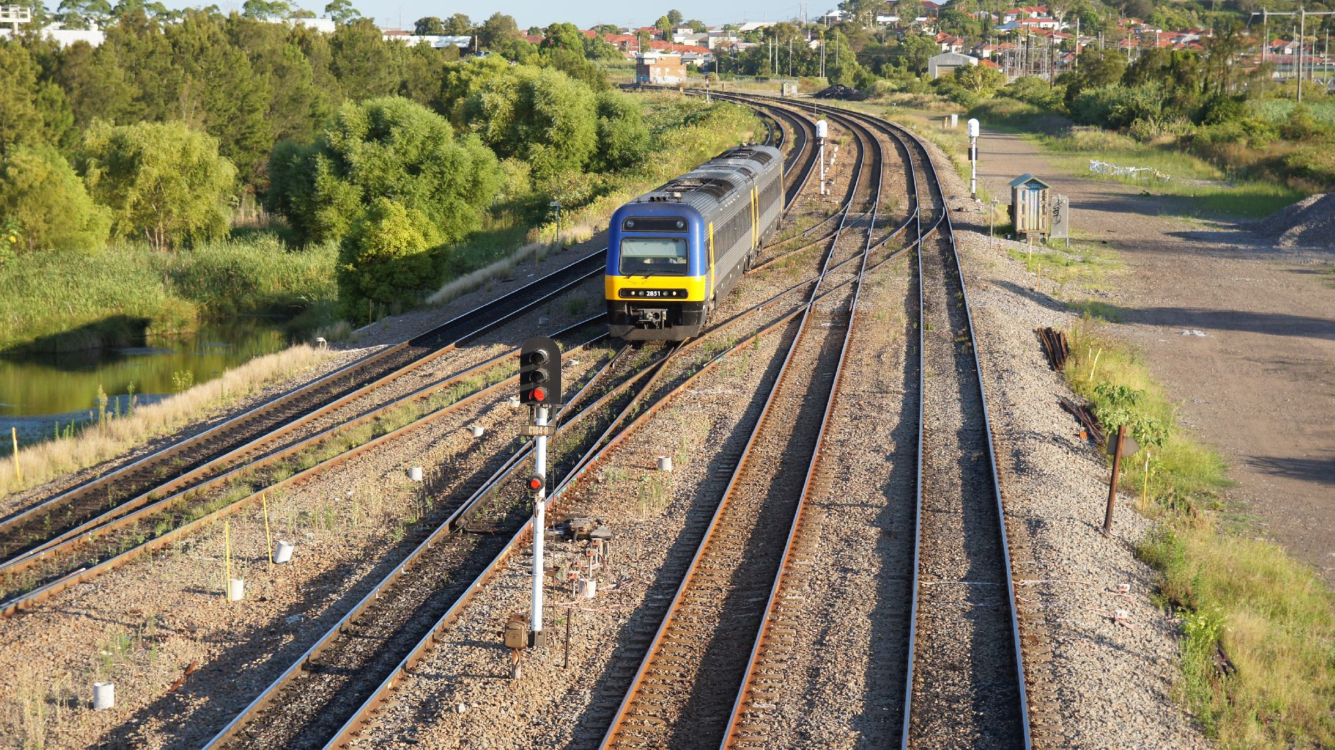
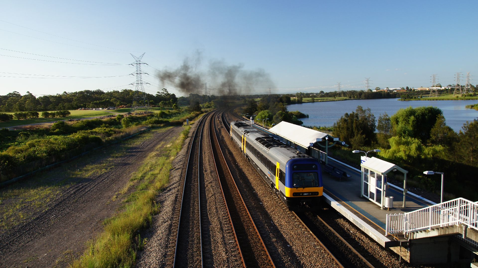
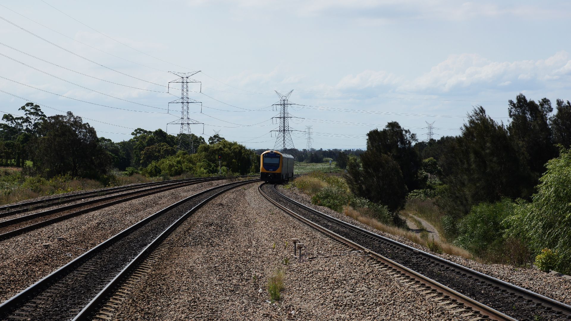
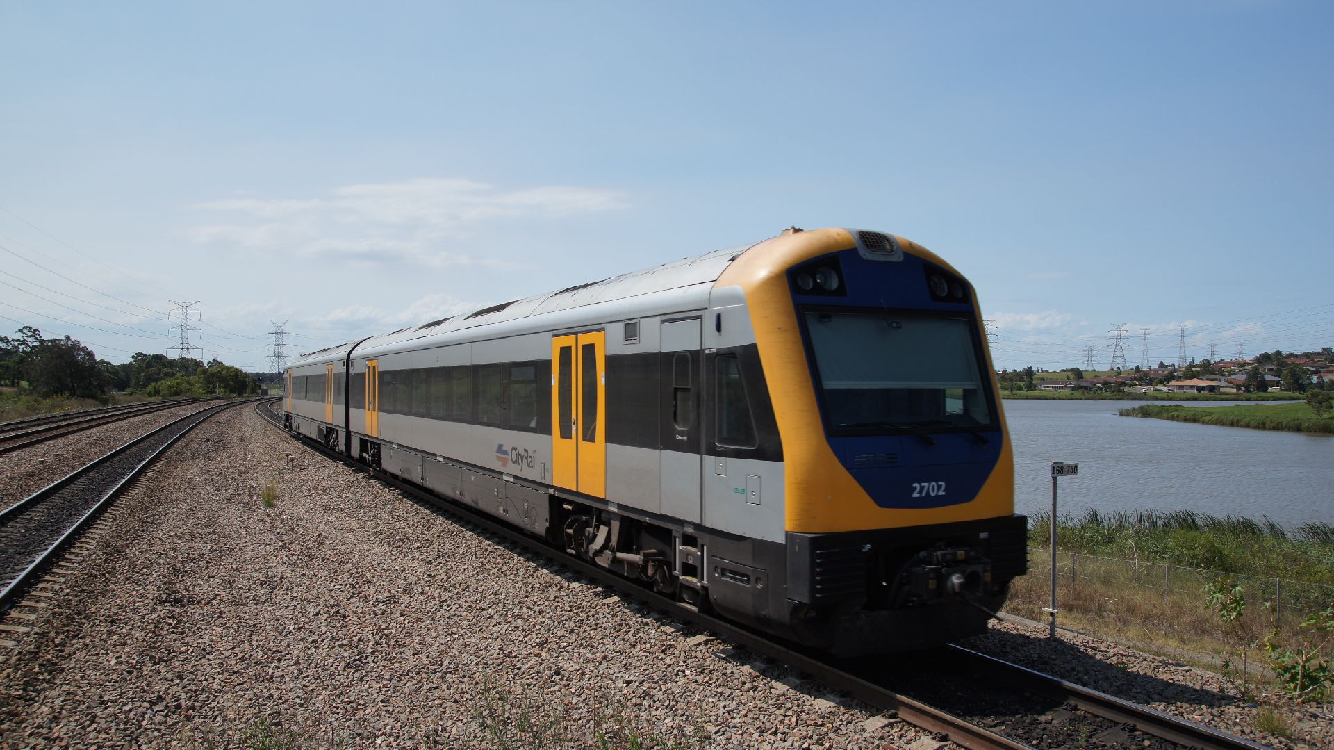
I therefore got off at Wyong and waited for the next service to Newcastle. I would only travel as far as Hamilton which is three stops before Newcastle and is the first station which intersects with the Hunter Line. Here I would transfer and then travel on the diesel service to Victoria Street where I was to stay overnight.
The DMUs used on the Hunter Line are two-car and I think nearly everyone of them had a flat-spot on one wheel somewhere.
Maitland and surrounds
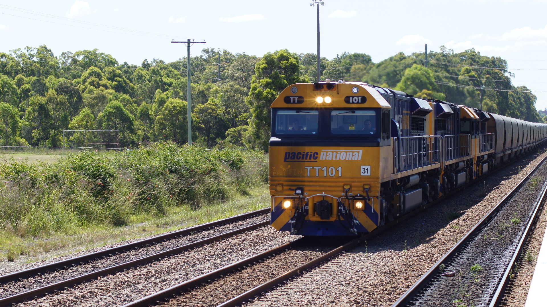
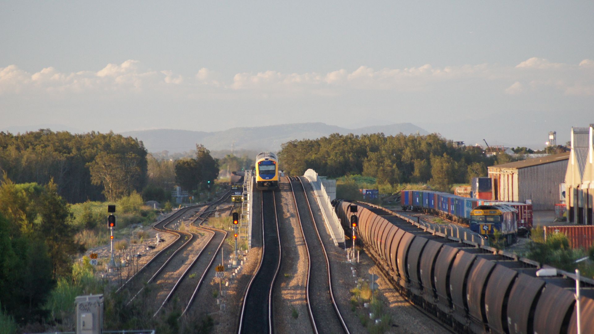
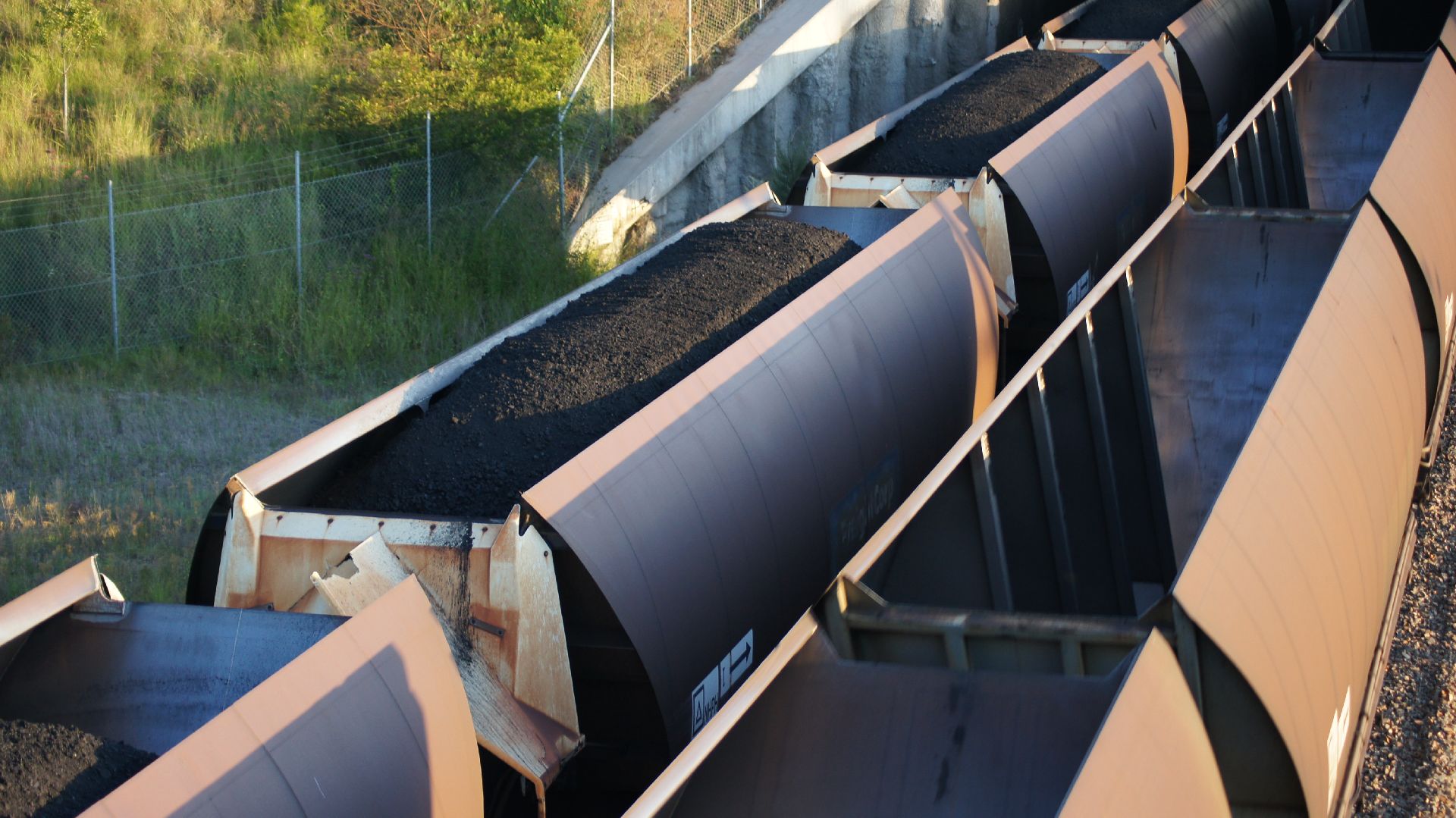
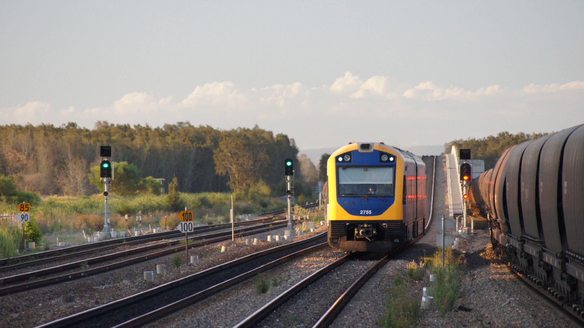
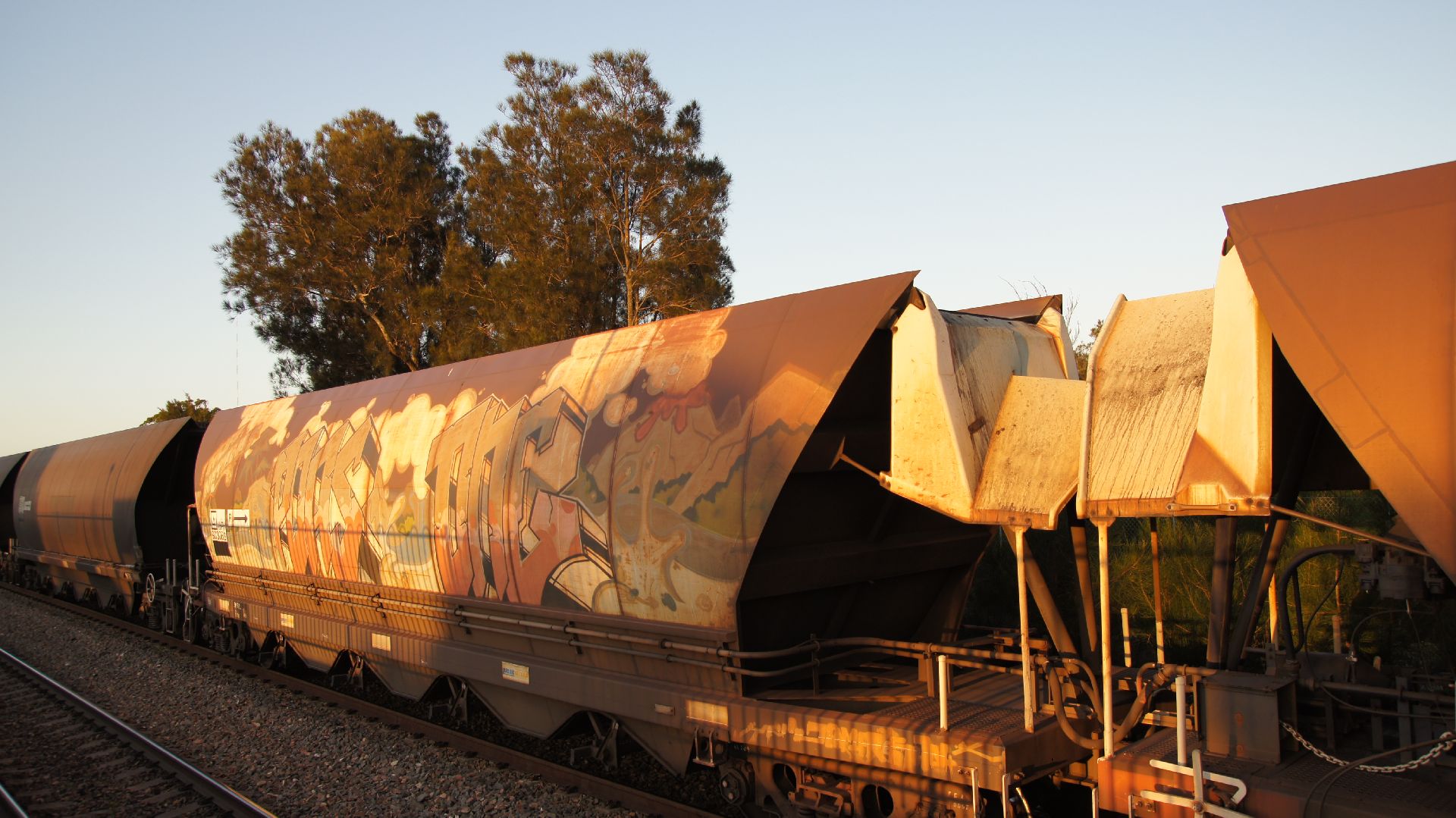
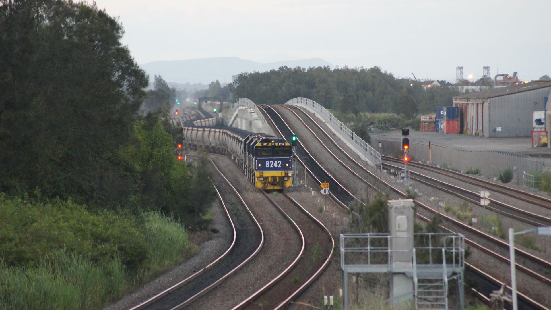
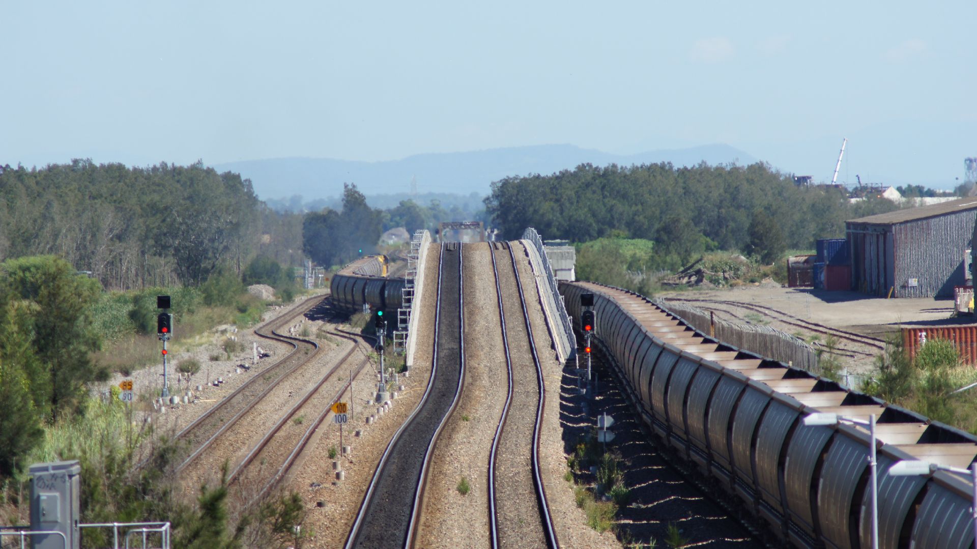
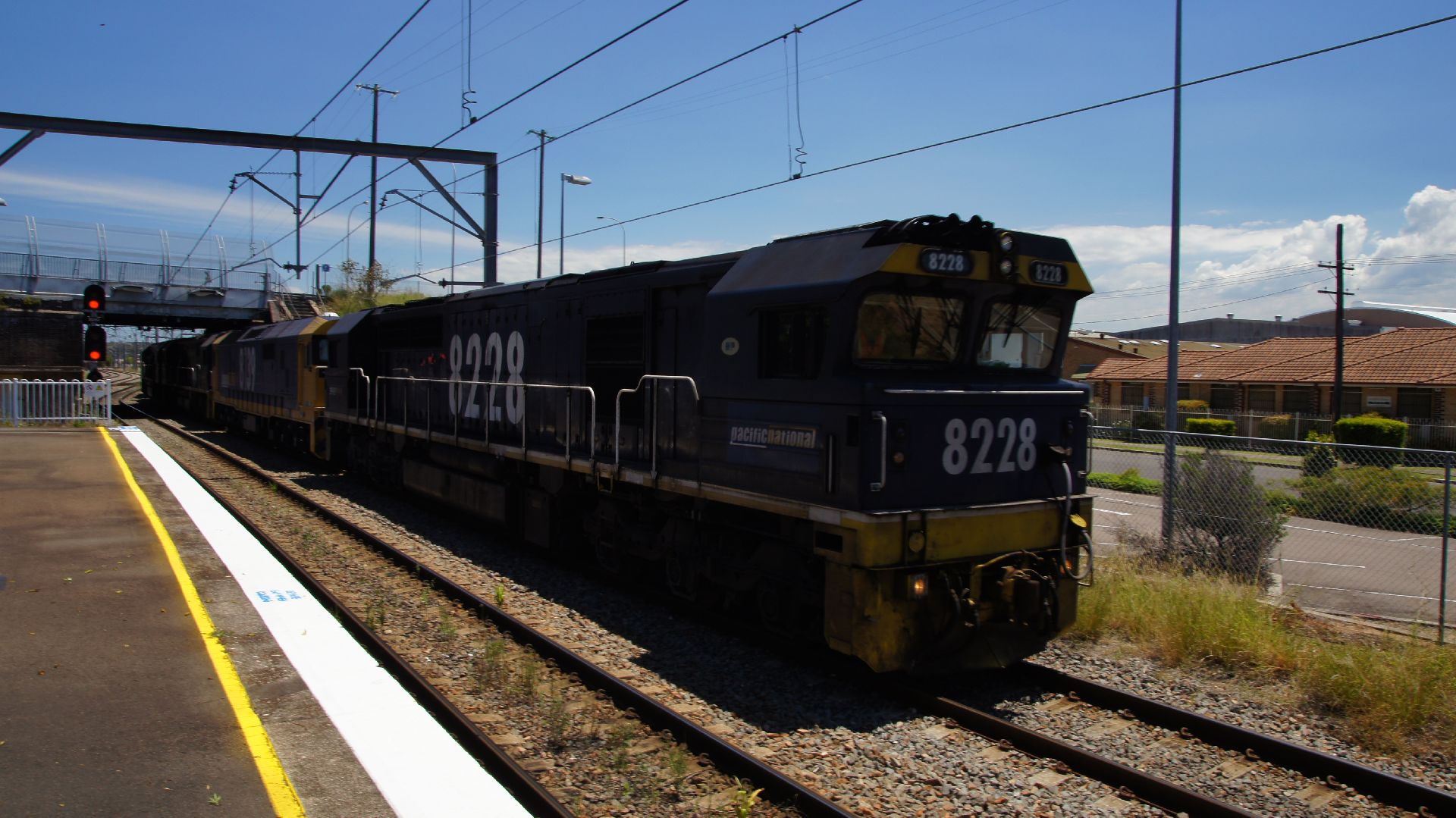
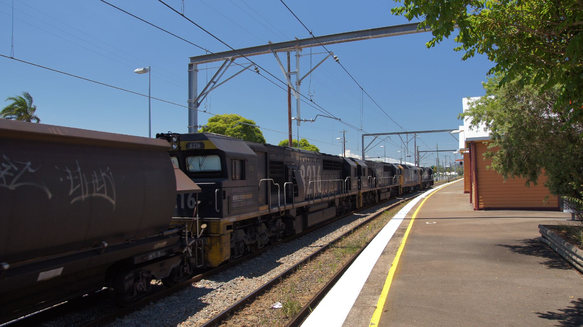
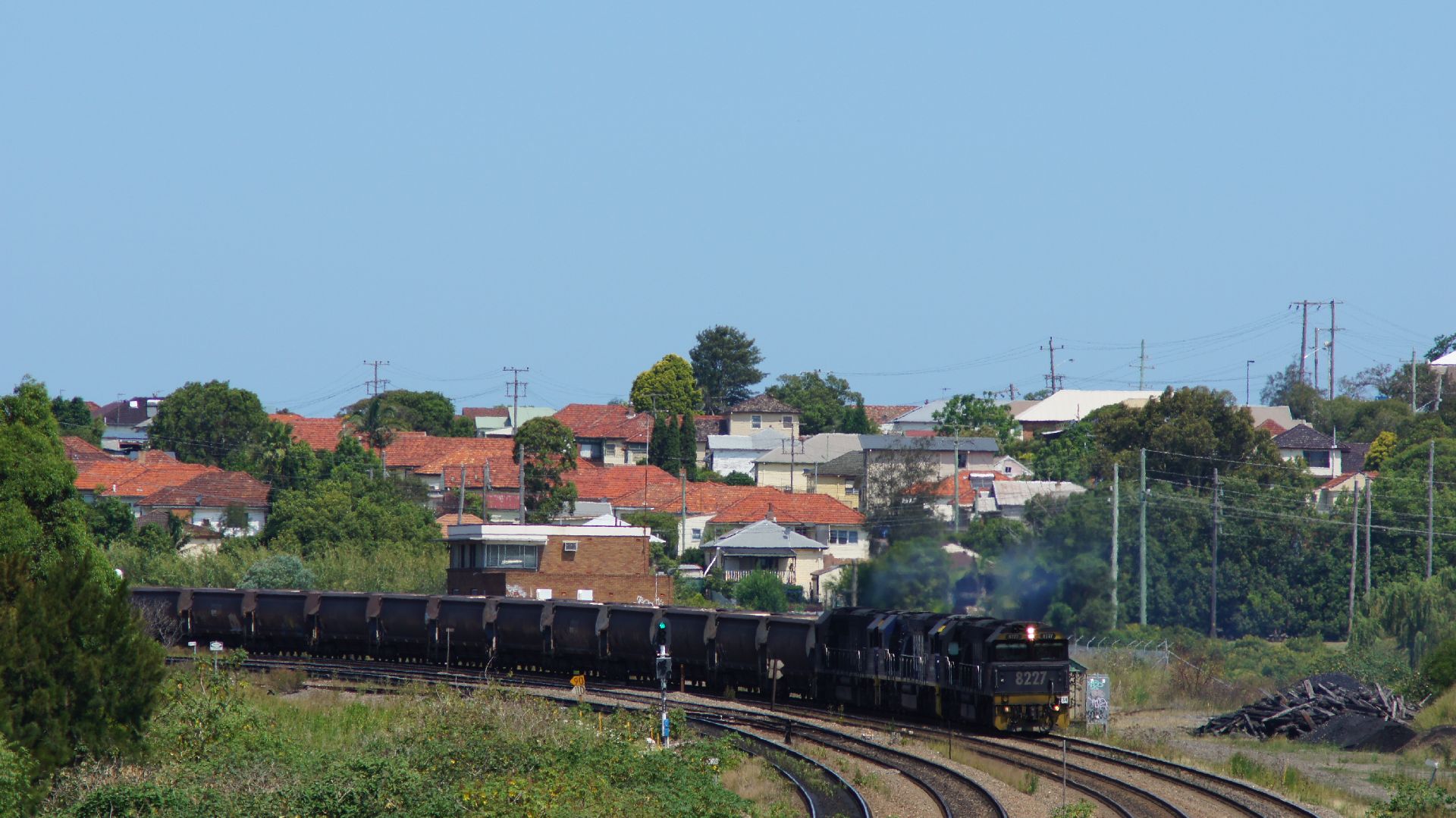
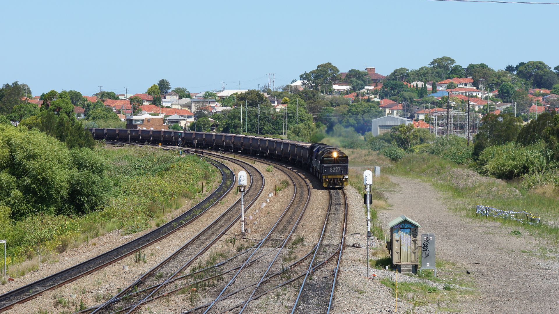
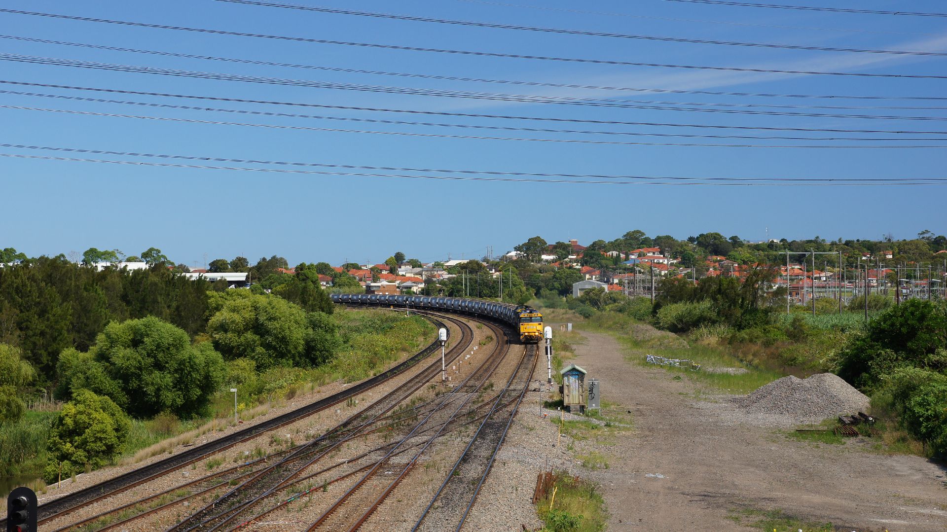
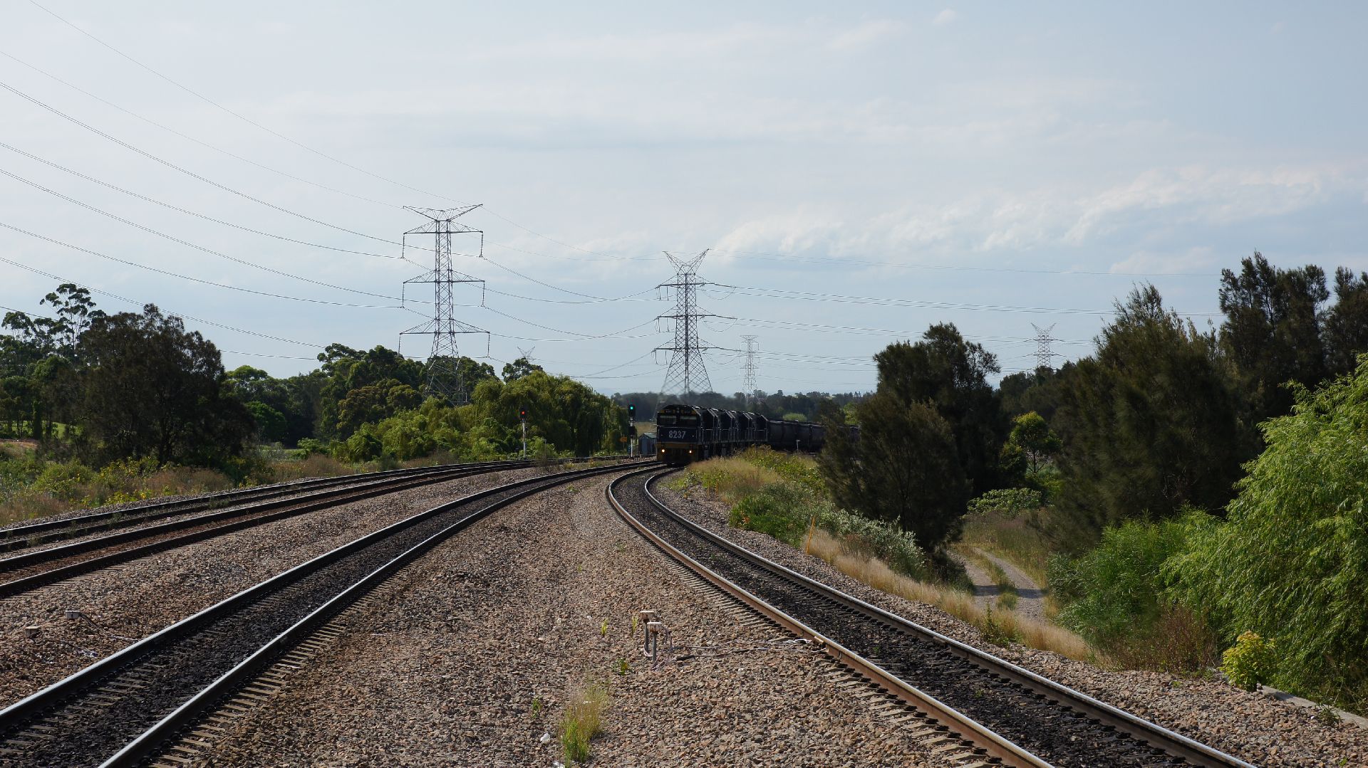
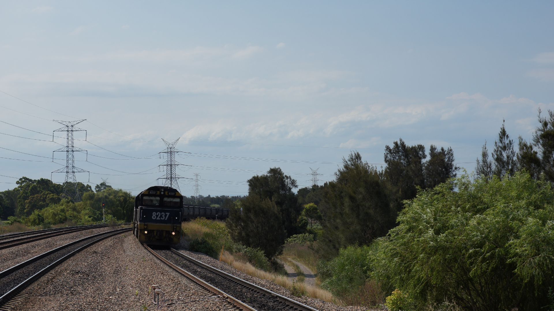
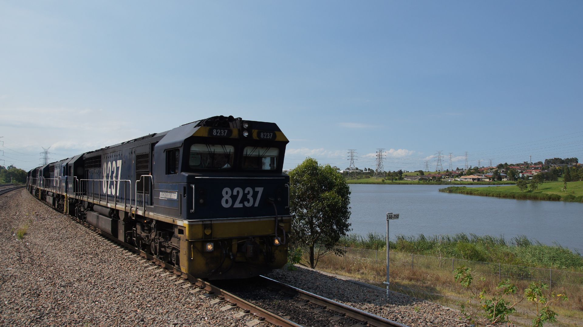
Now, once in the heart of coal-country, it wasn't going to be too long until a coal train was to come hurtling past; it ended up being three, straight after each other. From what I gathered, the trains gave around 10 minutes minimum between each other when travelling in the same direction; but the paths were already clear well before.
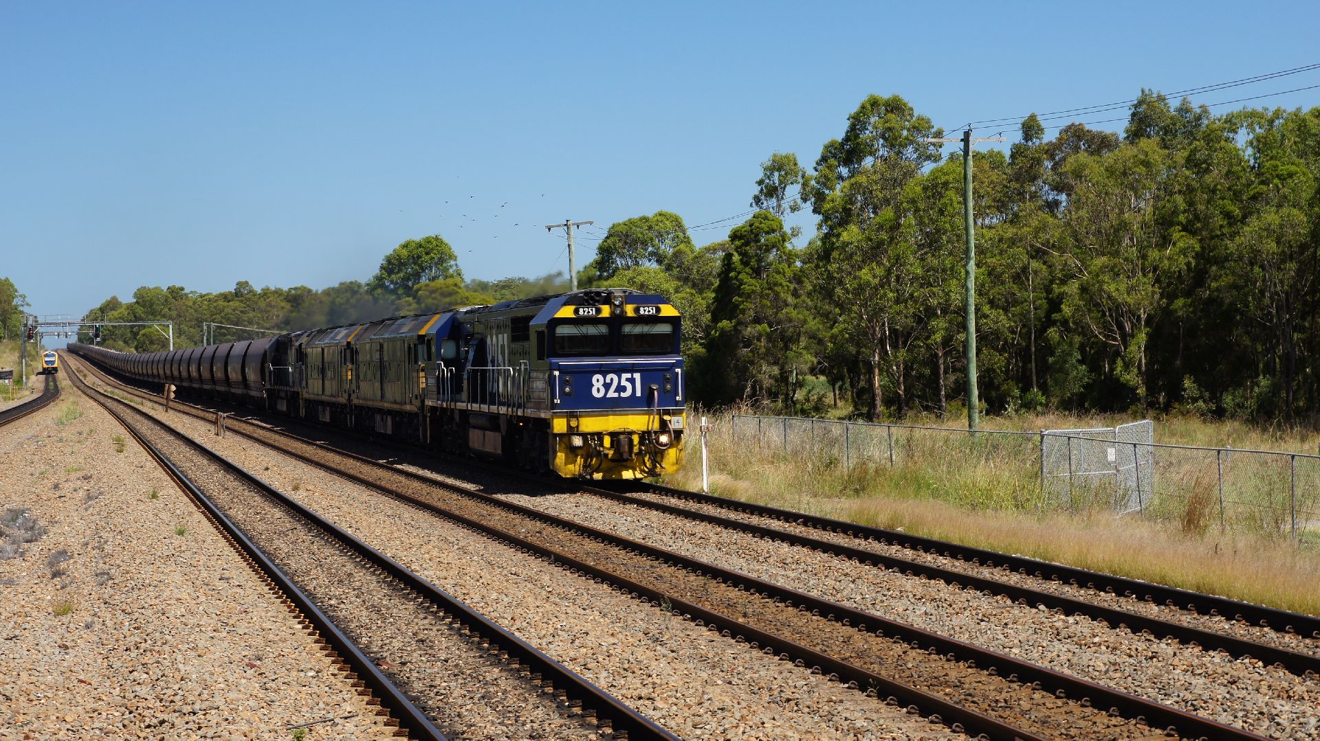
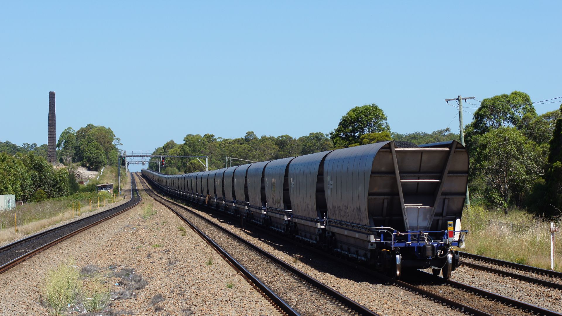
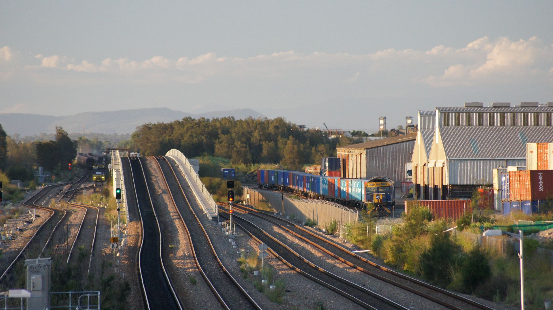
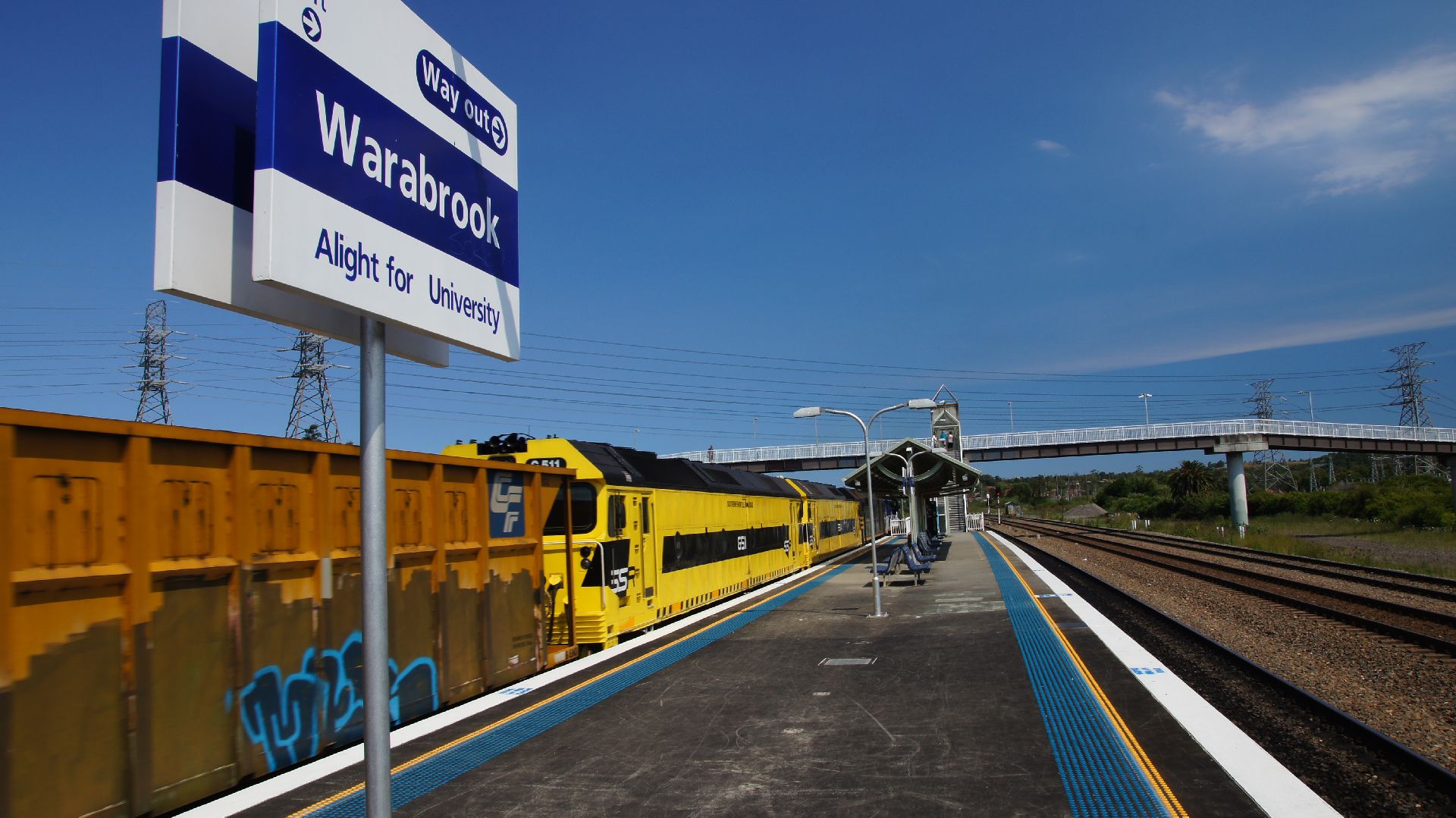
After realising I could see coal trains all day, I packed up the camera and checked in to my hotel. Once settled, I then headed back to Warabrook Station and checked out the action. This station is located between Islington Junction and the other triangle (Koogarang Junction?)... although the double-triangle is probably known as Islington Junction. Either way, coal trains would be entering from all directions and I wasn't disappointed.
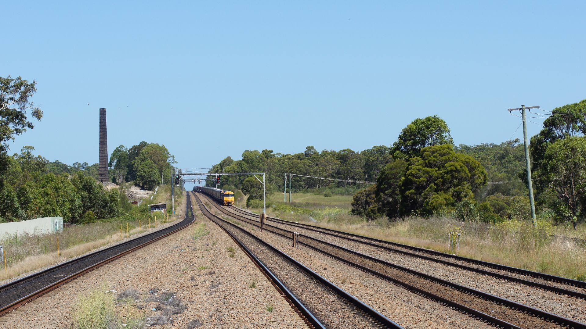
So, random light engine movements, but no coal trains... it turns out I could see them, but none were coming from the Newcastle direction. I therefore jumped on the next westbound train and got off at the next station past the triangle: Sandgate.
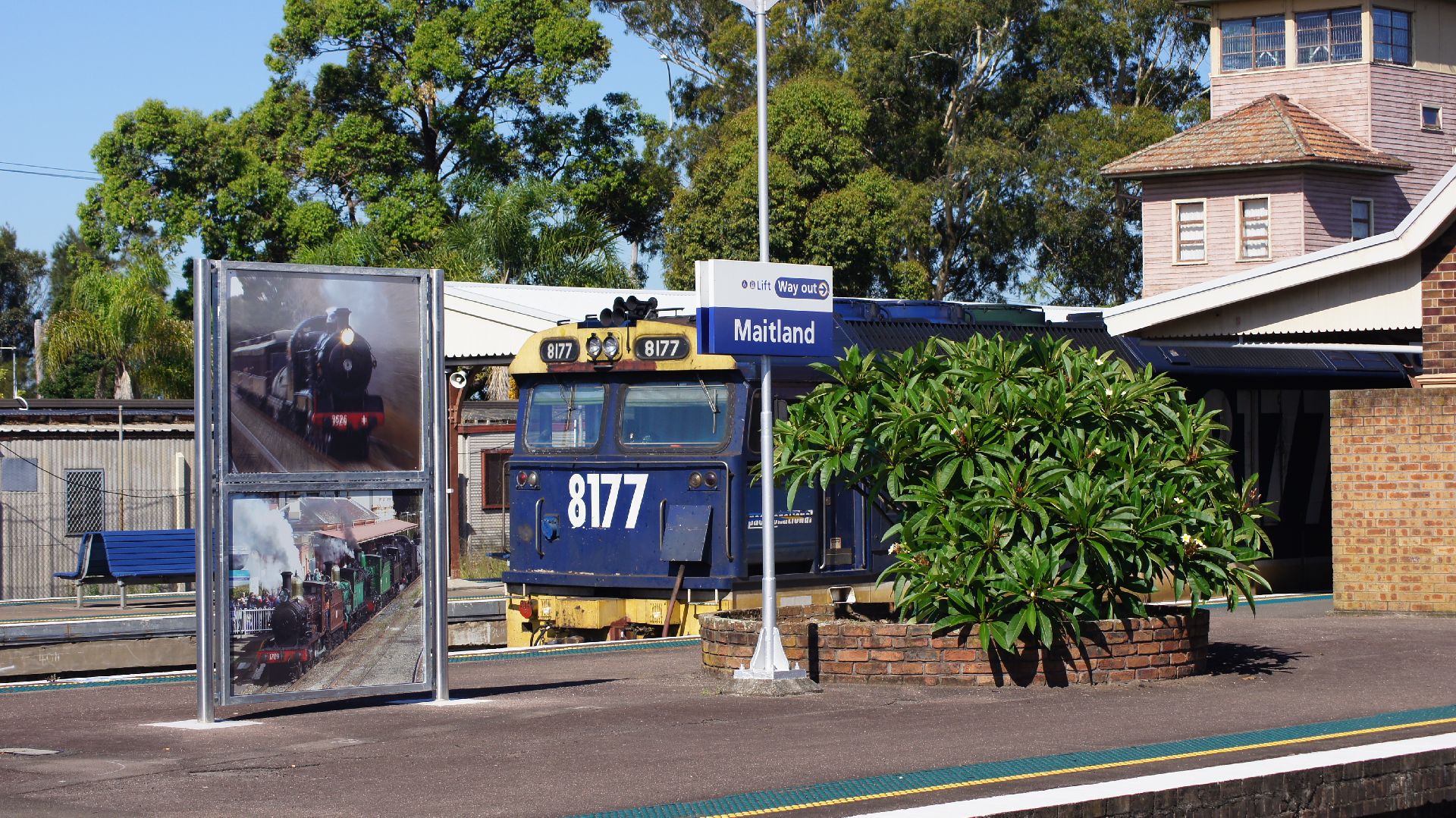
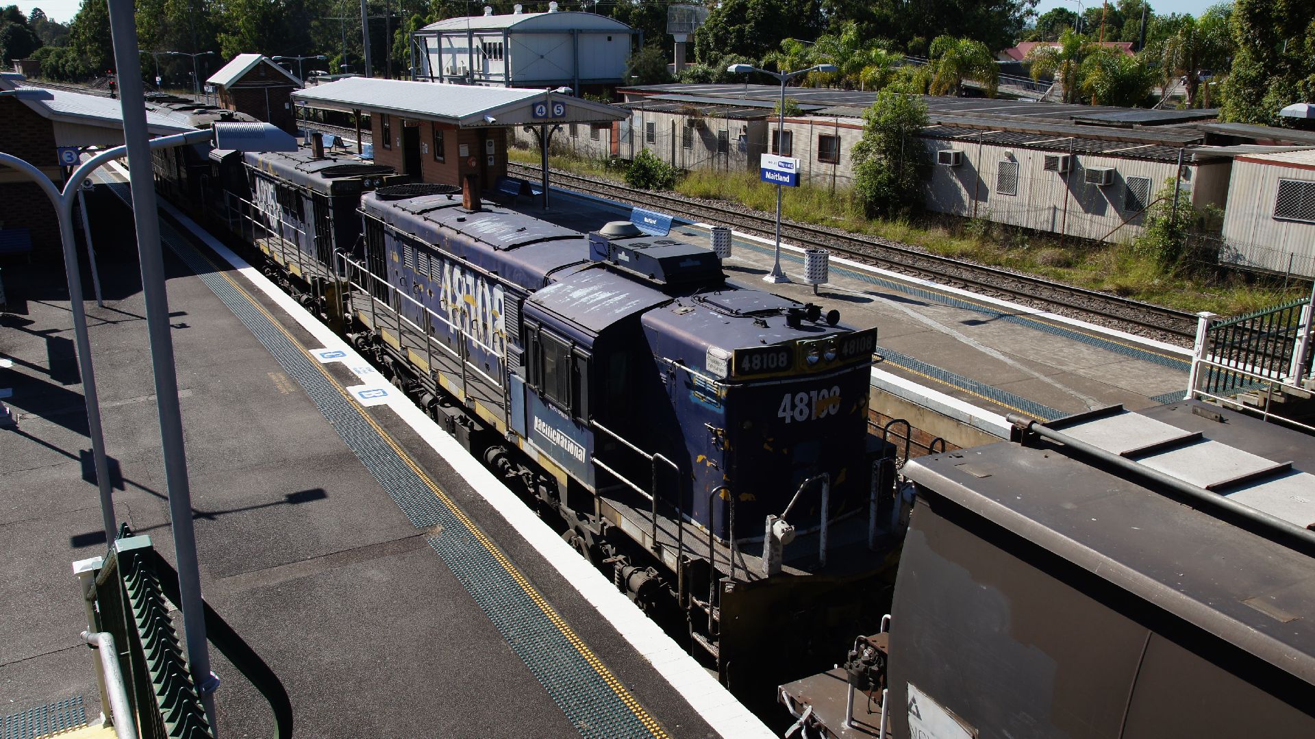
Day two
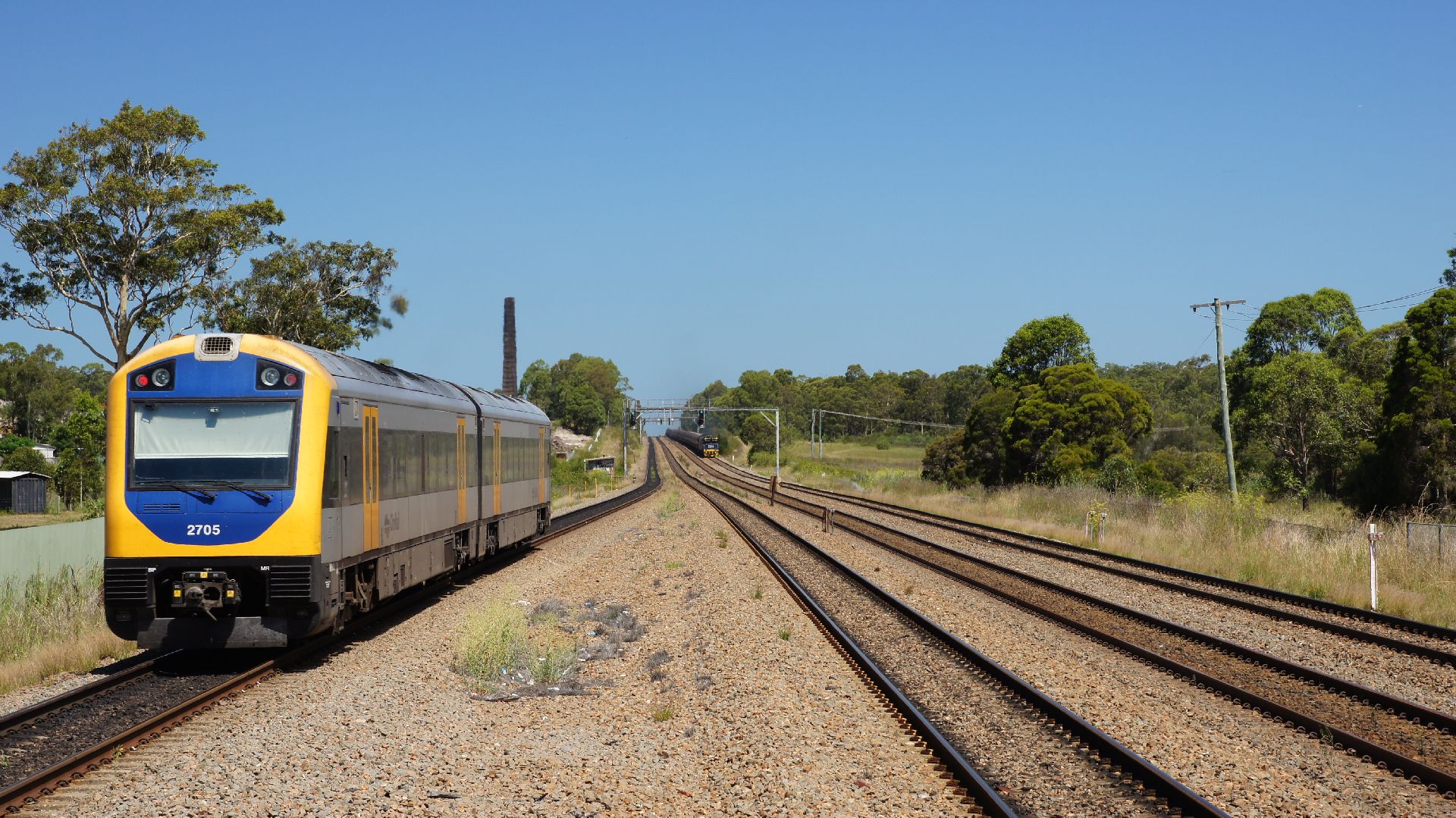
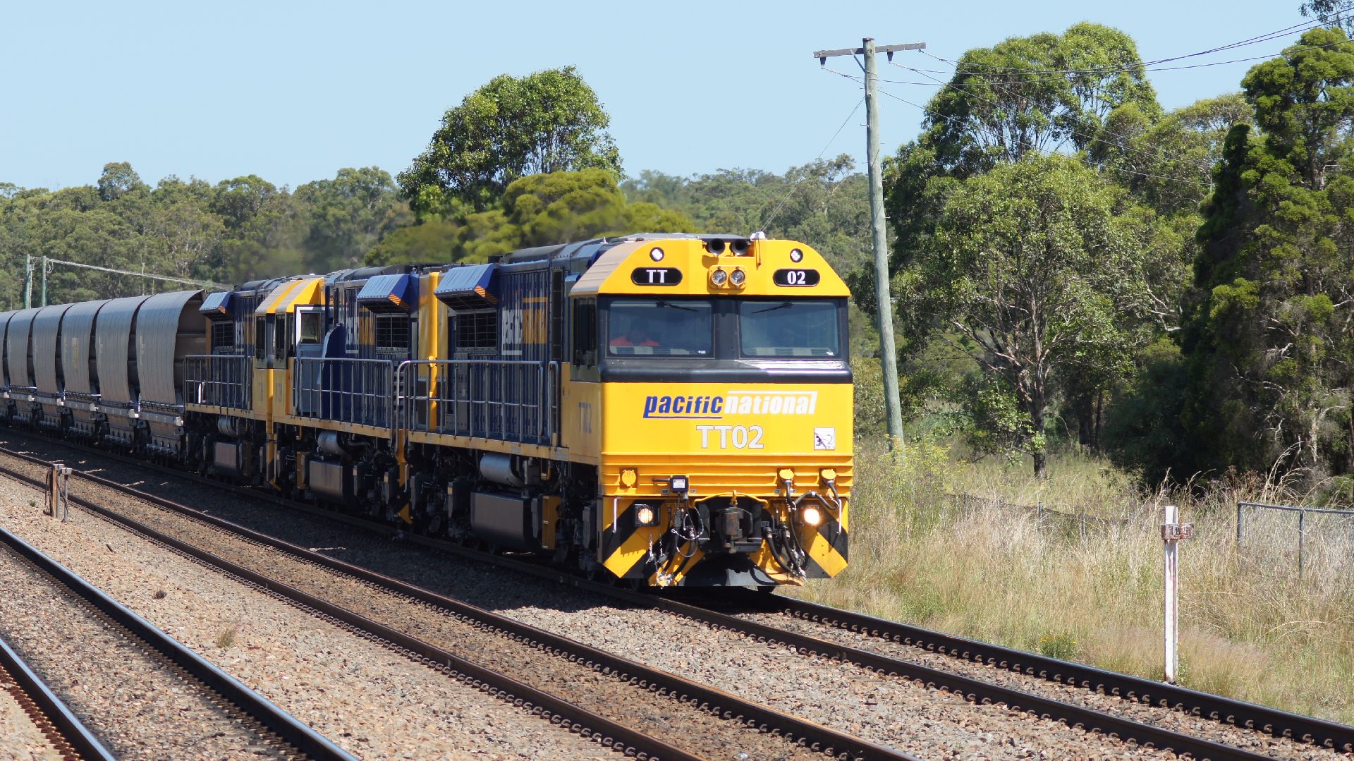
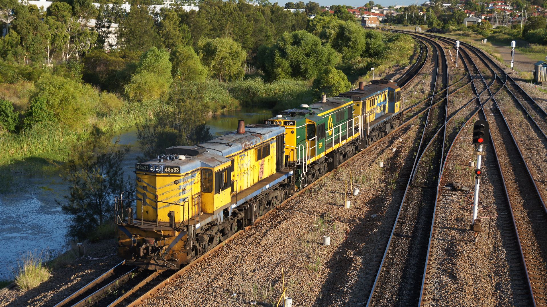
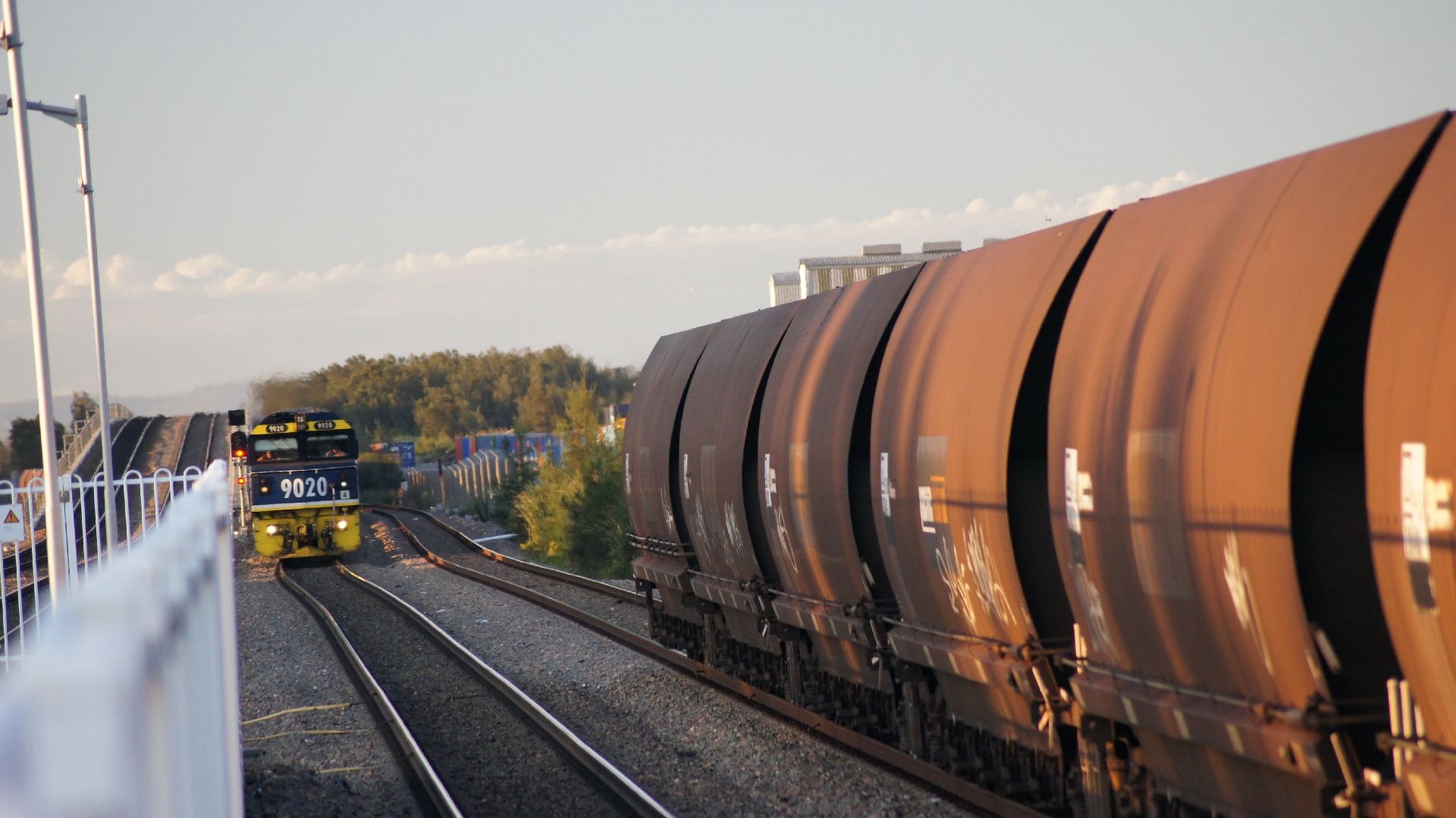
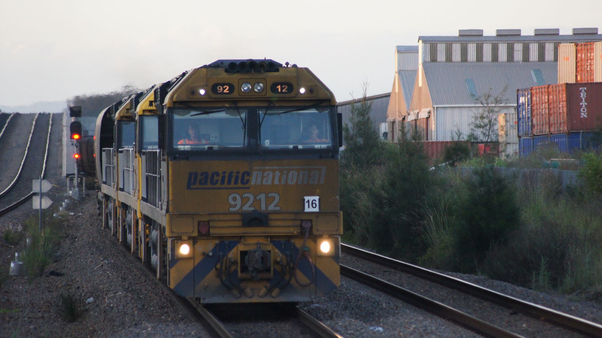
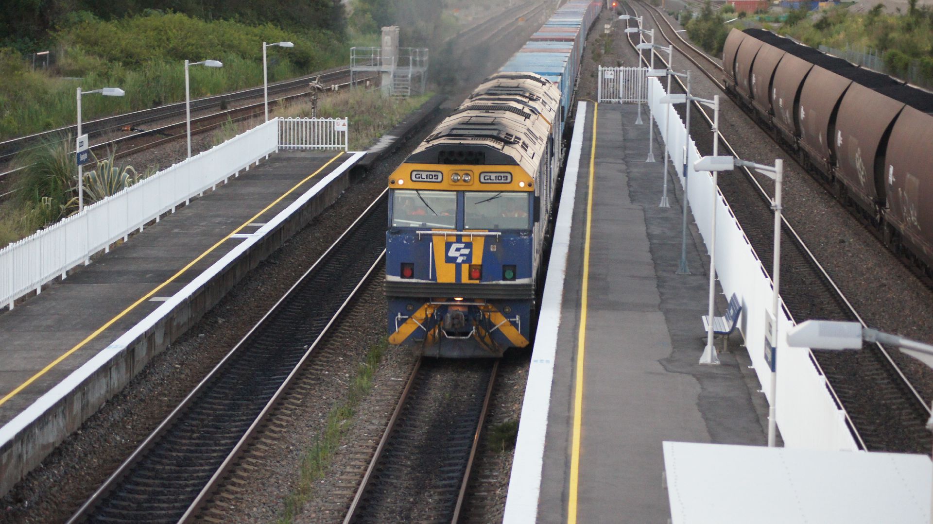
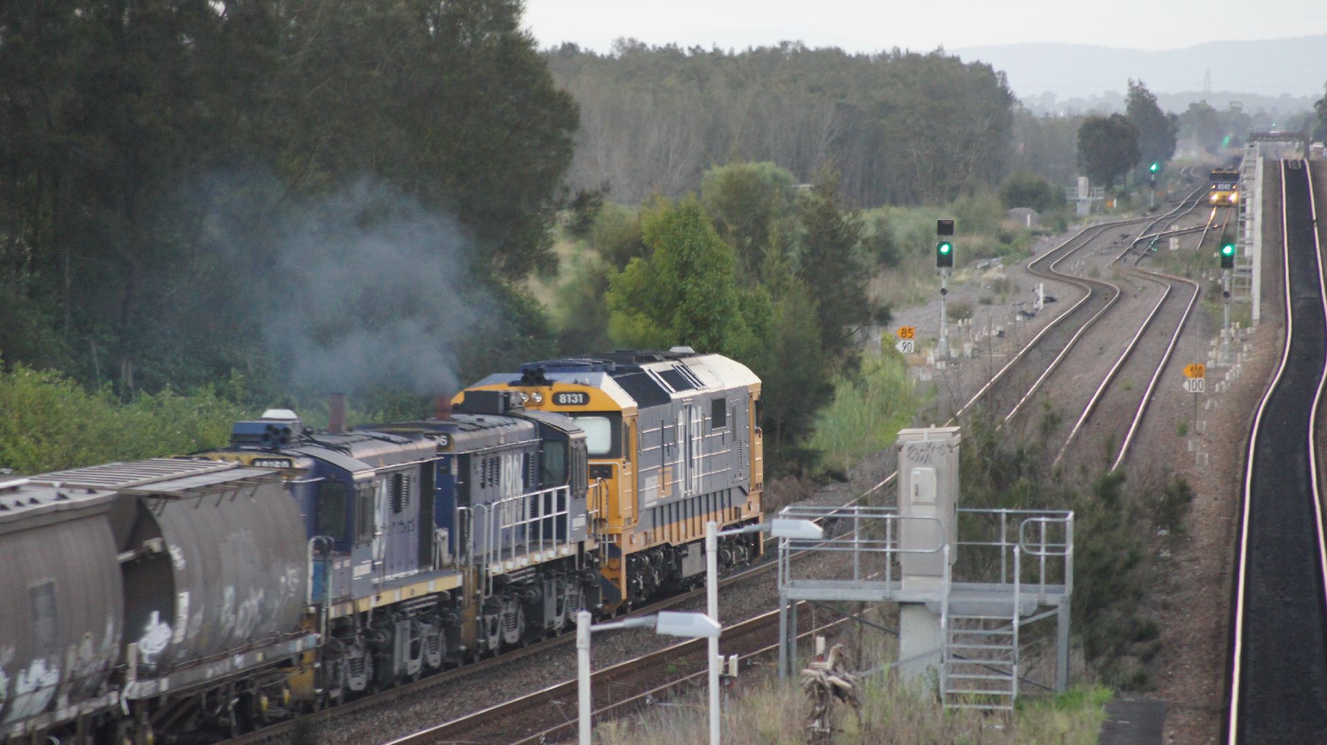
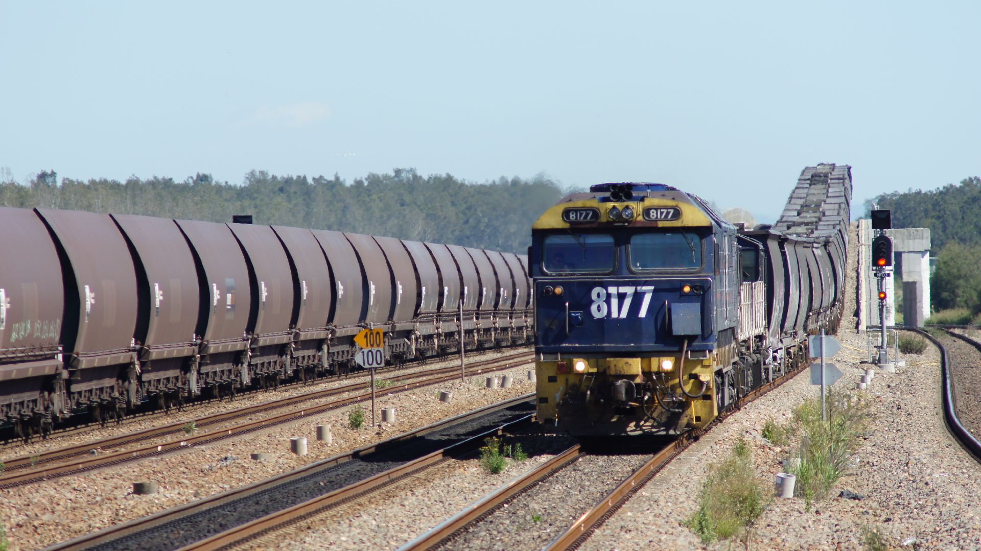
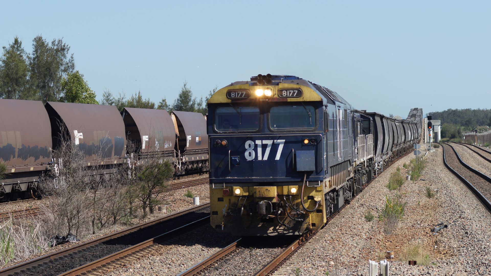
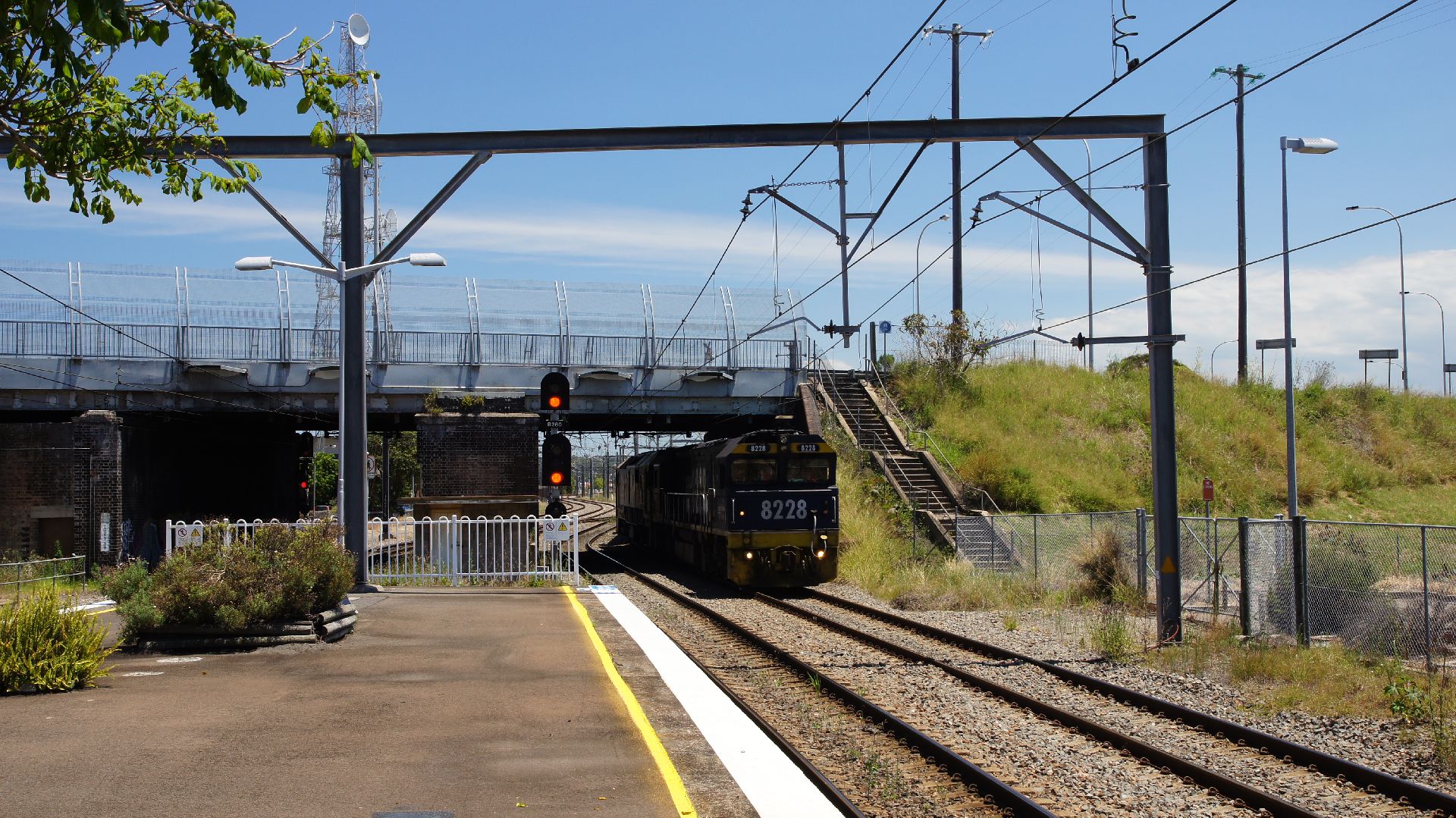
I was to catch the 6:65pm XPT from Maitland Station to Brisbane and therefore had the whole day to check out what was happening around the Hunter. I dumped my bags at Maitland Station and then proceeded to loiter at random points between Maitland and Newcastle. Fortunately, as soon as I'd sorted out my luggage, an 81 class + 2 48s rolled in with a grain consist. It turns out they were not going anywhere until the next DMU was through (thanks for that information from the drivers!) and therefore I took a few photos at Maitland Station and then waited for it at Sandgate.
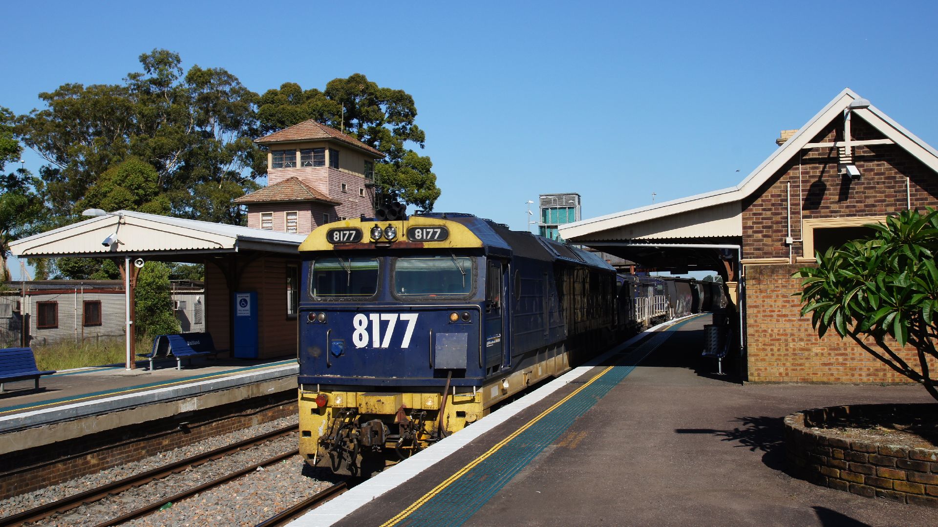
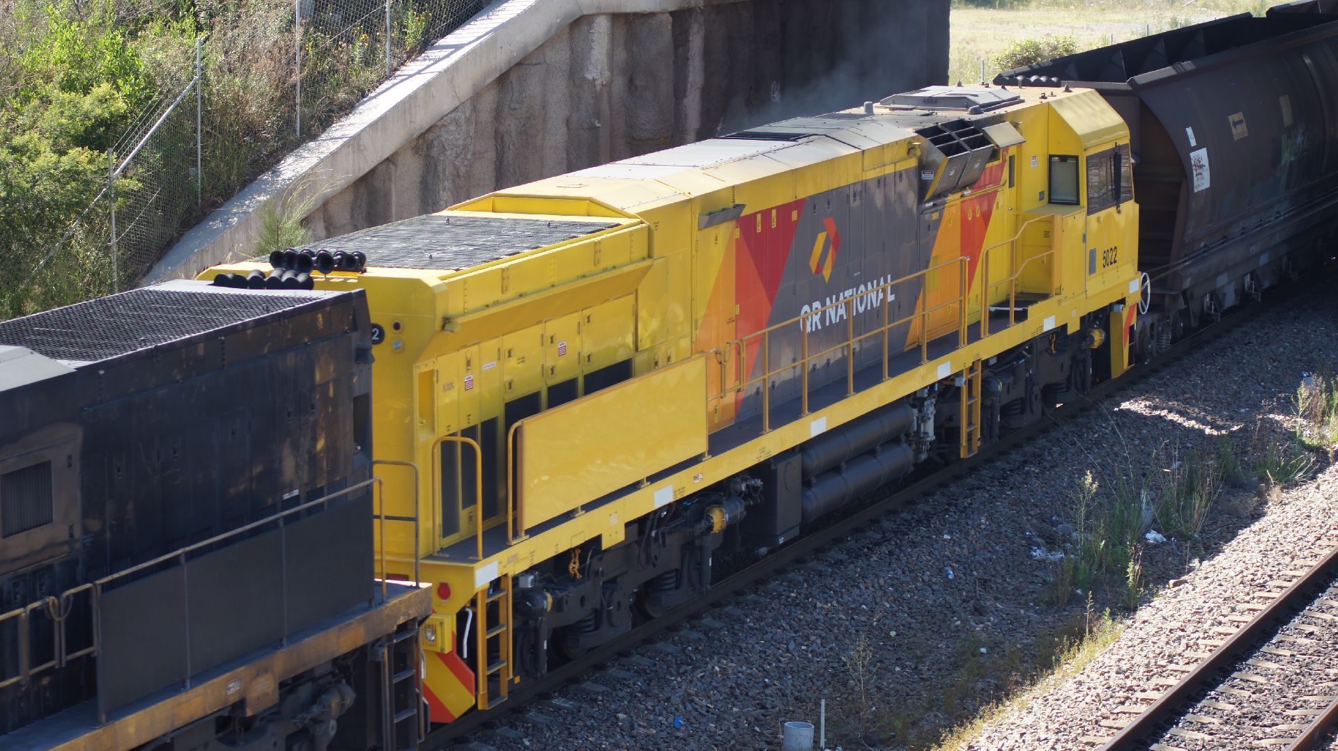
At Sandgate, the main line is elevated over the coal lines to Koogarang Island. I was told by the grain train drivers that they were to change onto the main line and proceed through to Broadmeadow yard. This meant that they would come over the hump... of course, I didn't make it to the platform end to get the 'perfect shot'... but it worked out OK anyway...
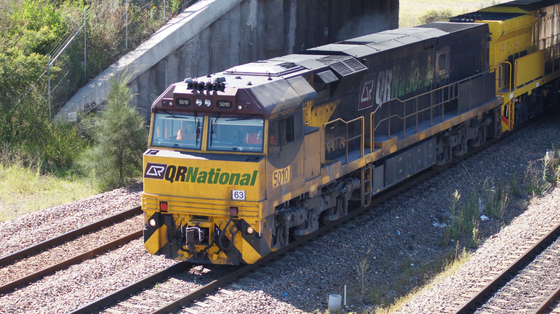
I loitered at Sandgate and was lucky to see QRs new liveried 50 class.
The rest of the afternoon...
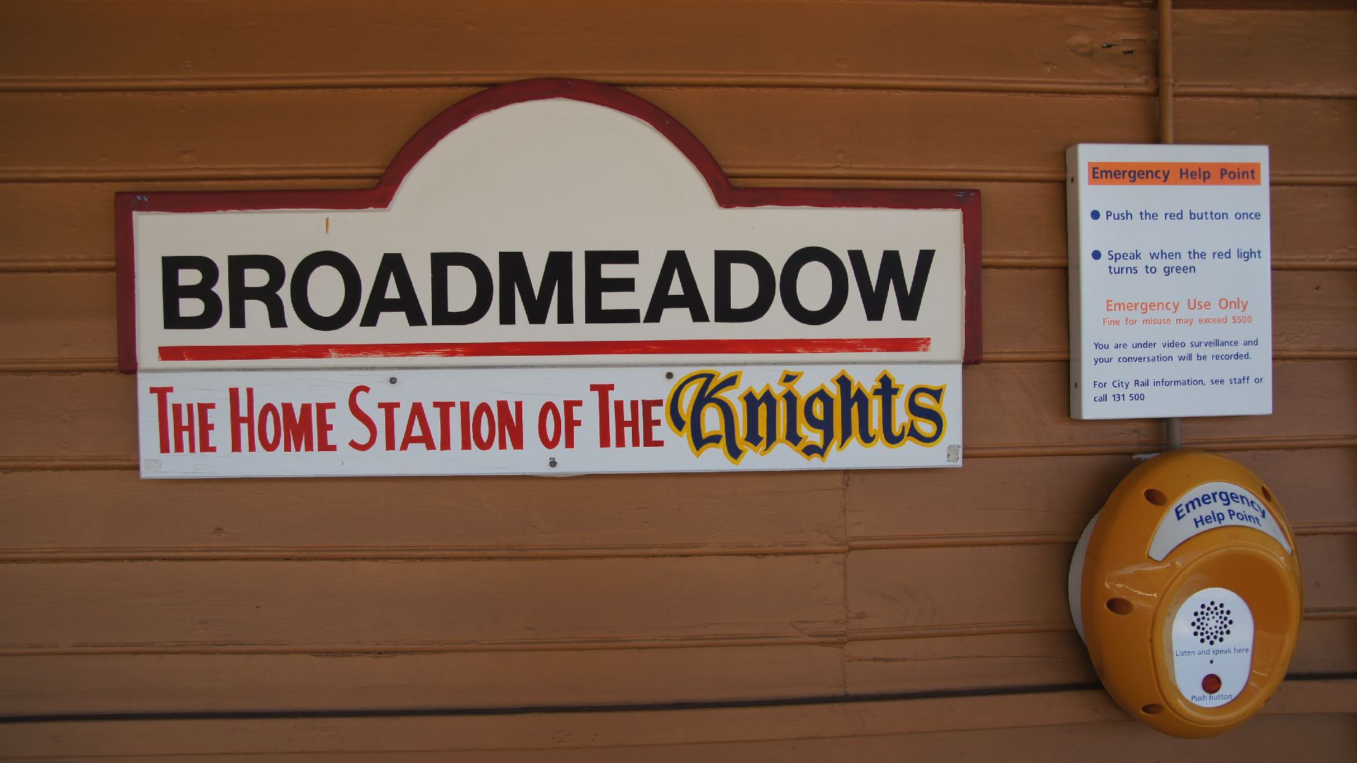
It was too hot by 11:00am to be hanging around in the sun and so I travelled on to Newcastle and swam at the main beach. Afterwards I ventured back to Broadmeadow Station to see if there was anything interesting going on. Broadmeadow is at the mouth of a maintenance/storage yard for locomotives and wagons. Unfortunately I only got to see a coal train passing through.
Back to Warabrook Station
I had been on to a good thing the day before, and so I though I would return to see what else was moving around.
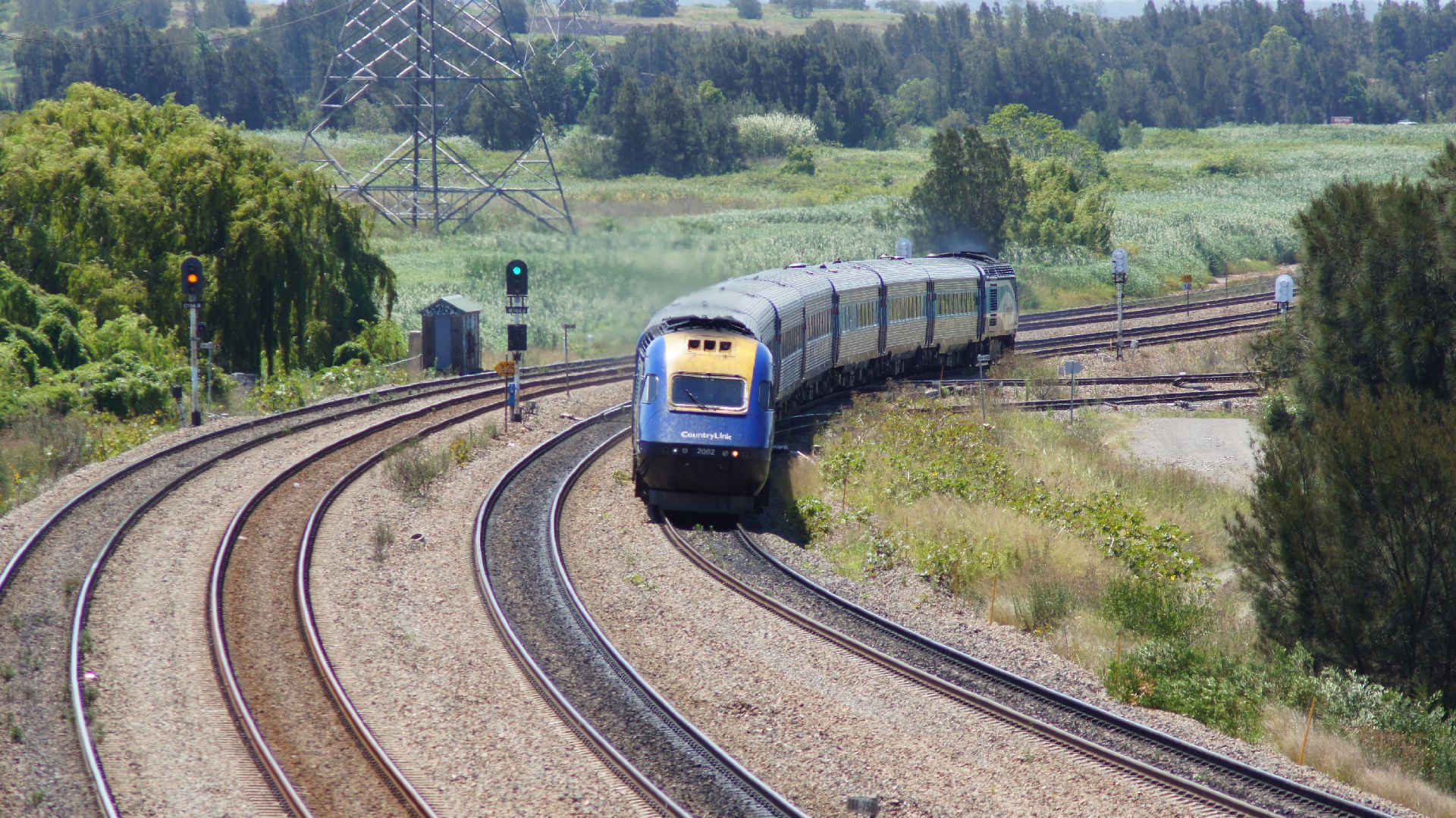
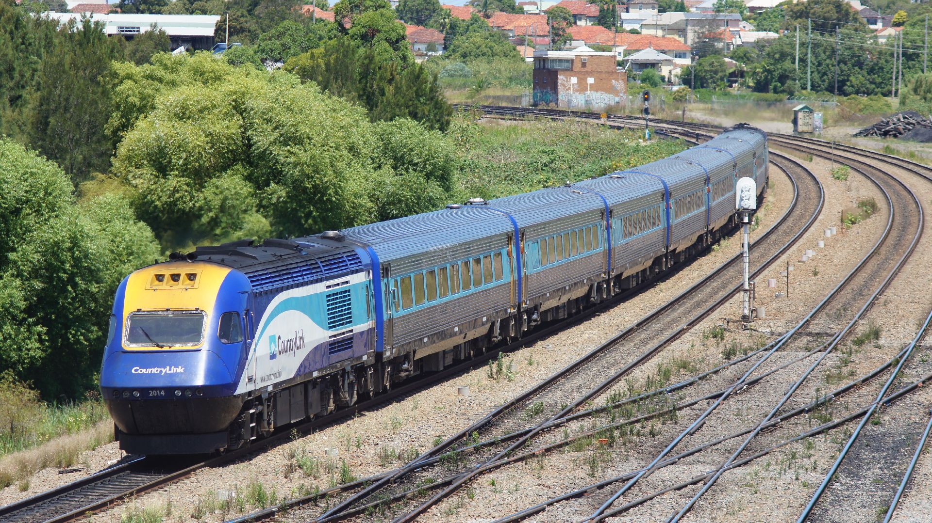
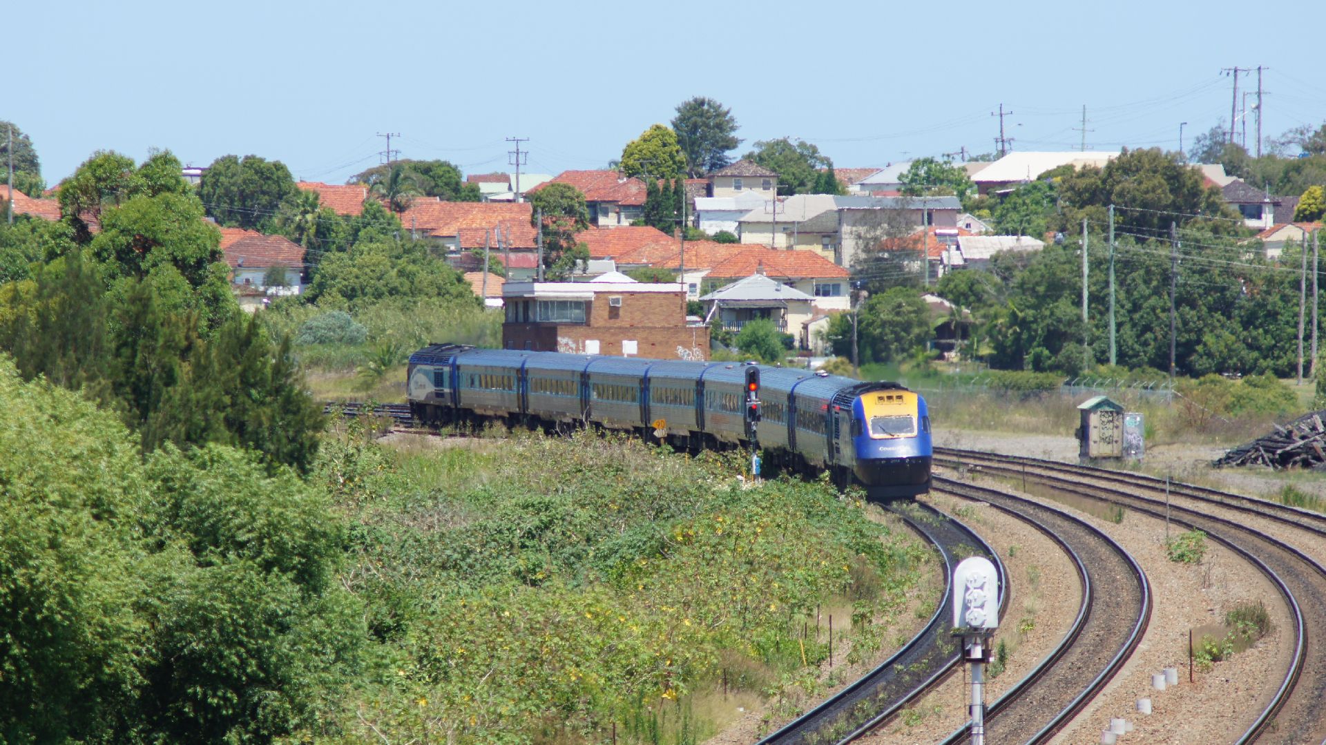
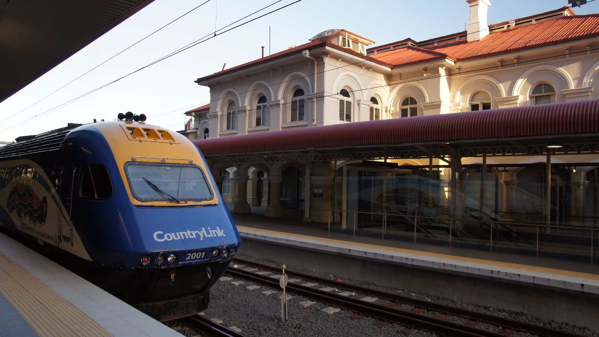
Overnight on the XPT
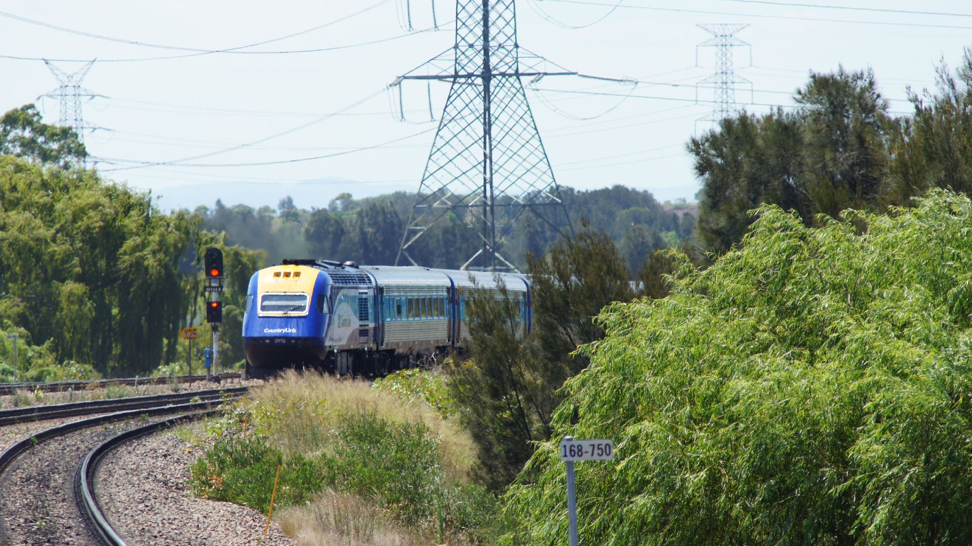
I'd done this once before, back in 2000 or so, and I can only imagine that I'd forgotten how difficult it was to sleep upright. We ran on-time all the way, but the track wasn't as smooth as it could've been.
Meanwhile, the view as the sun was setting north of Maitland was beautiful. Rolling green pastures and lots of stock roaming around or running from our train. Unfortunately, the sun set pretty quickly and the reflective tint on the outside of the windows meant that there was next to zero visibility.
Lights were out at 10:00pm and most people tried to sleep (some with very loud music in their earphones.) Sleeping wasn't too easy though, as there were stations all throughout the night and people were getting on and off the train, dragging their luggage and making enough noise to wake all the light sleepers up. Even better was the fact that the guy next to me wasn't meant to be there, so at 11pm we all had to shuffle around when the actual passenger arrived.
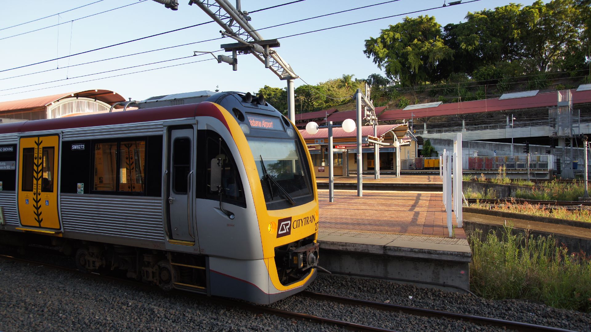
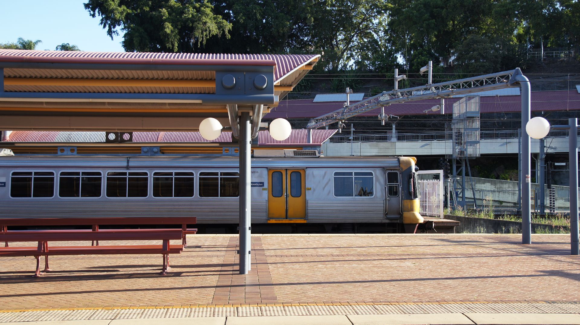
After a random amount of sleep, then sun started rising at 5:30am and the view from the train was undeniably suburban Brisbane. A lot of the houses we passed backed on to the railway line and didn't care much for fences. We finally arrived at Roma Street Station and then I transferred to the Gold Coast Line to Nerang.
Final words...
Until Australia cares for passenger trains... CountryLink will be the only option for east coast travel. The line has been primarily built for freight trains and therefore there is no regard for speed or smooth travel. They have done a lot of improvement work over the years, but again, population and demand is lacking to make any more of it.
I would recommend this trip be done during daylight as opposed to overnight. The view is spectactular and having had the sun up during the entire route would have been great. The only other way to do it would be via a sleeper compartment, but the cost will be quite prohibitive for the foreseeable future.
Eizan Dentetsu (Eizan Electric Railway)
The Eizan Dentetsu (Official Site [Japanese Only]), known as Eiden for short (a combination of 'Eizan' and 'Dentetsu'), is a private railway in North-East Kyoto, Japan. This railway was originally owned by Keifuku Railways, but is now a wholly-owned subsidary of Keihan Railways. Prior to the purchase, Keihan had extended their Main Line to Demachiyanagi Station where the Eizan Railway starts to increase rider-ship in the Eizan Railway.
Location
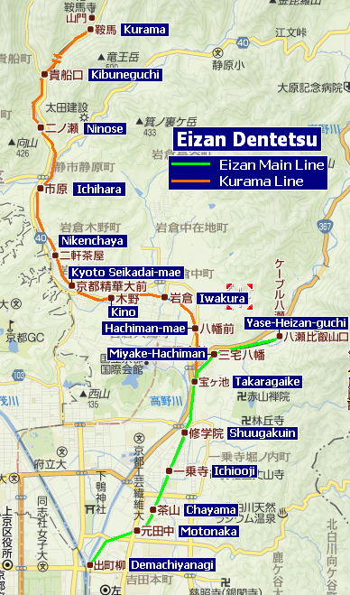
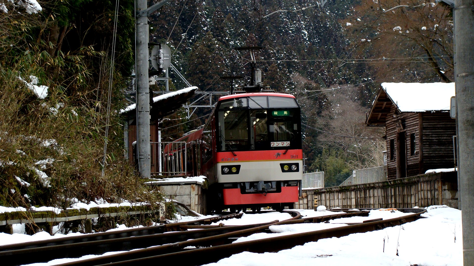
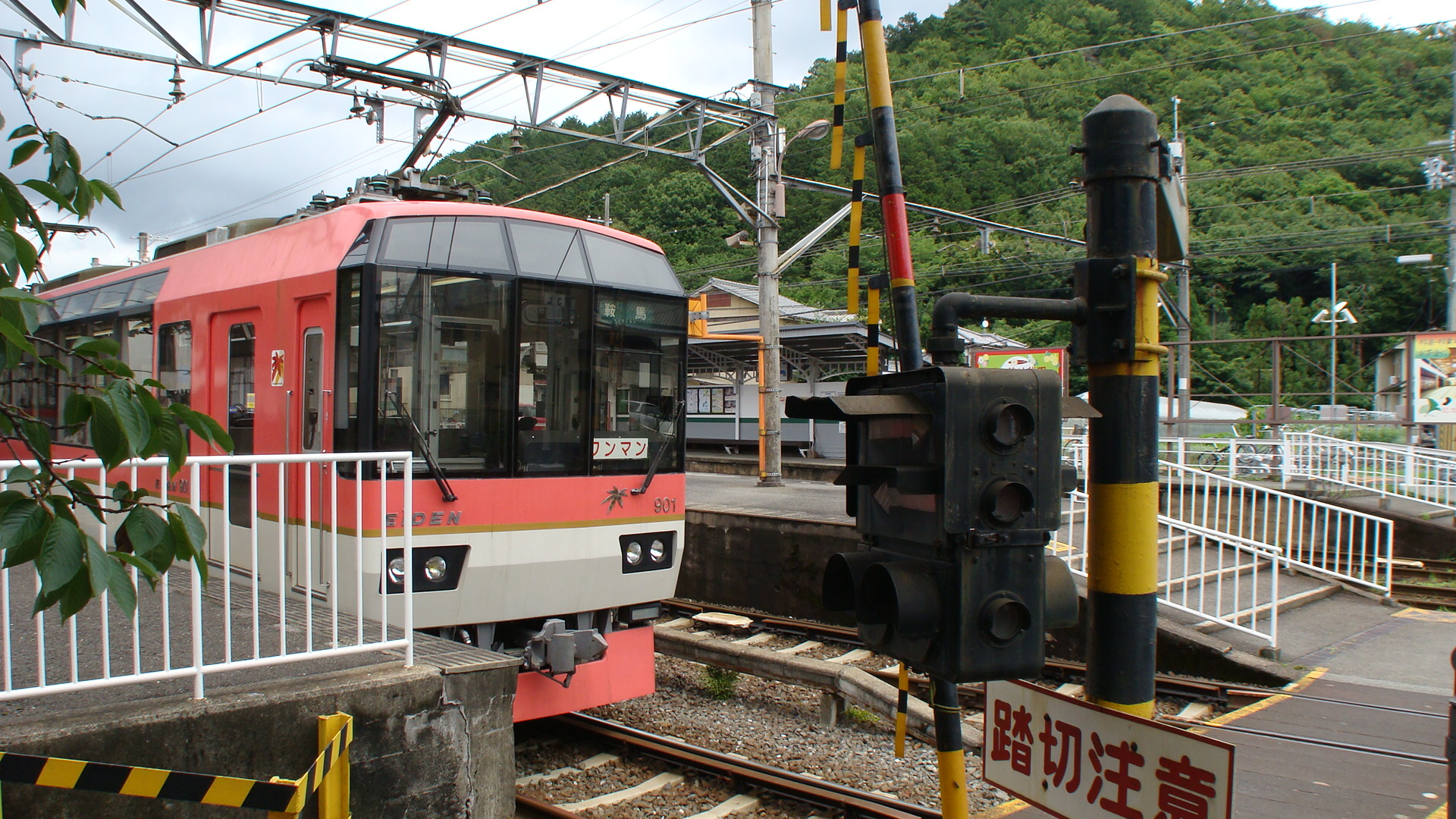
The Eizan Electric Railway originally only had one main line from Demachiyanagi Station in the north east to Yase-Heizan-guchi, further north-east. This line was opened in 1925 and provided a gateway to Mount Hiei, a popular tourist destination in Kyoto. The branch to Kurama was opened in 1929 and has proved popular ever since. Both lines terminate at transfer stations where passengers continue travel on cable cars.
From 1978, Demachiyanagi Station was cut off from other forms of connecting transport when the Kyoto City Streetcars stopped running. Fortunately, in 1989 the opening of the Keihan Oto Line through to Demachiyanagi re-connected the Eiden to the wider network and made it easily accessible once more. The Eiden network had seen lower ridership in between 1978 and 1989, but it soon became popular once more.
Rolling Stock
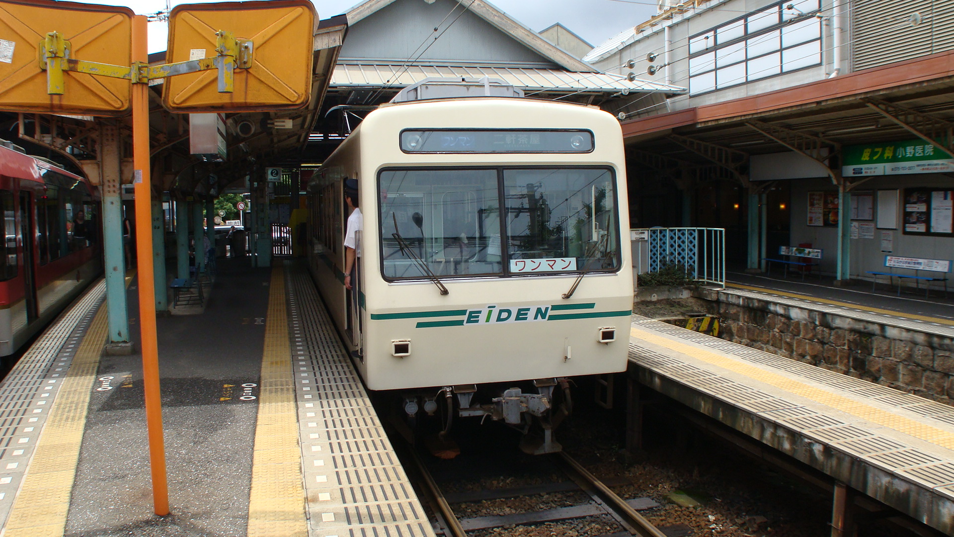
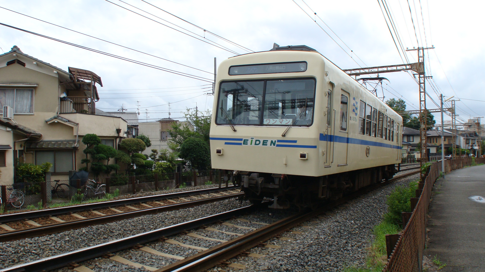
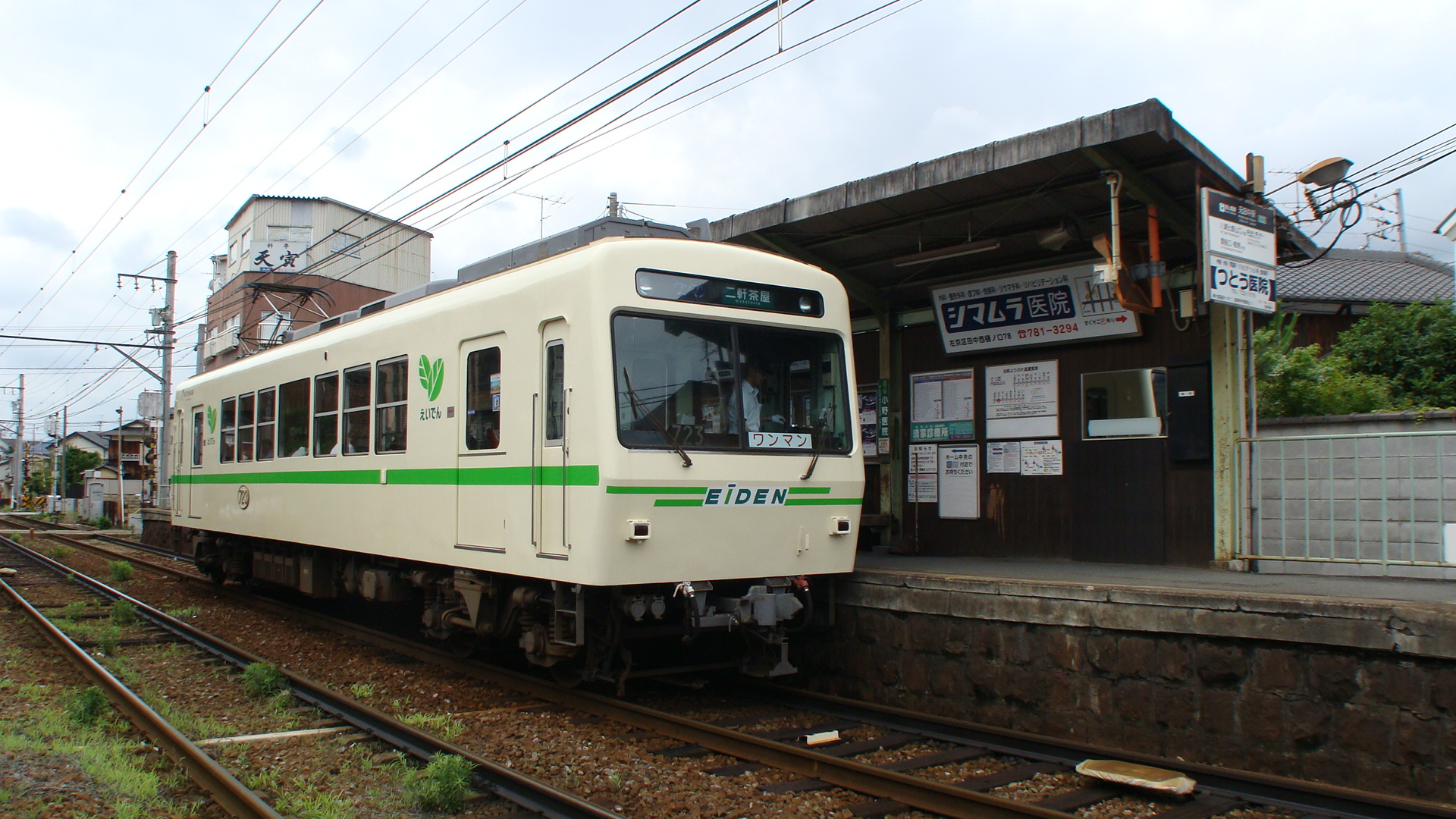
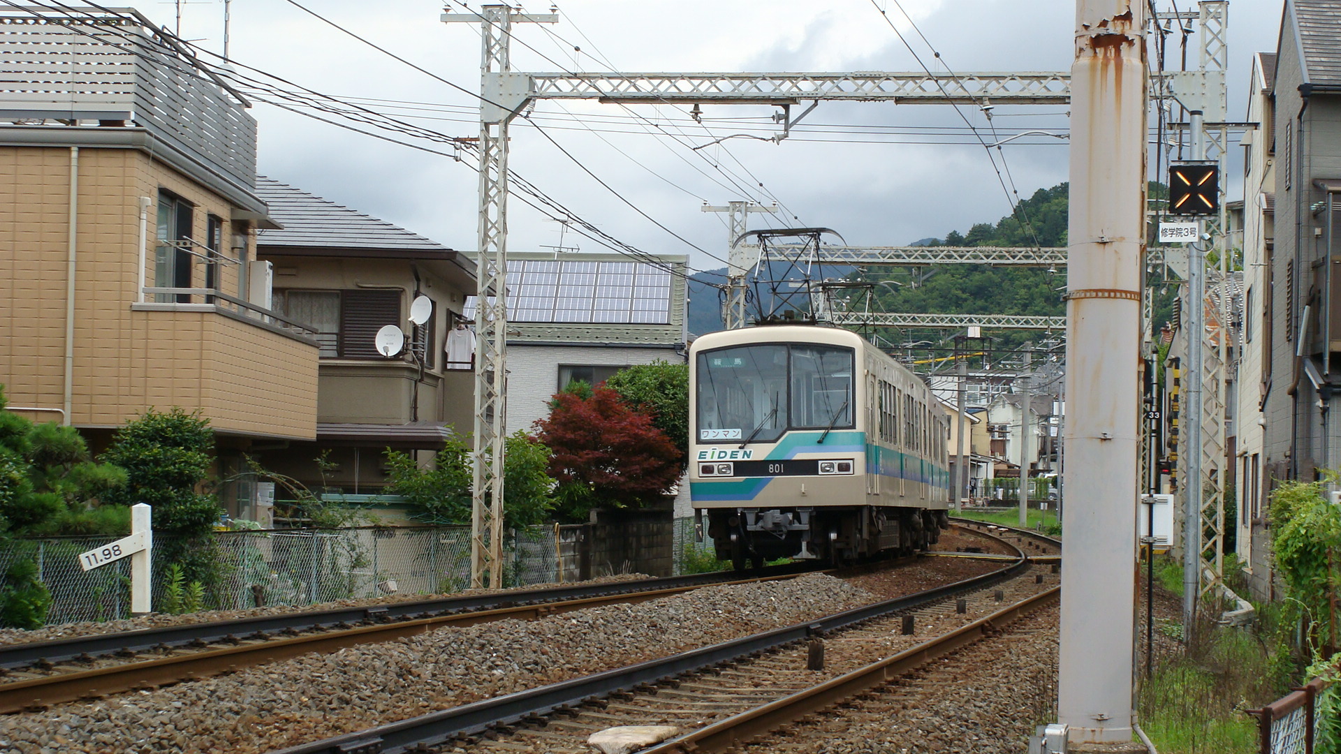
The Eiden's rolling stock inventory consists entirely of EMUs running at 600VDC. The Deo 700 Series is a single-car EMU which usually runs along the Main Line.
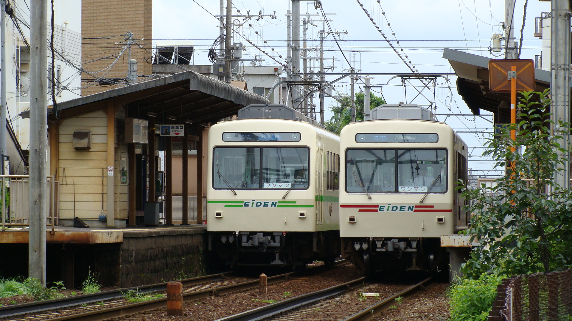
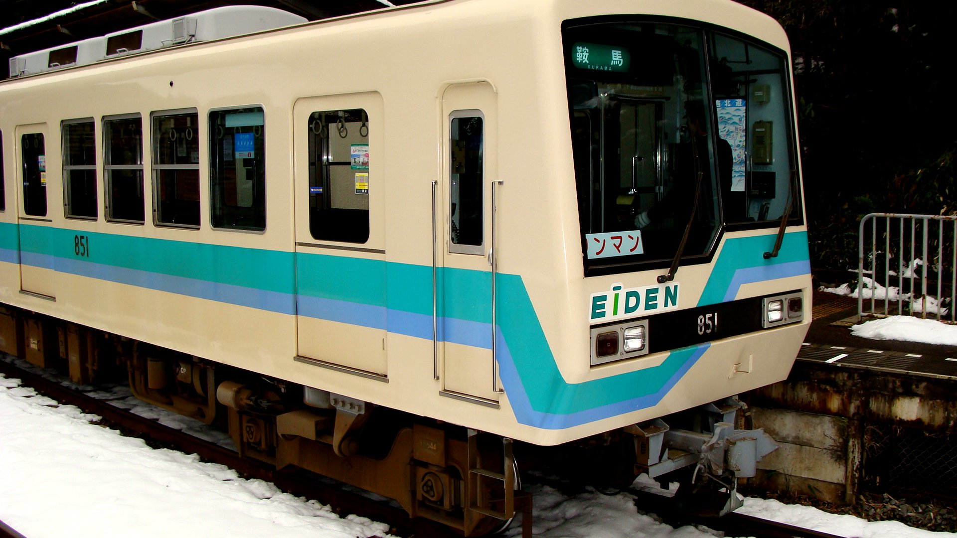
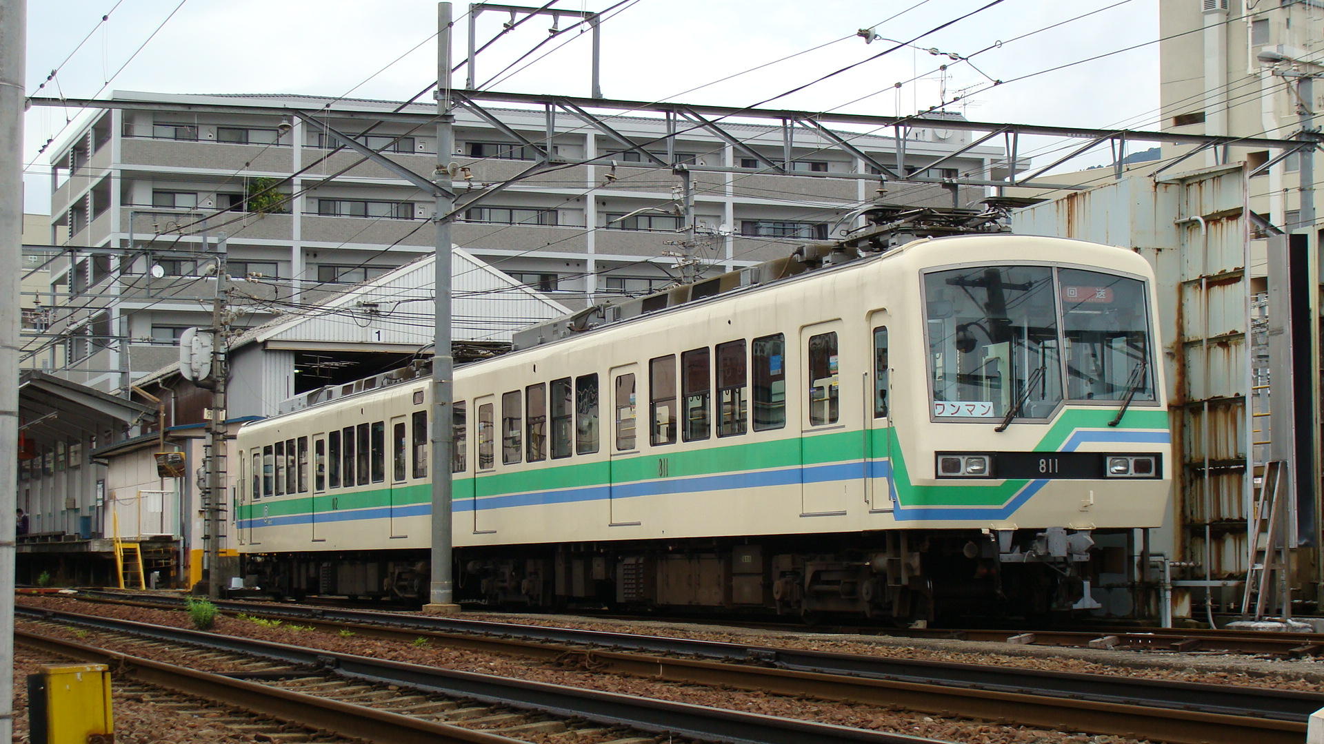
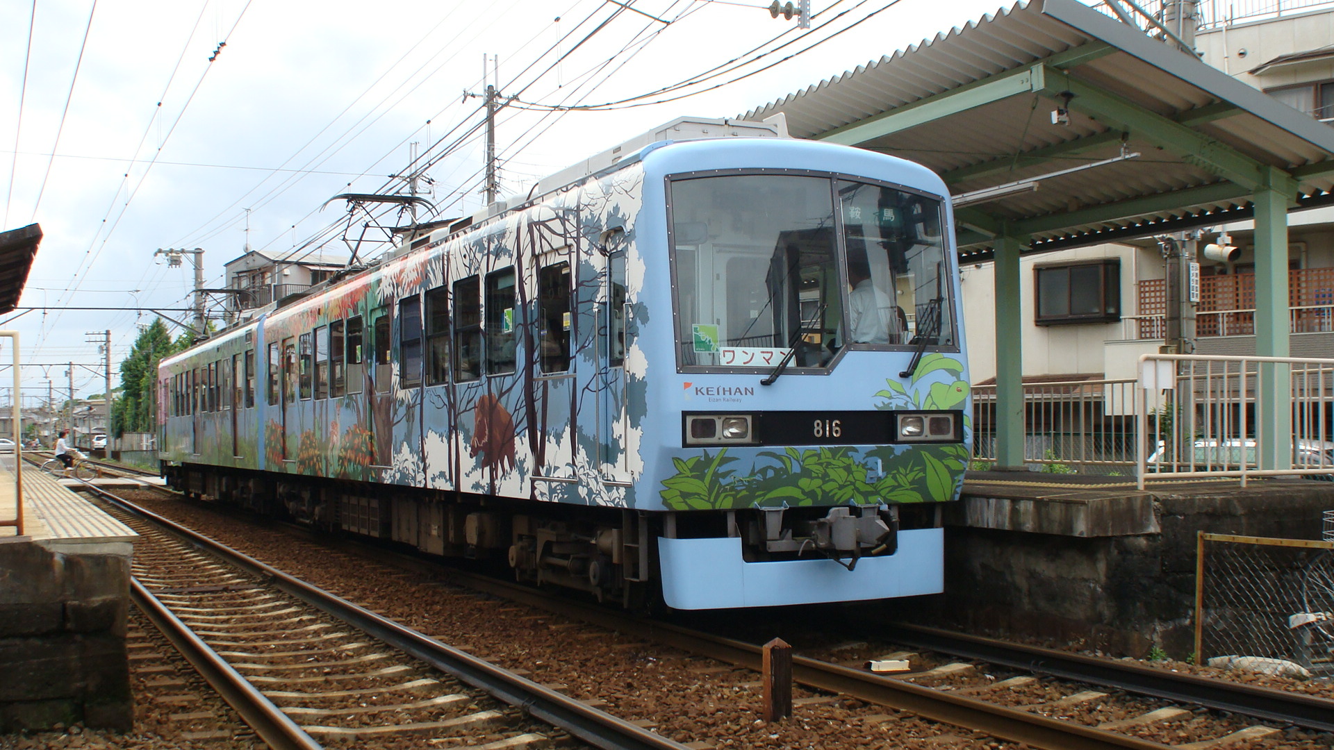
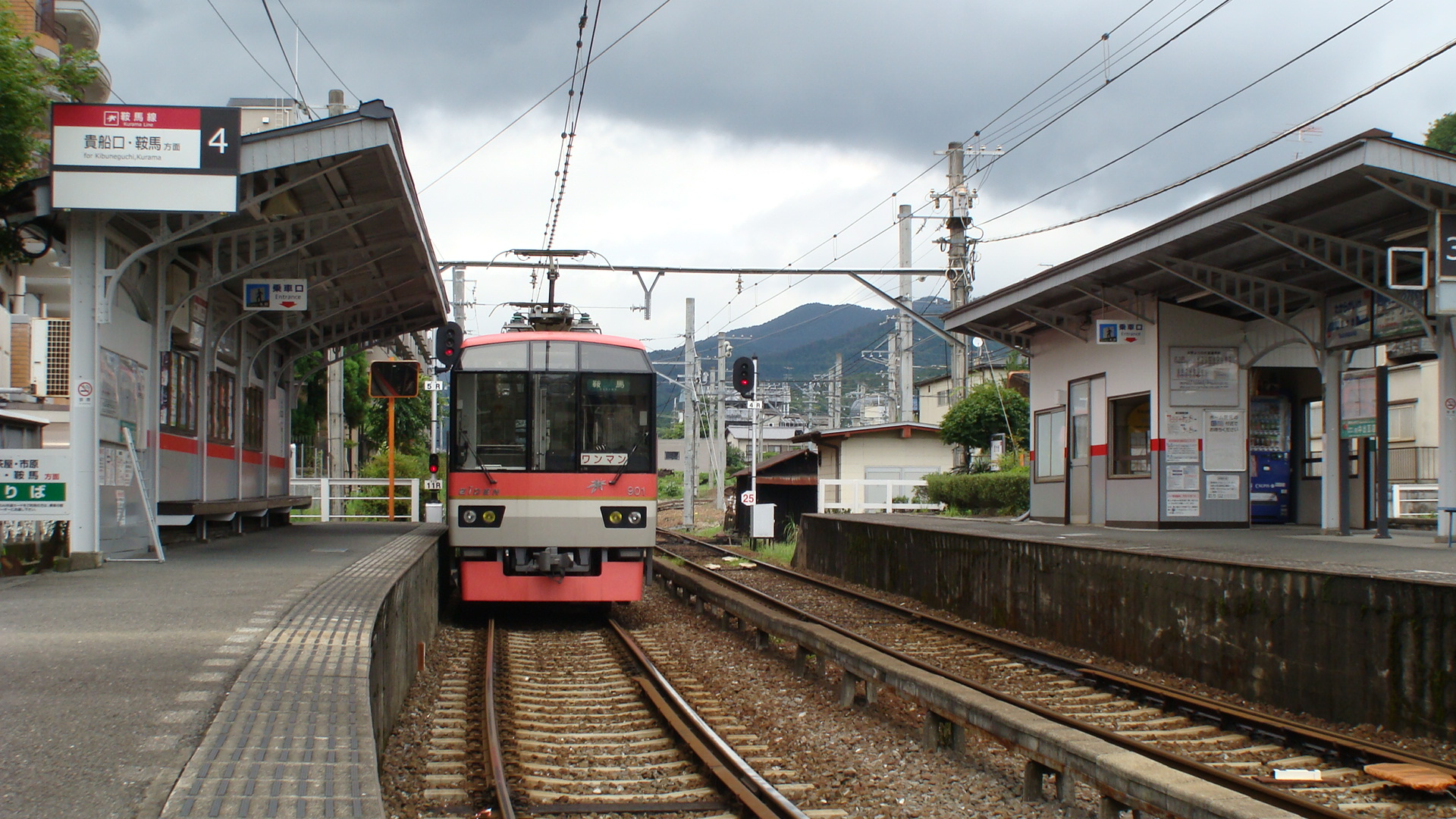
The Deo 800 series is a 2-car EMU which usually runs up to Kurama.
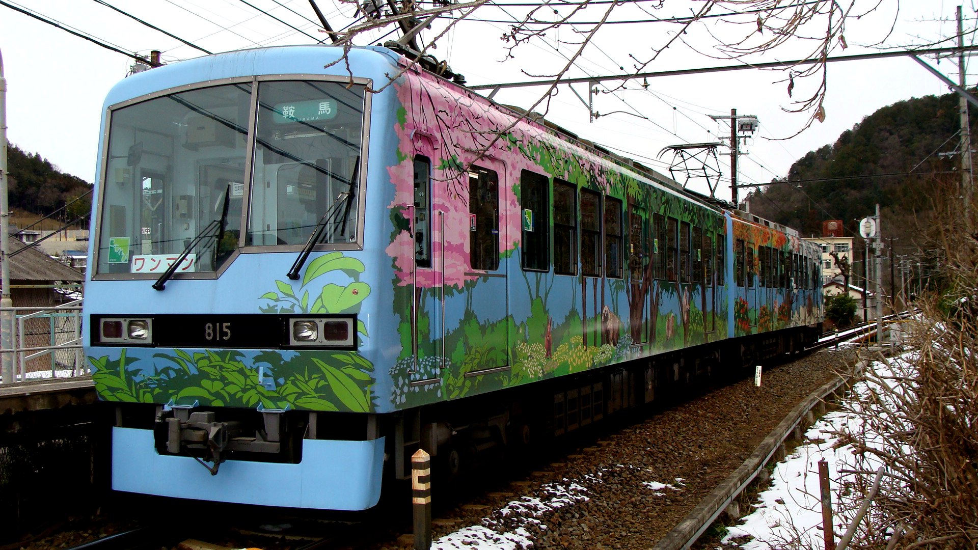
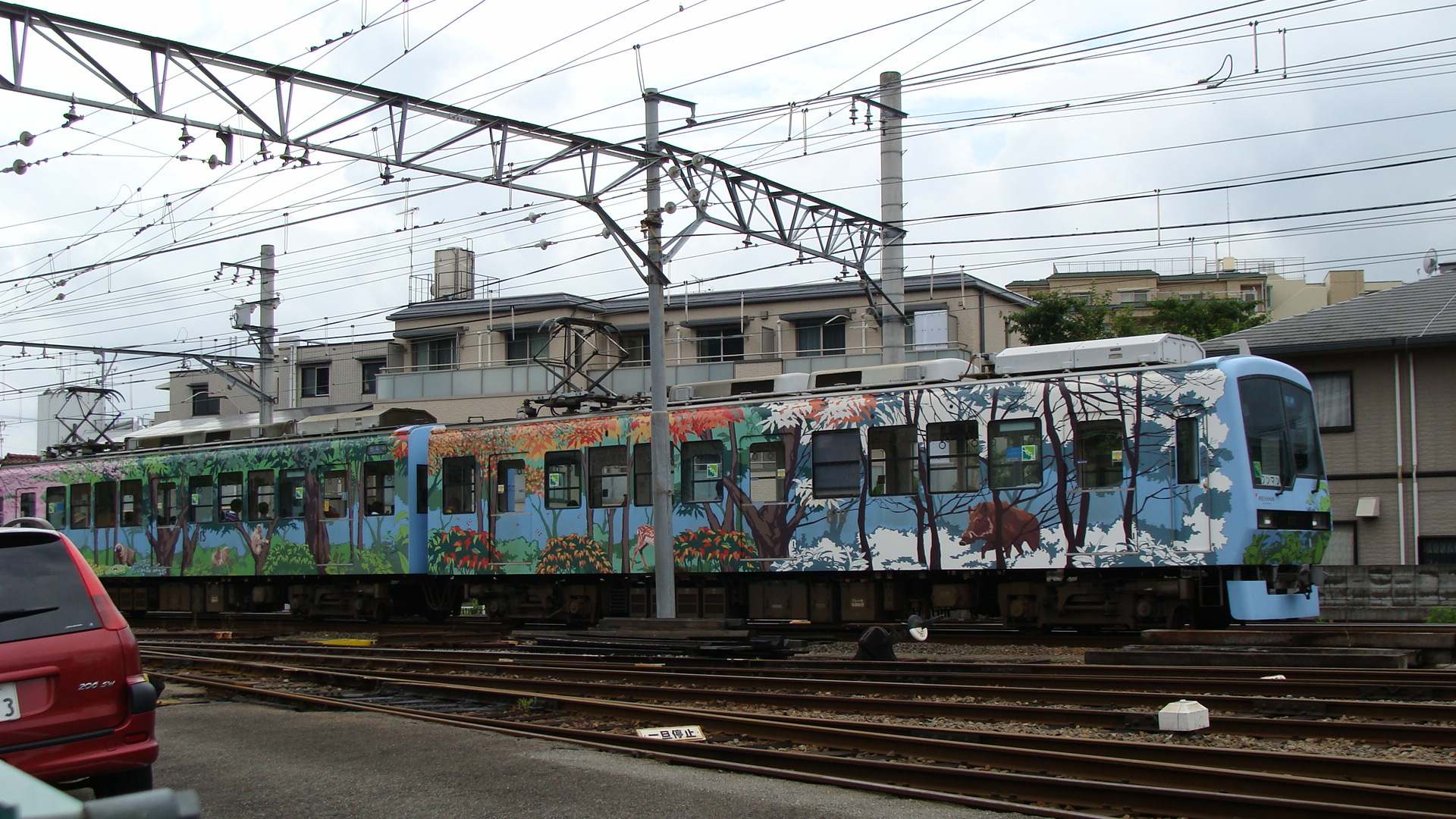
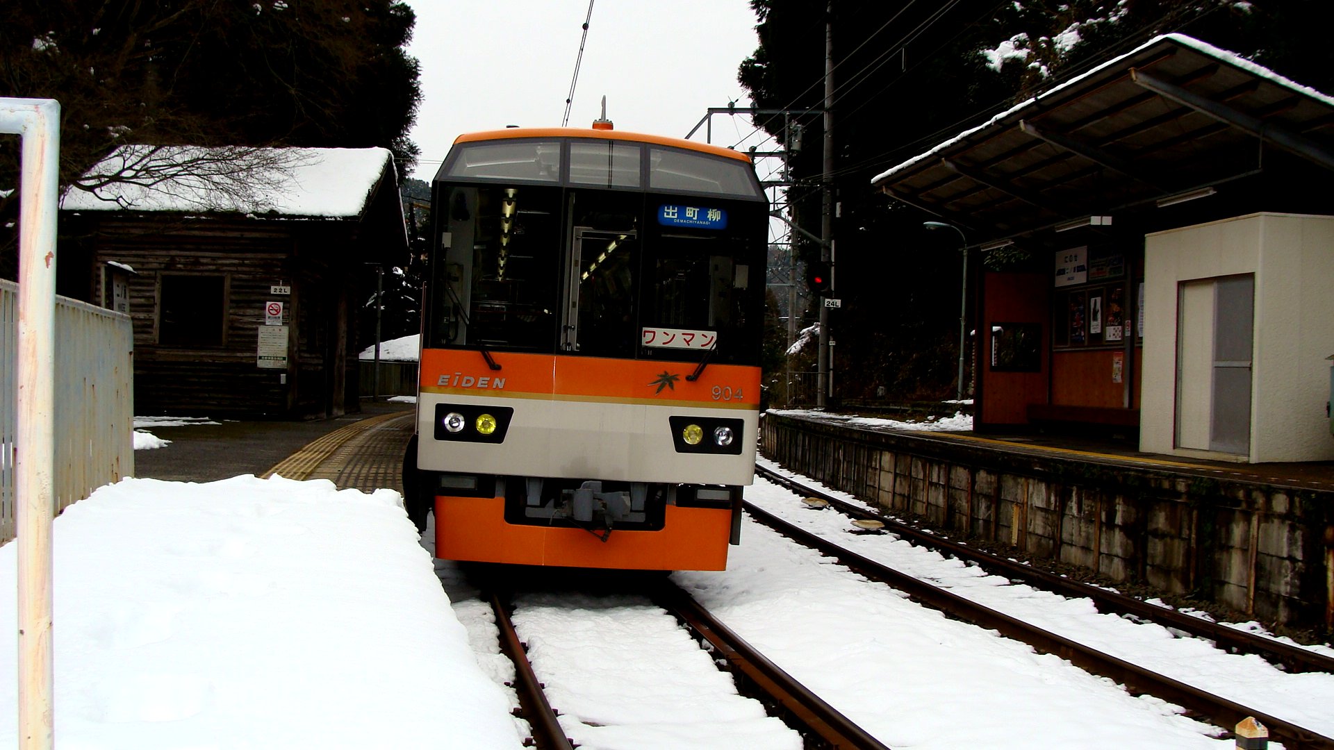
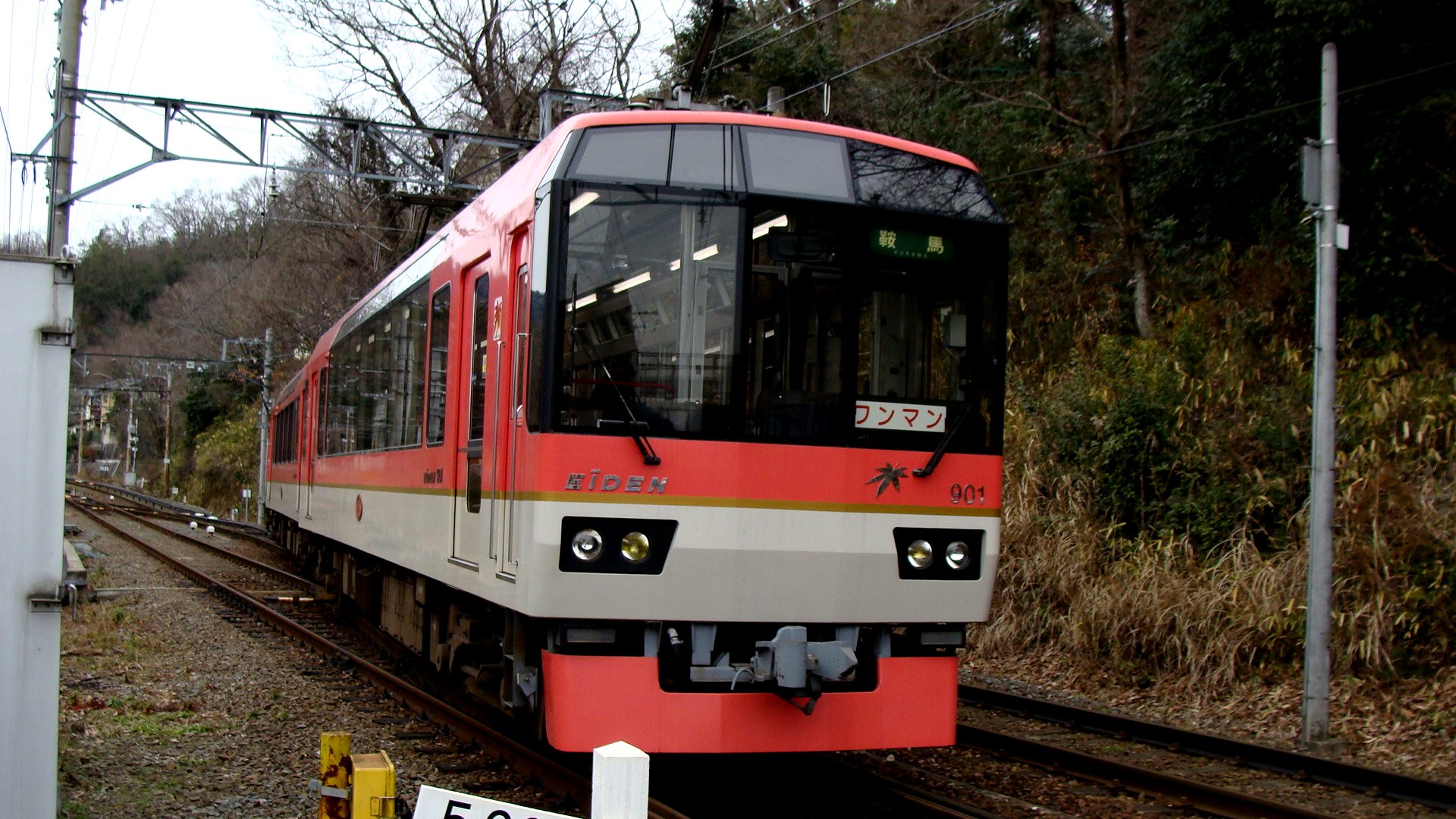
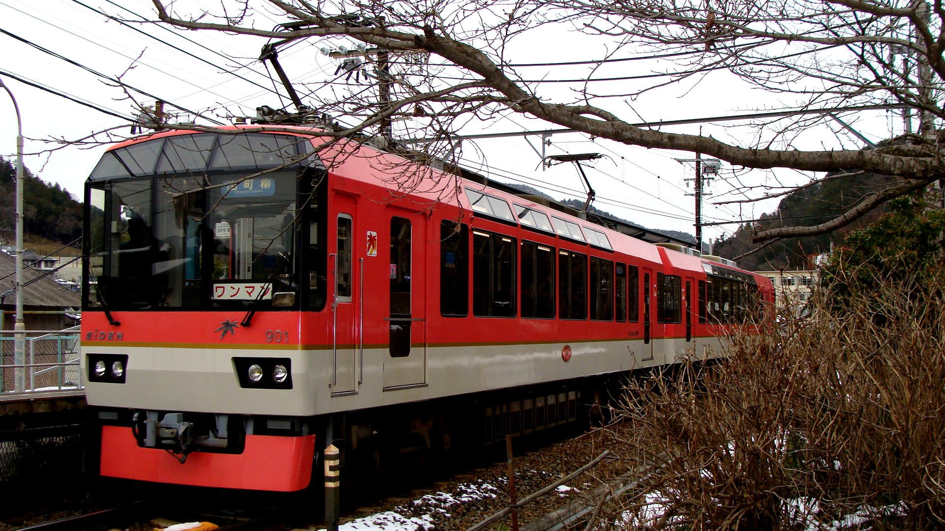
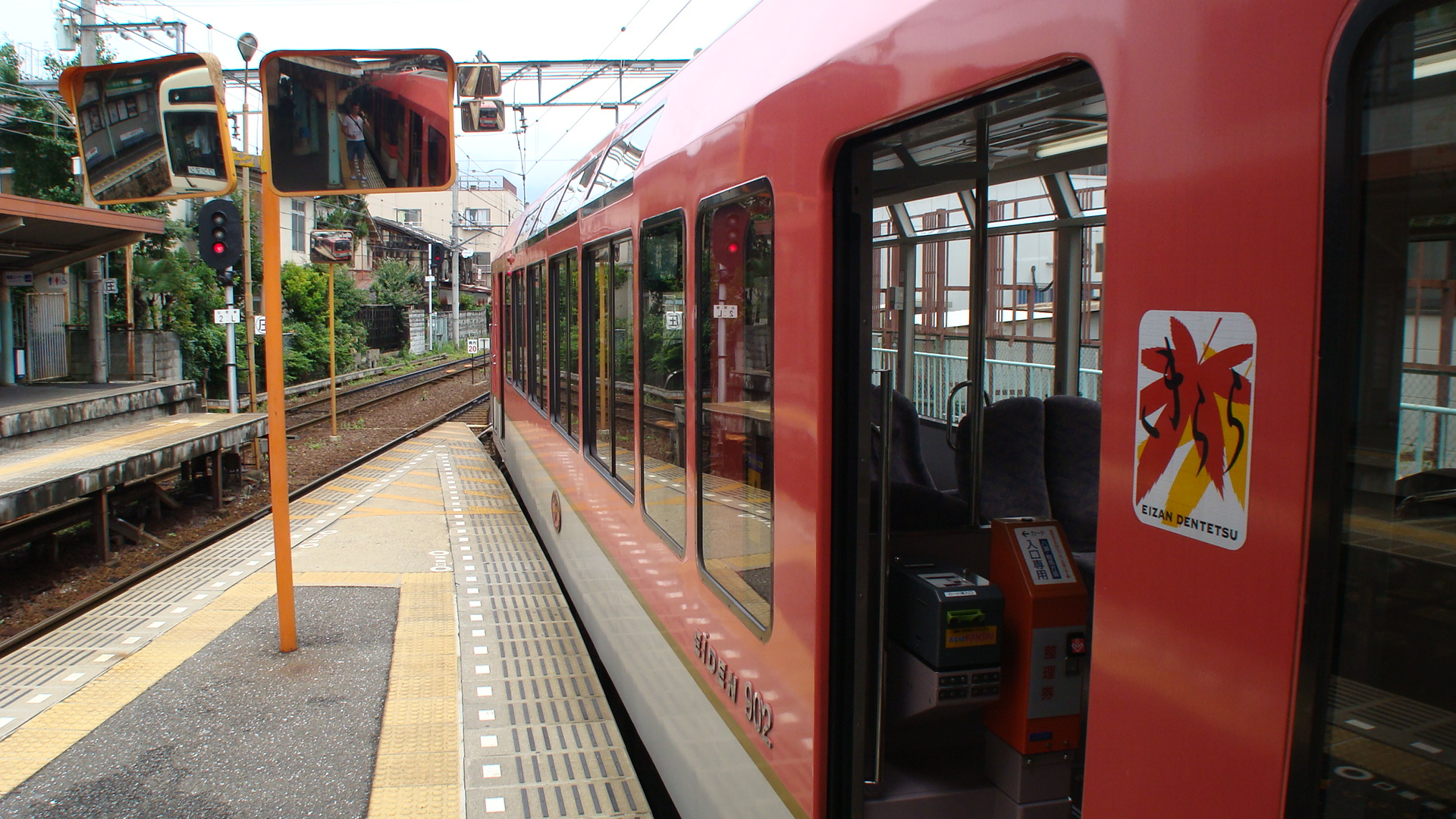
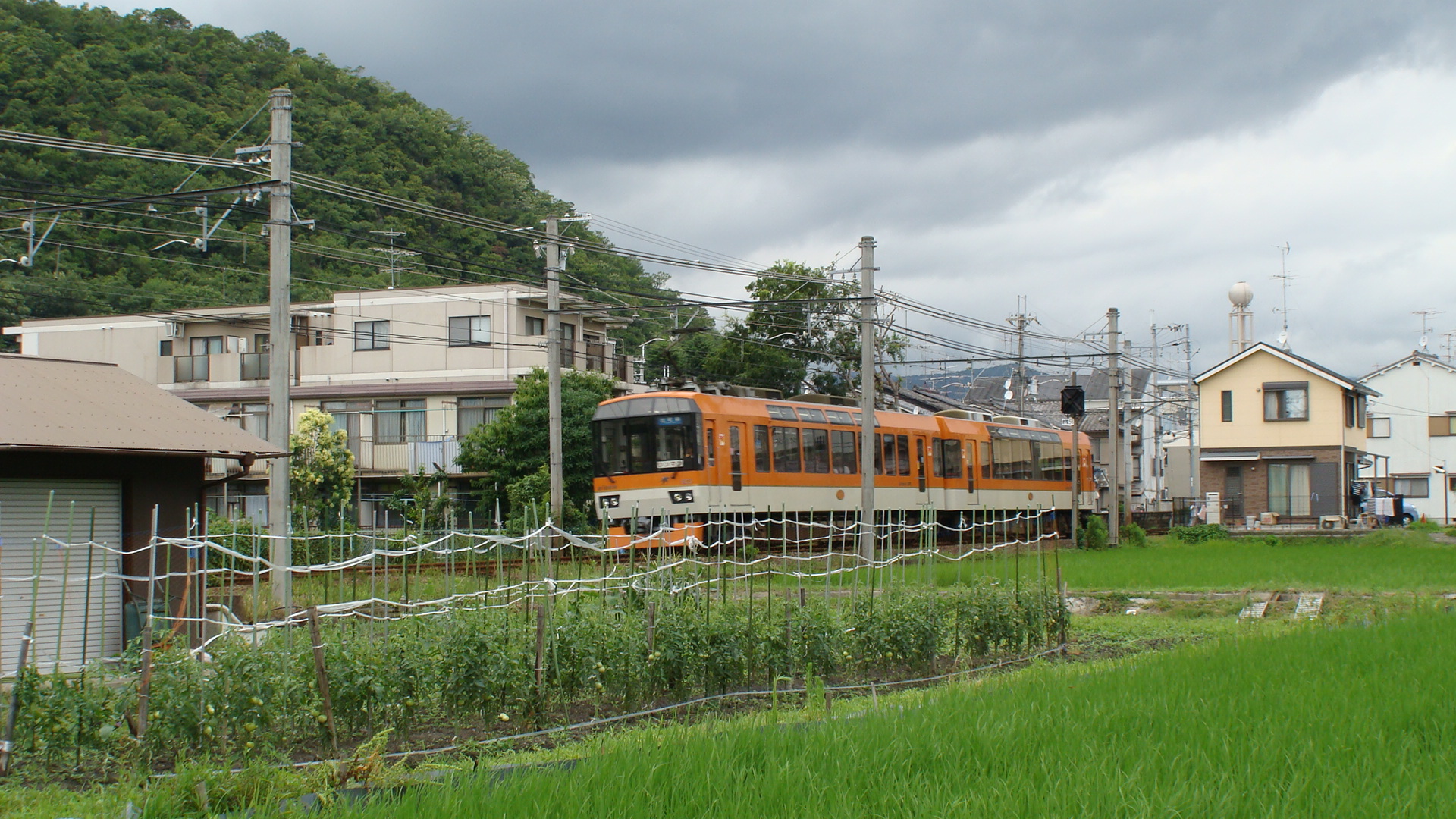
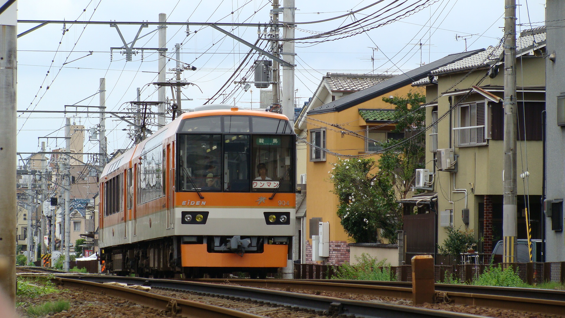
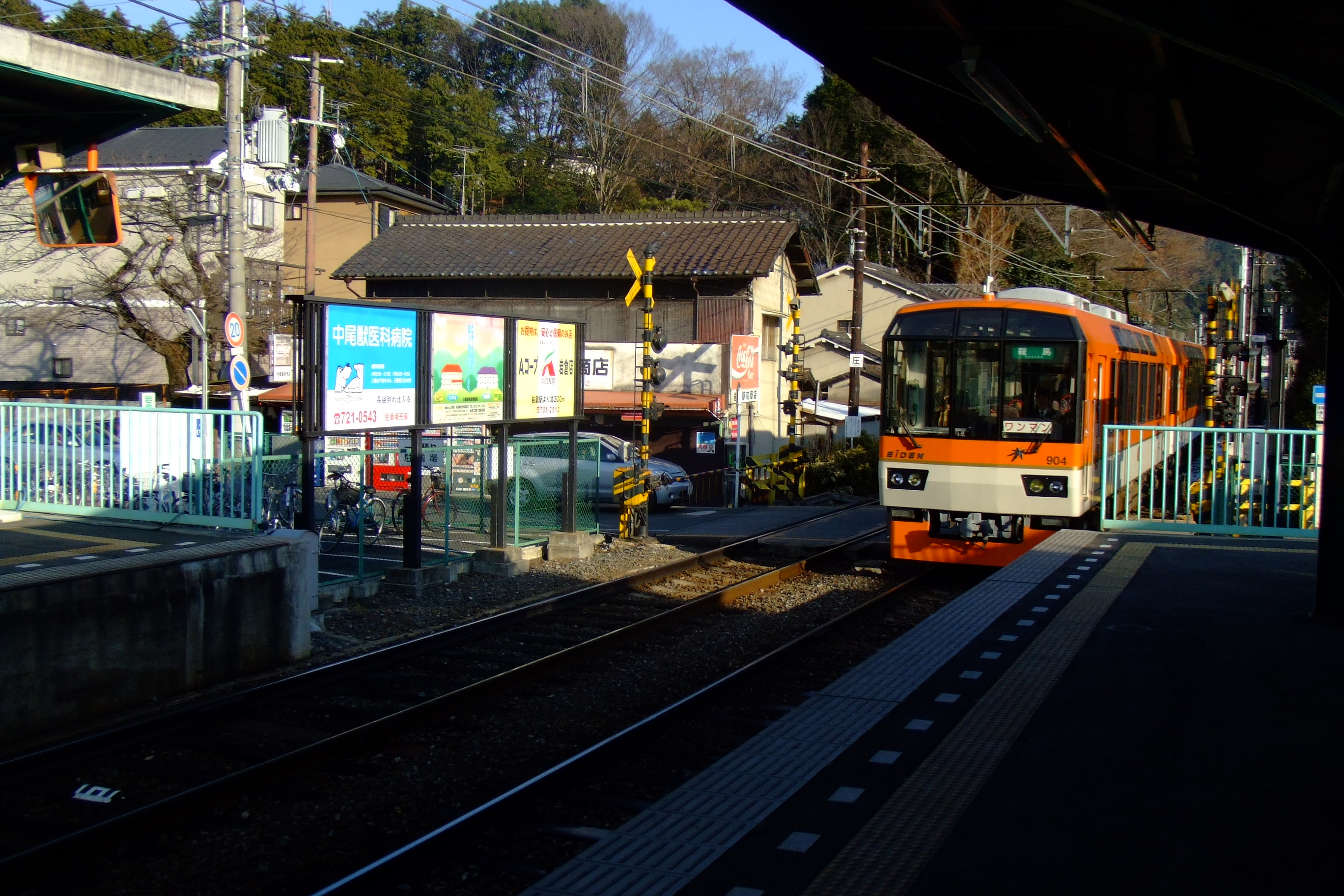
And then my favourite, the Deo 'Kirara' 900 Series. This model was released by Kato and I have it in both the Maple Orange and Maple Red. It also received a prize (can't remember the exact name, 'Lauriel?') for it's design. It's internal seating allows the passengers to sit sideways and view the scenery along the route. It also has high observation windows.
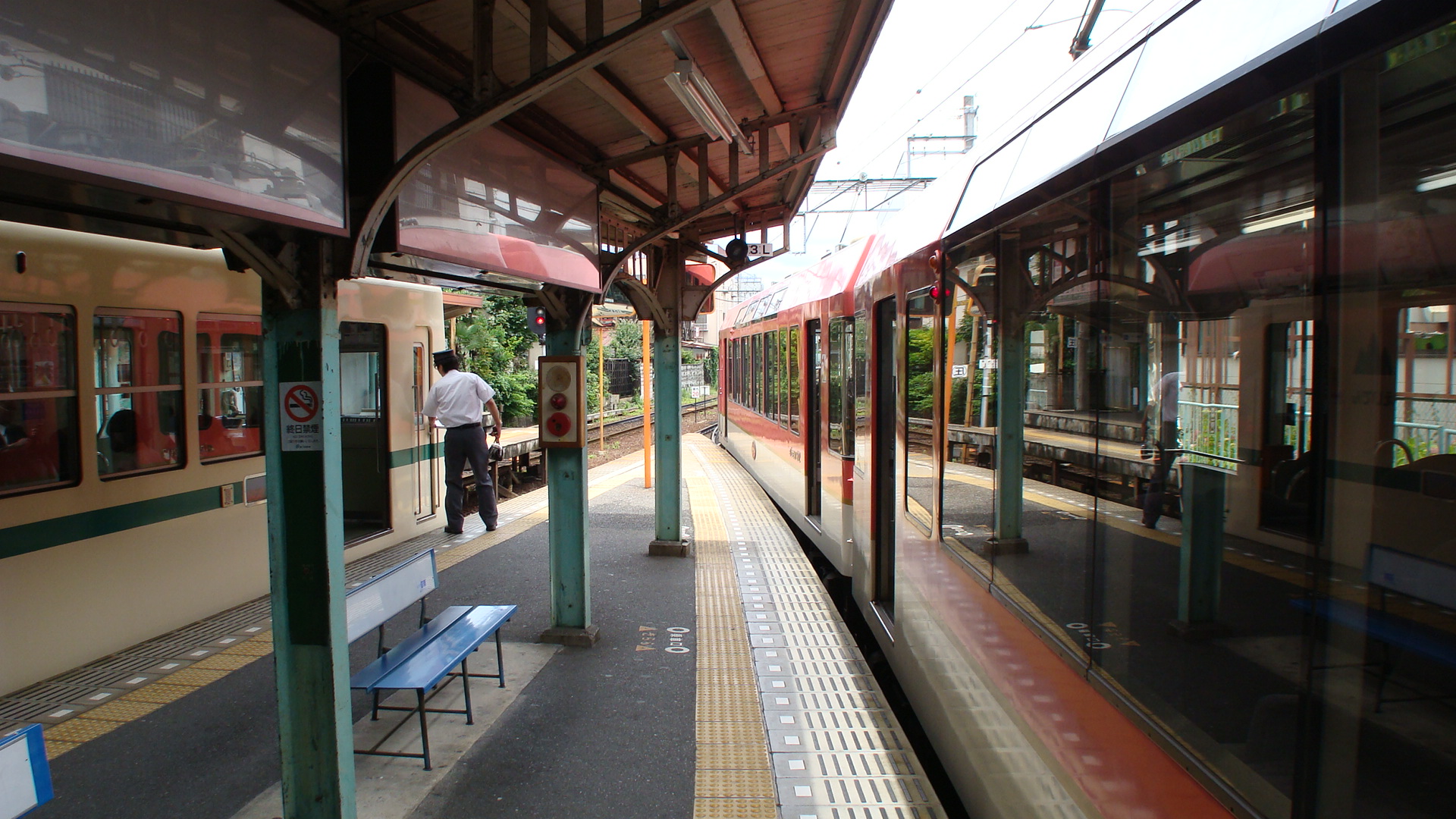
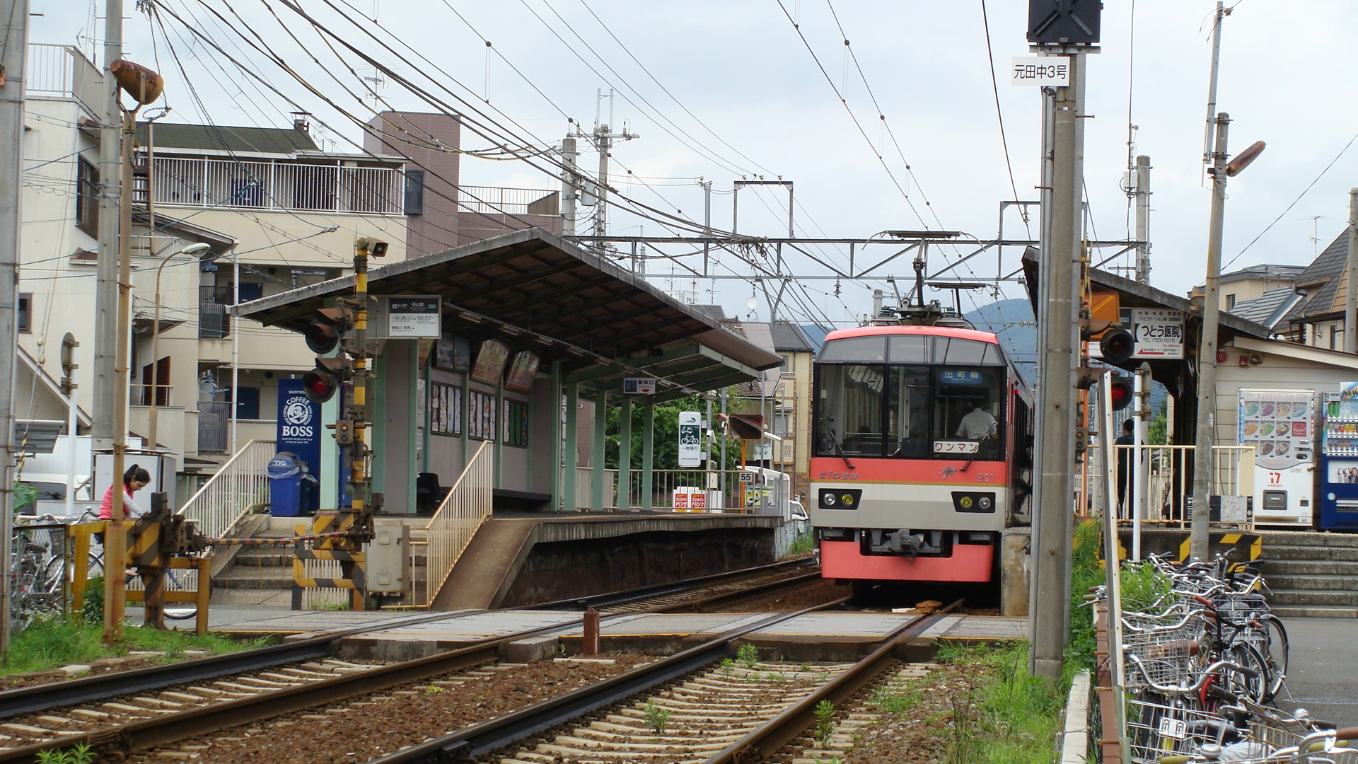
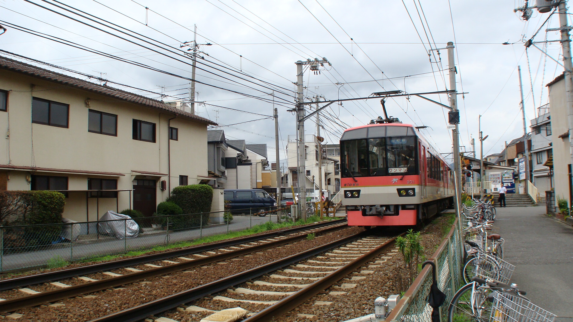
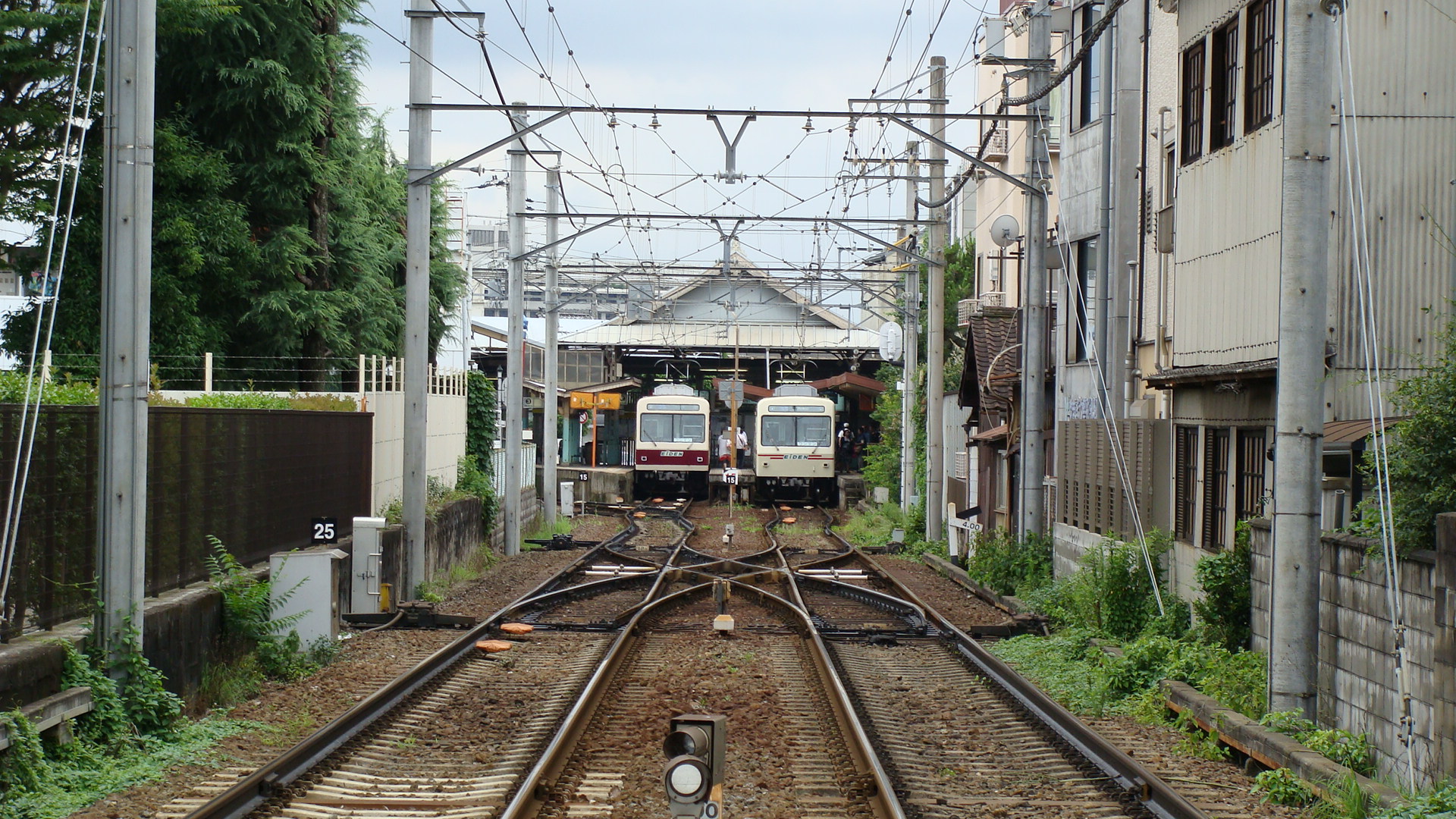
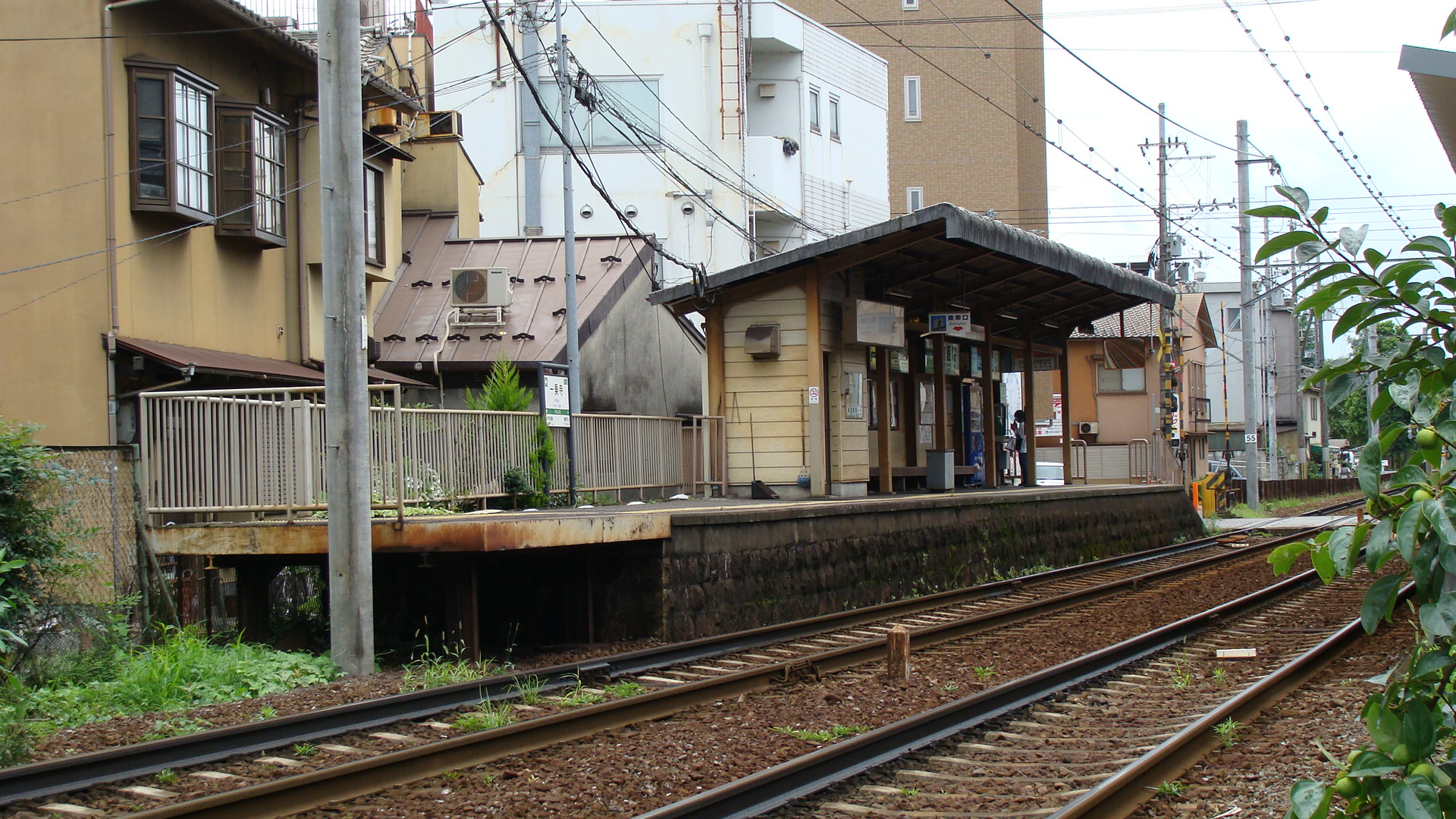
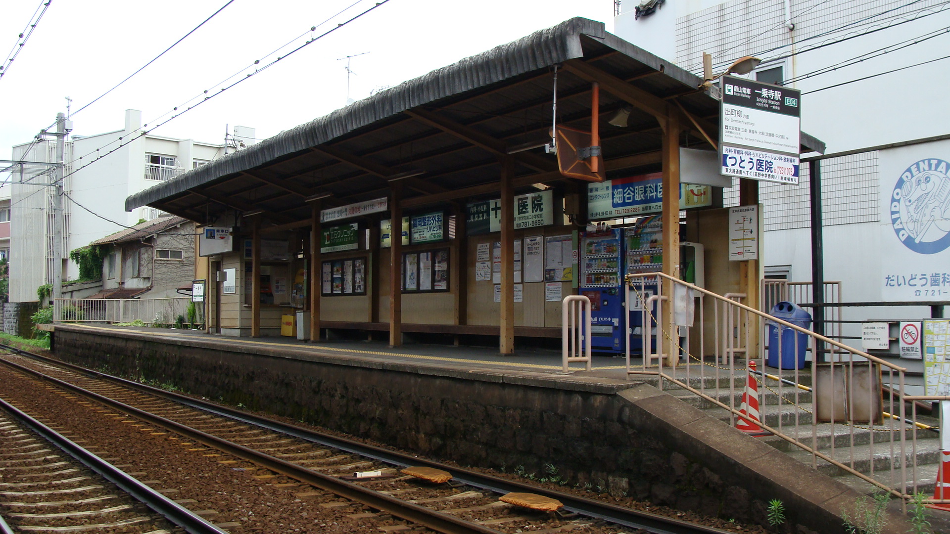
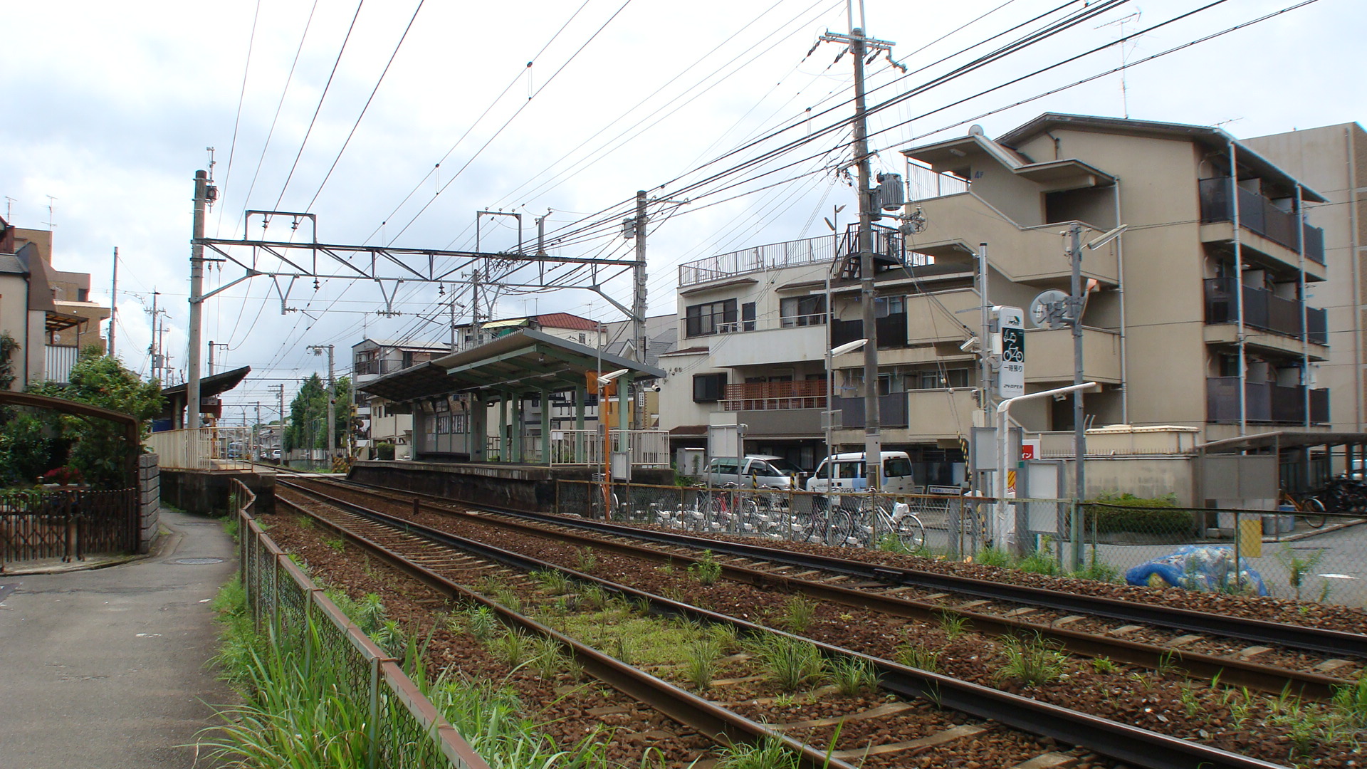
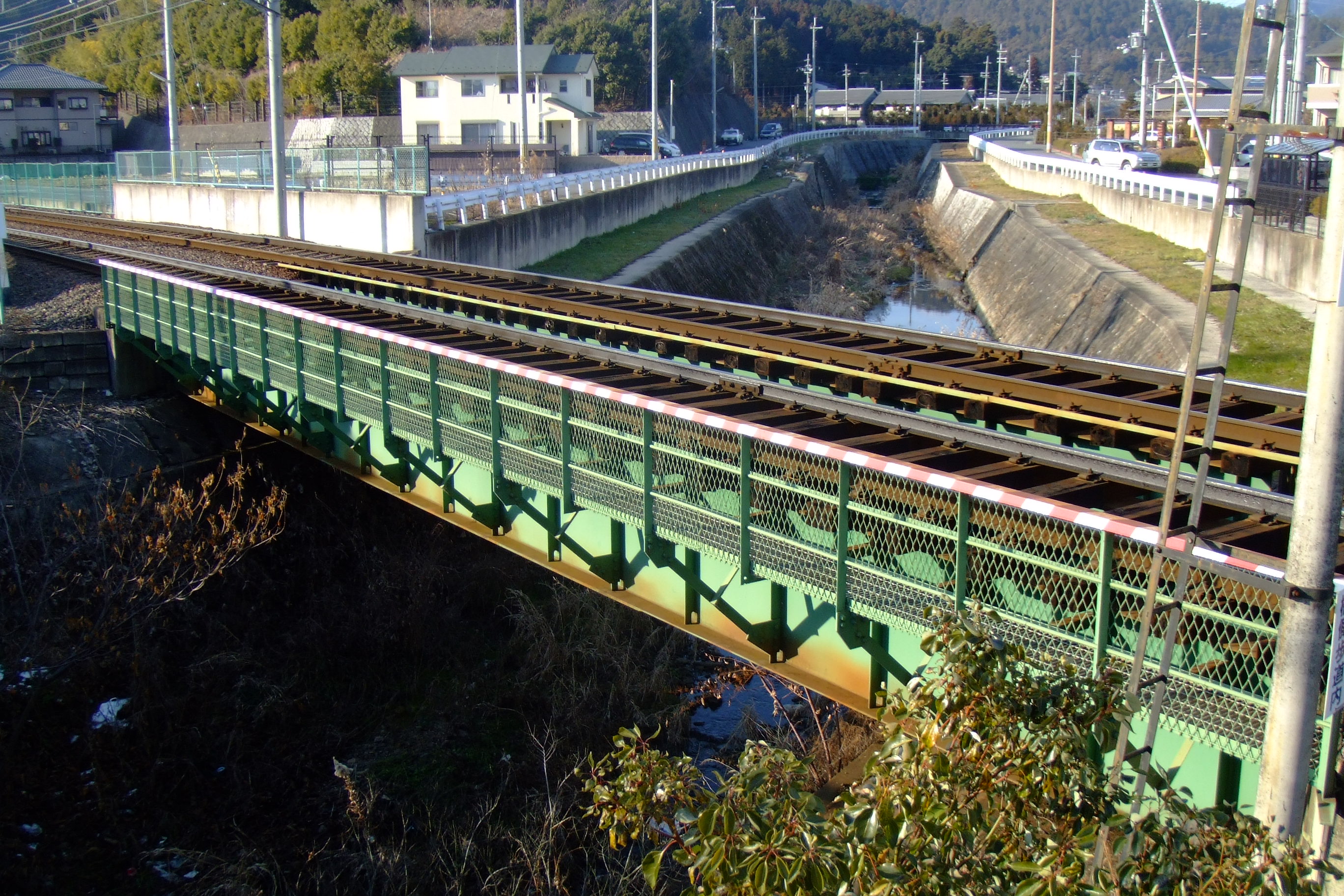
Stations and Facilities
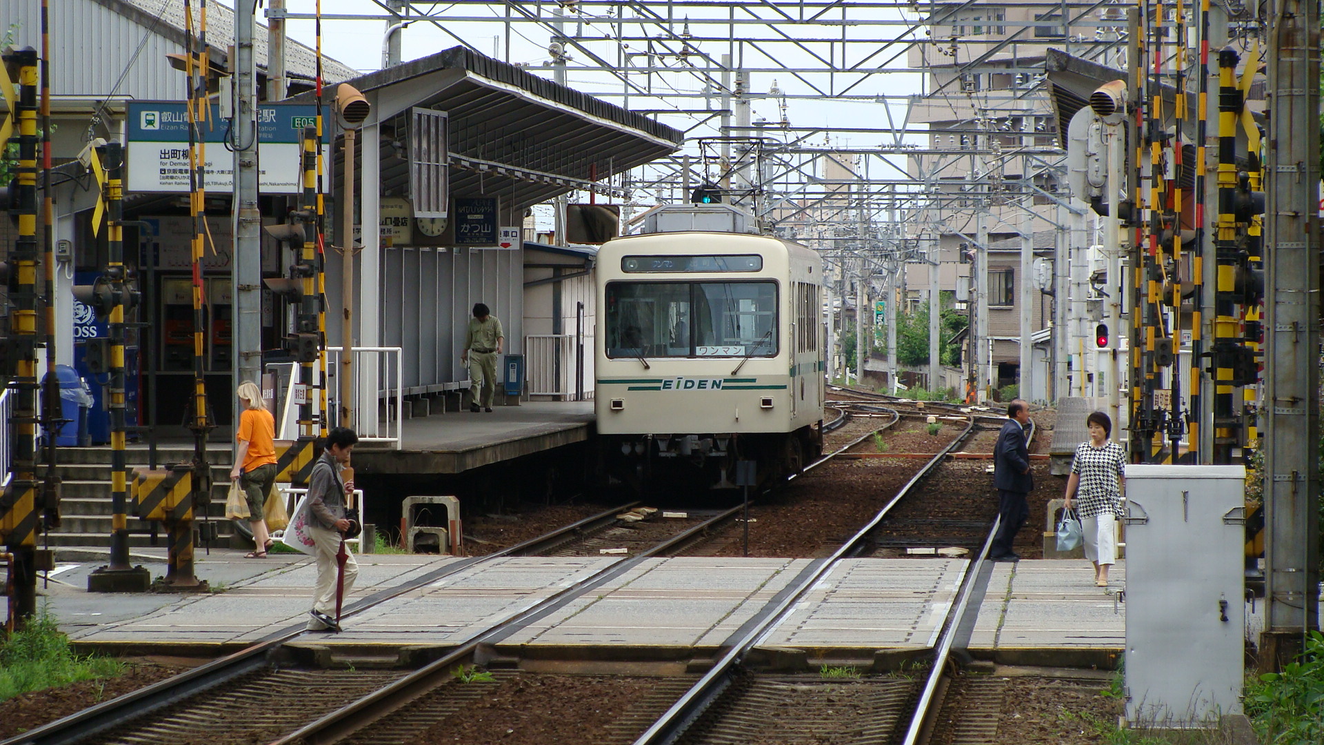
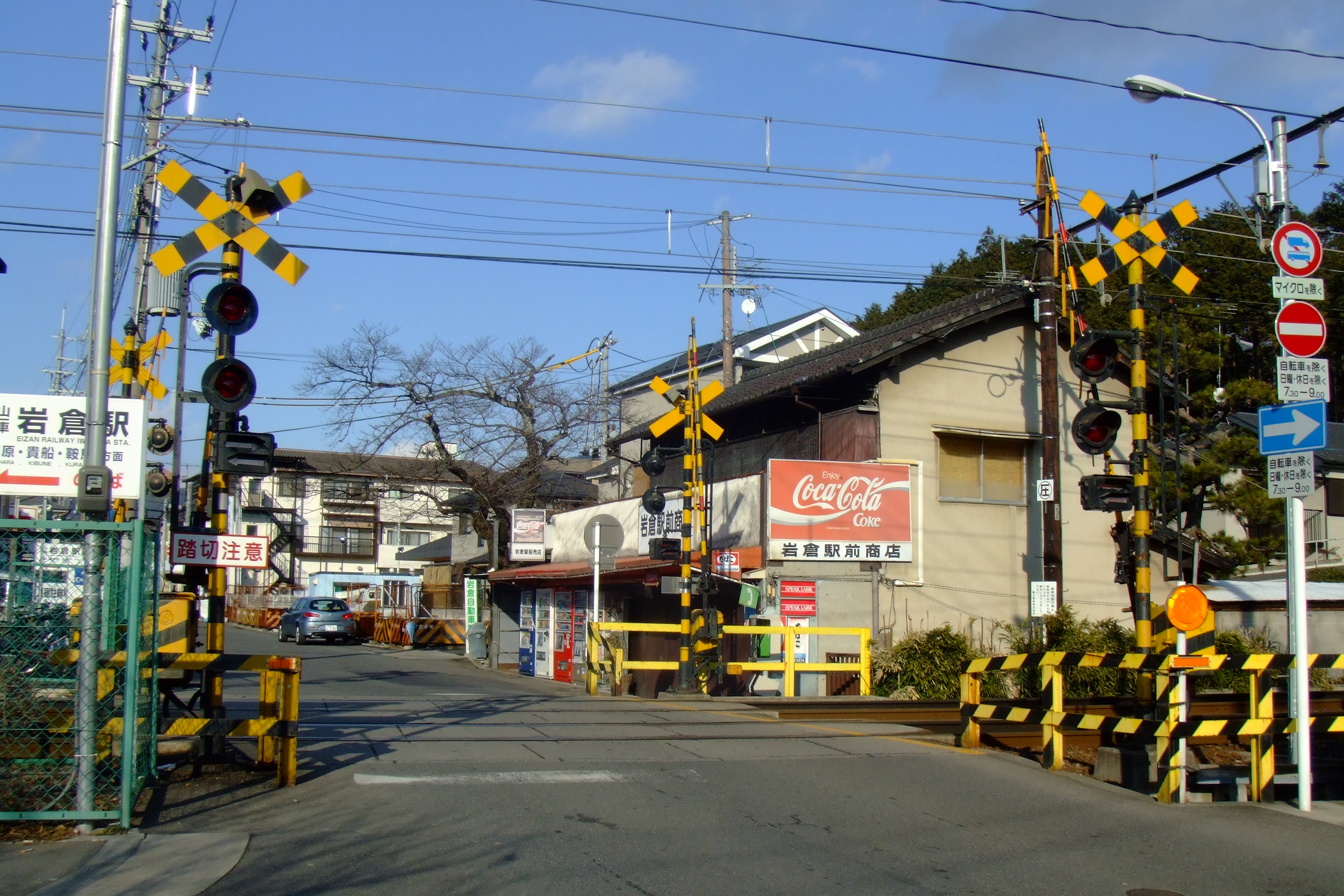
Ichiooji Station
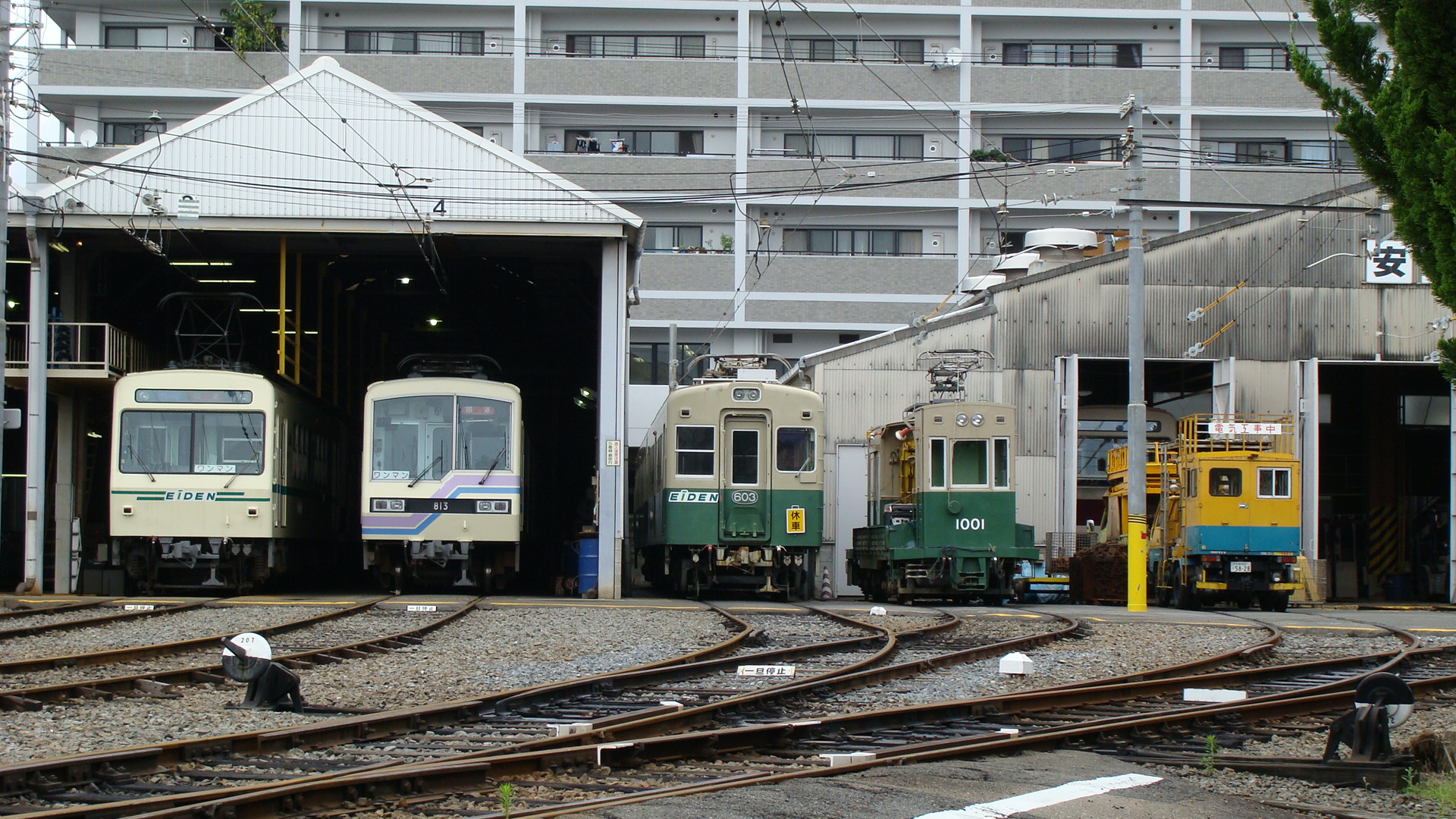
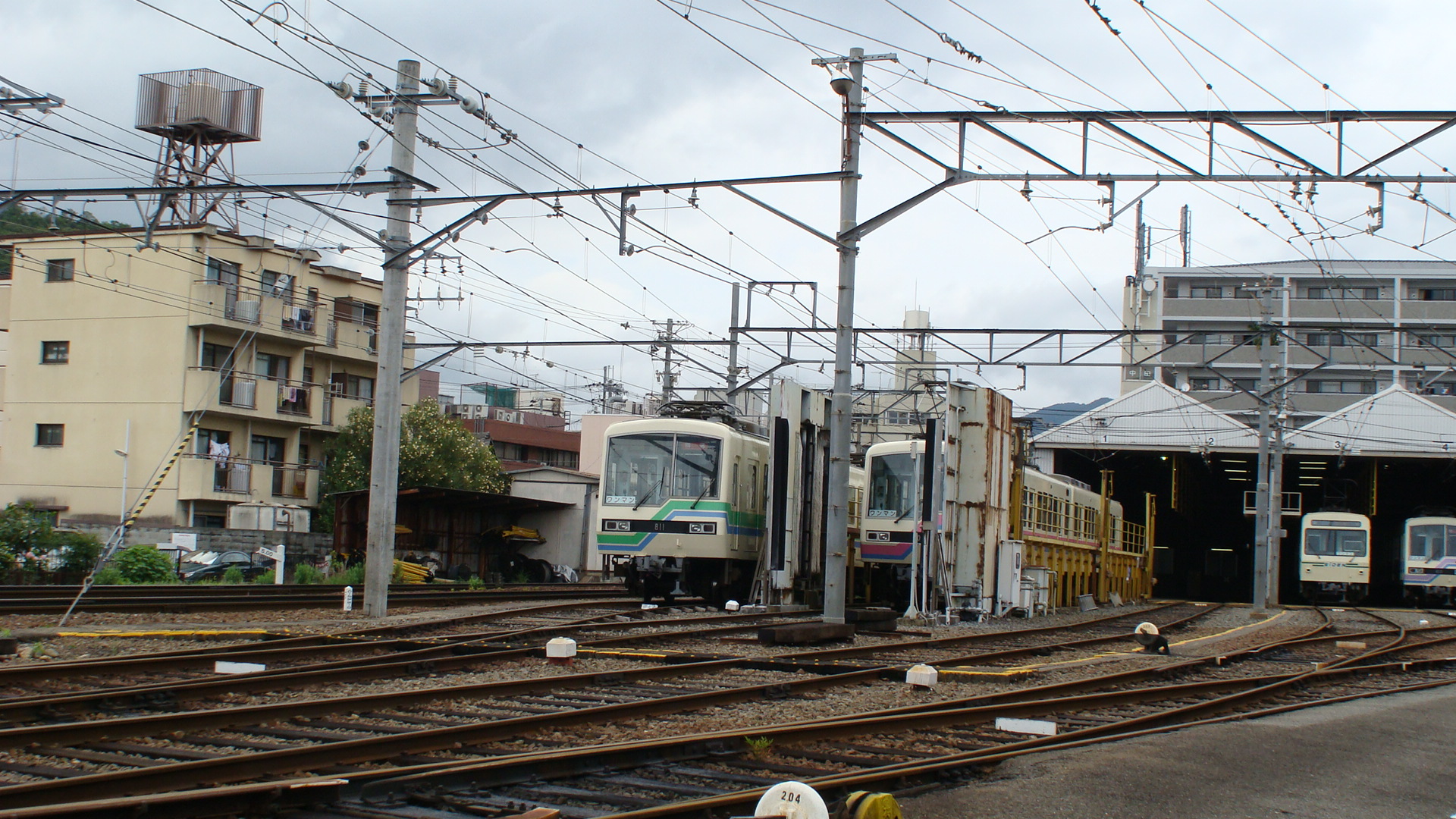
Shugakuin Depot
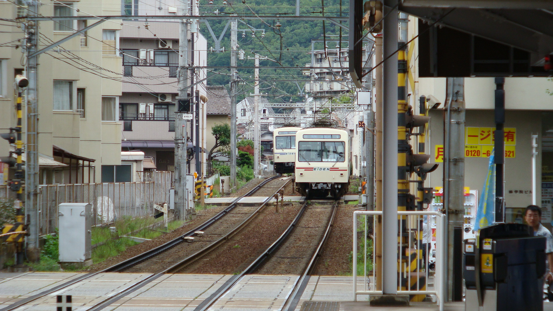
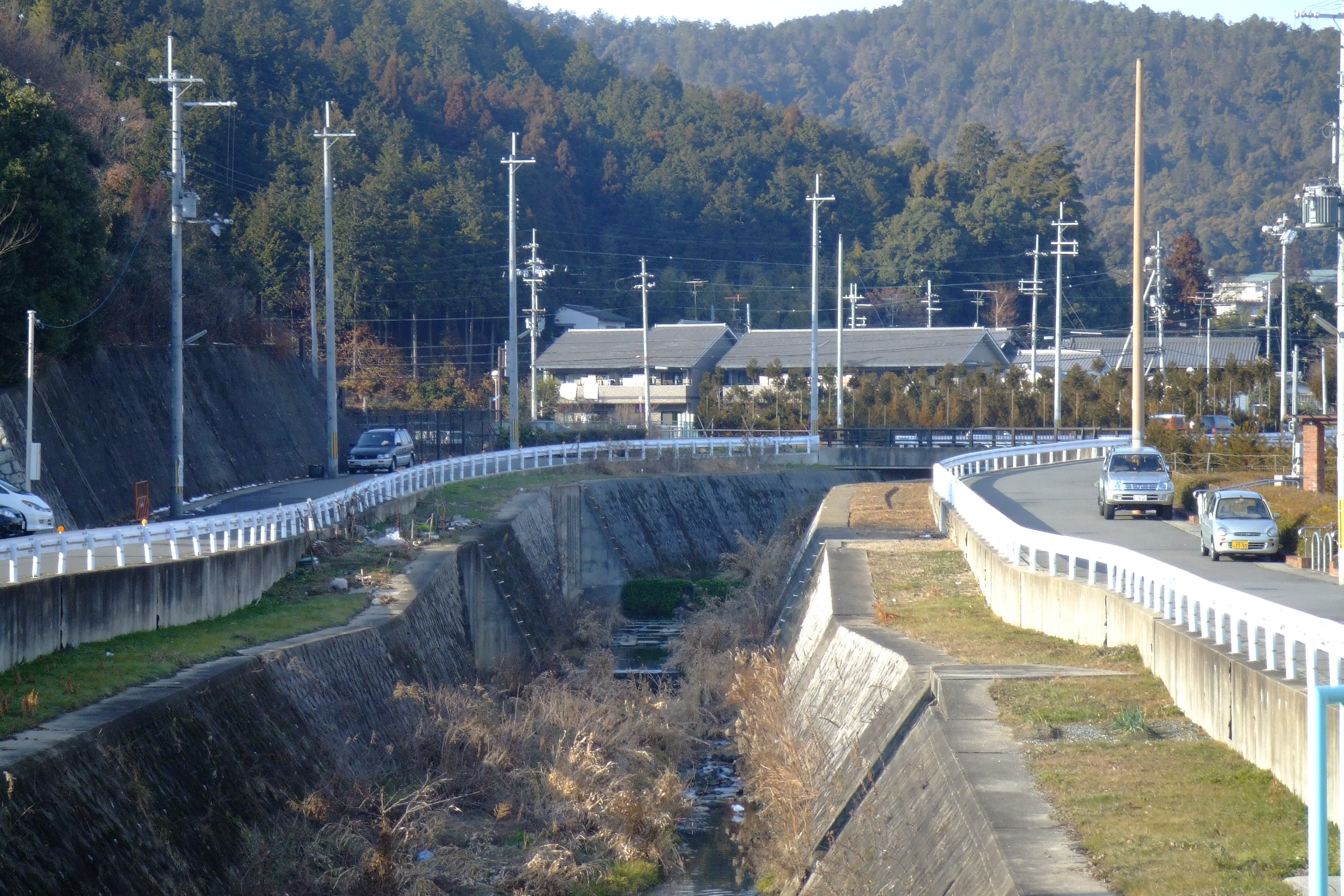
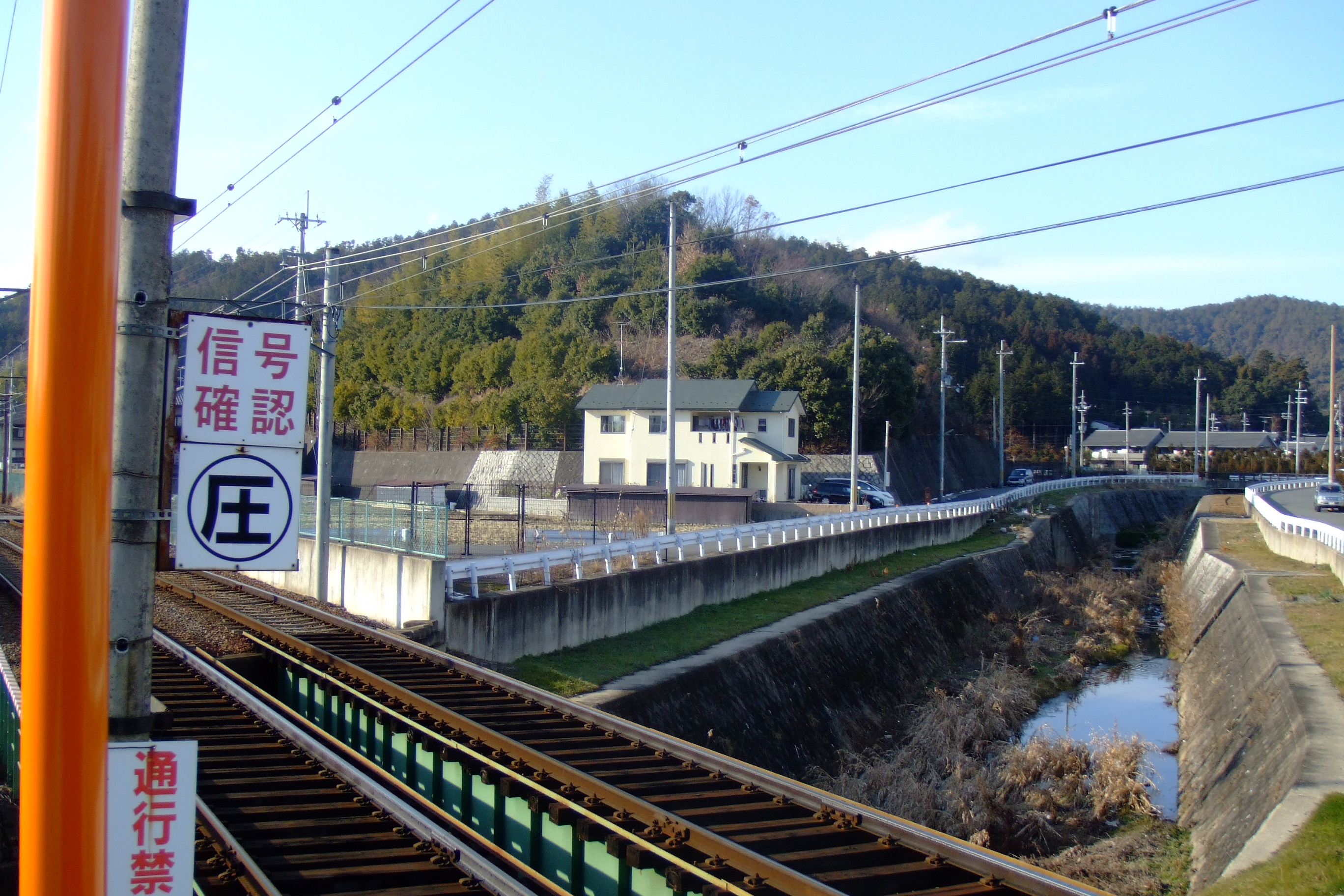
Iwakura Station
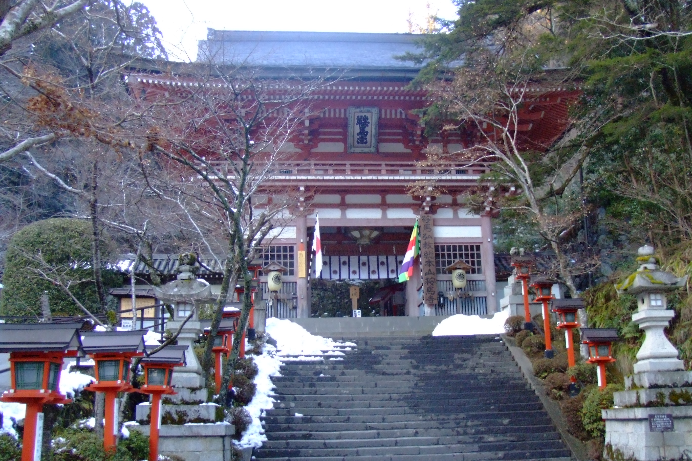
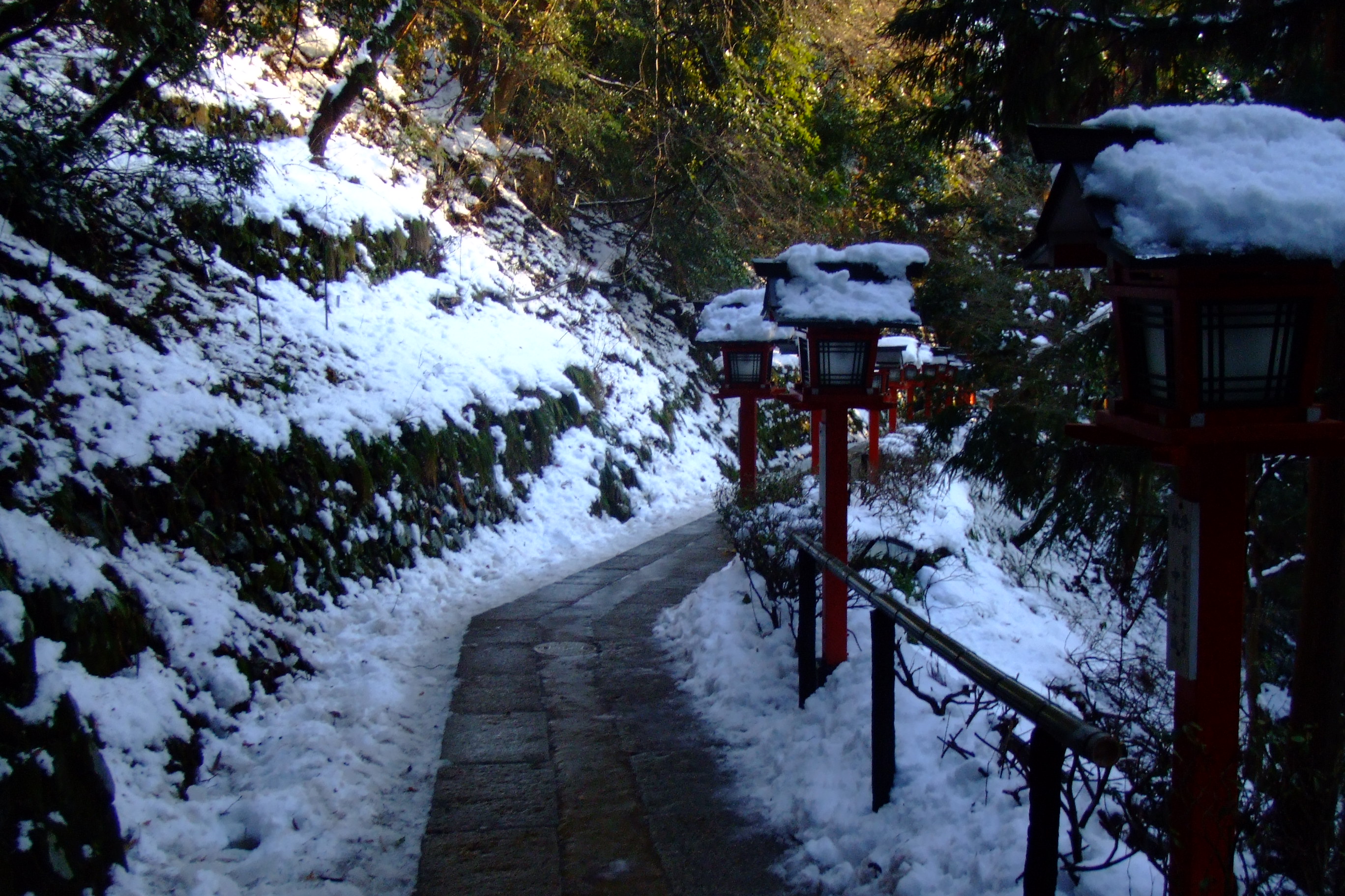
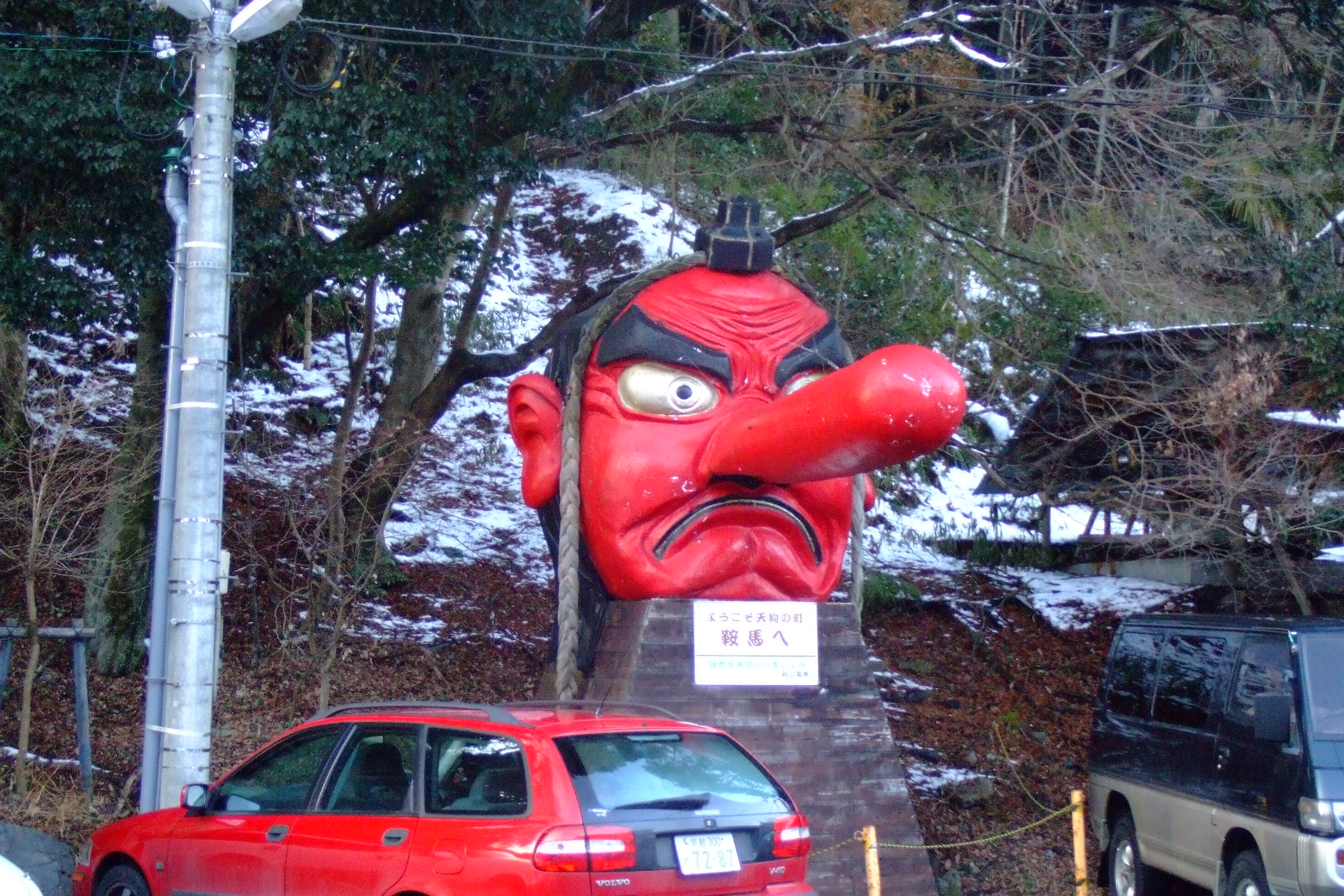
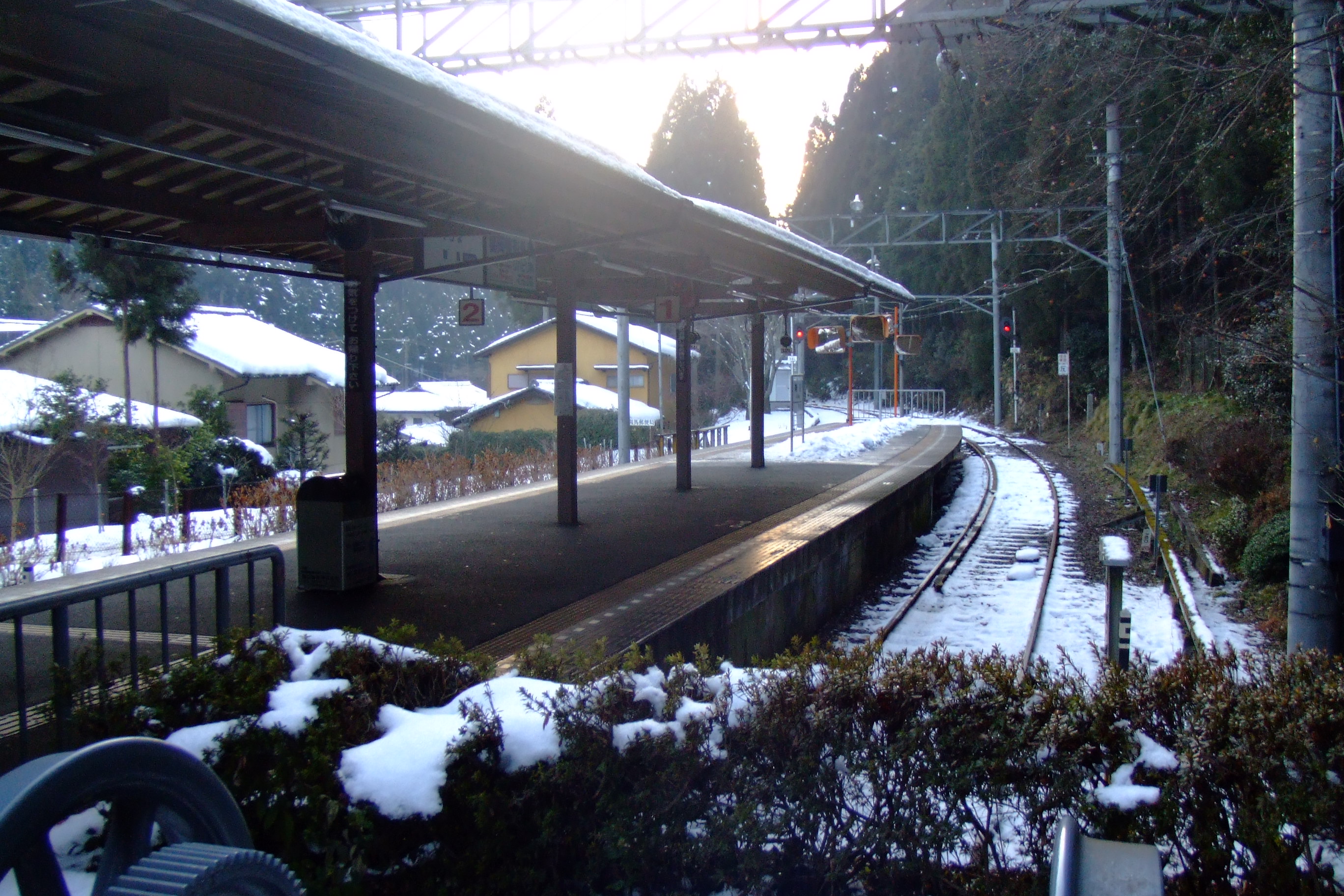
Kurama
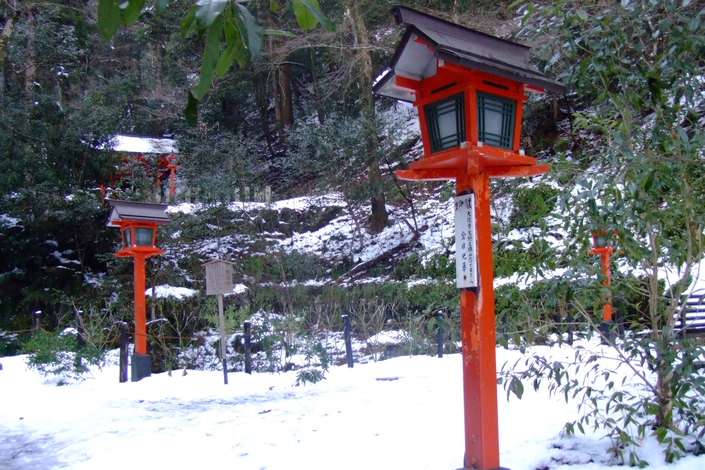
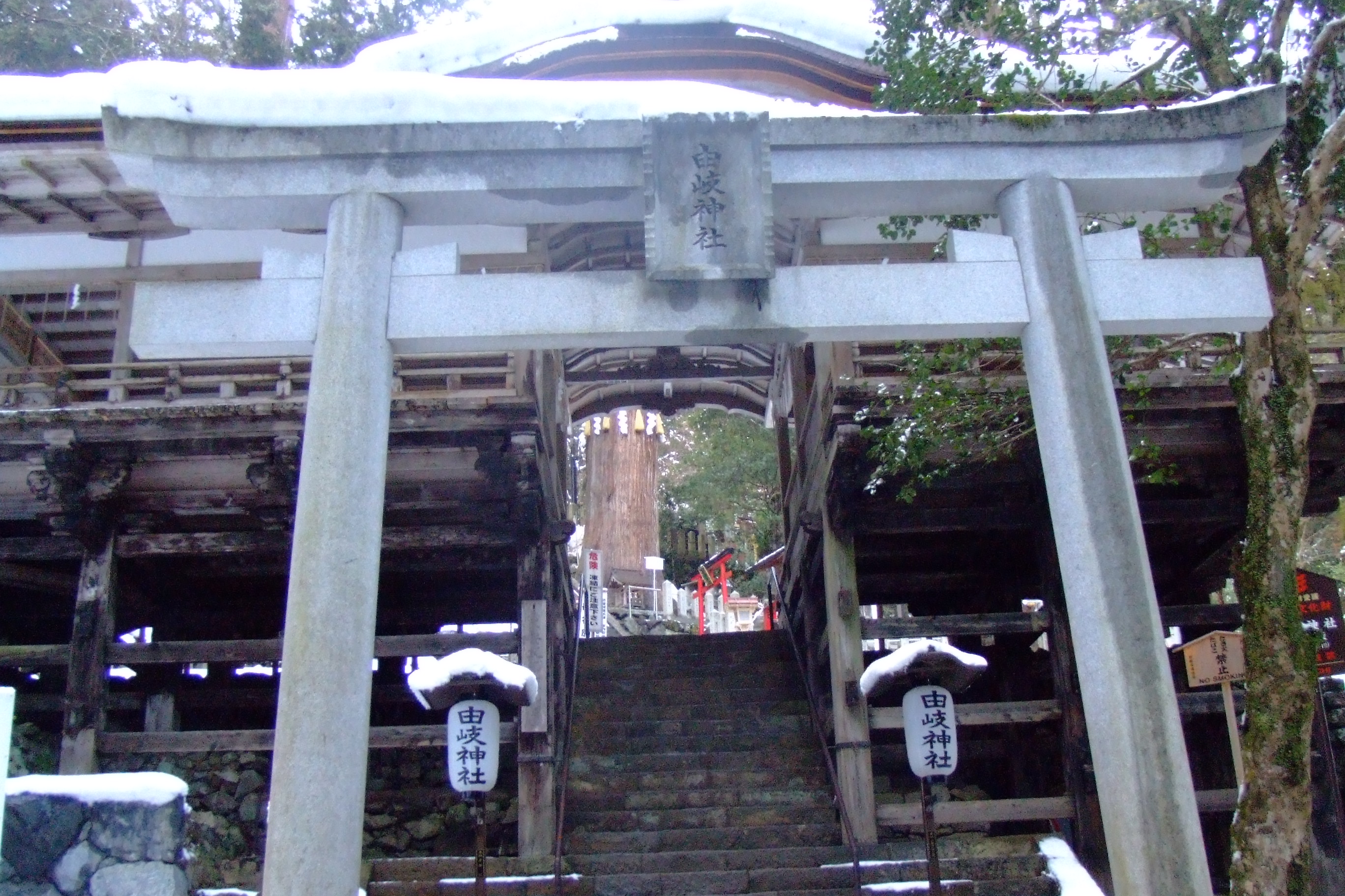
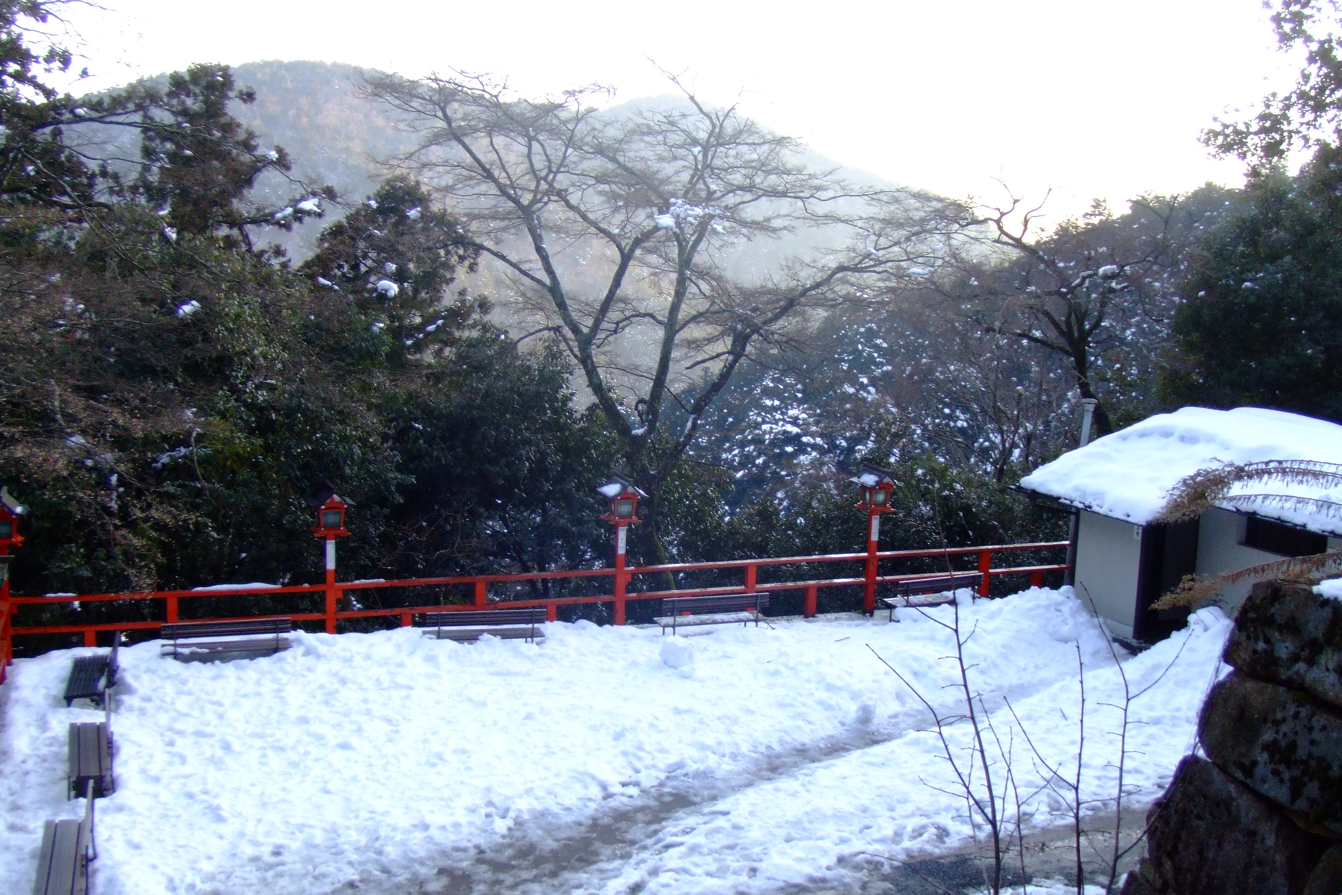
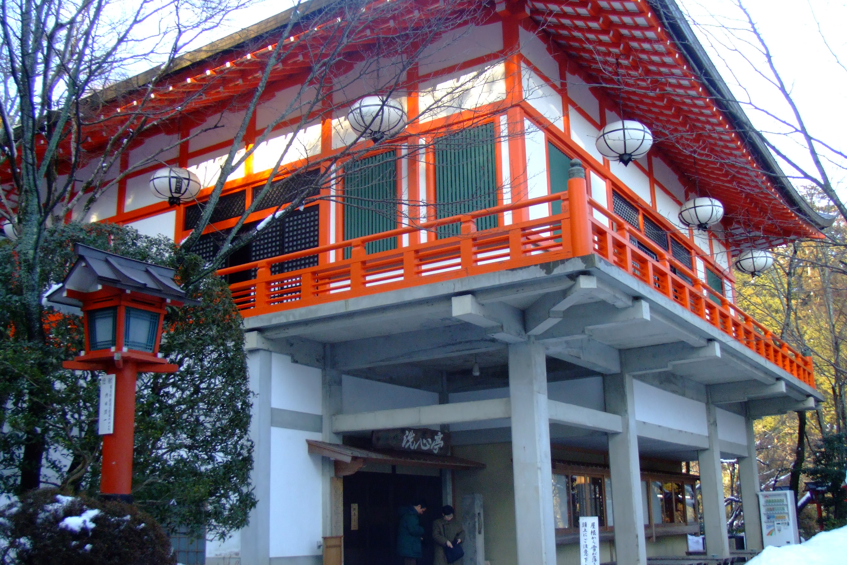
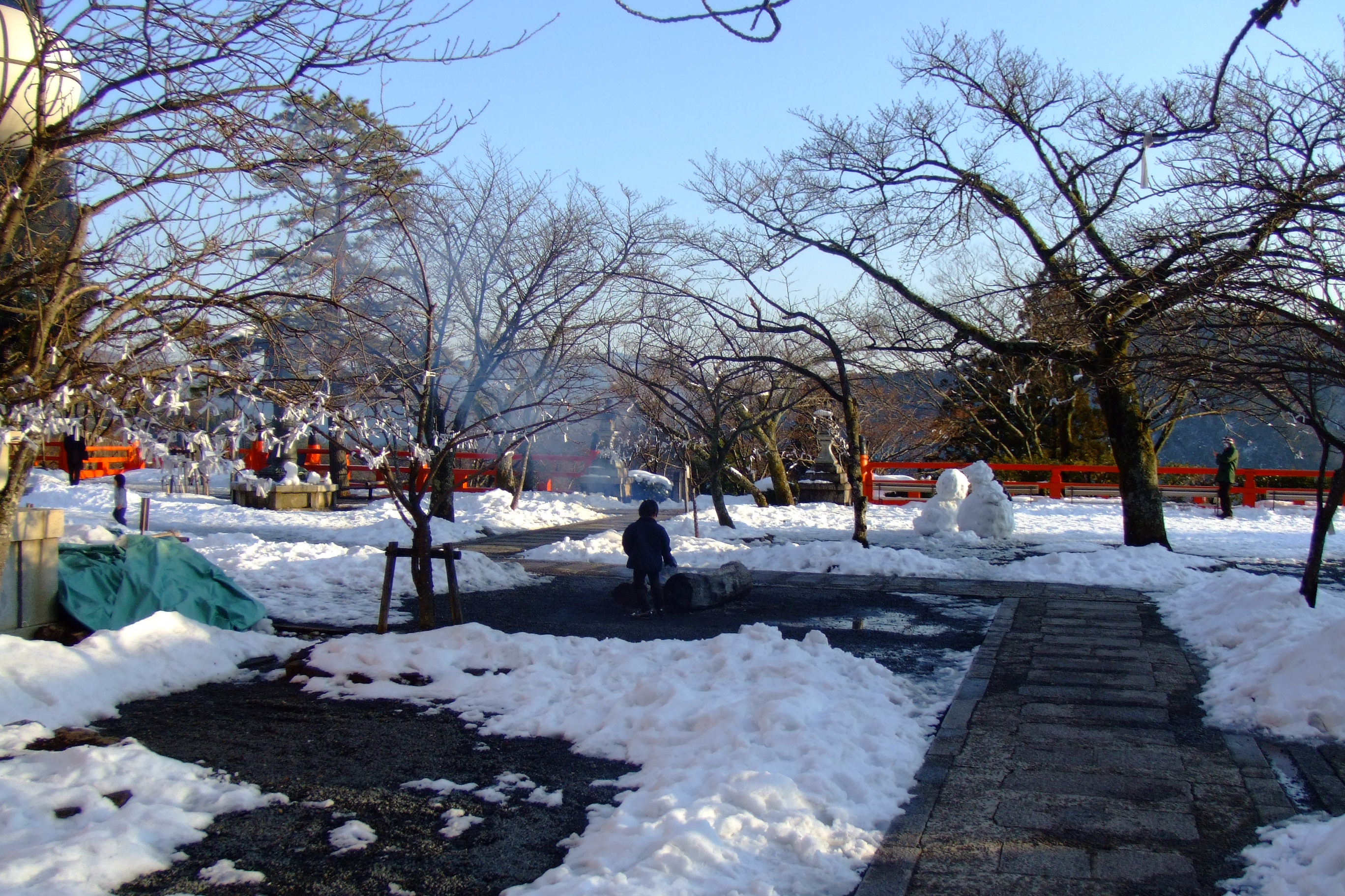
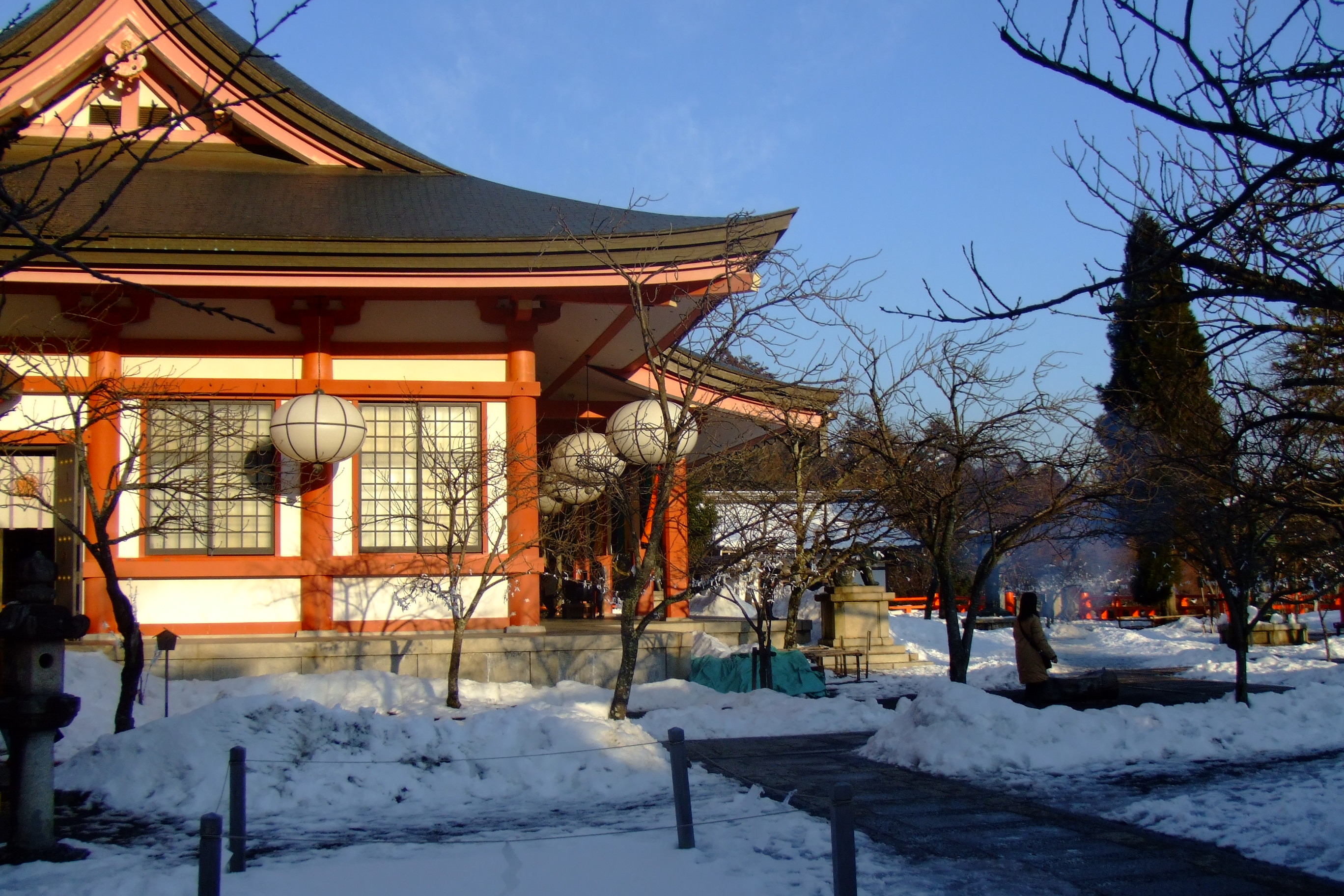
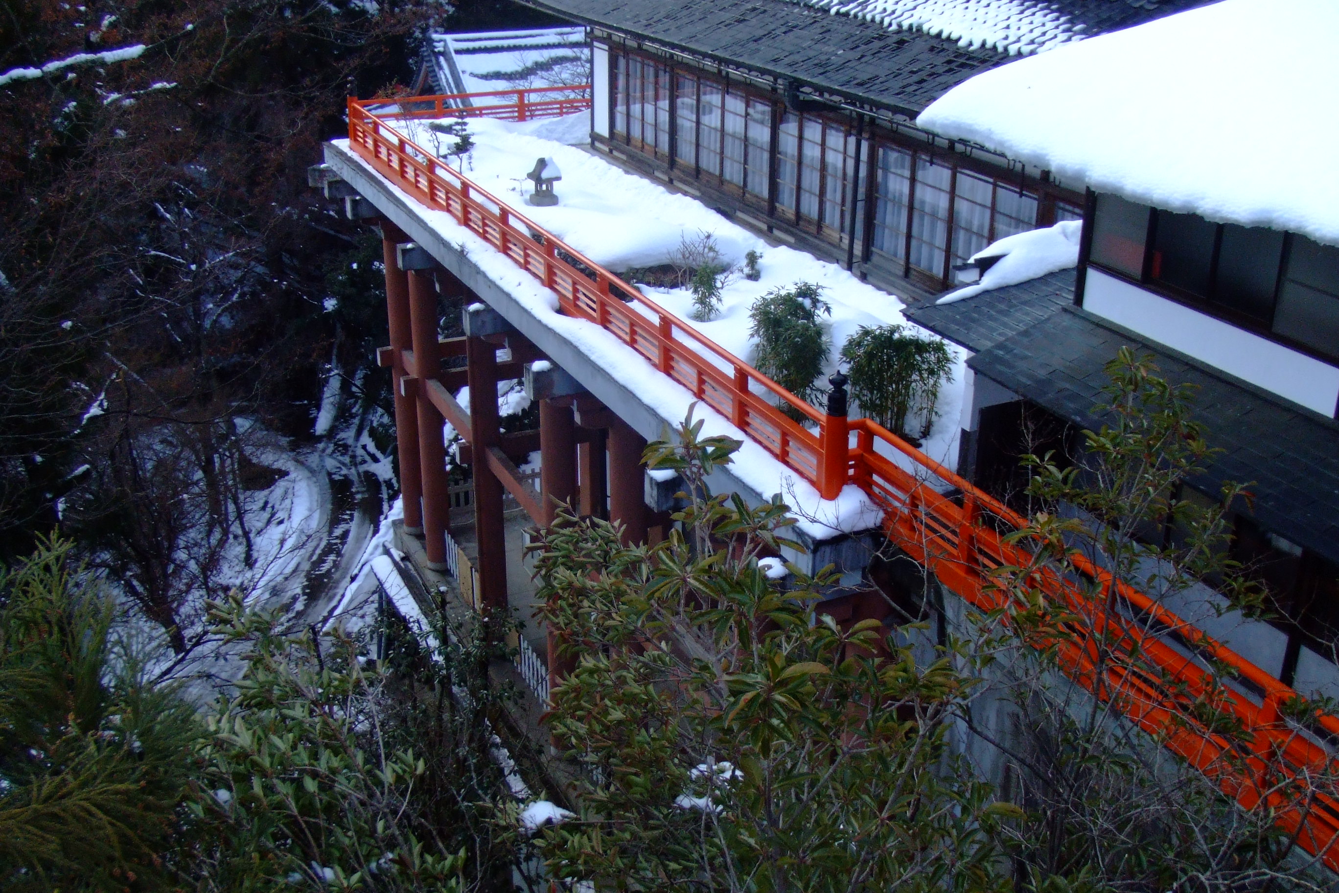
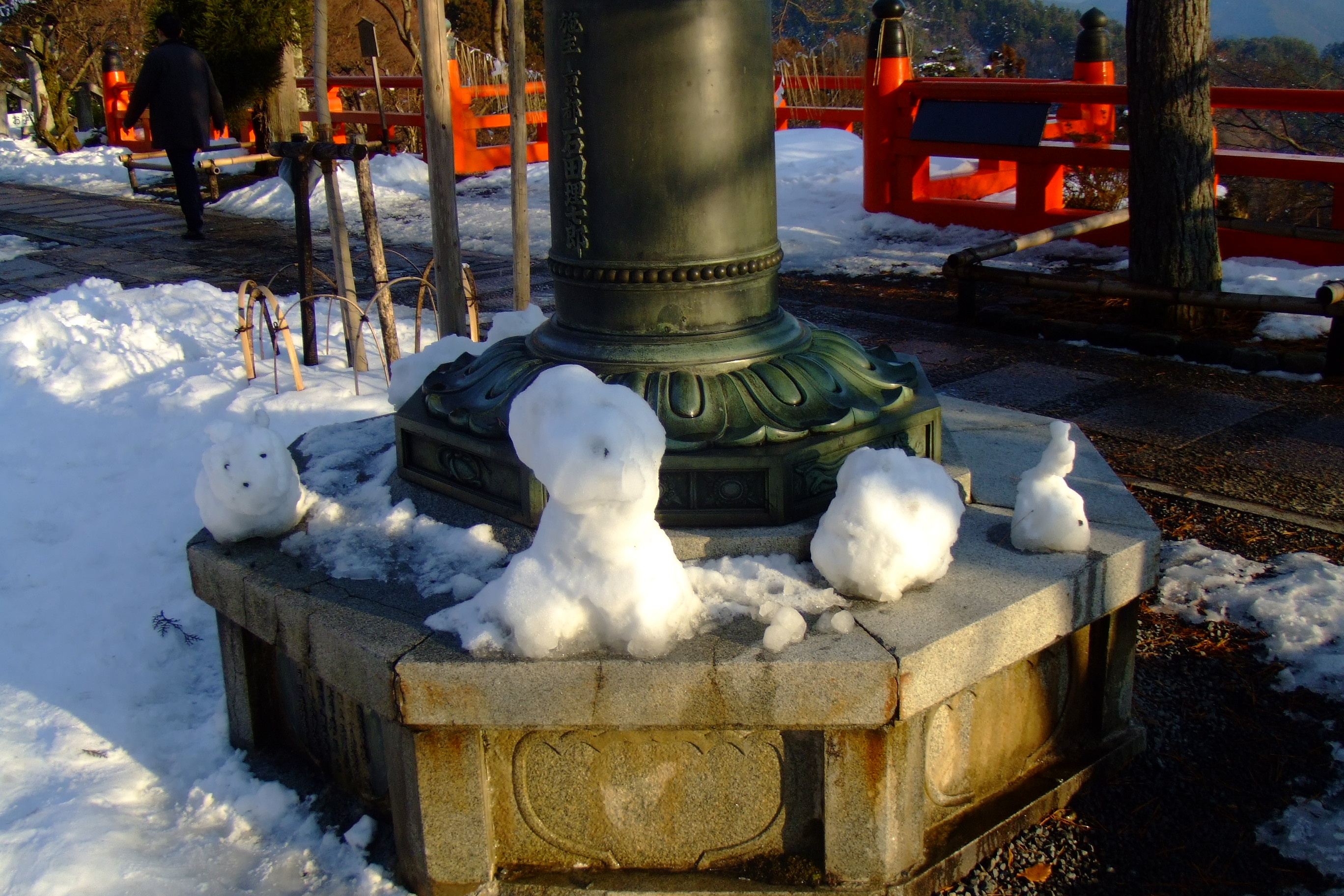
After getting off at the final stop, passengers transfer onto the Cable car and end up at Kurama. Here you'll find a temple and an onsen. Be careful though, I visited here in Winter of 2005 and it was very slippery and dangerous! (Then again, I'm probably just from Australia and don't understand snow :))
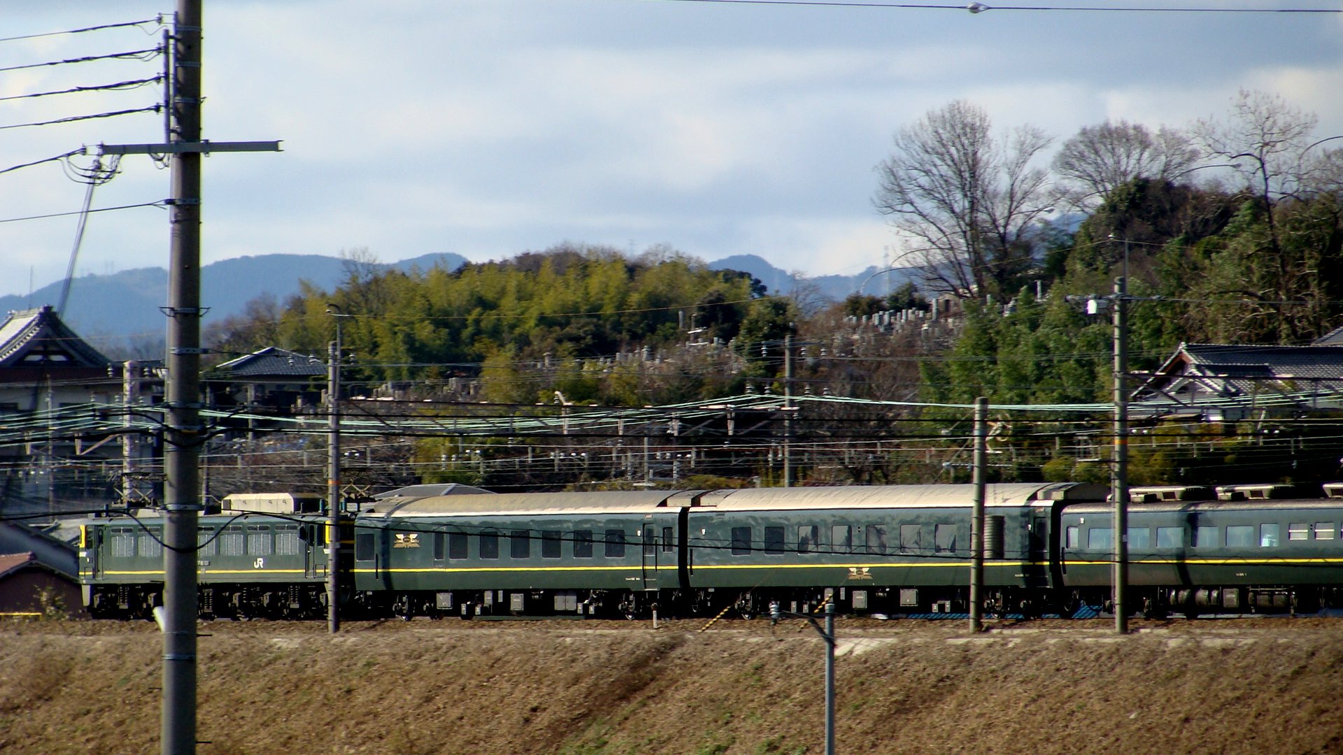
Japanese Night Trains: Twilight Express
Night trains are becoming a thing of the past in Japan; but there should be a few that survive... hopefully the Twilight Express is one of them. This overnight sleeper train starts in Osaka and terminates in Sapporo, Hokkaido (and vice-versa.) The trip takes roughly 23 hours and traverses the west coast of the main island of Japan. There are two full consists of the Twilight Express to allow daily services from each end of the trip.
Sightings
I'd seen the train in Japan when I was there in 2008 but hadn't even thought of travelling on it.
A ticket in hand
My next trip to Japan was to be in 2009 and I was determined to get on the train. I hadn't had many spare nights in Japan and the train had been booked out between Osaka and Sapporo on the nights I did have spare. This didn't deter me though, as the reverse trip wasn't booked out. Of course, I then had to get to Hokkaido first and I therefore took the Nihonkai (another sleeper train) to Higashi-Muroran (Hokkaido) and intercepted the Twilight Express as it returned to Osaka. I wasn't able to get all the way to Sapporo in time to meet the Twilight Express there. Higashi-Muroran was pretty cold; although it was the start of the Japanese summer, Hokkaido was still in the low teens (degrees) and I wasn't prepared.
The Nihonkai had arrived on time, giving me a 2 hour stop-over in Higashi-Muroran. There wasn't much rail traffic and so I ran to the nearest katsu curry restaurant to have my favourite dish. On returning to the station I didn't have to wait long to see those familiar blue DD51 diesels arrive. Of course, the lighting was dismal and my digital camera had no chance of catching them moving... I also had no time of getting to the front of the train to take a still shot.
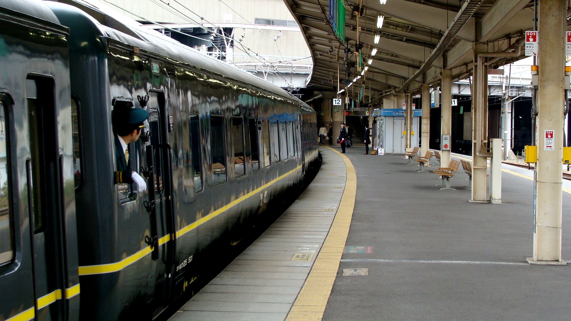
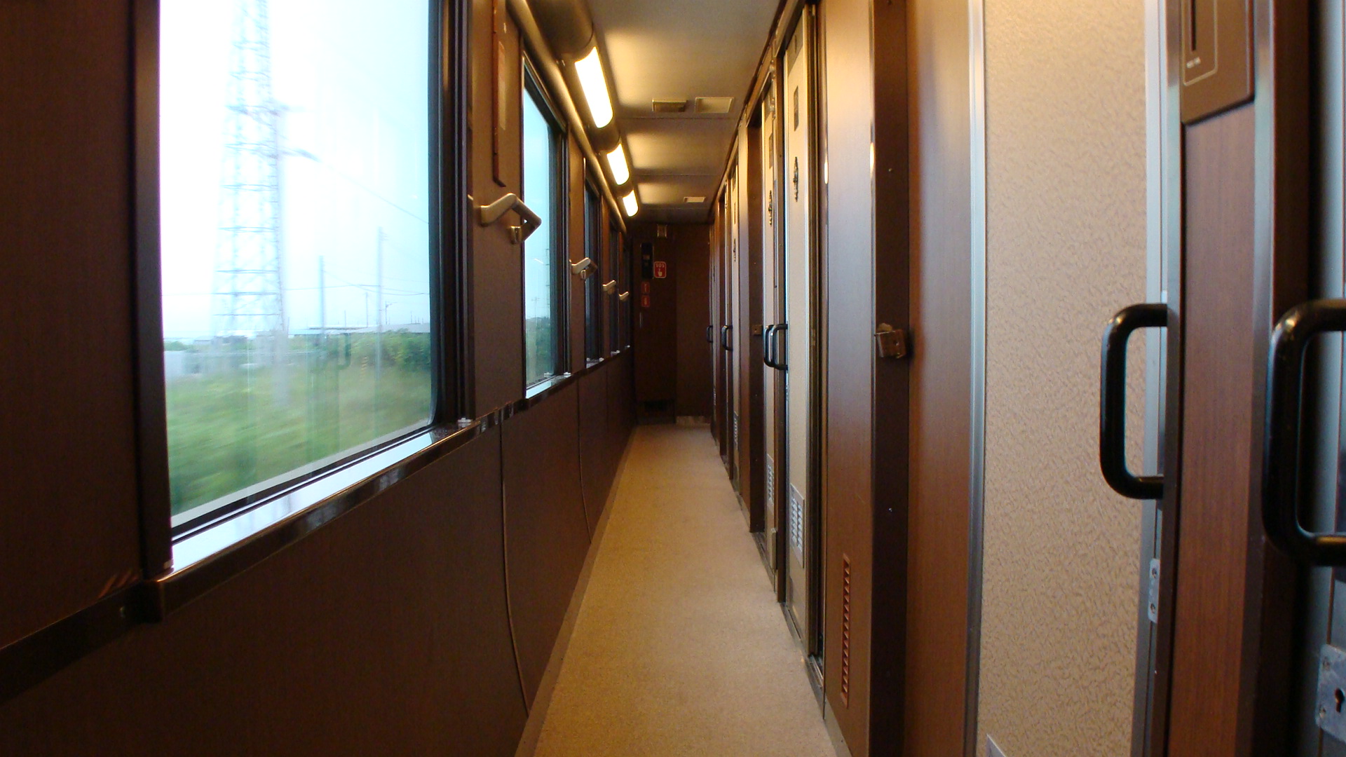
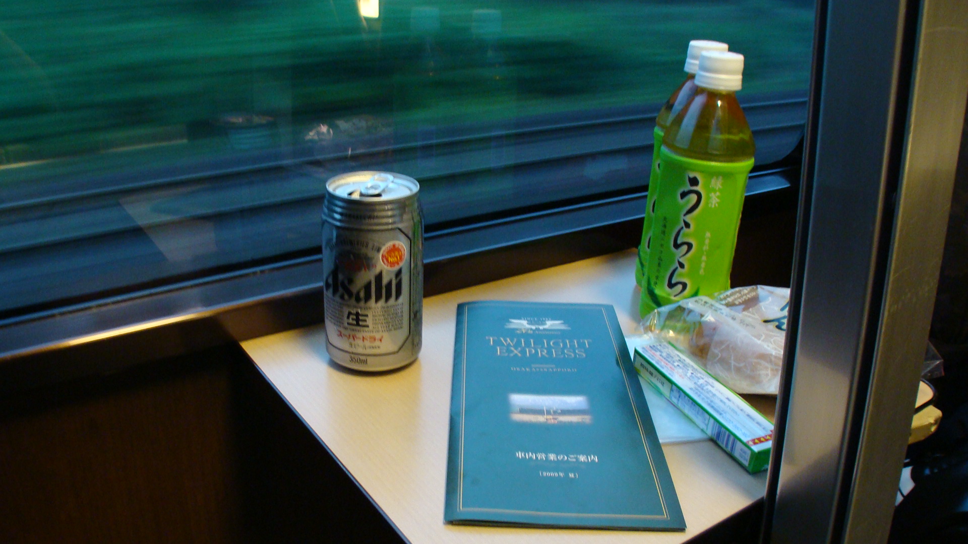
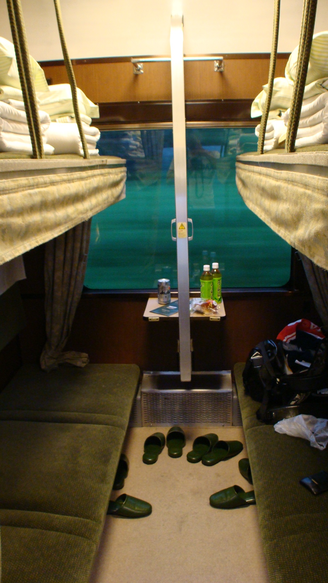
First impressions
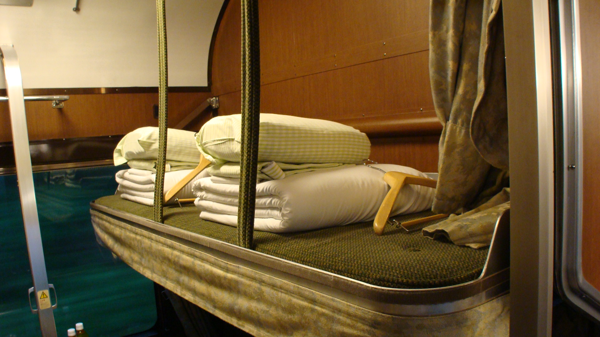
Upon entering the car (I was in a B Class Sleeper) I was presented with beautiful wooden walls and very well kept rooms. As you can tell, I settled in pretty quickly... I'd also brought a few goodies on board. The conductor came in quite soon after to say hello and to apologise for not being able to speak English. Fortunately, my limited Japanese meant we could work out all the formalities: the coin-operated shower was in the Salon Du Nord car, dinner was in allocated time slots: 7pm,8pm,9pm (if I remember correctly) and finally I had to choose what 'type' of meal I wanted for dinner and breakfast? Japanese or Western... I wasn't on the train for Western food!
I then realised I wasn't alone in my cabin and started making new friends. Soon enough another conductor came and found me and offered to change me into another room (still a B Class 4-person) but with me being the only occupant. I couldn't turn down their hospitality and so obliged.
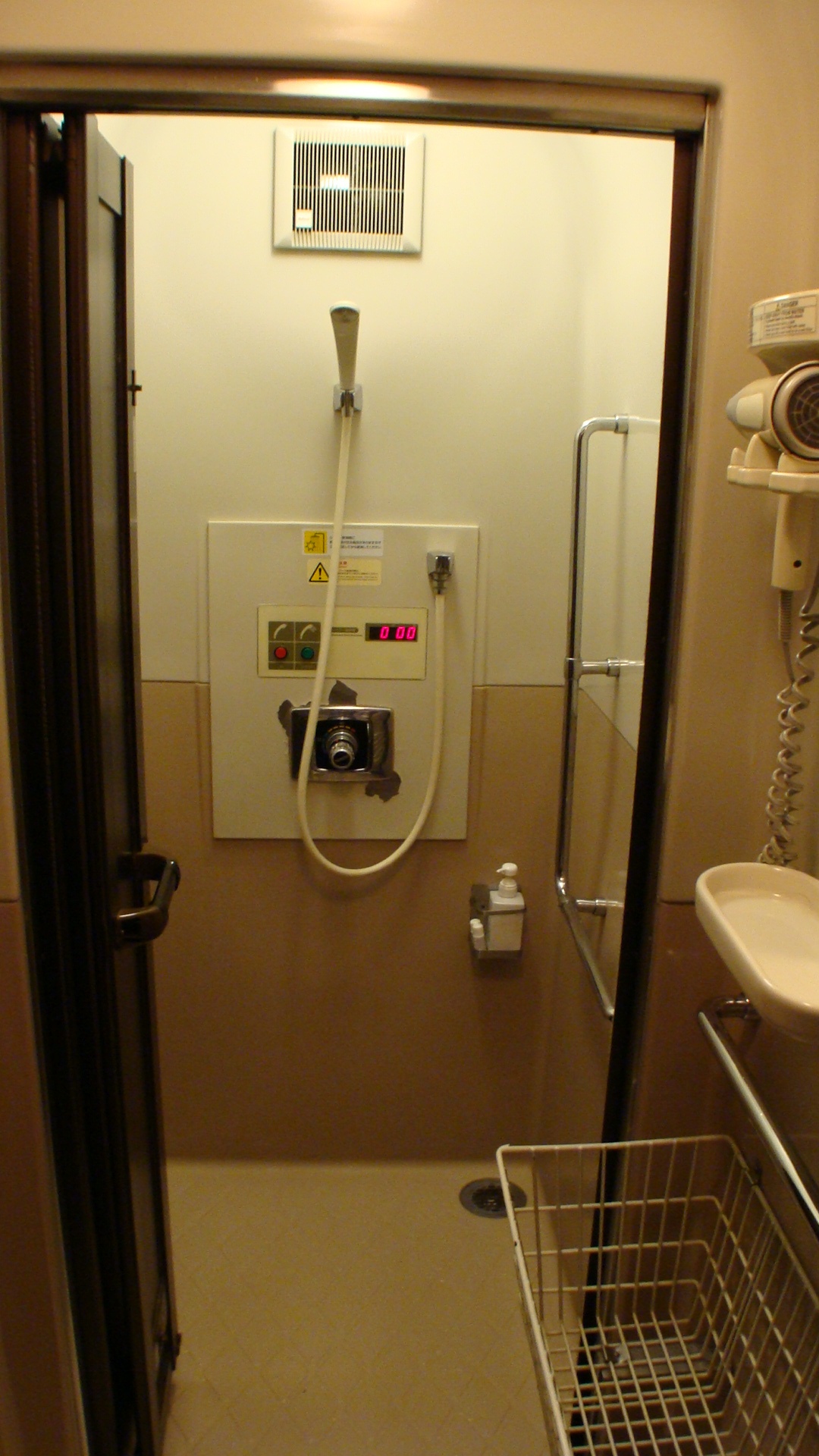
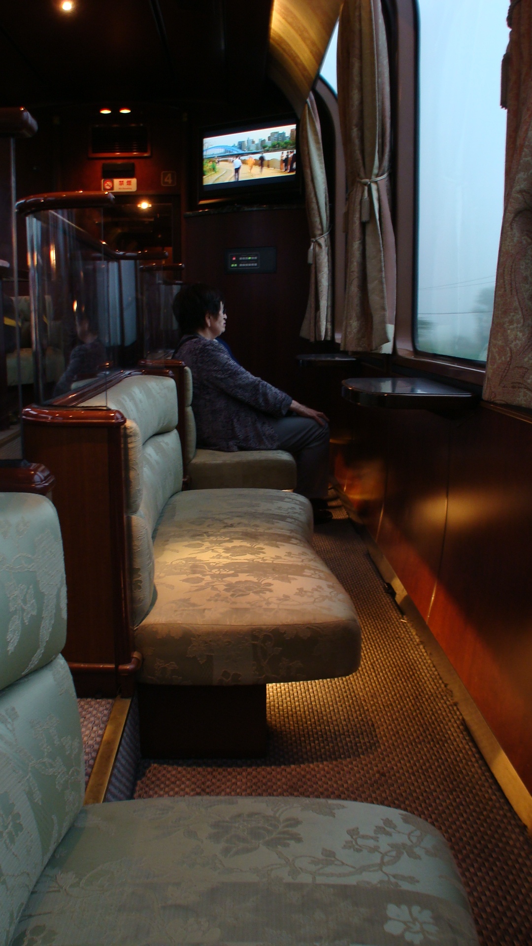
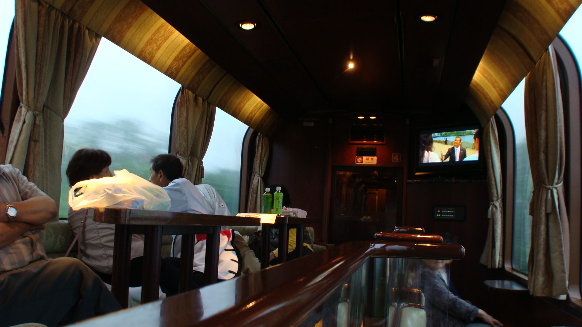
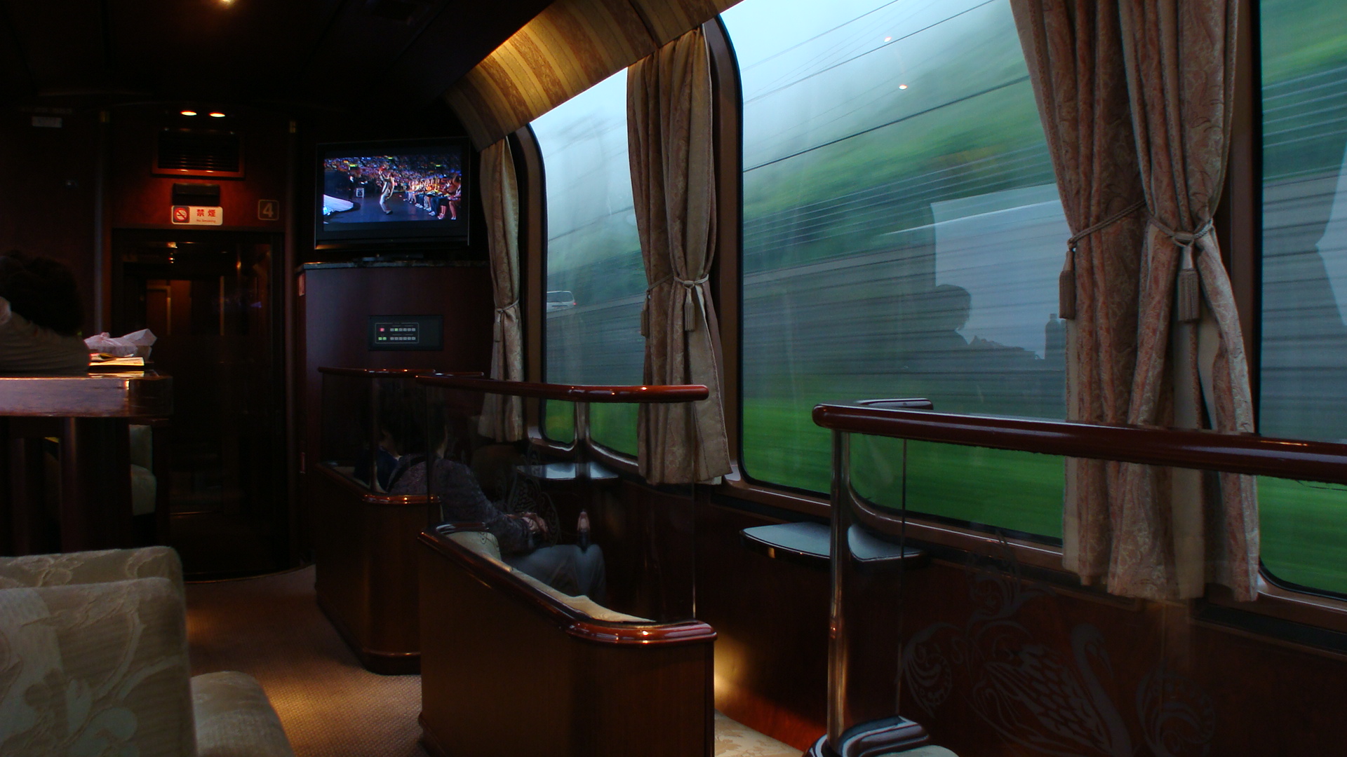
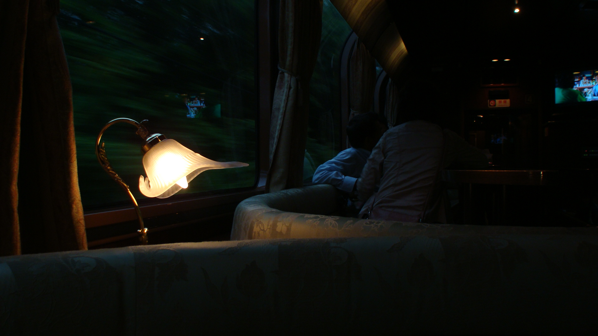
Salon Du Nord
Once settled in I decided to wander around to see what the train had to offer; The first target was the famed "Salon Du Nord". What I found was an amazing observation car beautifully fitted out with very large windows and two TVs. The channels were selectable, but of course, everyone had to agree to you changing the channel :) ... I do believe I watched the same movie 3 times whilst on my trip... but I didn't mind as I was mainly staring out the window.
The car also included the coin-shower and a vending machine. You could also go to the dining car next door and order 'from the bar'. I happened to have a very lovely couple of obaachans talk to me and ask me about my travels... it was quite difficult trying to converse in my broken Japanese and recall all the polite grammar forms; but it made the trip even more enjoyable. It made me laugh when they didn't believe that there were people from other countries taking the relaxed approach on a sleeper train because they liked trains... I was glad to change their perceptions.
Dining
I, unfortunately, did not take a full shot of the dining car, but I can assure you it is as tastefully fitted out as the rest of the train. The staff are fantastic and I even had my waiter ask where I was from and what I was up to. Then then offered drinks and the menu which had quite a lot of options. I, if I recall correctly, had a very lovely dish of Japanese Karaage (fried chicken.)
For breakfast I was greeted by the same staff and selected the Japanese breakfast option. There was no menu to choose from, as it was a set breakfast and I was asked to take a seat, admire the great view and await the meal. All of a sudden I had 5 dishes on my table and all I can say is yum!
I then bought my souvenirs; available from the dining car menu and returned to my room.
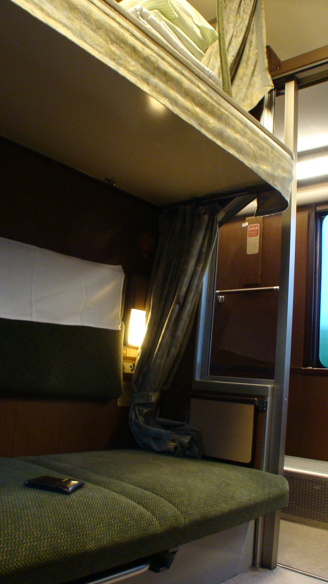
Other classes
I had chosen the 'shared' cheaper B Class sleeper rooms, but you could also have a completely private A Class sleeper room. This included a 1-seater sofa/couch which folded out into a bed. The A Class carriage also included a small communal room at one end.
Twilight Express operations
Now comes the fun part of the trip. Both trains, regardless of direction, have an engine swap half way on their journeys. Actually... I lie... over the trip the train encounters a total of 4 engine swaps, but you can't get out and watch the other 3 of them.
The engine swaps are:
- Twilight Express EF81 from Osaka to Tsuruga
- Twilight Express EF81 from Tsuruga to Aomori Depot
- Unknown (I didn't get to see it) EF from Aomori Depot to Hakodate Depot
- Double Blue DD51 from Hakodate Depot to Sapporo
The reason for the swaps are very simple. Hokkaido isn't 100% electrified, so the diesels are required. They use two for on-time running more than gradient climbing. The diesels can't enter the Seikan Tunnel (Honshu to Hokkaido) and so the unknown EF (a stainless steel version) is for that section. The EF81s are then used for the rest of the trip, mainly for brand-recognition :)
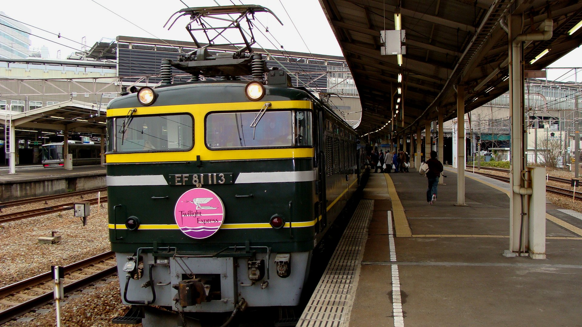
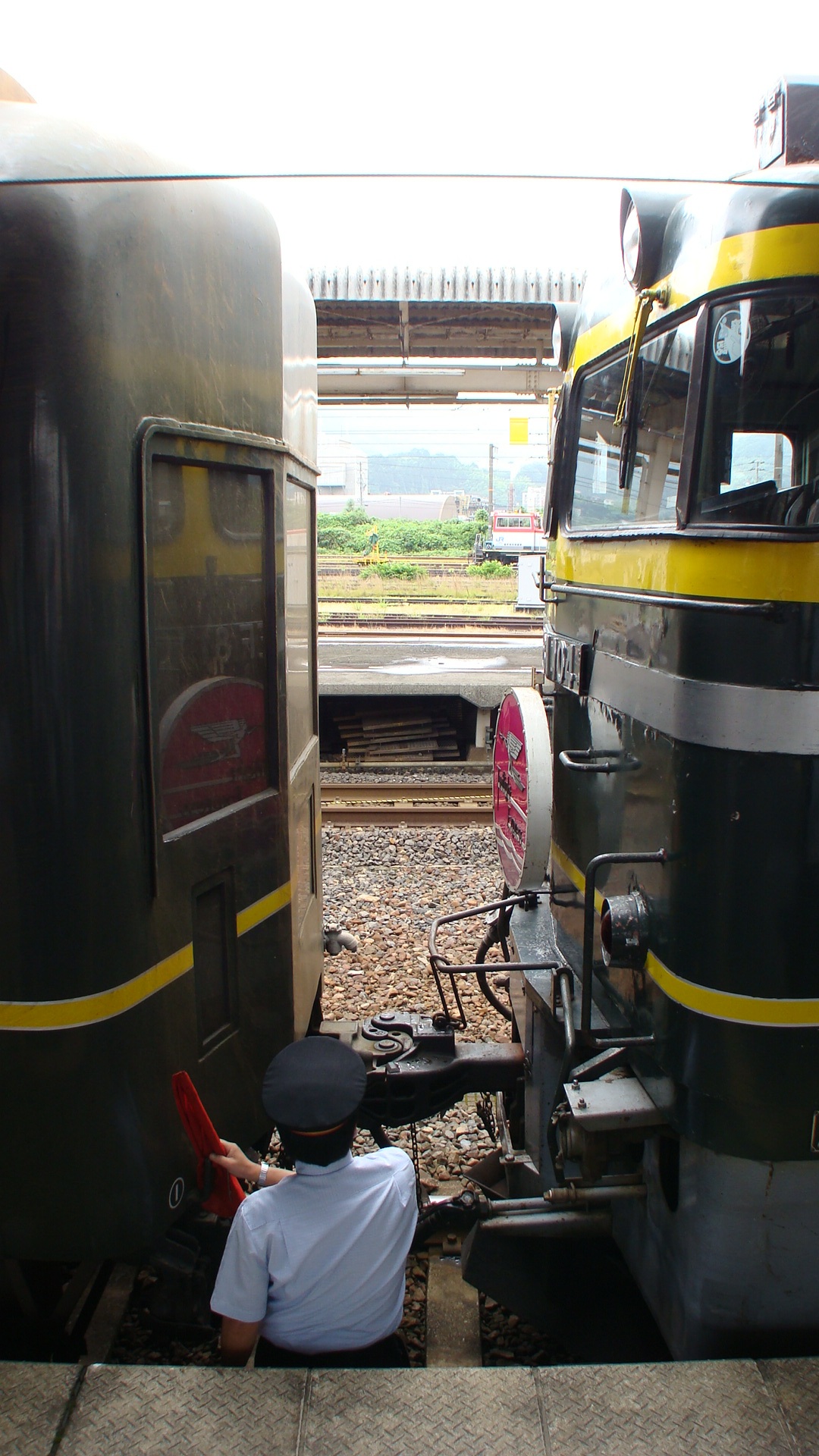
Southbound engine swap: Tsuruga
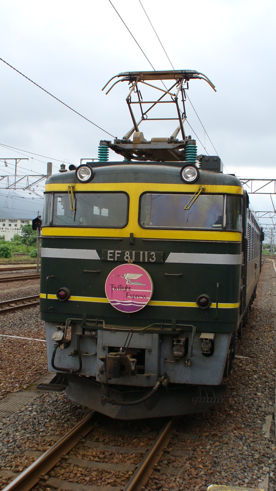
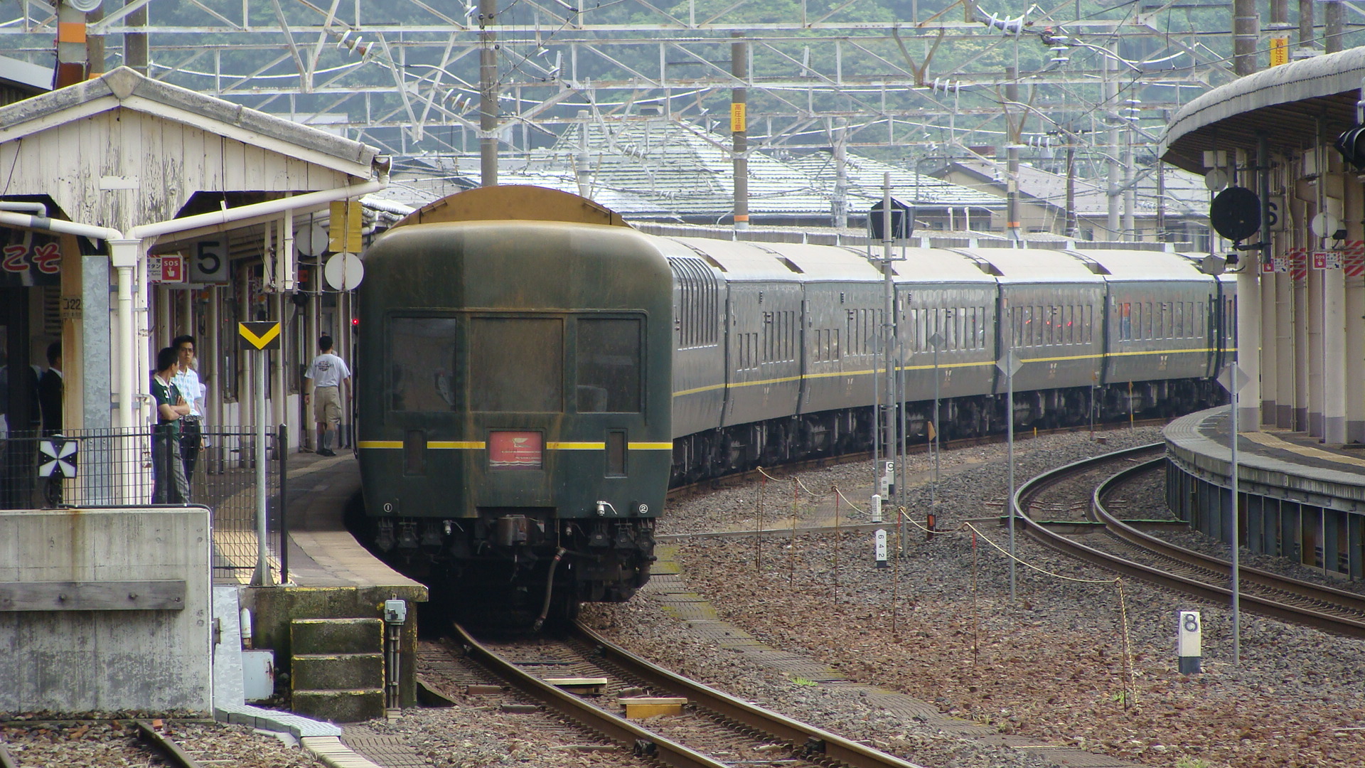
So, after a sound nights sleep, we arrived in Tsuruga with a warning that we'd have to stop over for 10minutes whilst they swapped the engines. We (as they pretty much expected we were all train fanatics) were allowed out to take photos but were to return to the train as soon as the buzzer was heard.
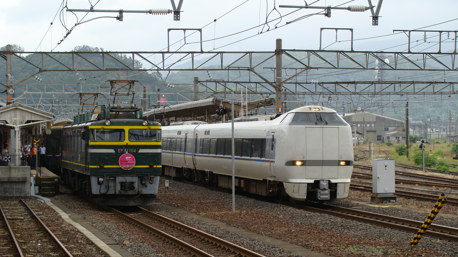
Who could resist? I got out of the train and got to the front to see our first engine (EF81 113) already detached and heading south to the depot. I then walked further down the platform to take a shot of our train next to the Thunderbird that had just arrived. I could not believe the dirtiness of our consist; I hadn't expected an EF81 to cause that much build-up on the passenger car, but it could have been caused from the entire trip.
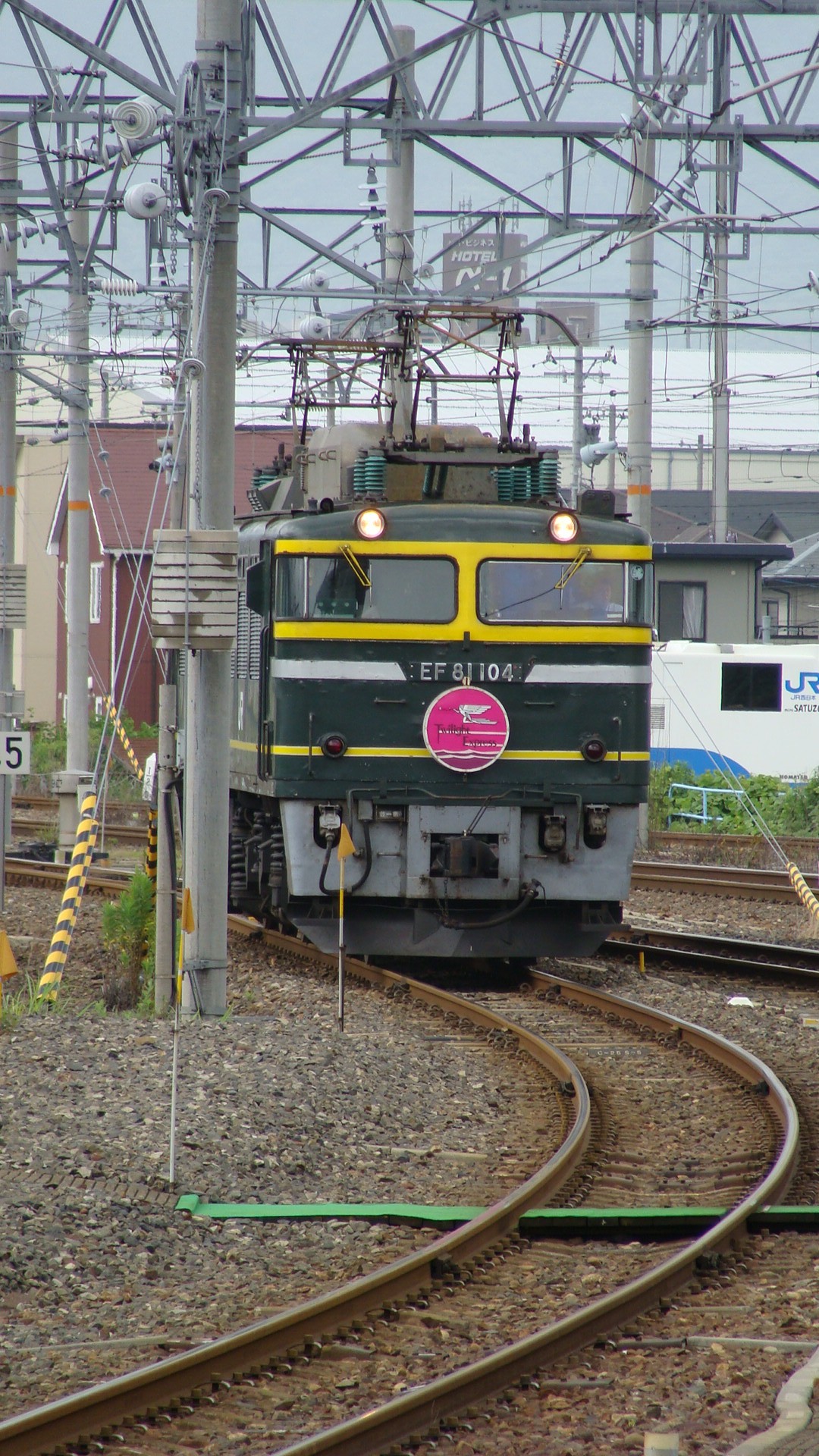
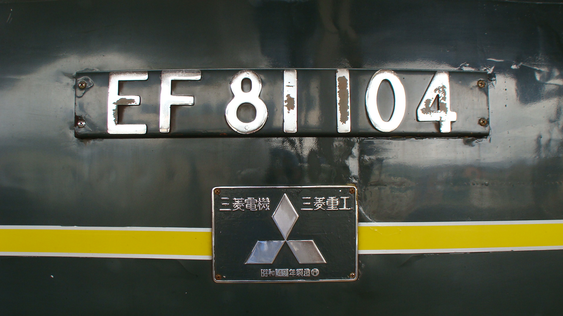
EF81 104 then started approaching to couple up to the train. It had been sitting in the yard ready to come up as soon as 113 had cleared the points. As soon as it 'clunked' onto the train and the air flowed the buzzer on the platform went off and everyone cleared back on to the train.
Final stations to Osaka
As we got closer and closer, more and more passengers departed at certain platforms. The train was actually scheduled to only stop at stations that passengers had designated to get off at; which is now quite obvious, as it was never going to pick any up. I had booked all the way through to Osaka, but was considering getting off at Kyoto... Unfortunately we were held up due to 'unfortuante circumstances' and I ended up just relaxing in the Salon Du Nord and getting back to Osaka an hour late.
Since this trip I've now also travelled on the Hokutosei and the Kitaguni. I still recall the Twilight Express as being the most memorable and stylish... but will endeavour next to get onto the Cassiopeia.
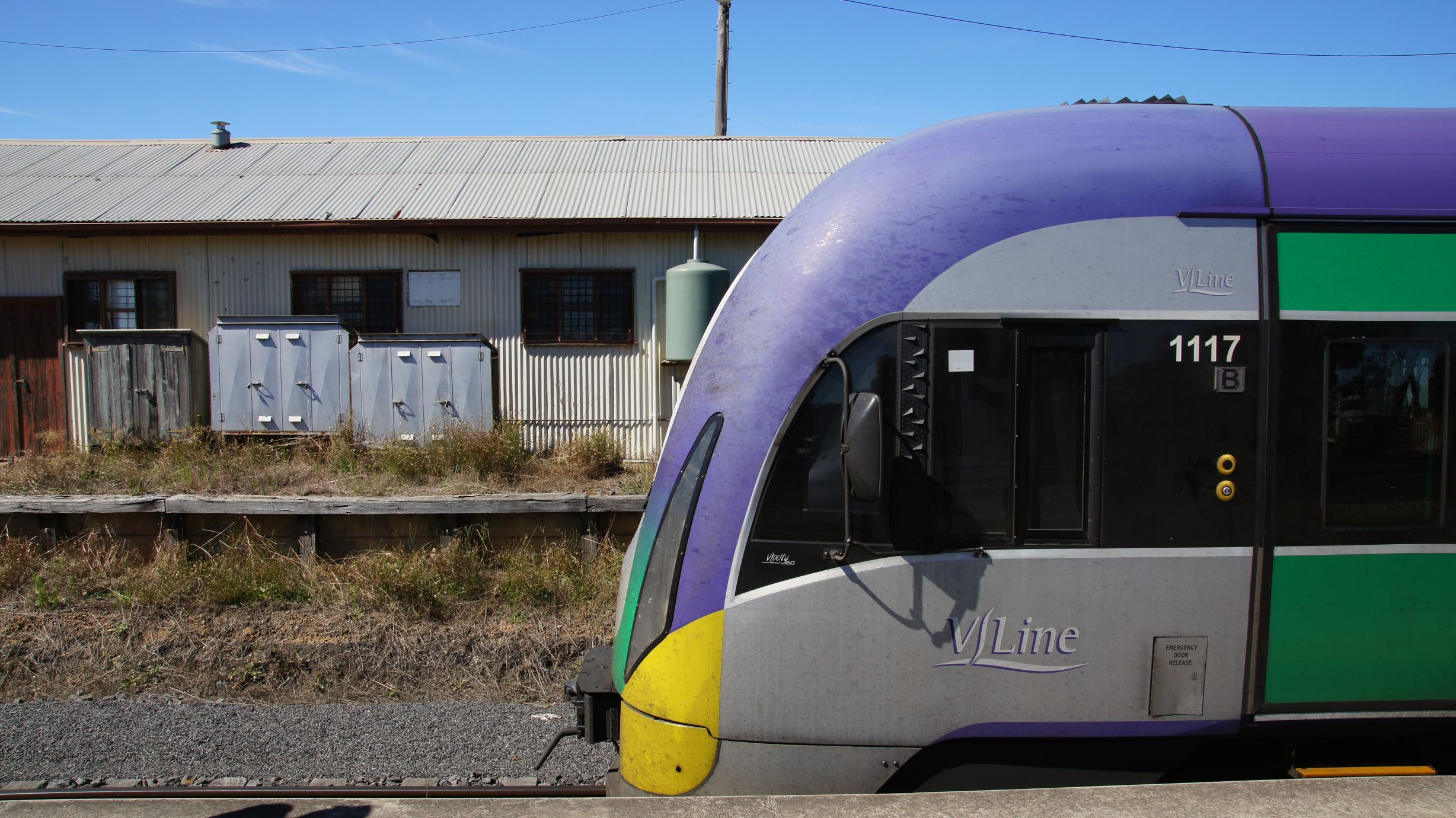
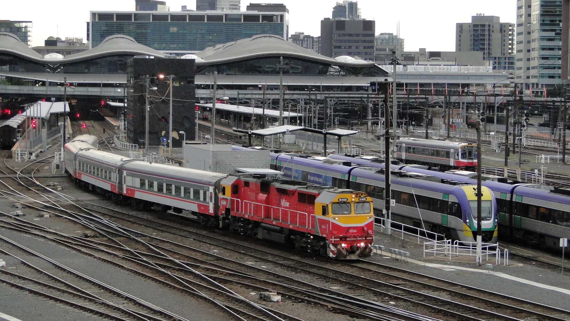
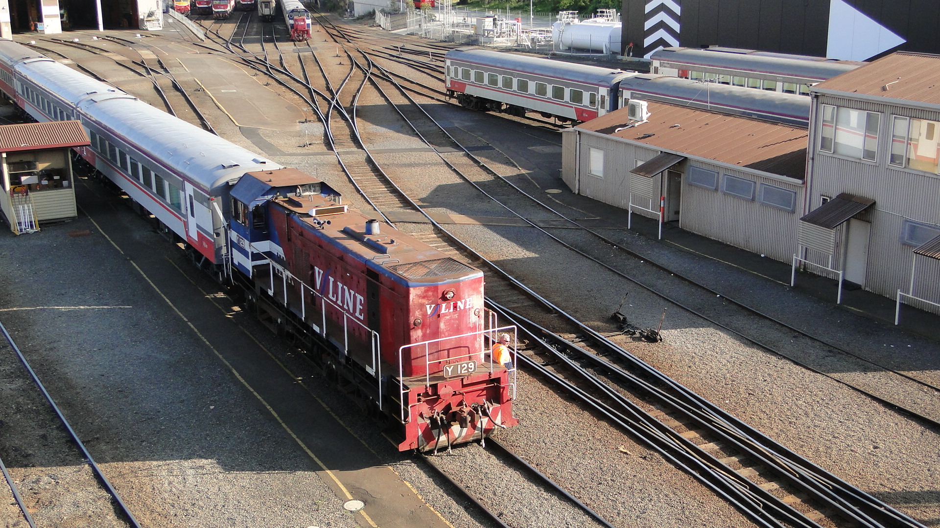
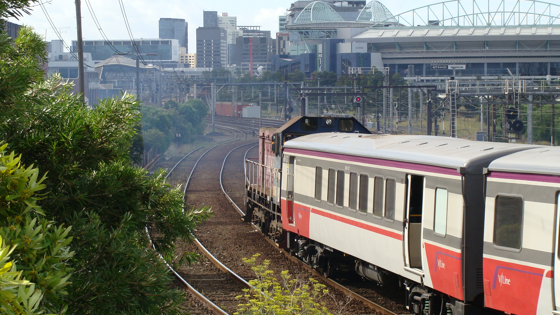
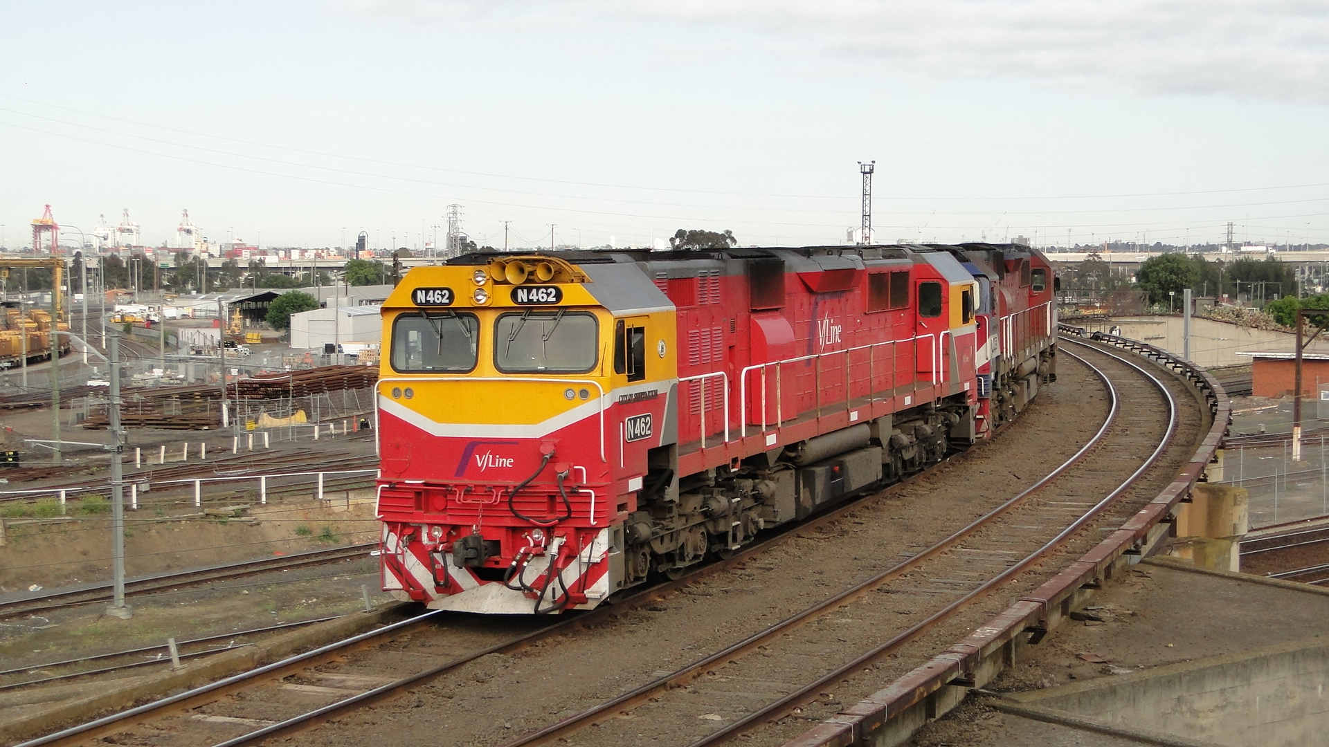
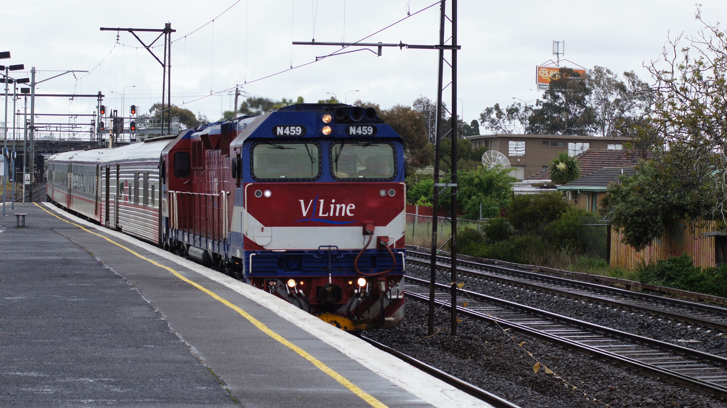
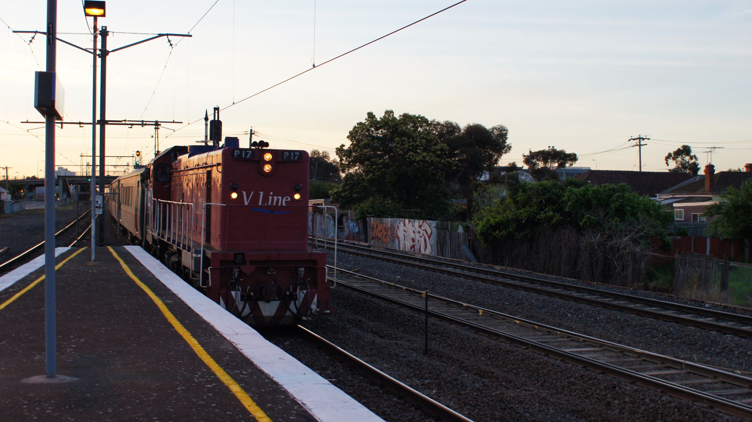
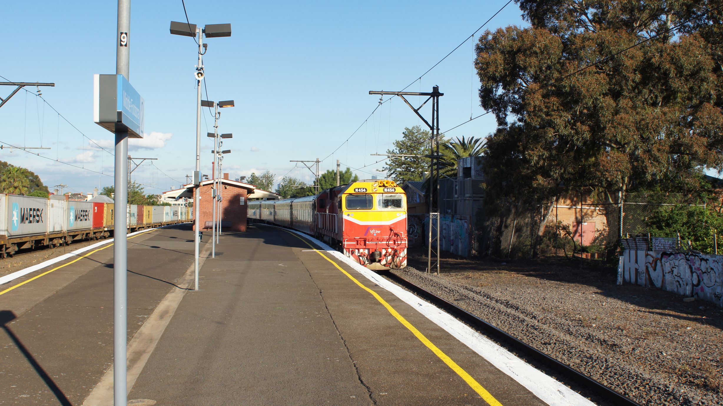
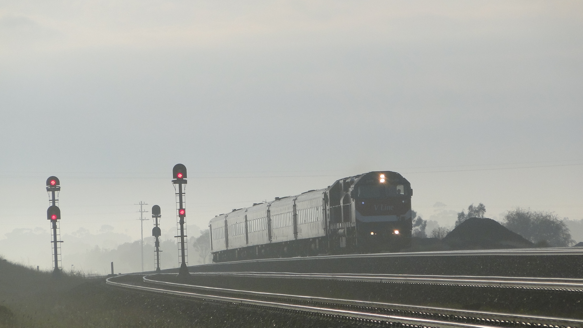
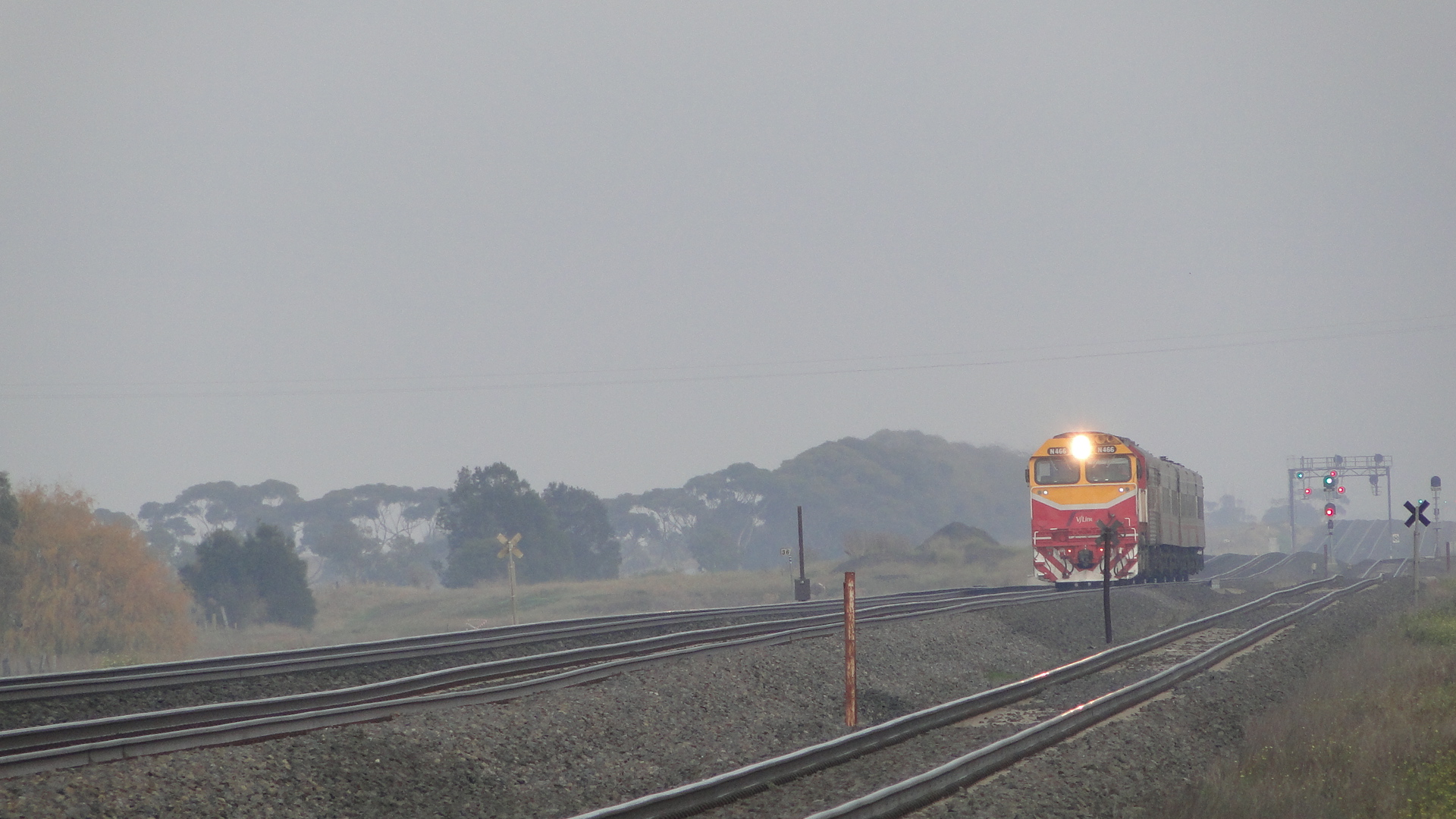
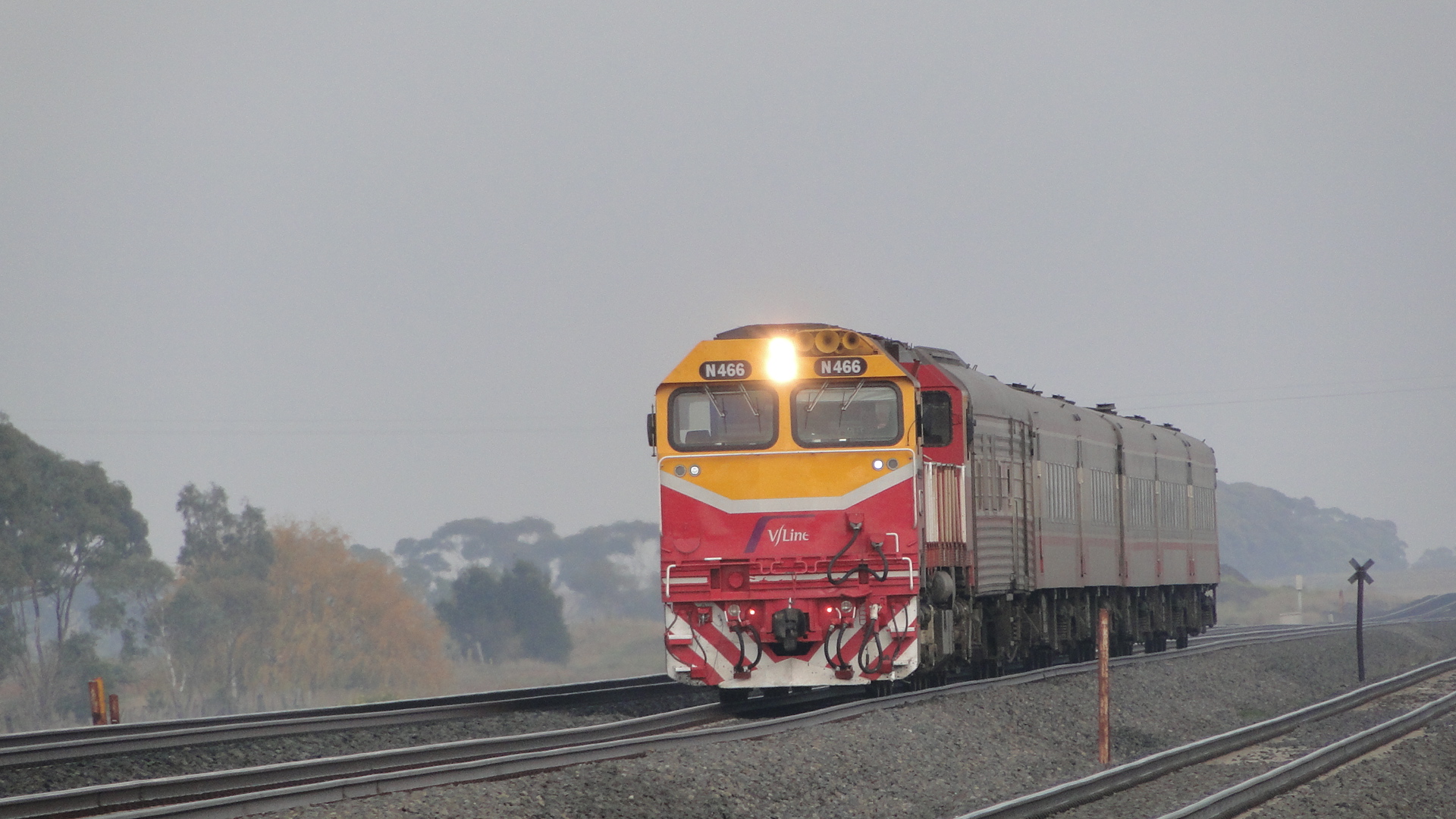
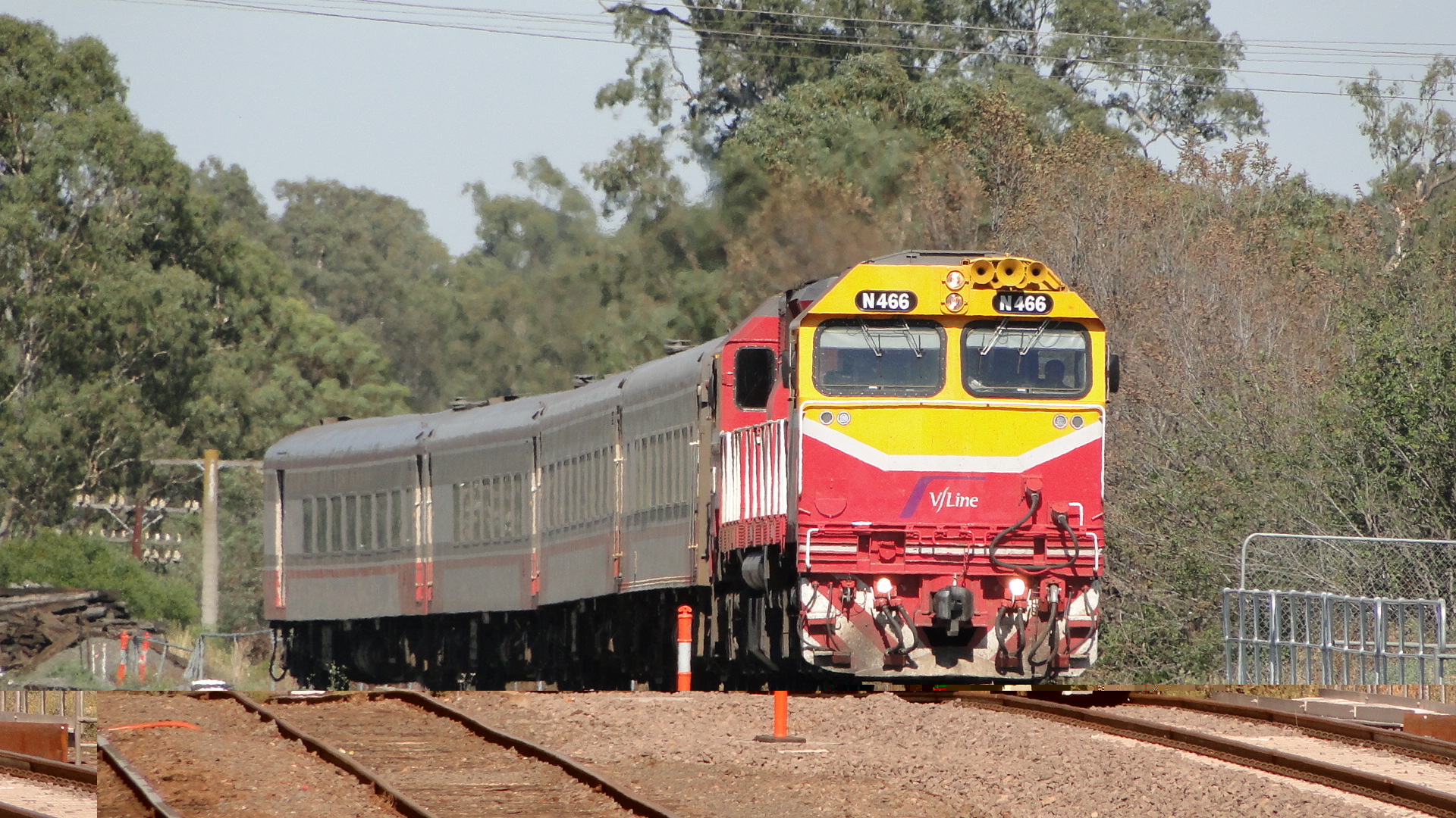
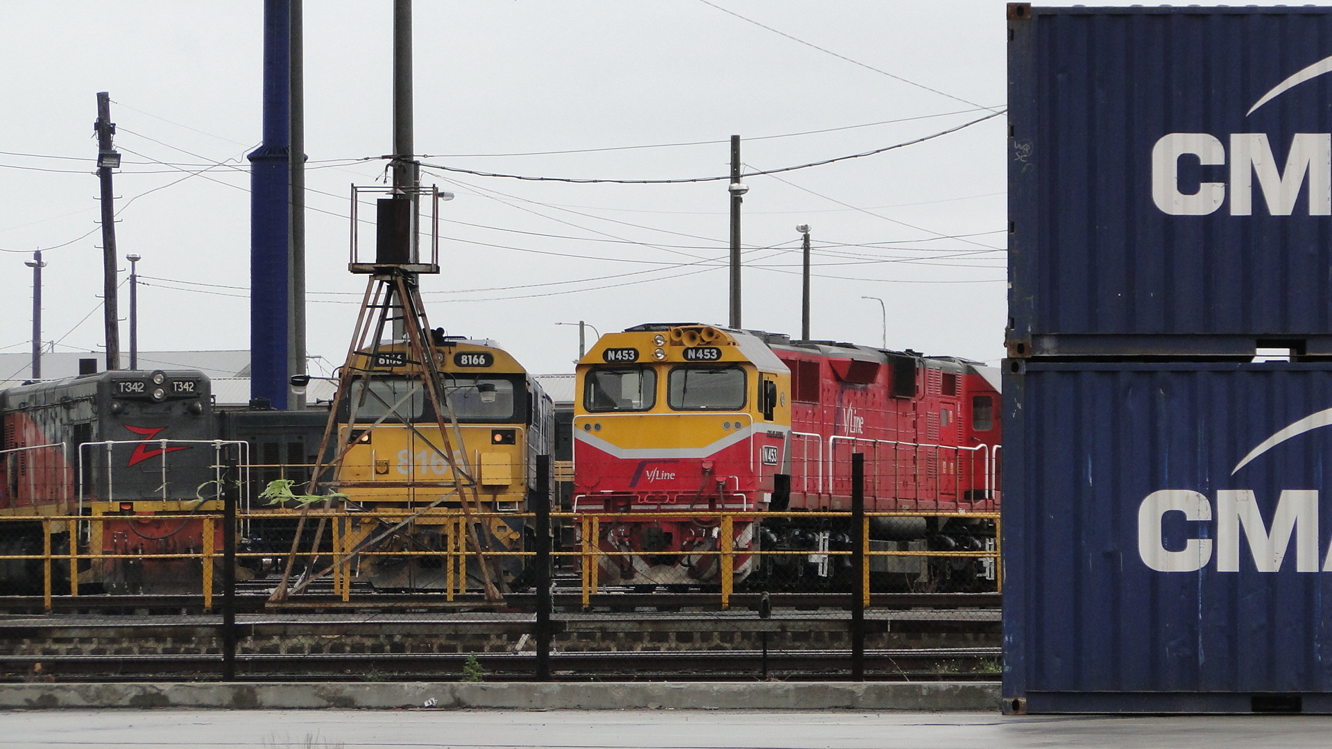
V/Line Rolling Stock
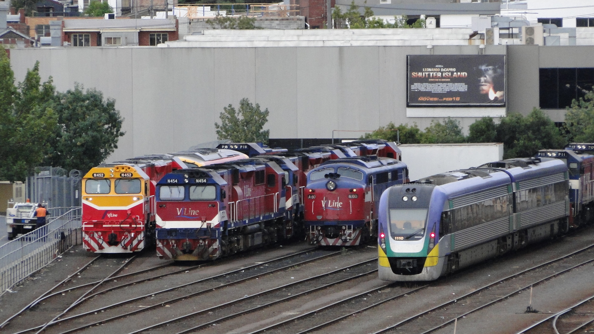
I've now realised how many photos I'm burying in the depths of my Photo Album (specifically the Australian Railways Album) and so I'm going to throw a few sets together and post them here as I find the time.
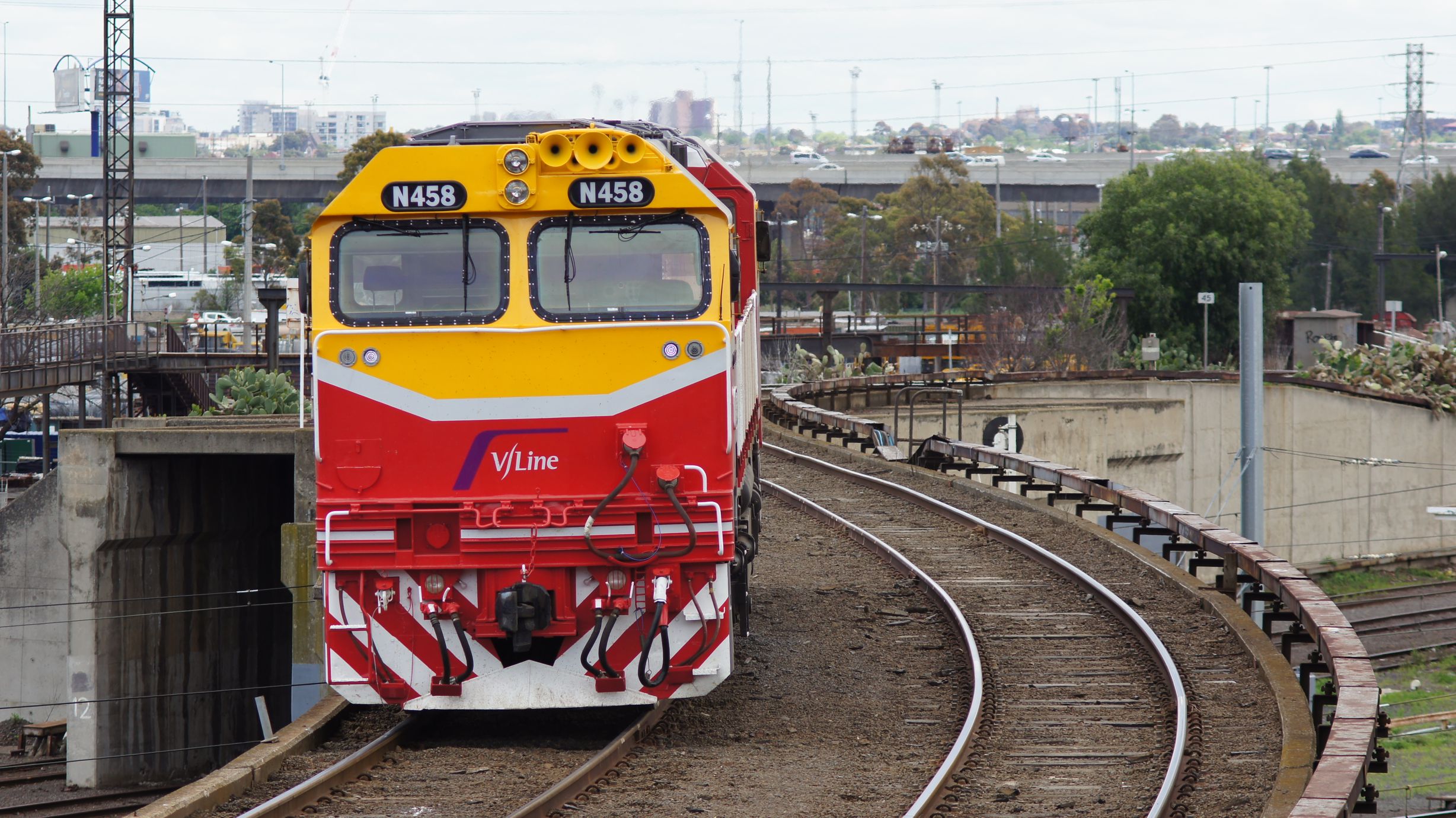
First out of the yard is a collection of V/Line Stock. V/Line are currently repainting a lot of their diesel locomotives (and their V/Locity DMUs) in 'Hi-Vis' colour-schemes; somewhat reminiscent of the 'Candy' scheme I missed out on due to my age :)
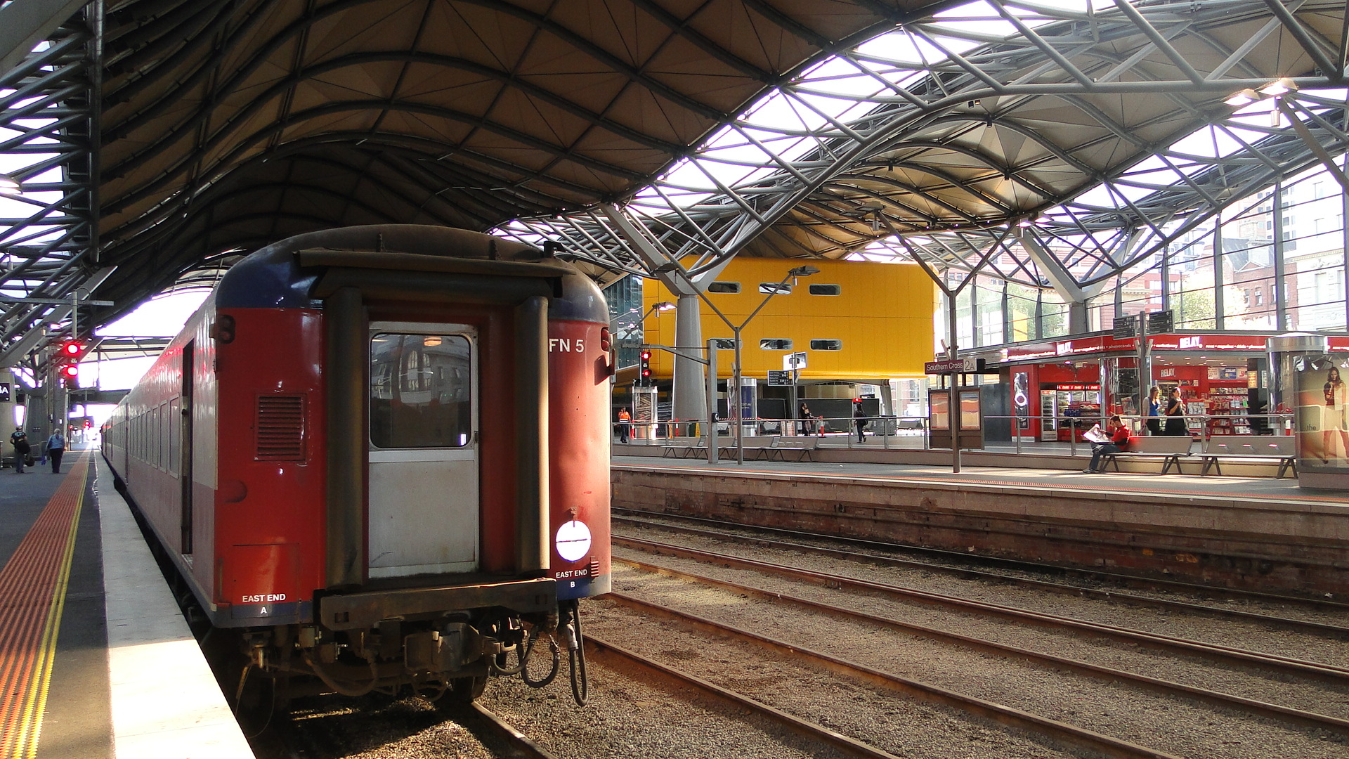
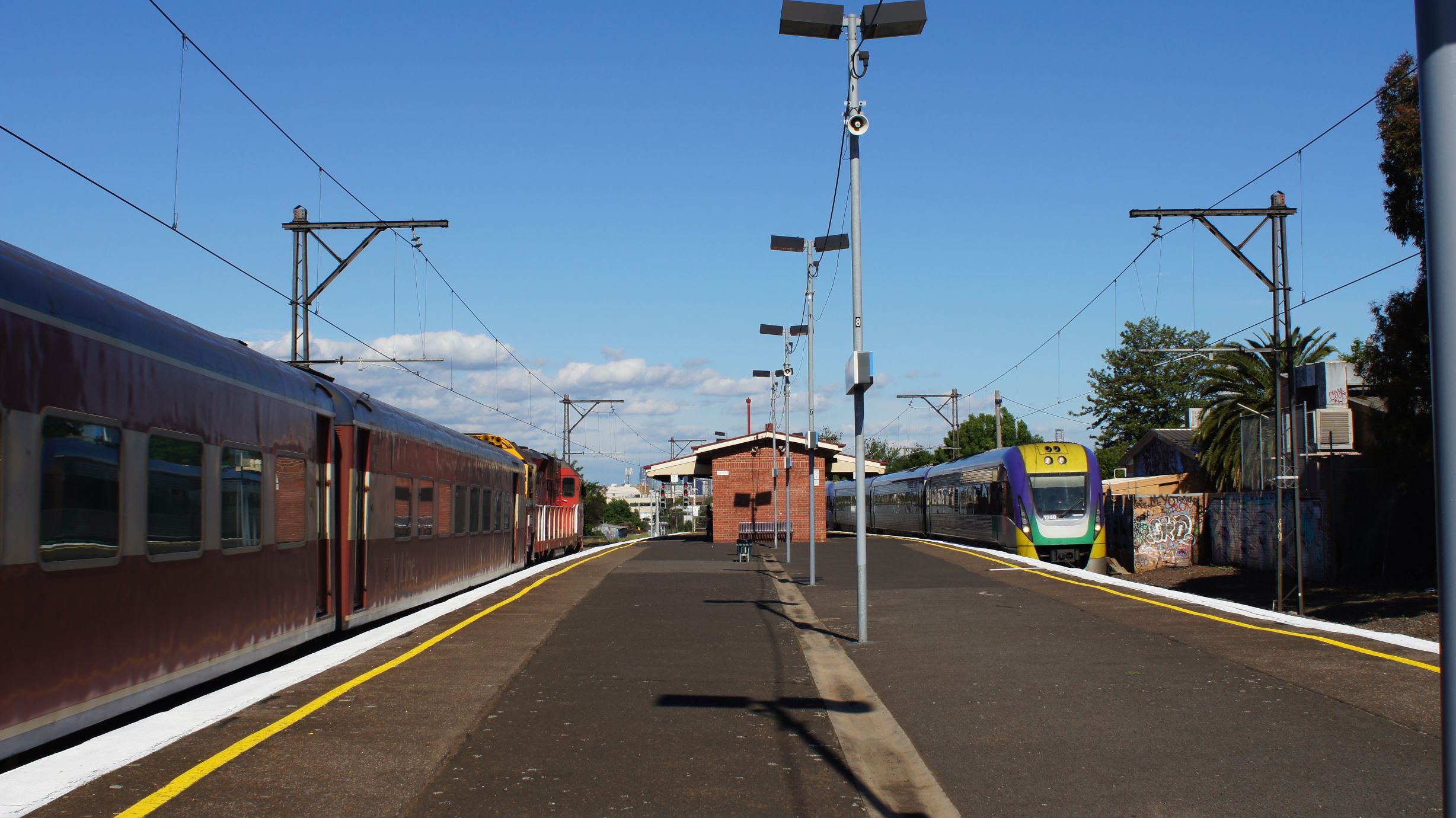
Shots from around Southern Cross Station
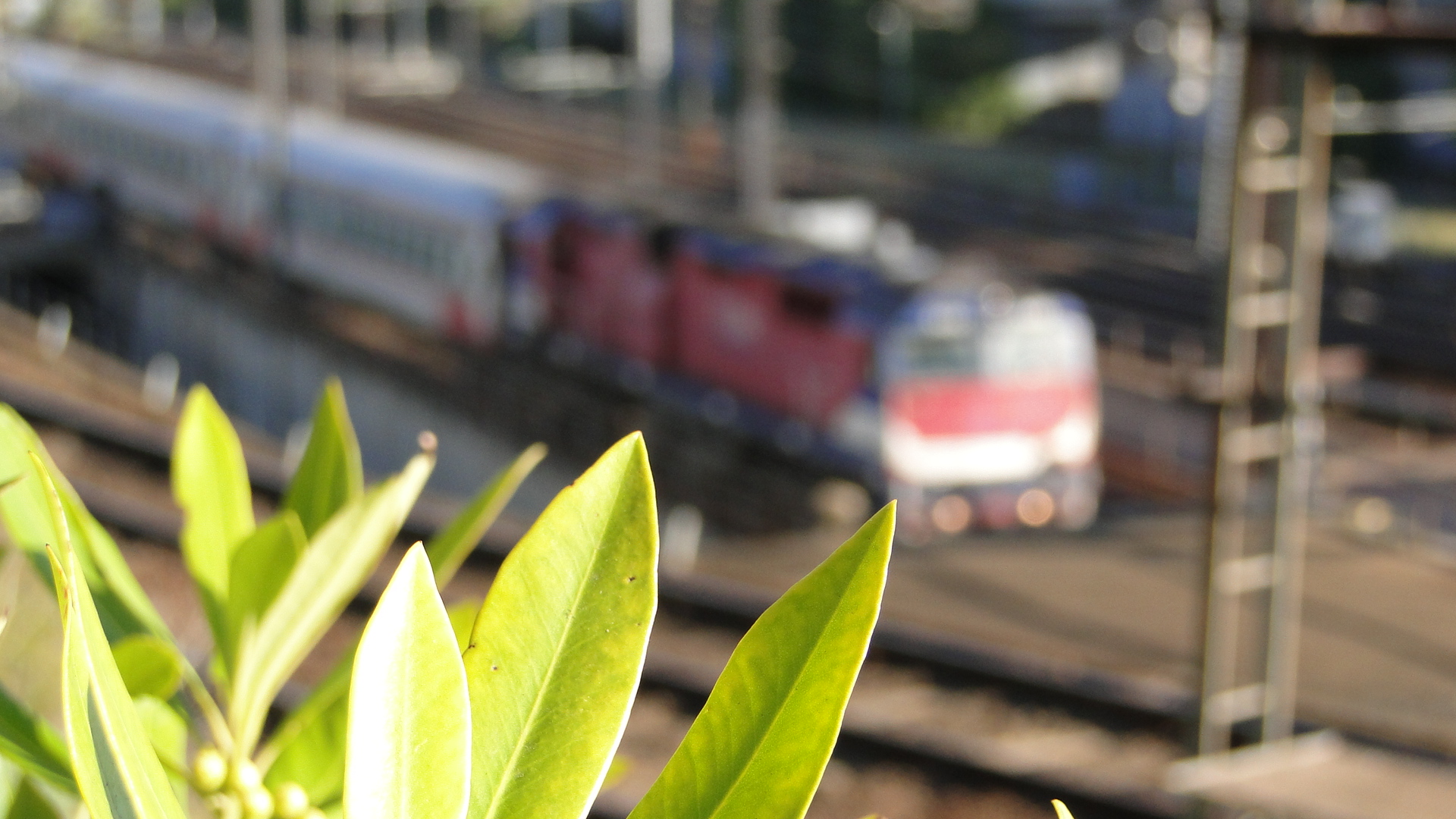

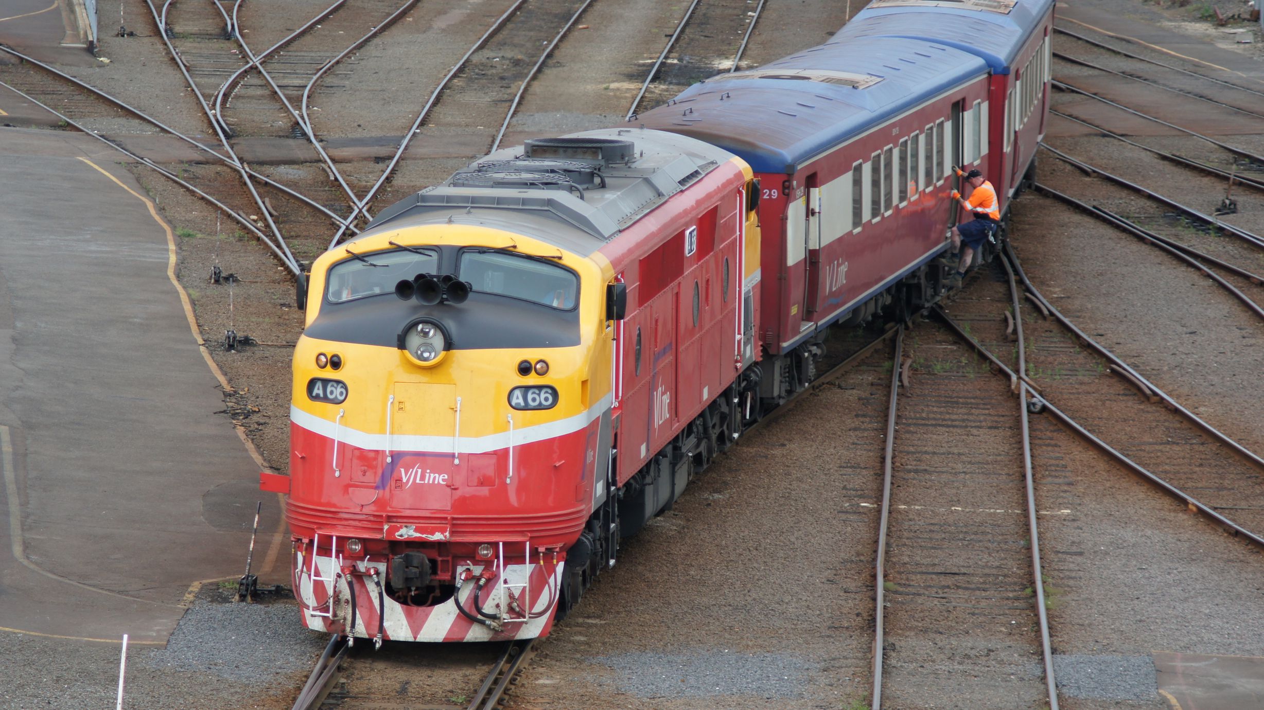
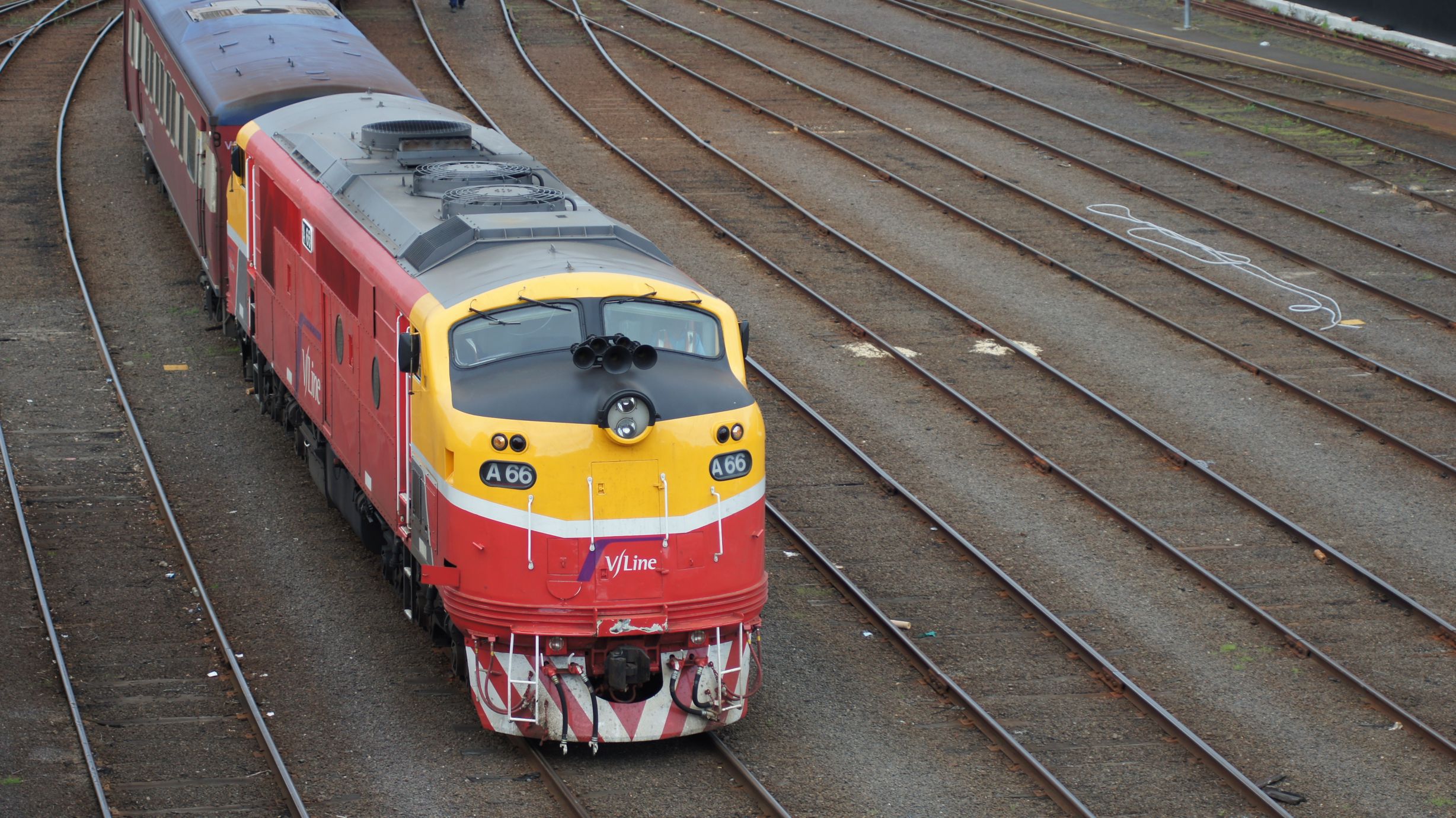
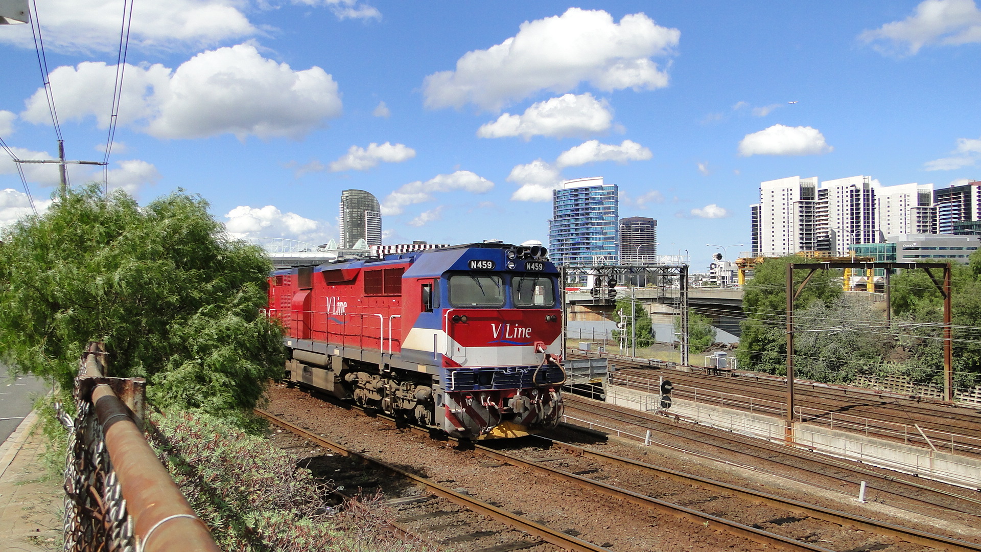
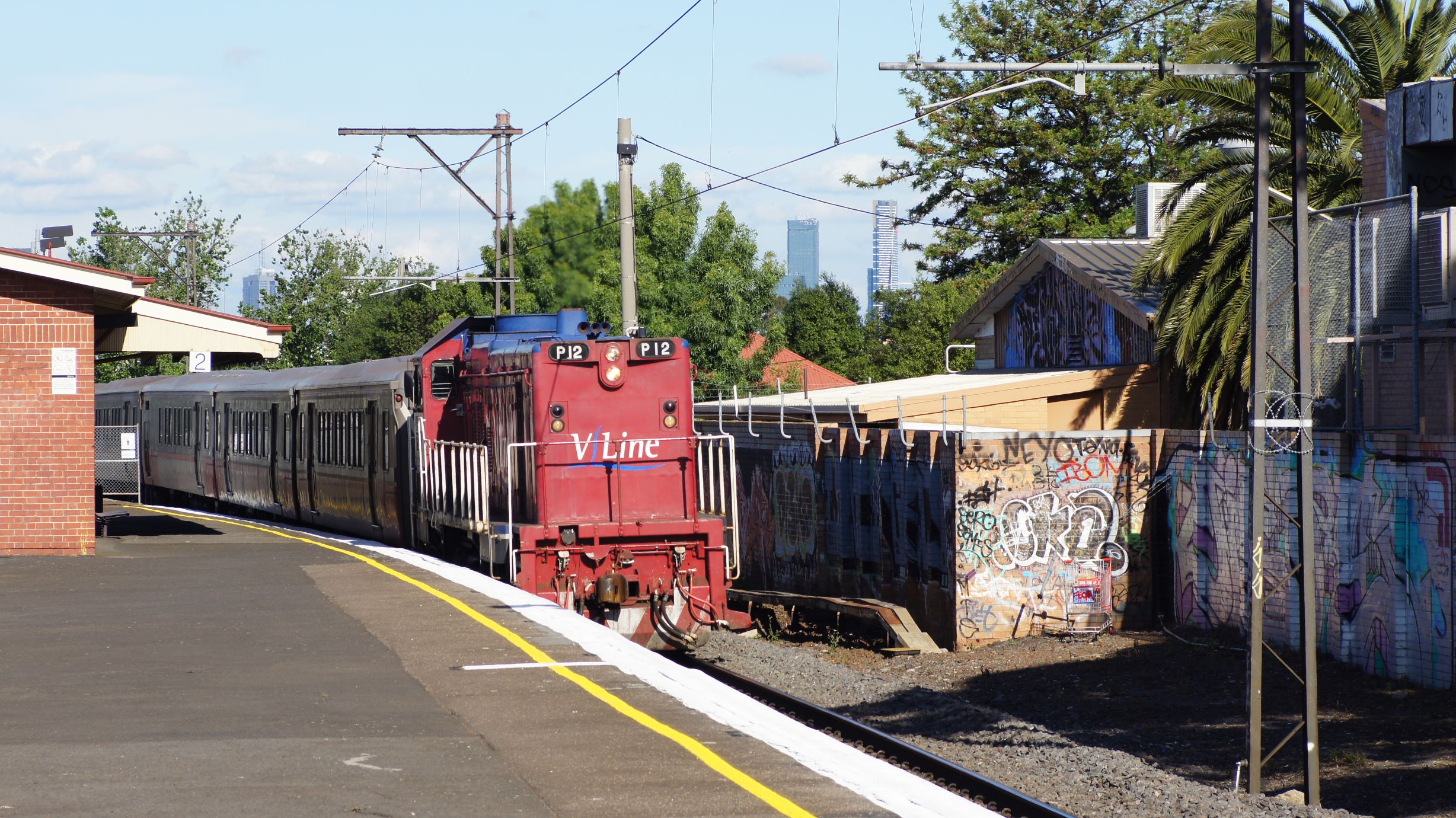
V/Line on the flyover near North Melbourne Station
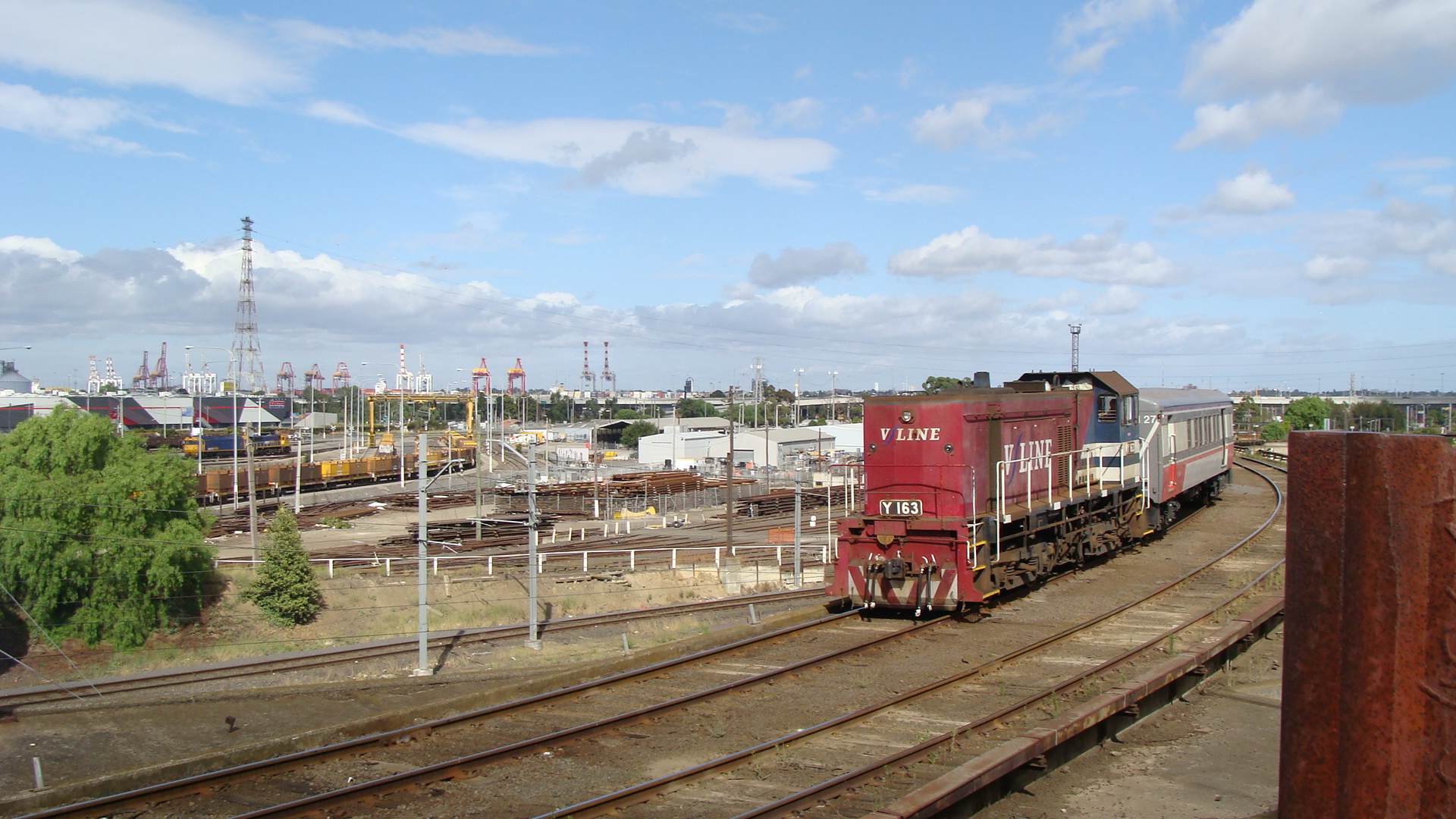
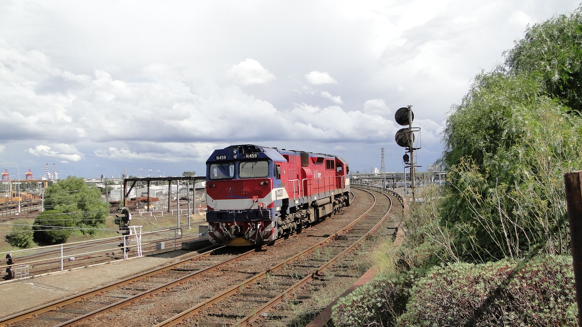
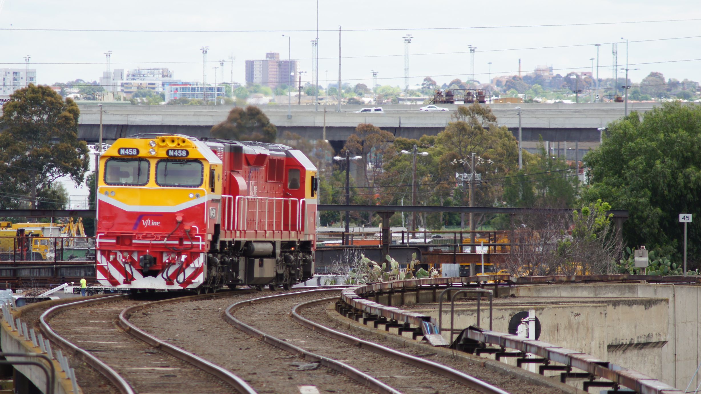
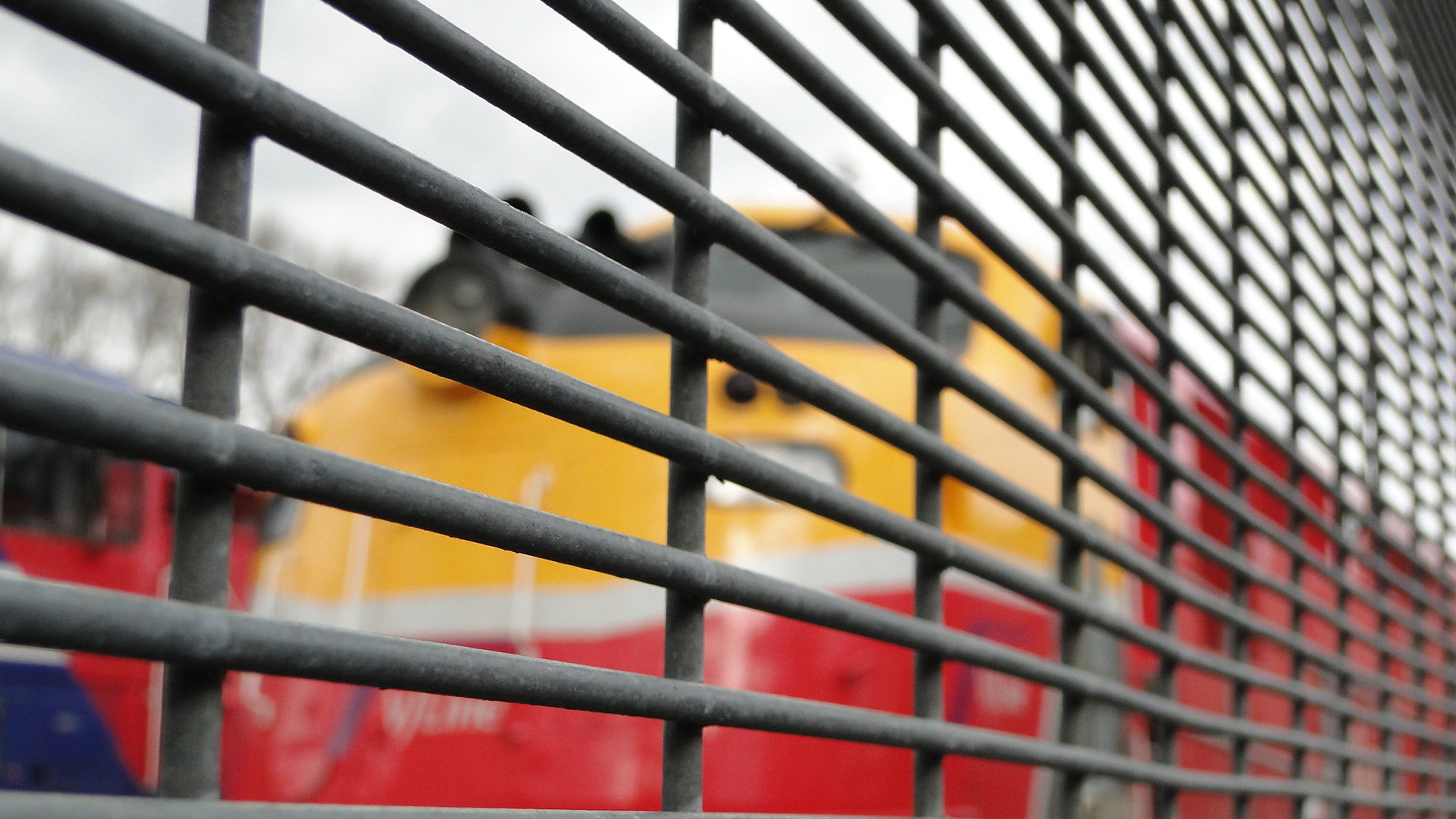
Passing Middle Footscray
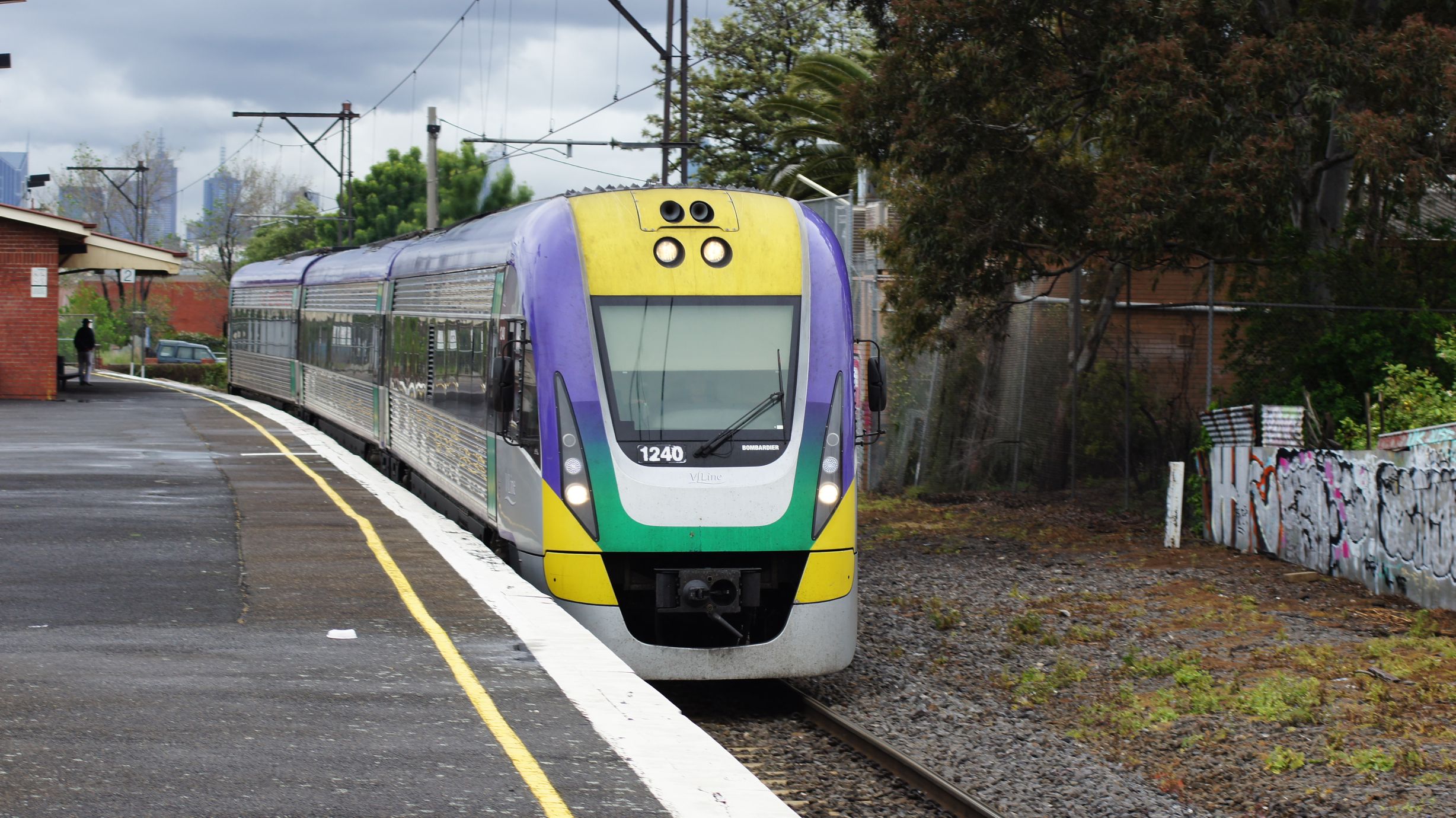
Passing Manor Loop
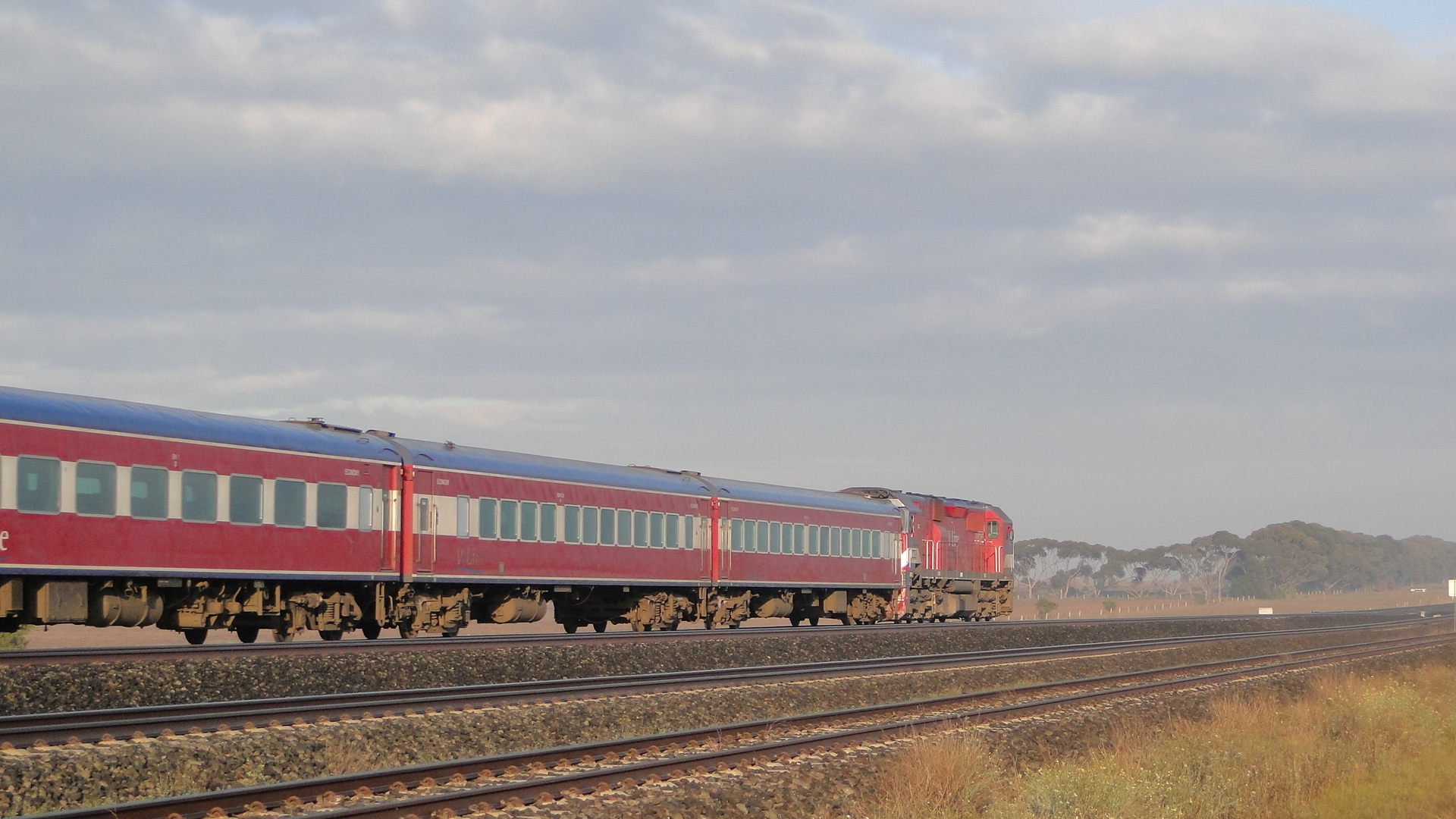
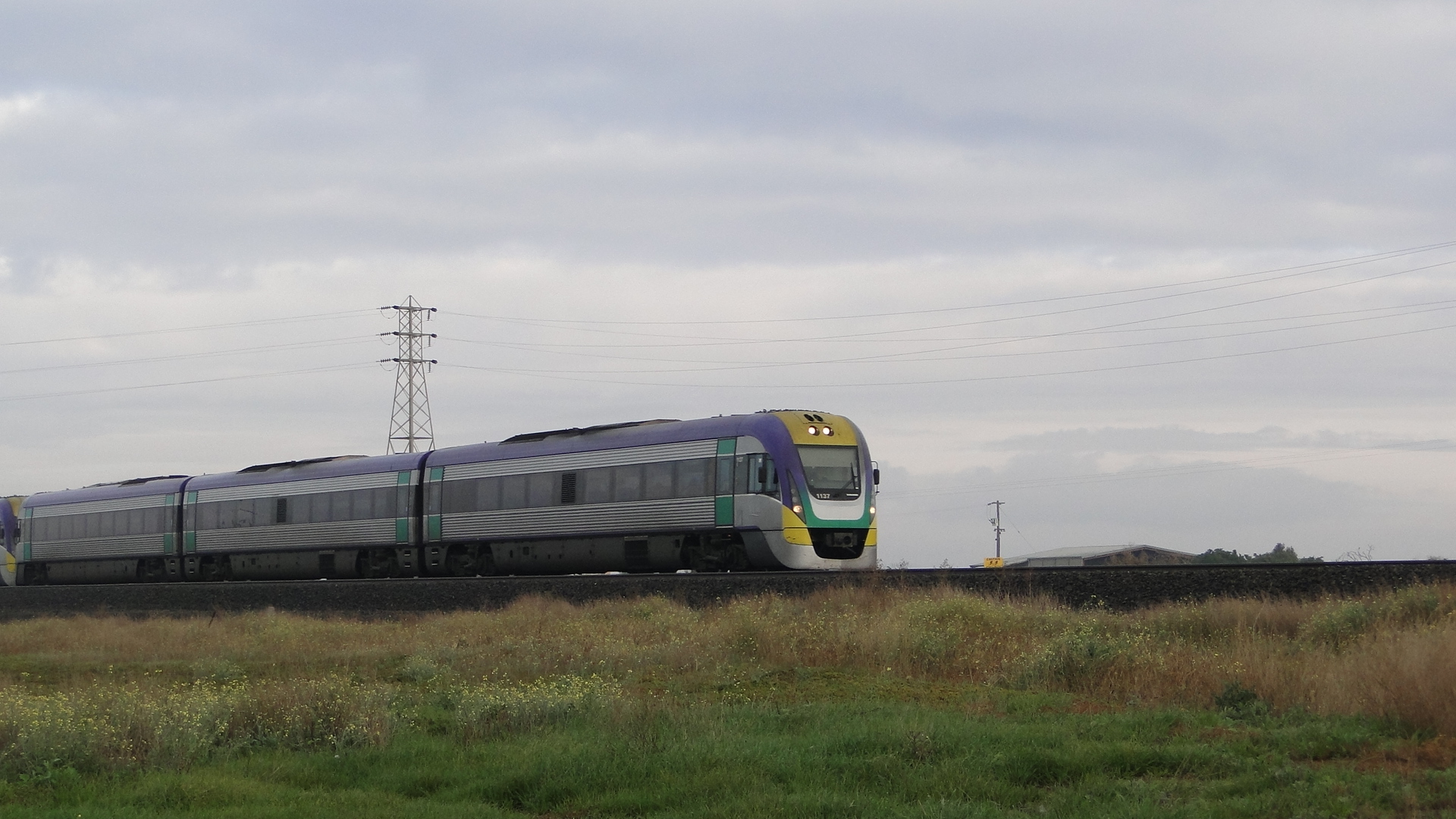
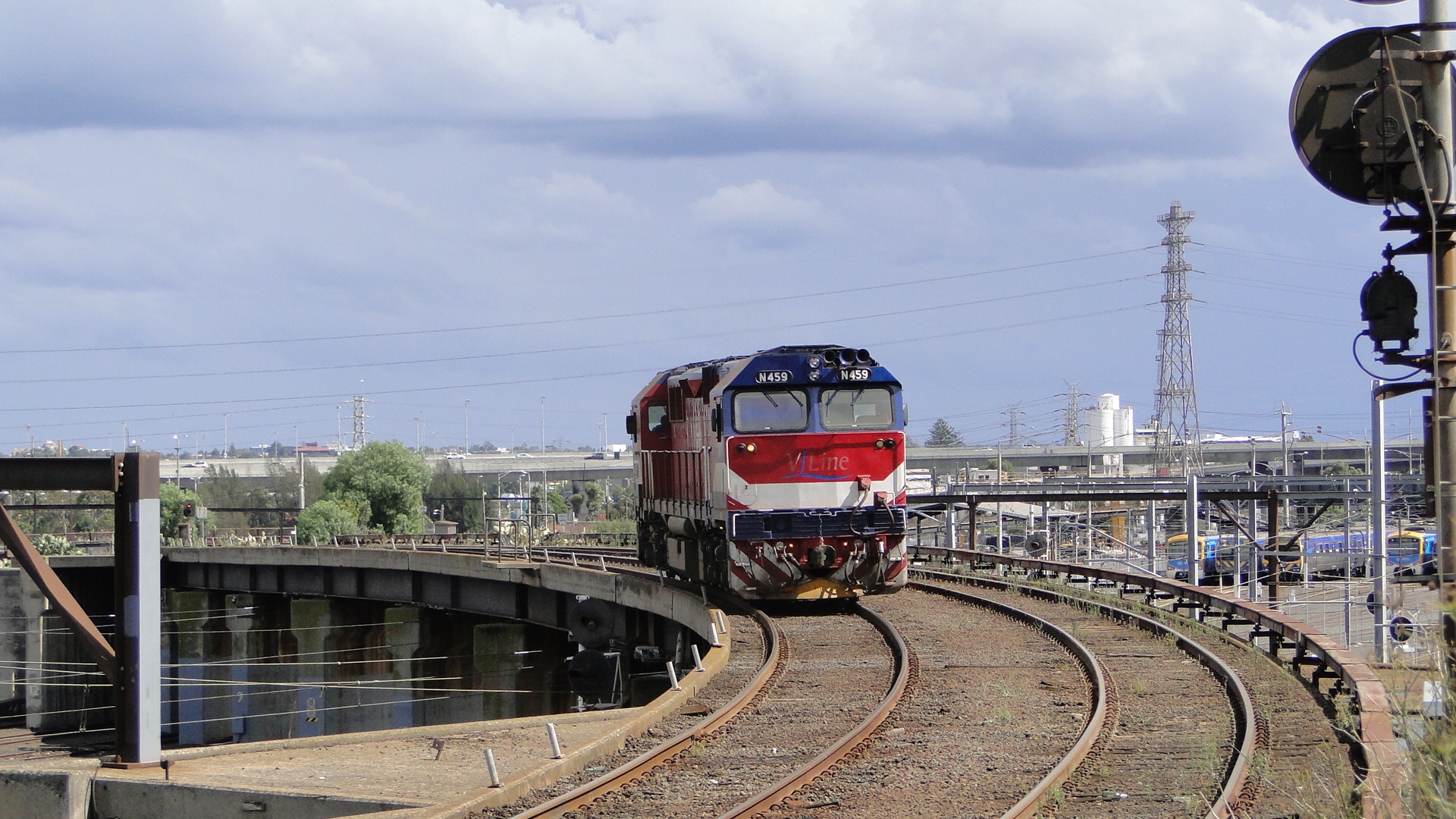
And other locations...

Random Photos
Search
Tags
Links - Click for details
- Abandoned Rails (Japan)
- AIRLINE (Shinkansen Photography)
- Akihabara Station
- annexpressのブログ
- Australian Model Railway Magazine
- DCC普及協会ホームページ (Japanese DCC)
- Dead Section (Japanese Track Diagrams)
- Delicious Things (Japanese N Scale DCC)
- Densha Wotorou
- Digital Direct for Windows (DCC Server)
- Don's Dream World – AMAZING N Scale Japanese Layout
- Hatena::Diary
- Japanese N-Scale Modeling Forum
- JR Chiisai
- Kaz-T's blog レインボーライン (Rainbow Line)
- LED Resitance Calculator
- Masioka
- Poppondetta Blog
- RailFan Magazine, Japan
- Railmind
- Railway Travelers' Room
- Serenity Valley
- Shashinka Ichiban
- Shuzuku
- Sumida Crossing
- The next station is…
- Tomix N Gauge Track and Japanese N Gauge Trains
- TT Forums (Transport Tycoon Deluxe)
- 名鉄尾西線の貨物列車 (Nagoya: Meitetsu Freight)
- 日本型Nゲージ DCC改造例のご紹介 (Okiraku DCC)
- 泰 茅 轍 道 (Taichi Railway)
- 箱庭登山鉄道製作記 (Hakone-Tozan Layout Blog)
Archive
- July 2026
- May 2026
- April 2026
- March 2026
- February 2026
- January 2026
- November 2025
- October 2025
- September 2025
- August 2025
- July 2025
- June 2025
- February 2025
- January 2025
- November 2024
- September 2024
- August 2024
- July 2024
- June 2024
- May 2024
- April 2024
- March 2024
- February 2024
- December 2023
- October 2023
- September 2023
- August 2023
- July 2023
- June 2023
- May 2023
- April 2023
- March 2023
- December 2022
- November 2022
- October 2022
- April 2022
- March 2022
- February 2022
- January 2022
- December 2021
- November 2021
- September 2021
- August 2021
- July 2021
- May 2021
- March 2021
- February 2021
- January 2021
- October 2020
- September 2020
- August 2020
- July 2020
- June 2020
- May 2020
- April 2020
- March 2020
- January 2020
- December 2019
- November 2019
- October 2019
- September 2019
- August 2019
- July 2019
- June 2019
- April 2019
- March 2019
- February 2019
- January 2019
- December 2018
- November 2018
- October 2018
- September 2018
- August 2018
- July 2018
- June 2018
- May 2018
- April 2018
- March 2018
- January 2018
- December 2017
- November 2017
- October 2017
- September 2017
- August 2017
- July 2017
- June 2017
- May 2017
- March 2017
- February 2017
- January 2017
- December 2016
- November 2016
- October 2016
- September 2016
- August 2016
- July 2016
- June 2016
- May 2016
- February 2016
- November 2015
- October 2015
- September 2015
- August 2015
- July 2015
- June 2015
- May 2015
- April 2015
- March 2015
- February 2015
- January 2015
- December 2014
- November 2014
- August 2014
- July 2014
- May 2014
- April 2014
- March 2014
- December 2013
- November 2013
- October 2013
- June 2013
- August 2012
- April 2012
- March 2012
- February 2012
- November 2011
- October 2011
- September 2011
- July 2011
- June 2011
- May 2011
- April 2011
- March 2011
- February 2011
- January 2011
- December 2010
- November 2010
- October 2010
- September 2010
- August 2010
- June 2010
- May 2010
- April 2010
- March 2010
- February 2010
- January 2010
- December 2009
- November 2009
- October 2009
- August 2009
- January 2009
- December 2008
- November 2008
- October 2008
- September 2008
- July 2008