


 Melbourne BG SCS Train Timetable


Paris, January 2015
So, the goal was to see the TGV La Poste. I'd also been warned.. it'd be dark. Well, it was. Pitch-black. I got to Maisons Alfort-Alfortville early on two mornings and saw the TGV La Poste (two, on one morning) pass. It was too dark to get a shot with the equipment I had. Another morning, I hung around the east end of the Gare De Lyon yards. The result is as follows.
That, my friends, is the TGV La Poste. I then proceeded to scale the yard on foot, trying to find where the train stopped. It was nowhere to be seen... I have no idea what shed it rolled in to, but it is not visible from any bridge, road or platform.
The land of the TGV
I had seriously underestimated the sheer quantity of TGV rollingstock in France. The variety, too, was much grander than I had expected. My first model train was a Lima HO TGV in orange and grey and it was good to see that this model was still running... although somewhat refurbished.
Anyway, whilst scaling the yards for the yellow one... I took photos to make sure that my entire trip wasn't going to end in a puddle of tears.
..next time it'll be summer... it'll be southern France... it'll be at the beach ... and the TGV La Poste will have been discontinued and chopped up.
Zurich, January 2015
Zurich: 1, Steven: 0. There's a standard rule for train photography: The train will come as soon as you choose to leave.
The town
Zurich is like a European version of Japan. I could not believe how prim, proper and perfect the town was. Immaculate cars, buildings, people... Everyone seemed to smell 'foreigner' on me... It occurred to me later that I was the only one with facial hair (unkempt at best) in the whole town.
I'd always wanted to visit this country... not for The Sound of Music, but for the railways. I'd heard the standard saying that you could set your Swiss watch to them. I also have a Mondaine watch which is built on the design of the Swiss Railways clock (of course, the same design that Apple 'accidentally' borrowed!)
Chasing Trains
I'd been researching prior and understood that there was a main yard to the west of the main HBF and that some freight ran south to the west of Lake Zurich. This traffic joined the line somewhere near Thalwil and I'd found great shots online around the area.
So... As that I was there two days, I'd decided to scout the first day and tackle the trains on the second (in amongst urban-exploring, shopping, eating, etc...)
The first day I made it to Thalwil (the railway ticketing system is really easy) via Tram and Train and started wandering around. Within 10 minutes the police were already chasing me and asking what I was doing. It was a bit tense as I'd left my Passport in the hotel and had wiped my camera of my previous London photos. Either way they phoned the HQ and believed my story. I don't quite know how they verified my identity from my drivers licence.
A freight train was parked in Thalwil yard the moment I got there... bonus. It then left south. After Starbucks and a little more wandering I'd decided that the best bet would be to go to the next south station the next day.
Day two: Oberriedden
The morning started pretty bleak at Thalwil... I'd jumped on the next train south which happened to be an express that would skip Oberrieden, so I had to transfer. No problems, but I kept a low profile to not entertain the police again.
Oberrieden is a two platform station with a dual-track line running through. It seems a lot of commuter traffic and a tiny bit of freight. There's a great curve to the north to catch south-bound traffic all day...
That last shot is the Austrian OBB Railjet.
There was a lot waiting at the station and a lot of the passenger traffic. In fact, out of the 2-3 hours spent, two freights passed, and they both passed to the north.
They both had the cutest little (old?) electric engines on the front... very well maintained also as they were stealth. It was getting on to home time, so I'd decided to head back to Thalwil to transfer to an express back to the hotel. Just my luck... as I approached Thalwil there was a freighter with a string of open hoppers waiting for us to clear the southbound junction.
...Why...couldn't....I....have...waited...10...more....minutes!?!?! Either way, back at Thalwil a light-engine movement bolted past me.
Zurich main yard
This area probably has a proper name, but I haven't researched it. It's a massive staging yard for long-distance and local commuter stock. There's sheds, stored freighters and they're even building new flyovers to bypass all of the junctions.
..what a cute little shunter.. Next time I'll do some more research and find out where the real freights are.
Kyoto City Tram (WWII Era Japanese City Maps)
Did you know that Kyoto used to have an extensive street-car network? I sure-as-hell didn't and was very happy to find out. This all started due to the post: Early Showa period Kitakyushu tram on JNSForums. Yes, the post describes Kita-Kyushu... well west of Kyoto, but further down Kitayama-san posted the link to the US WWII Military Maps. My eyes then opened wider than before...
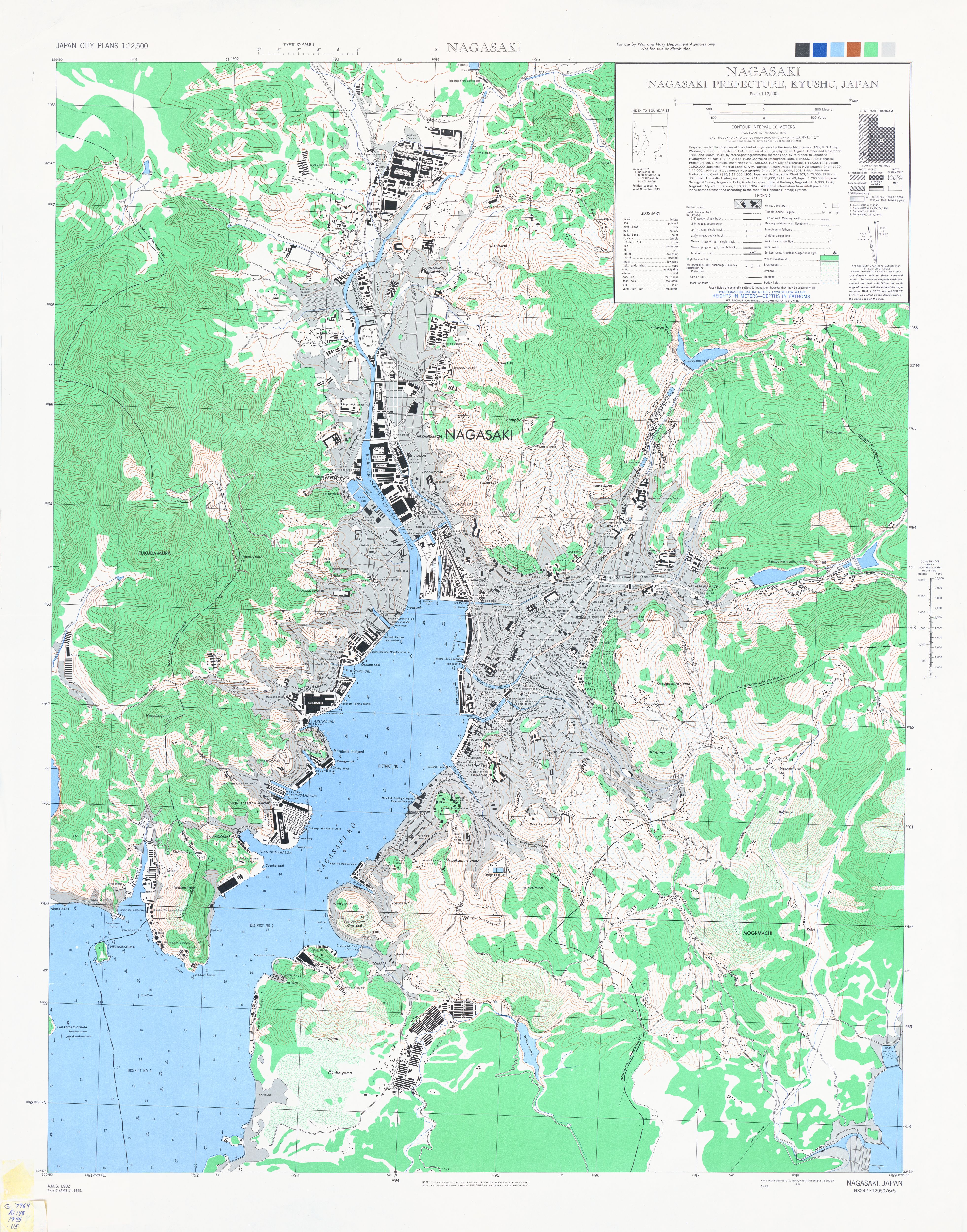
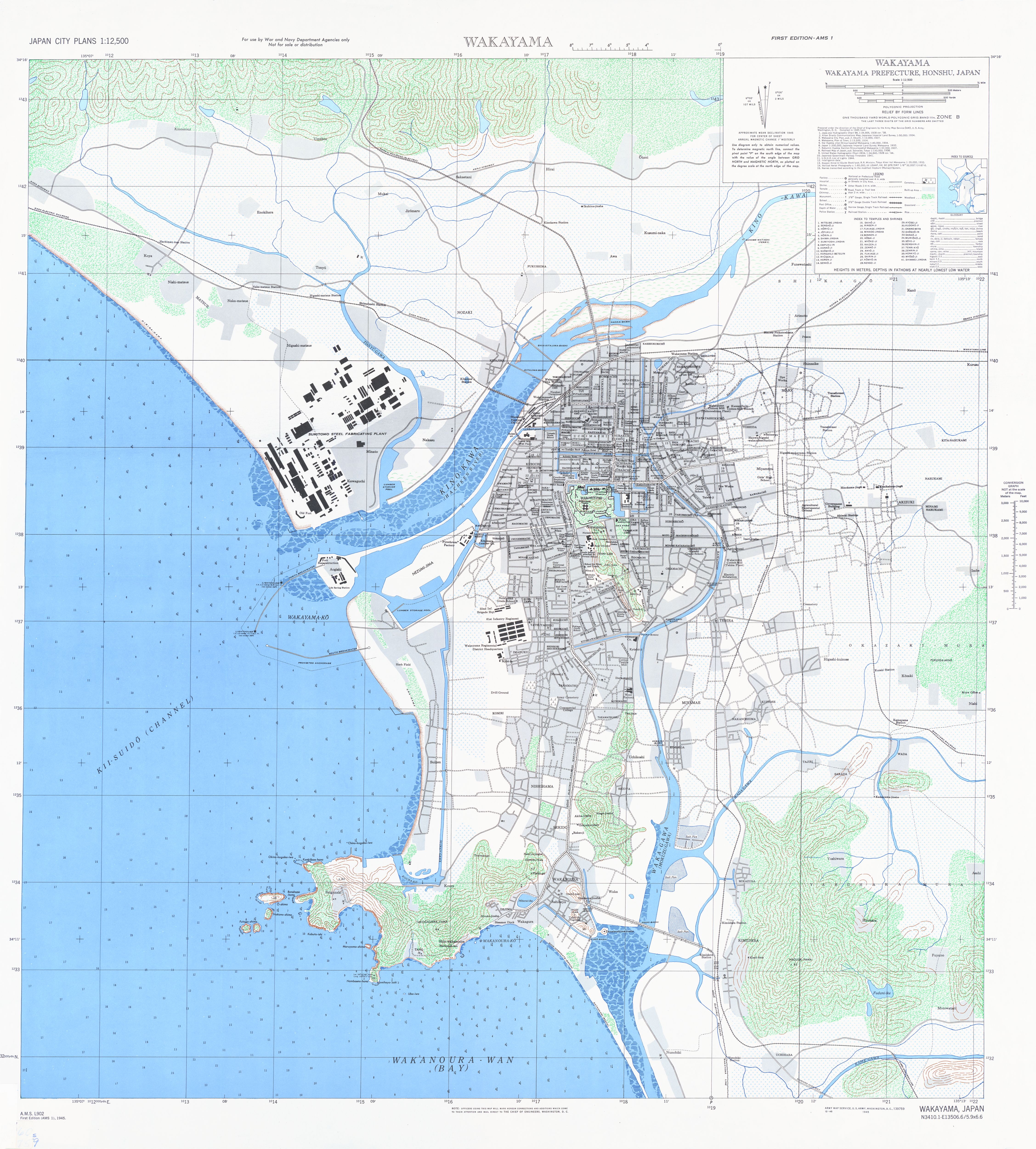
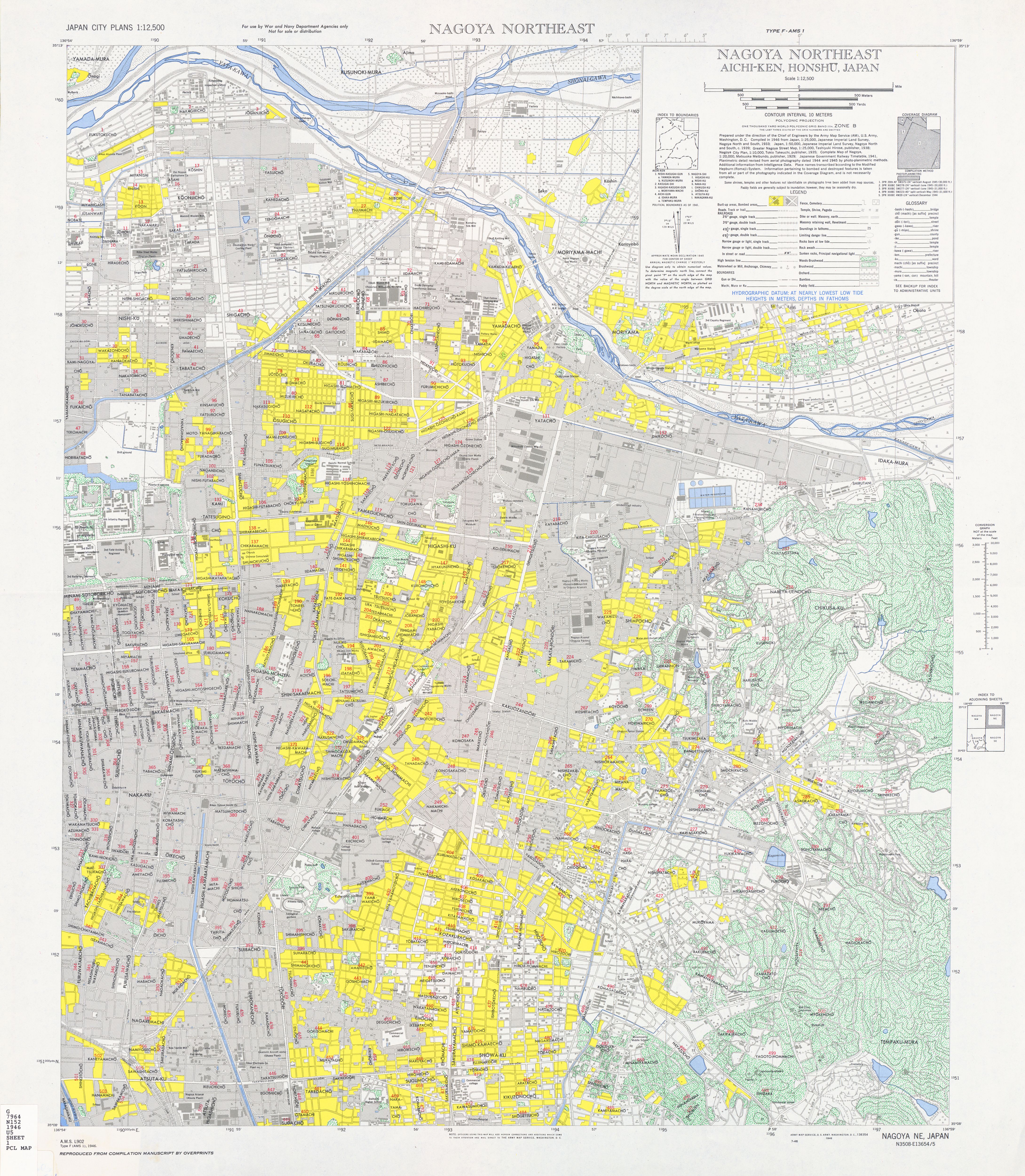
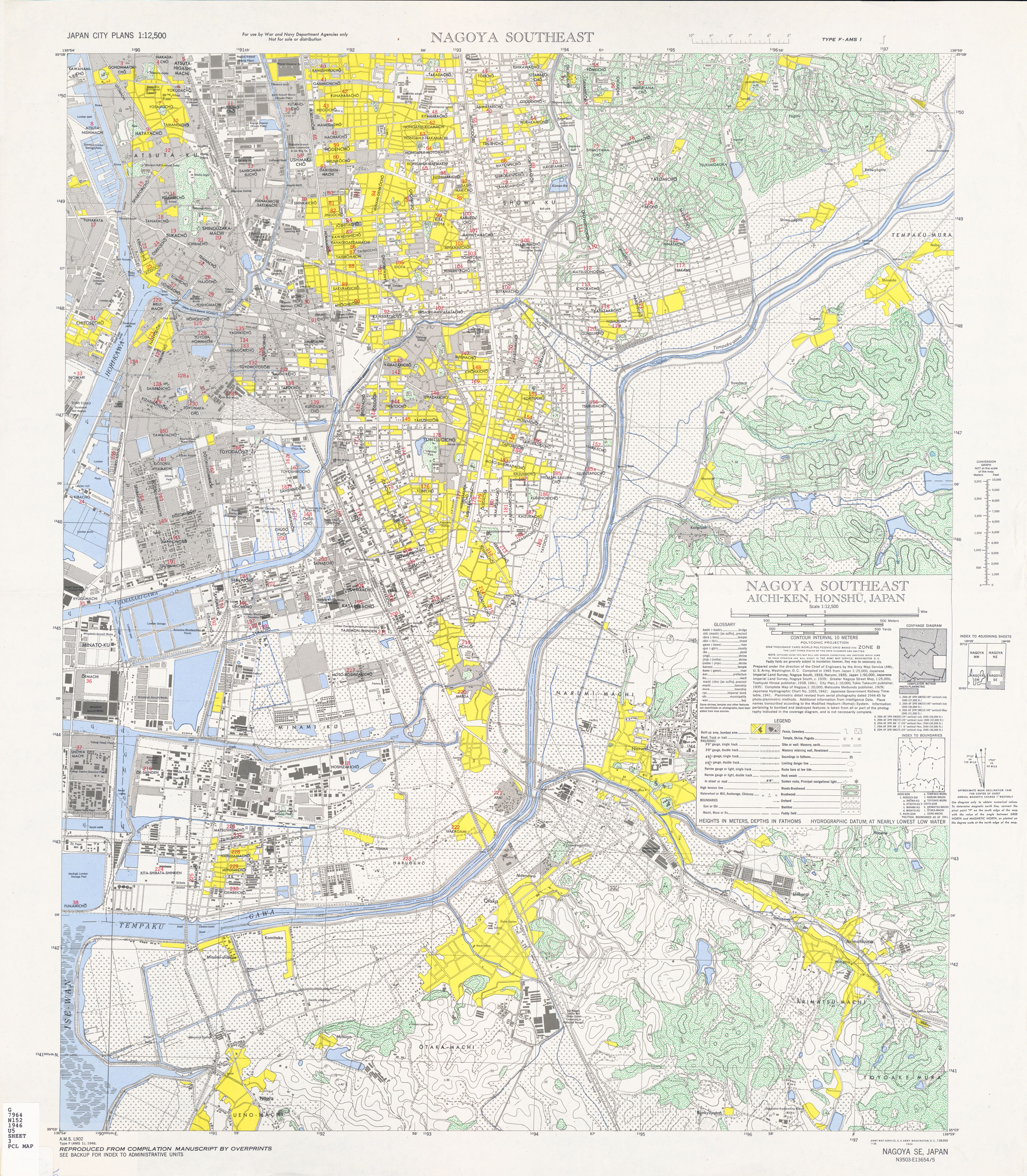
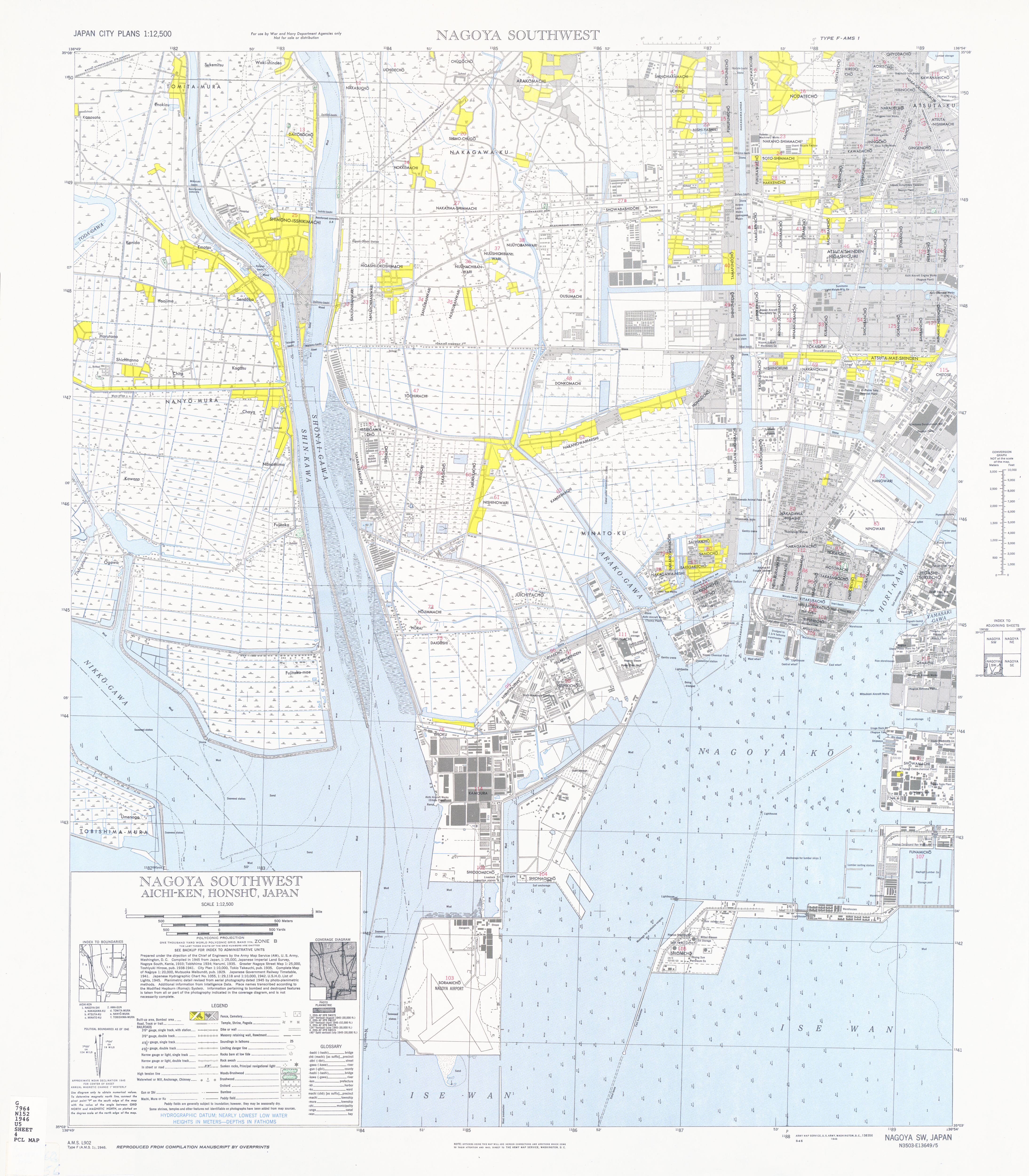
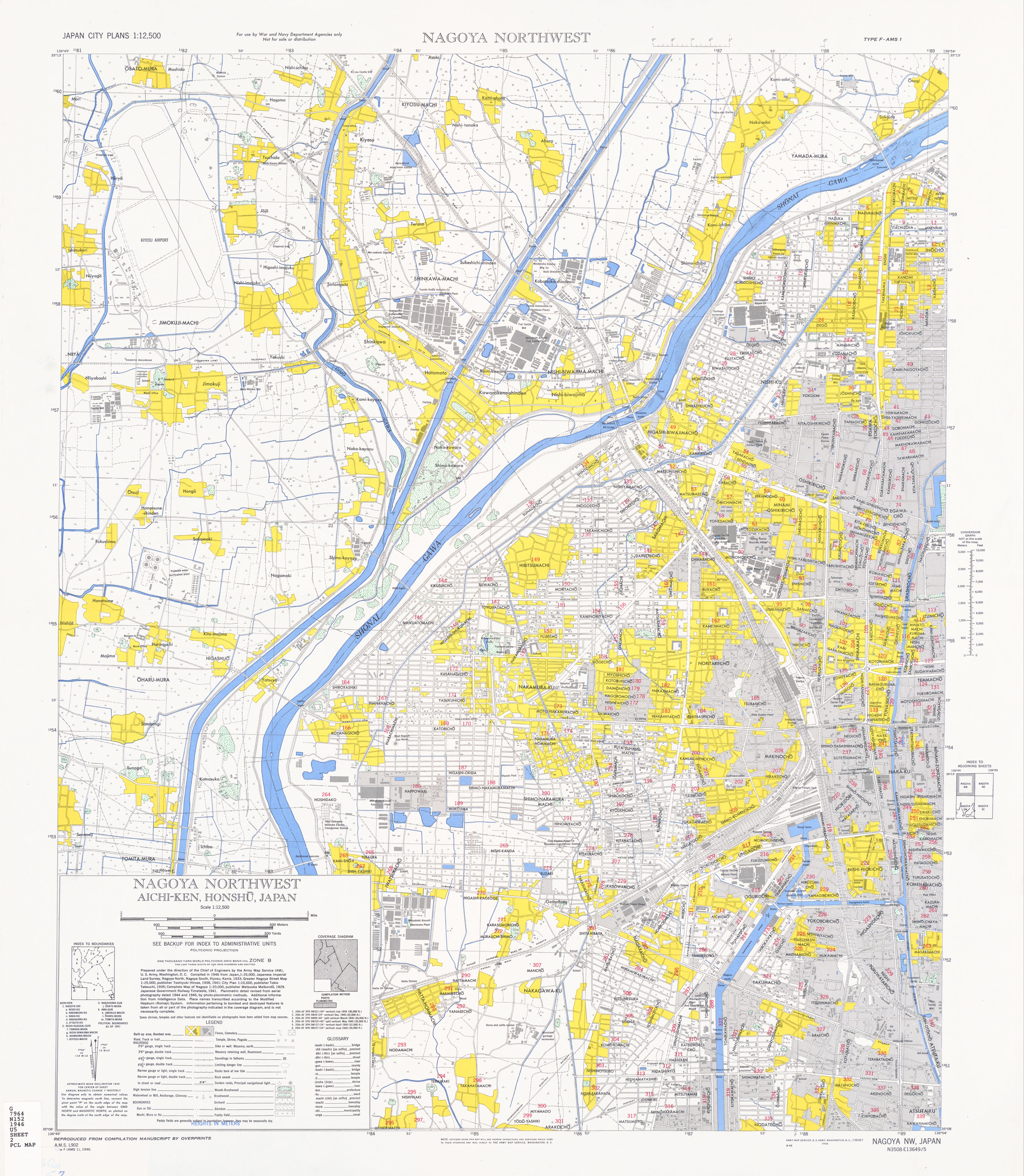
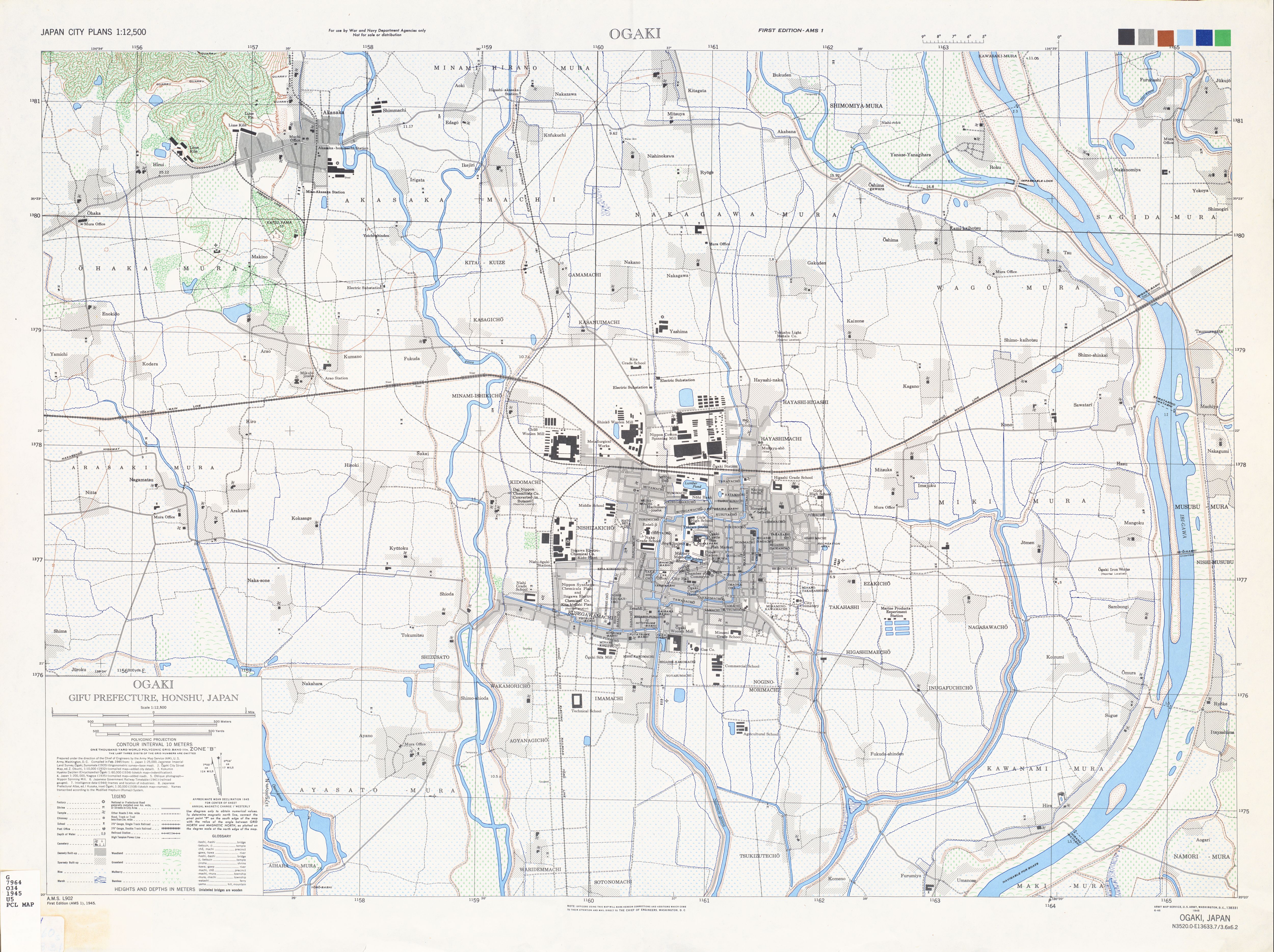
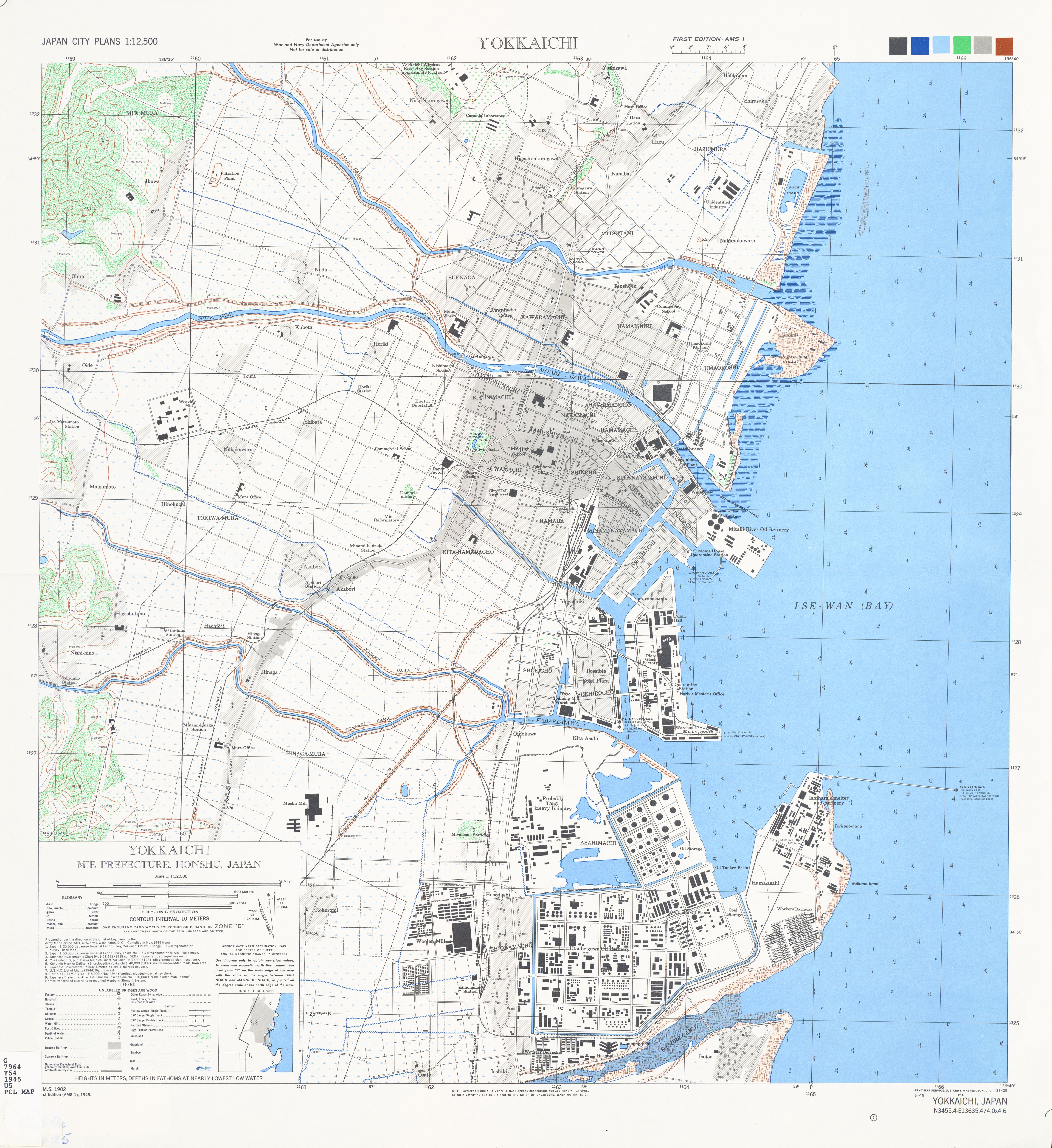
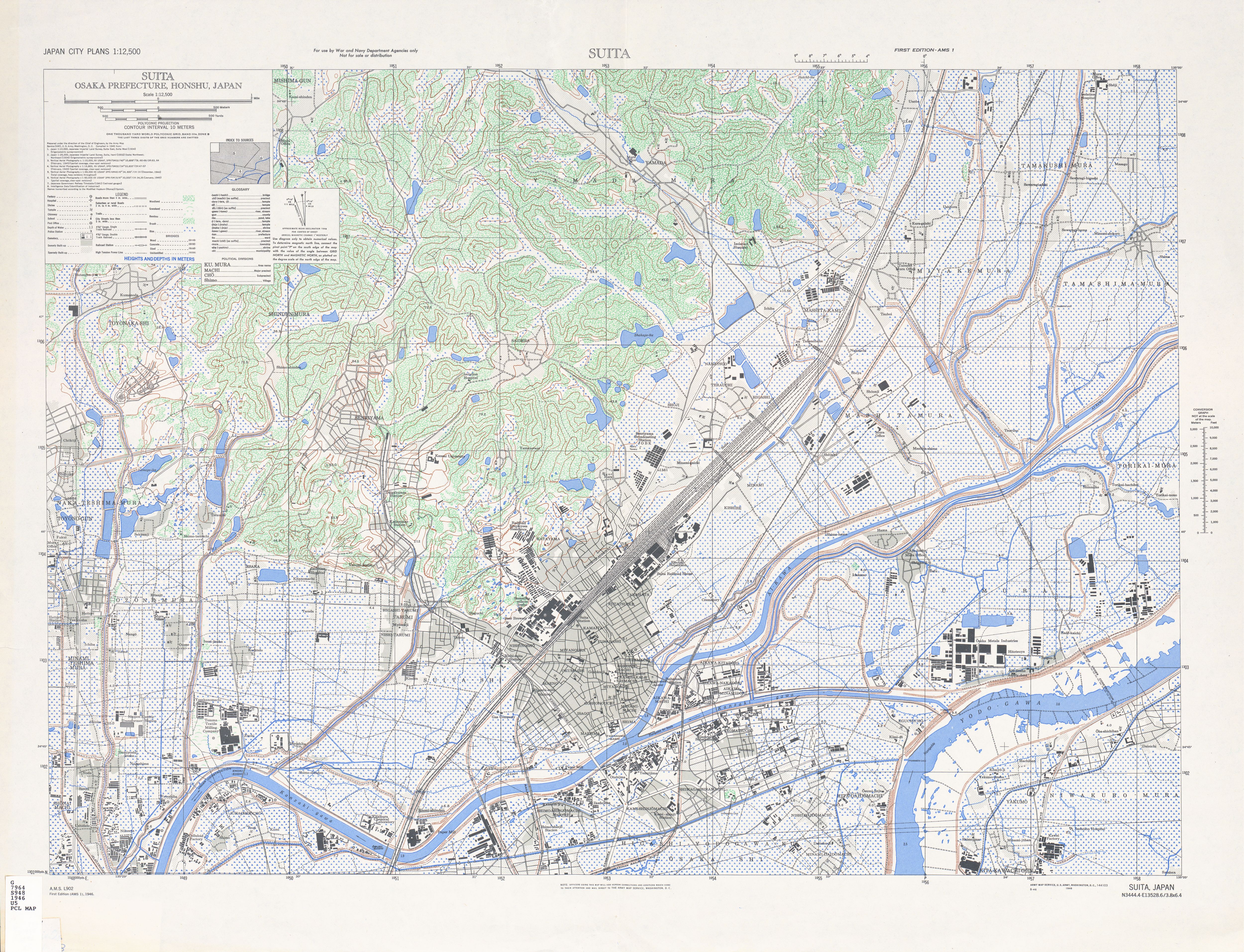
Japan City Plans 1:12,500 (U.S. Army Map Service, 1944)
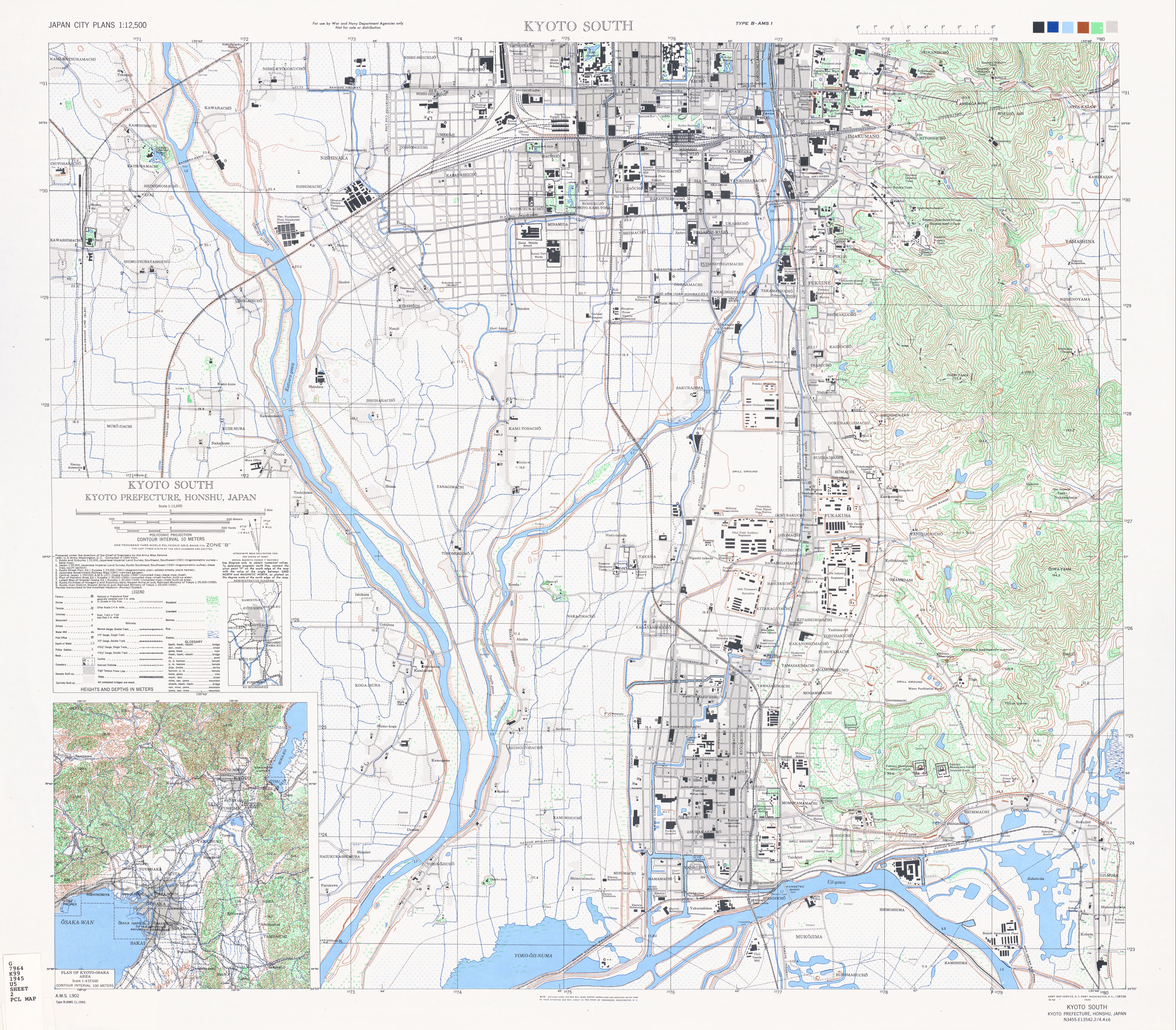
First and foremost, a VERY large thanks to the Library at the University of Texas at Austin. In the archives exists a set of maps of Japanese Cities that was used for military activities against Japan during WWII. These maps are of high quality and provide a snapshot of the layout of towns in Japan during 1945-46. Specifically of interest to me was the city map of Kyoto South.
I was busy inspecting the Umekoji roundhouse to the west of the main station when I saw (what looked like) a moat ... built of railway track. A square border exists on the map, and since Kyoto was the ex-capital, I initially thought it was a fortification. It then became apparent, after looking down the very west 'wall' that it was, indeed, a tram track. There was a specific gap that had the small note: "PROJECTED CAR LINE".
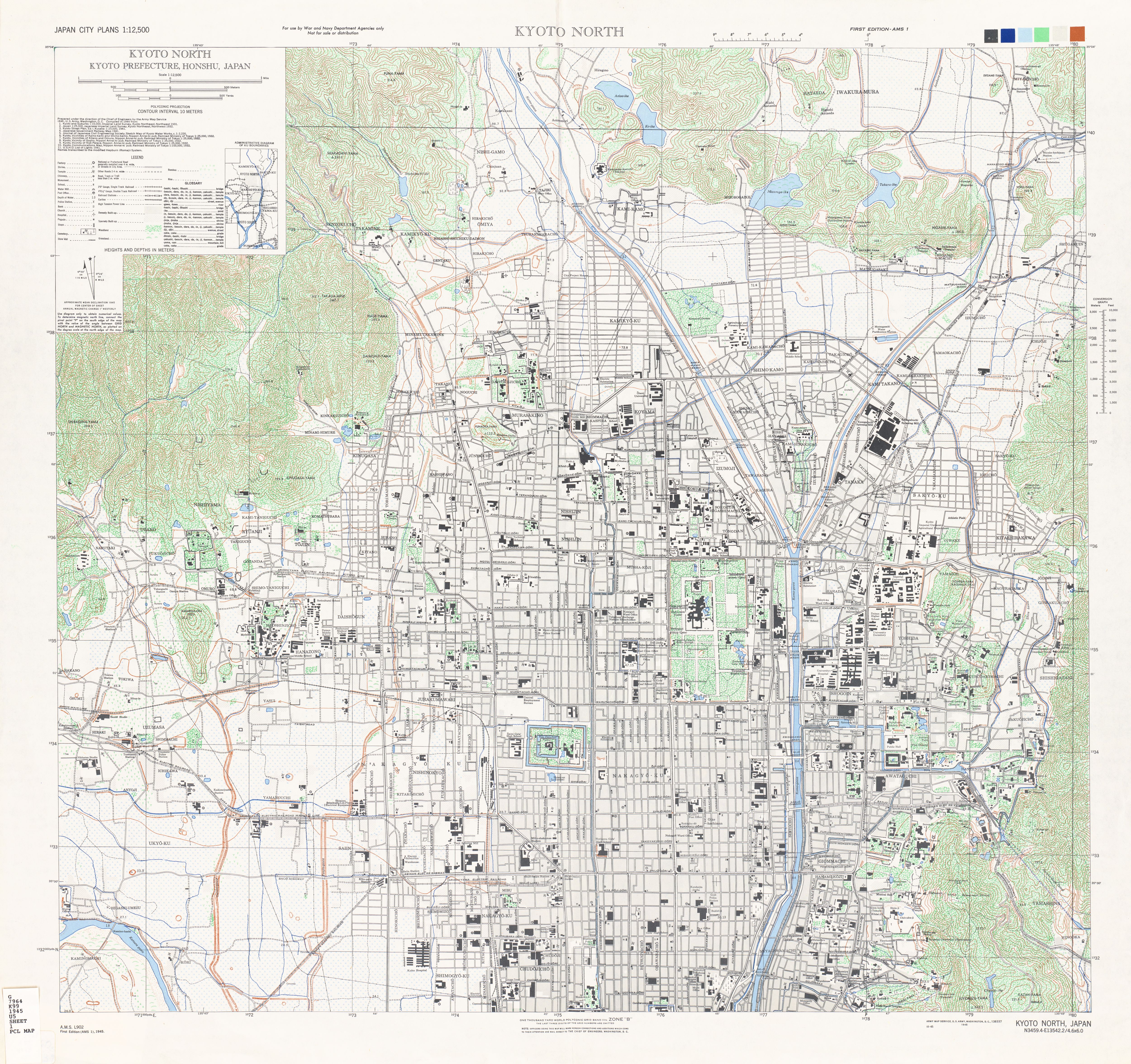
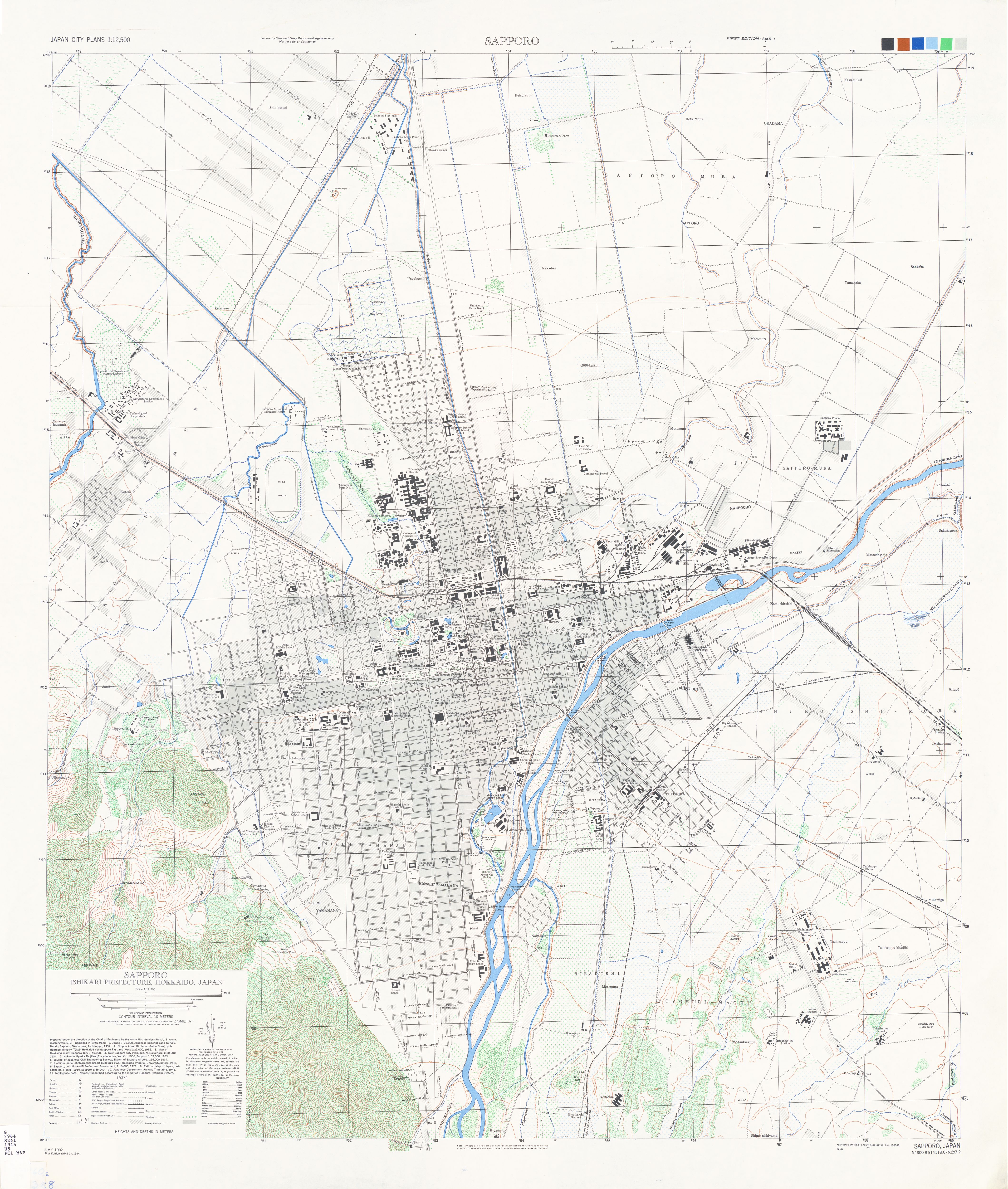
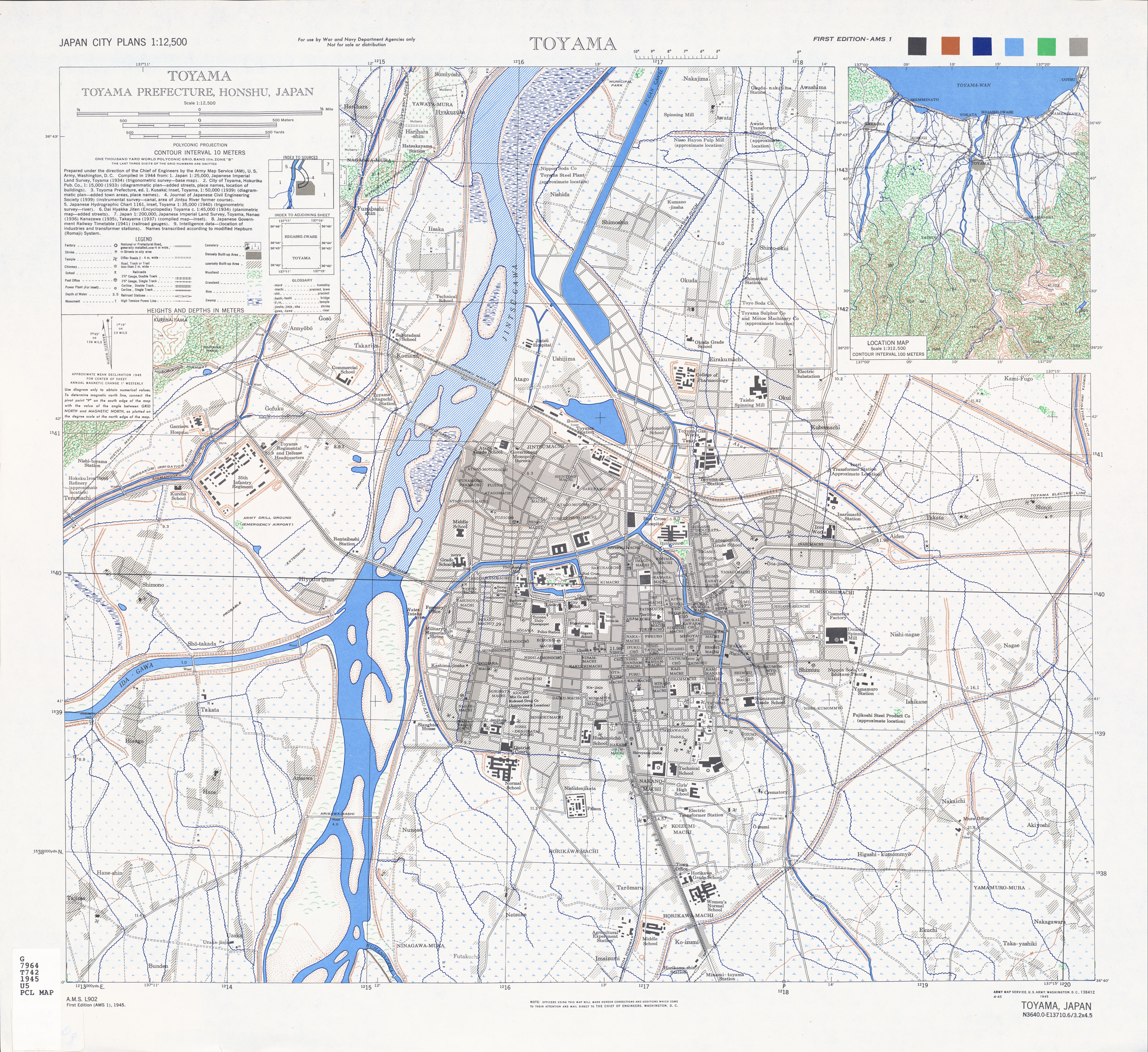
Note: There's maps of a lot of different cities in Japan. Check out the index here. Some notable maps: Kyoto North, Sapporo, Sasebo, Toyama, Nagasaki, Wakayama and Ichinomiya (with good overview of Nagoya). Nagoya actually gets a lot of maps: north-east, south-east, south-west and north-west. The mines in Ogaki get a map and so does Yokkaichi... these are the areas I've visited before around Minoakasaka and Tomida.
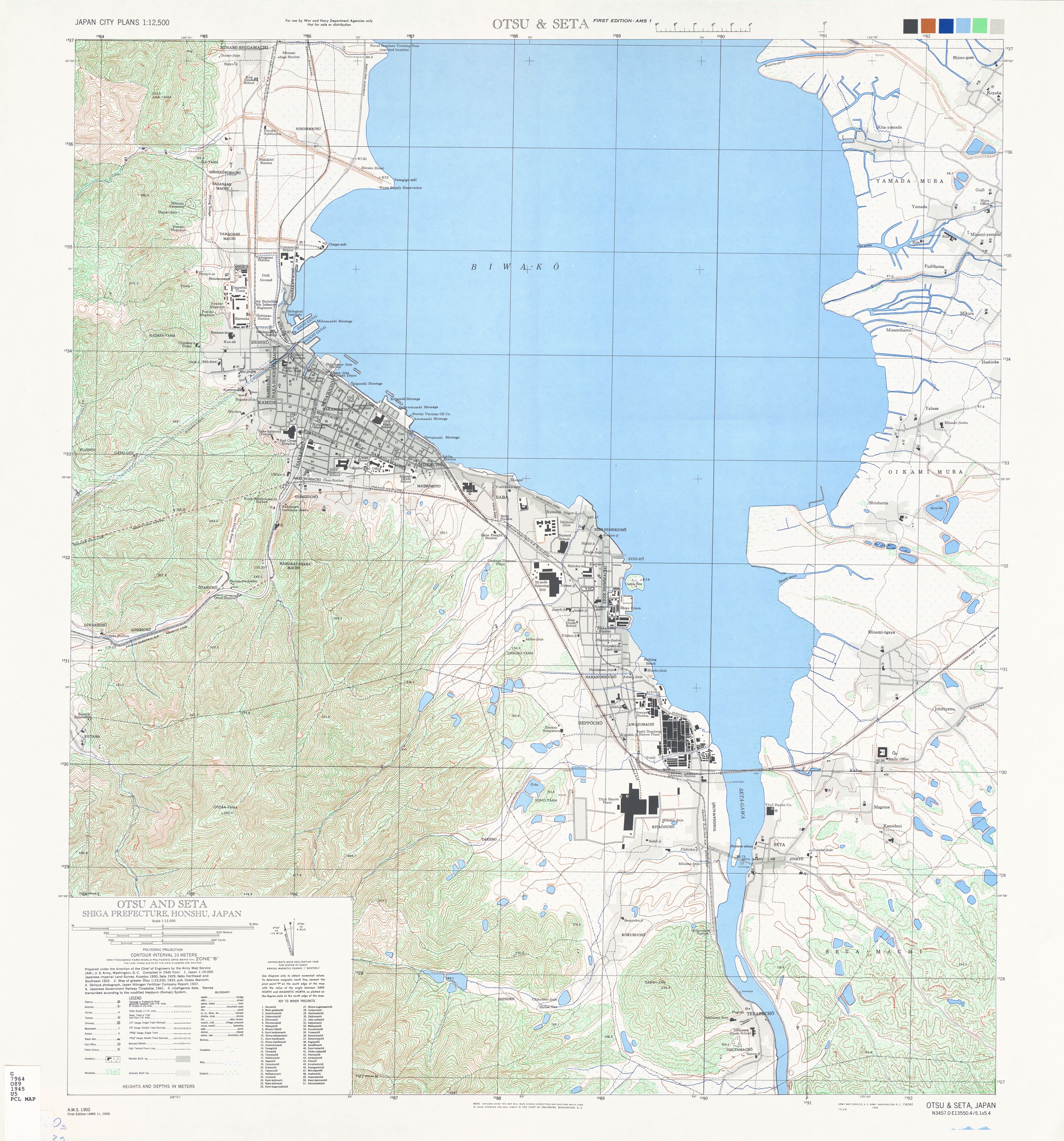
There's a lot of data in those maps. They mainly cover industrial/factory areas so that they could've done real damage to Japan's industry. Osaka doesn't seem to get a mention! The closest the maps get are Suita (OK, that's really close), Otsu and Seta, Yokkaichi and Wakayama.. but I'm repeating myself.
Kyoto City Tram (京都市電)
From the wikipedia article, the Kyoto Municipal Transportation Bureau ran the 京都市電 Kyōto Shiden Tram Network up until 1978. Ridership reached a peak in 1946, a second peak in 1955 and then progressively dropped towards 1978. The network was then closed in stages.
Studying the WW2 maps showed where the network was at the time. Intriguing, I had never known there was ever an 'outer loop' tram line of Kyoto. Tracing this around, I then found there were lines flowing south-east as well, down to the river adjunct with Inari Station and also south down to Station.
In the map below, you can see the alignment horizontal from the road that stops on the left. It seems there was also a bridge over the canal, but the maps I've seen show that the terminus was on the west bank (Just below the Neko Cafe TiME!!)
And down at Chūshojima, you can see where the trams veered east from their north-south direction into the station. The road indicates where the tram line was. The station building (where the blue station symbol is) was actually the tram terminus.
Umekoji still has a running example
At Umekoji roundhouse in Kyoto, it turns out there's still a functional example with it's own tram line. The museum is to be expanded in the near future, but I assume that the tram-line will survive.
From the shot below, you can see the line running from the south-west clockwise around to the north tip of the precinct.
There also seems to be a lot of preserved street cars around the museum. They're listed as "Umekoji Park", so I don't quite know if this is in the precinct or in the park to the east. I'll find out and update this when I visit the museum next. Read further down to see where the surviving rolling stock are located...
Did they ever finish that projected car line?
Check the map out here, you'll see that the US surveyors indicated that there was a strip of track that wasn't completed at the time. This map was created in 1944 from a miriad of sources. Check the bottom-right of the map to see who they used to create it.
The line is known as Nishiōjisen (にしおおじせん) 西大路線. There are two maps referenced on the main wiki page: the first one seems to indicate that this missing track is between 4th and 7th blocks (Nishiōji Shijo - Nishiōji Shichijo) and the second one doesn't show the outer loop at all!
The wiki page for the actual line indicates that trams were running from the June 3rd, 1935. The line was then extended further north with the connection from 7th to 9th blocks operating from December 12th 1938. If the maps were created in 1944, then their intelligence could have been quite wrong?
Other surviving rolling-stock
- Oomiya Kotsu Koen has No. 1 and 1860.
- Meiji Mura has No. 8
- I can't determine the location of No. 27. Who can translate this: "旧烏丸車庫で保存時代。復元・動態保存前、1982年6月1日撮影"
- Kyoto's Heian Shrine (平安神宮神苑) has かつての京都市電2両.
- Umejoki Park has 505, 703, 890, 935, 1605 and 2001.
- Ansho Elementary School has 726
- The Old Pueblo Trolley organisation in Tuscon, Arizona has 869 (Who would'da thought!)
- Kyoto Computer School has 1801 and 2603.
Further References
旅鉄おとーはん has a nice gallery here: 懐かしの京都市電ギャラリー. There is also a page with a map of the Kyoto Tram network!
むーさん has a great set of pages with random tram networks from Japan (it seems to be a quiz): 宮さんの全国路面電車アトランダム № 1. "No. 4" is a shot from Kyoto. Also here (No. 3) and then a whole page with shots of the network from 1961.
Conclusions
Declining ridership saw the end of this network... just another city to lose another form of transport. Sydney, Australia is a prime example of this! Will have to check out a few of the old alignments when I'm in Kyoto next.
Steamers in the UK (London 2014)
Have always loved the A4; specifically the Mallard: the fastest steam engine on record and simply put, a beautiful engine. I was over in the UK for NYE and was lucky enough to be there for The Bittern Farewell Tour to Lincoln from Kings Cross. Unfortunately, the tour was all sold out prior to me even knowing about it. In the end this didn't matter as I happily settled for a few line-side photos.
Prior research
The A4 would run on the East Coast Main Line for the start of its journey and I therefore had to find out a good position in correlation with the sun. Turns out there's a great website called SunCalc which allows you to set the date/time and then browse the map to see where the sun will be. I also found a blog post by Jake Miille which gave a little more information on how to use the site.
It seems that, for the most part of the southern end of the ECML, the line runs north-south. This really isn't advantageous as the sun wont be at a good angle. I browsed around the line and had settled on either somewhere near Welwyn or a little further north at Arlesey. The viaduct just south of Welwyn North would've been amazing, but getting there on foot would've been a challenge. Also there was a lot of potential shadow around the stations, so I therefore chose Arlesey.
As I was researching, I stumbled across Trainspots. This sight has an amazing amount of detailed information. You're able to research any location in the UK to determine what travels through, when and where the best photo spots are.
The train was to leave Kings Cross at 7:51am, so the plan was to catch it there and then take a local train to Arlesey, hopefully beating the steamer.
The timetable
7:47 AM	Old Street >> Subway Northern towards Edgware [4 min (2 stops)]
	 7:51 AM	King's Cross St. Pancras
==== VIEW STEAMER ON PLATFORM ====
8:22 AM	London King's Cross >> Great Northern towards Peterborough [35 min (4 stops)]
	 8:28 AM	Finsbury Park
	 8:47 AM	Stevenage
	 8:52 AM	Hitchin
	 8:57 AM	Arlesey
==== VIEW STEAMER PASS Arlesey Station ====
Seems there's also a site to tell you what's actually coming through a location!?
Kings Cross
Beautiful station. Had breakfast at the Savanna Cafe on the concourse as I'd gotten there too early. Tickets were purchased to Arlesey and then I entered the platforms... good to know that you can loiter without too much trouble. Great open space too... turns out there were already a lot of fans hogging the end of the closest platform.
So... I went to the next platform along. Turns out it's longer and provided a better side-on view!
And then they were off... I had thought the diesel that dragged them in would have been dead-attached, but it stayed behind at the end of the platform. Always good to see steam under its own power.
The race to Arlesey
The steamer left in a hurry... I was actually concerned it'd kick my ass and I'd not see it... turns out I was wrong. I caught the next north-bound semi-express and passed the steamer just north of London.
At Arlesey, a lot of others had the same idea. I must've looked like a regular, as quite a few people asked for information. They were all quite surprised to hear that I'd come on the commuter and beaten the train from Kings Cross.
A few high-speed expresses came through and then we all heard the unmistakable sound of a steam engine powering north.
The lighting was as expected... could've been better, but I was very happy to see my first ever A4... the fact that it was also pulling its own train made it even better.
Staircases
The tube was a pretty cool system. Very cramped rolling stock... felt like a rollercoaster between some stations... but nonetheless practical and efficient. I am used to escalators in Melbourne and therefore became fascinated with the staircases in most tube stations.
Back to Welwyn North
When travelling to and from Arlesey I'd seen this station out the window of the expresses. It seemed that, because of the tunnels and viaduct on either side, the line through this station is only double-track instead of the usual 2-up/2-down. This, of course, meant that all expresses (and there are a lot of them!) have to be timetabled in-between the stoppers. It also meant that the expresses would be full-tilt right on the platform. I was not disappointed...
Freight Trains?
I'd tried to determine the best locations to find freight trains around London by scouring flickr groups for pictures. One such group, Freight Trains in London, seemed to show quite a few pictures around the Stratford area. I tried to work out by the track layout where the trains would be, but I didn't do too well. An entire afternoon of hanging at stations around Stratford and to the east of the station resulted in zero sightings. As per usual, just as I was about to head back to the hotel a freighter came. I think it was at Canonbury, but I can't be sure anymore.
...I think I'll go back to London in summer next time...
A quick note on interfacing with JSON services via C#
I'm sure there are 100s of ways to manually create classes for JSON objects and then decipher them upon web-service response, but I've just stumbled across a fantastic site called 'json 2 csharp' that creates the classes for you. Just slap in your response (try to get a fully-fleshed out one with as fewer nulls as possible) and it'll generate the class structure.
You can then use the NewtonSoft JsonConvert deserialiser to populate it.
An example
Here's a link: jsontest 'date' example. It produces the following response:
{
   "time": "05:13:02 AM",
   "milliseconds_since_epoch": 1425532382121,
   "date": "03-05-2015"
}
From here, you just copy the entire response and paste it into the text field on the json2csharp site.
Hit 'Generate' and the site will spit out the following:
public class RootObject //rename this!
{
    public string time { get; set; }
    public long milliseconds_since_epoch { get; set; }
    public string date { get; set; }
}
Note that 'RootObject' is a little boring... rename it to 'DateResponse'
Add a helper library to your code to easily pull JSON responses (and POST):
public static class JSONUtilities
{
	public static string GetJSON(string url)
	{
		HttpWebRequest request = (HttpWebRequest)WebRequest.Create(url);
		try
		{
			WebResponse response = request.GetResponse();
			using (Stream responseStream = response.GetResponseStream())
			{
				StreamReader reader = new StreamReader(responseStream, Encoding.UTF8);
				return reader.ReadToEnd();
			}
		}
		catch (WebException ex)
		{
			WebResponse errorResponse = ex.Response;
			using (Stream responseStream = errorResponse.GetResponseStream())
			{
				StreamReader reader = new StreamReader(responseStream, Encoding.GetEncoding("utf-8"));
				Console.WriteLine(reader.ReadToEnd());
			}
			throw;
		}
	}

	public static Tuple<HttpStatusCode, String> PostJSON(string url, string jsonContent)
	{
		HttpWebRequest request = (HttpWebRequest)WebRequest.Create(url);
		request.Method = "POST";

		System.Text.UTF8Encoding encoding = new System.Text.UTF8Encoding();
		Byte[] byteArray = encoding.GetBytes(jsonContent);

		request.ContentLength = byteArray.Length;
		request.ContentType = @"application/json";

		using (Stream dataStream = request.GetRequestStream())
		{
			dataStream.Write(byteArray, 0, byteArray.Length);
		}
		long length = 0;
		try
		{
			using (HttpWebResponse response = (HttpWebResponse)request.GetResponse())
			{
				length = response.ContentLength;
				using (var reader = new System.IO.StreamReader(response.GetResponseStream(), encoding))
				{
					return new Tuple<HttpStatusCode, string>(response.StatusCode, reader.ReadToEnd());
				}
			}
		}
		catch (WebException ex)
		{
			// Log exception and throw as for GET example above
			Console.WriteLine("ERROR: " + ex.Message);
			throw ex;
		}
	}
}
And now you can bring it all together:
private bool Get()
{
    var result = JSONUtilities.GetJSON("http://date.jsontest.com/");
    var dateResponse = JsonConvert.DeserializeObject<DateResponse>(result);
    Console.WriteLine("Got Response: " + dateResponse.date + " [" + dateResponse.time + "]");
}
Too easy!
JR West Thunderbird
I just happened across an eBay auction for a "Thunderbird" 7-Car consist in JNR red/beige livery which very much looked like a JR West Raichō or Kitakinki. After digging a little deeper, it turns out that the seller actually directly translated the Kanji of 雷鳥 to "Thunder bird". This, whilst literally correct, is a mistranslation of the train name which is, of course, the Raichō.
Little did I know that the JR West Thunderbird actually steals its name from the Raichō, which means "thunder bird" in Japanese. The bird is actually the Rock Ptarmigan, a native to the Tate[yama] Mountain Range of the Toyama region (which is where the train[s] travel to.)
Interesting to know that JR West first called the Express the 'Raichō', then released a 'Super Raichō' and then created a new service to the same area with the same name, but this time in english: the 'Thunderbird'.
Going through my galleries, turns out I have more shots of the Thunderbird than I care to remember!
The Thunderbird just happens to be one of my favourite EMUs. It's colour-scheme is a little dated, but the design and practicality (opening end-vestibules) is awesome. Not surprisingly, it also reminds me of the Dutch NS Koploper.
Model Railway Shops in Osaka
To make the guesswork easier, here's a list of terms that should help you on your never-ending-search-to-find-model-trains. To translate things, use Google Translate. To convert from Romaji, Hiragana, Katakana or Kanji use J-Talk's Kanji Converter
| English | Romaji | Hiragana | Kanji |
|---|---|---|---|
| Train | resshya | れっしゃ | 列車 |
| Electric Train | denshya | でんしゃ | 電車 |
| Steam Train | kishya | きしゃ | 汽車 |
| Diesel Train | kidoushya | きどうしゃ | 気動車 |
| Model | mokei | もけい | 模型 |
| Model Train | mokei resshya | もけい れっしゃ | 模型列車 |
| Railway Model | tetsudou mokei | てつどう もけい | 鉄道模型 |
| Gauge | geeji | ゲージ | -- |
| Shop | shoppu/mise | ショップ/みせ | 店 |
| ?-Shop | ?-ya | や | ?-屋 |
Den Den Town, Osaka
One of the most well-known Osaka hobby shops. A place you simply must visit. Has everything.
(Note that their Tsurumi shop is closed!)
Super Kids Land (スーパーキッズランド本店)
A large toy department store with a floor dedicated to model railways. A good selection of HO-scale too!
A cute little shop with a good selection of consists. Also a good bargain-bin for second-hand items. Note that they will be graded from A-D where D is quite broken!
Volks Osaka Showroom(ボークス 大阪ショールーム)
Another toy department store; you'll find the trains on level 6.
Shinsekai
Rail Workshop Higeshin (レール工房ひげしん)
A small store on the north-west corner of Shinsekai. I walked in and couldn't communicate, but there's glass cabinets of nice stock, both N and HO. The owner is usually there building models as well. Seems to have a 'club' atmosphere with regulars often hanging around to chat to the owner.
Note that Shinsekai is a relic of Osaka, planned/built as the 'suburb of the future' back from 1903.
Address: 大阪市浪速区恵美須東1-22-1
Uehommachi (East Osaka)
There's a good story behind this shop. I visited it in 2010 with a friend from university; her uncle actually works there. Back then the shop was south-east of Kintetsu Osakauehonmachi Station and it was a confusing walk from the station to get to it. The shop was small, full of glass cabinets and cutting boards. It had a great selection of N-scale and HO, specialising in paper kits. I remember that there were a lot of full N-scale sets, some 'custom made' and painted to prototypical awesomeness. I bought a DE10 and a set of passenger cars, beautifully detailed.
The shop has now moved here and, although I haven't been back since it moved, it seems to be a bigger and better presence with full layouts for demonstrations. It also seems a lot easier to get to!
Umeda
Haven't been to this one, but can only imagine it's just like its brother in Den Den Town.
Another department store... trains are on B2. I always end up going here since it's so close to Osaka Station and I can send my friends to other levels if they don't want to check out trains.
This shop actually seems to be pronounced ma-ha mokei; but for some reason they've translated that to 'mach'.
Minamikata
Someone go and check this place out!
Awaza
Review to come....
Hanakawa (North-East)
Haven't been to this one, but can only imagine it's just like its brothers.
Toyonaka (North)
Review to come....
Takastuki
Recycle Shop (Ryouhin Kaikan) (HobbyDo!) ![]()
I accidently stumbled across this shop. I'd bought a bike for my 4-week stay in Shinosaka and had been riding east towards Kyoto. The Tokaido main line and Shinkansen are both out that way and can be seen up quite close. Anyway, this shop is walking distance from JR Takatsuki Station, but closer to Hankyu Takatsuki-shi Station. Head due-east from either and then north-east along 国道171号線 (Japan National Route 171).
The shop has a great selection of new and second hand goods. I especially loved rummaging through the box of B-Train Shorty odds-and-ends. It seems that they had many split up boxes of B-Trains and each component is individually priced. Just remember, when you get to the counter things always add up!
Matsubara
Mokei-ya (Model Shop) (もけいや松原) ![]()
From the website, this place seems to have a lot of stock. Has anyone been!?
Kobe
(This used to be in Amagasaki, but that closed)
庫県神戸市東灘区青木1-2-34 サンシャインワーフ神戸1F
Haven't been to this one, but can only imagine it's just like its brothers in Den Den Town and Umeda.
2 Chome Sannomiyacho, Chuo Ward, Kobe, Hyogo Prefecture, Japan.
EMU Staging Yards, NE Takatsuki
These photos were taken back in January 2008. I'd hired a bicycle and had been dawdling along the Tokaido Main Line from Shin-osaka through to Takatsuki. I'd made it all the way to the staging yards just north-east of Takatsuki (Google Maps seems to indicate the area is known as 'Amanishinocho') before turning around to return to Osaka.
I stopped and took these shots from the pedestrian crossing visible in the map above. I can't quite believe that it isn't an overpass. I don't know if this crossing still exists today.
Towards Kyoto...
And towards Osaka...
My Favourite Shinkansen: 300 Series
This photo was taken with a second-hand (and then damaged by me) Fujitsu Finepix back in 2006. It was my first meeting with the 300 Series and it was love at first sight.
I can't believe they've already chopped this model up.
Regional Rail Link
The Regional Rail Link is the Victorian governments answer to traffic congestion between Footscray and Werribee. The goal is to build a new line to Geelong via the north of the area and bypass it entirely. Of course, this will just move the regional trains, the sparks will still service the bypassed area.
On the capture below, you'll see a V/Locity testing the tracks at full speed. This happened this morning. It's interesting to see that there are data points missing around Deer Park.
The same consist then returned via the loop. A fellow fan mentions that this was to keep the drivers memories of the route fresh and to keep the rust off the rails.
The entire section is expected to be in operation in April this year.
Random Photos
Search
Tags
Links - Click for details
- Abandoned Rails (Japan)
- AIRLINE (Shinkansen Photography)
- Akihabara Station
- annexpressのブログ
- Australian Model Railway Magazine
- DCC普及協会ホームページ (Japanese DCC)
- Dead Section (Japanese Track Diagrams)
- Delicious Things (Japanese N Scale DCC)
- Densha Wotorou
- Digital Direct for Windows (DCC Server)
- Don's Dream World – AMAZING N Scale Japanese Layout
- Hatena::Diary
- Japanese N-Scale Modeling Forum
- JR Chiisai
- Kaz-T's blog レインボーライン (Rainbow Line)
- LED Resitance Calculator
- Masioka
- Poppondetta Blog
- RailFan Magazine, Japan
- Railmind
- Railway Travelers' Room
- Serenity Valley
- Shashinka Ichiban
- Shuzuku
- Sumida Crossing
- The next station is…
- Tomix N Gauge Track and Japanese N Gauge Trains
- TT Forums (Transport Tycoon Deluxe)
- 名鉄尾西線の貨物列車 (Nagoya: Meitetsu Freight)
- 日本型Nゲージ DCC改造例のご紹介 (Okiraku DCC)
- 泰 茅 轍 道 (Taichi Railway)
- 箱庭登山鉄道製作記 (Hakone-Tozan Layout Blog)
Archive
- July 2026
- May 2026
- April 2026
- March 2026
- February 2026
- January 2026
- November 2025
- October 2025
- September 2025
- August 2025
- July 2025
- June 2025
- February 2025
- January 2025
- November 2024
- September 2024
- August 2024
- July 2024
- June 2024
- May 2024
- April 2024
- March 2024
- February 2024
- December 2023
- October 2023
- September 2023
- August 2023
- July 2023
- June 2023
- May 2023
- April 2023
- March 2023
- December 2022
- November 2022
- October 2022
- April 2022
- March 2022
- February 2022
- January 2022
- December 2021
- November 2021
- September 2021
- August 2021
- July 2021
- May 2021
- March 2021
- February 2021
- January 2021
- October 2020
- September 2020
- August 2020
- July 2020
- June 2020
- May 2020
- April 2020
- March 2020
- January 2020
- December 2019
- November 2019
- October 2019
- September 2019
- August 2019
- July 2019
- June 2019
- April 2019
- March 2019
- February 2019
- January 2019
- December 2018
- November 2018
- October 2018
- September 2018
- August 2018
- July 2018
- June 2018
- May 2018
- April 2018
- March 2018
- January 2018
- December 2017
- November 2017
- October 2017
- September 2017
- August 2017
- July 2017
- June 2017
- May 2017
- March 2017
- February 2017
- January 2017
- December 2016
- November 2016
- October 2016
- September 2016
- August 2016
- July 2016
- June 2016
- May 2016
- February 2016
- November 2015
- October 2015
- September 2015
- August 2015
- July 2015
- June 2015
- May 2015
- April 2015
- March 2015
- February 2015
- January 2015
- December 2014
- November 2014
- August 2014
- July 2014
- May 2014
- April 2014
- March 2014
- December 2013
- November 2013
- October 2013
- June 2013
- August 2012
- April 2012
- March 2012
- February 2012
- November 2011
- October 2011
- September 2011
- July 2011
- June 2011
- May 2011
- April 2011
- March 2011
- February 2011
- January 2011
- December 2010
- November 2010
- October 2010
- September 2010
- August 2010
- June 2010
- May 2010
- April 2010
- March 2010
- February 2010
- January 2010
- December 2009
- November 2009
- October 2009
- August 2009
- January 2009
- December 2008
- November 2008
- October 2008
- September 2008
- July 2008