


 Melbourne BG SCS Train Timetable


Dual Technologies SKD-4000
This beauty had been doing laps on eBay for a while. I had tried to low-ball it early on, only to receive a swift declination. A week or two later, I offered a little more and it was accepted! The seller took no time to send it to me, perfectly packed. It was listed as untested and with a cracked front-right case. Indeed it was, with one of the plastic clips actually hanging out the front of the opposing top-half, looking slightly like a buck-tooth.
After a little googlin', I came across a site talking about a slightly different version to this laptop. Turns out Dual Group were a Taiwanese manufacturer and built laptops that were then re-branded and on-sold. They therefore didn't really have their own site with any relevant info on this laptop. If anyone manages to find any information on this laptop, then please get in touch in the comments section! I therefore kept inspecting the unit, disassembling what I could prior to needing a screwdriver.
This unit didn't have a power supply, but thankfully the link above provided a pinout for the power supply their SKD-4000 needed. Under this unit, it stated it needed DC 20v @ 1.0A, so I tinned up a set of power wires and dialed in the voltage.
Jamming the wires in the power socket, after continuity-testing for GND, I flicked the power switch... lo'an'behold: the full orchestra of a vintage HDD and a POST beep!
The joy was very short-lived though... the BIOS quickly reported a low battery and incorrect date/time. Hardly surprising! I went into the BIOS anyway and did a HDD auto-detect.
116mb, nice! I saved the config and rebooted, but nothing seemed to have stuck. Seems I'll need to replace the battery to get further. Before that though, does VGA out work?
Nice! Ok, back to the CMOS battery. The link above provided a tear-down guide to help me, but in the end I didn't really need it as this laptop was surprising easy to open and work with! Even the CPU had a flap for easy access? It also has DIP switches for setting the CPU and they seem to configure the CPU pins directly? I'll try and decode them shortly.
The CMOS battery is a piece of work. It's hard-soldered in and it happens to be a rechargeable coin-cell. These are pretty rare nowadays... and... stupid me... I just tried to solder in a coin-cell holder and use a CR2032. DO NOT TRY AND USE NON-RECHARGEABLE BATTERIES IN-PLACE OF RECHARGEABLE BATTERIES!
Turning the unit on saw the coin-cell heat up rapidly, but fortunately I had my finger on the power switch, ready to prevent any spontaneous combustion. I then tried a 3.7v cell I had lying around, but the laptop started reporting 10 error beeps indicating that no battery was available at all. I really do hope I haven't trashed the charging circuit. At this point, I ordered an exact replacement Panasonic VL2330 battery and then looked for other things to fix up.
Power Plug
Whilst waiting for a battery to arrive, I realised I should solidify the power supply. Seems this type of plug is called a SnapNLock 4-Pin Mini DIN and I was pleased to see it available at Jaycar. I purchased a few (luckily) and attempted to wire one up. Soldering it was easy enough, but assembling it was next-level.
I mean, just look at the datasheet (which, actually, wasn't even east to find!), and you'll see what I mean... 8 components to jam together in a not-so-obvious order. I trashed the first plug and sorta-but-not-really succeeded with the second plug... it was good enough to test with.
Dip-Switch Dissection...
There are two blocks of four switches and, with no documentation, I set about trying to determine what these might control. Looking at the set closest to the CPU first, one can find the traces run off CPU pins.
Thanks to the glory of the internet, one can find pin maps and descriptions of pins readily available. The latter doesn't go into much detail, so actual CPU datasheets can also come in handy. After a little digging, it seems this block of switches controls maths error handling and interrupt line access to the CPU. I might just leave them as-is.
| Dip-switch Name | Solderable-jumper name | Connected CPU Pin | Pin Function | |
|---|---|---|---|---|
| JP1-1 | JP44 | B15 | NMI - Non-Maskable Interrupt | |
| JP1-2 | JP41 | Can't tell... but seems to toggle the signal from JP1-1 through to JP3. | ||
| JP1-3 | JP42 | A15 | IGNNE# - Ignore numeric error | |
| JP1-4 | JP43 | C14 | FERR# - Floating Point Error |
The second block's traces disappear into the board's layers and are impossible to trace and understand.
The BIOS
Just for fun, I popped out the PLCC32 and read it in my Willem Programmer.
You can download the BIN file here.
Back to that Battery
A proper Panasonic VL2330 arrived and I soldered it in place. Applying power heard the same beeping. Ok, let's follow the traces to the left and see what's going on... two diodes, both seem to conduct power... then the voltage goes into pin 20 of that IC... with no marking? Why no marking?
Under the right light, it turned out to be an Epson RTC-6593 Real-time Clock. It even has integrated battery-backed RAM! Of course, this unit stores my BIOS settings. Why has the label disappeared? It's COOKED! It tried to burn me when I touched it. We can only assume it's due to my testing of other batteries... if only I'd bought the correct replacement at the start.
Replacing the RTC
So, I'm game to try this... what I'm not game for is fake chips! Searching for this IC has only come up with seemingly-dodgy sellers on Alibaba and eBay. I've just thrown in a few orders and we'll see what comes back. In the meantime I've removed the existing IC and cleaned up the area. Interesting to note that the silk-screen shows the IC should be an RTC-6583, whereas a 6593 was installed. The datasheet seems to indicate that 659x has "Extended Alarms" whereas 658x doesn't.
During removal of the chip, I just happened to remove a pad... I blame the fact that the IC was actually glued down to the board! I couldn't work out why the IC wouldn't move, regardless of the pressure I applied. Furtunately, it was a quick fix with winding wire and it's ready to solder up.
I'll post a Part II once the ICs have arrived.
The Royal Express Visits Hokkaido (Again)
It's been a while, and there's a lot to post, but for now I'm catching up on trains. Actually, this isn't catching up at all... this train is touring Hokkaido as we speak. The Royal Express is a ridiculously beautiful electric set train that runs (usually) from Yokohama to Izu-Shimoda on the Izu Peninsula, but, due to Tokyu Corporation being perfectly adventurous, is running on non-electrified lines in Hokkaido!
It's an ELECTRIC TRAIN! You say? There's very few overhead wires in Hokkaido, you exclaim!? You'd be correct! To run this tour, they have employed two freshly-painted DE15 locomotives and a mail-car-come-generator-car painted in white, to (literally) tow the electric train through the beautiful pastures of Hokkaido.
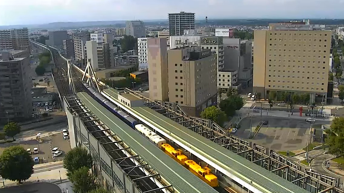
Thanks to the current world order: we can't travel from Australia to Japan, but thankfully we can watch! Japan has a fantastic acclimation to rail-side webcams and a hotel in Obihiro has actually mounted one on their building with a perfect view of the station. The same team have also provided views of the airport and a famous bridge. Note that these links change all the time, so please just browse to their channel to find what they're offering!
Anyway, where was I? Oh yeah.. the tour train has actually already operated this route twice this season. Thanks to lockdown, I haven't been in any correct frame to be alert to its movements. Or maybe I was just working? The train passes the Obihiro Station webcam just after 4pm Australian Eastern Time and, well, it's knock-off for anyone starting on-or-prior to 8am.
Fortunately, I set my alarm today and caught it!
So yeah, double-DE15 + white power van + Royal Express EMU. Who would've ever thought to tow an EMU on 'genny'-power with two very light-weight diesels!? It's actually amazing on a many levels: reliability, engine-weight, loading-gauge... the list goes on.
Anyway, for those playing at home, Obihiro Station is a major freight-accepting town (the yard is further to the left/west of the camera), but has single-lines on either side. This means that, if you see a train, regardless as to whether it's meant to actually stop at Obihiro, it'll at least pause on the camera as there's line-working preventing it from proceeding. There are freight, Limited Express Tokachis (to the west) and Limited Express Oozoras (both directions) on the line at all times and there's always another service to wait for.
So yeah, it waited... and the westbound Oozora from Kushiro arrived.
Not long after, The Royal Express departed for Ikeda and the Oozora went onwards to Sapporo. From here it'll do a full loop, turning north at Kushiro (I want to do that next!) to Kitami and then back through Asahikawa. When this current world situation is over, I'll be doing the same!
Update: 04/09/2021
The Express De Royale has left on another lap, in delicious sunshine:
Enjoy patrons, enjoy.
DCC via an Arduino!
And now, back to the topic that started this entire blog: DCC! Back then, I was creating breadboard circuits to get a PC to talk DCC, and although it worked, it has now been made much easier thanks to the Arduino platform. All you need is a motor shield and an Arduino Mega! It seems that DCC on the Arduino started as a project named DCC++. Sometime around 2016, the 'great rewrite' occurred and DCC++EX was born. What follows is what's required to get this up and running in no time!
First off, you need a supported Arduino with a matching motor interface. My expectation is to use my PC to control the DCC trains, so I wont need any extra throttle hardware. For any electronics projects, make sure you have a solid power supply. Especially with DCC, which requires intricate signals running over the model railway rails, you should follow the power supply guidelines here, preventing any further issues.
To make life easy, I purchased a legit Arduino Motor Shield from Core Electronics and attempted to plug it into my Arduino Mega 1280... used in most of the Arduino posts on this blog.
Turns out, my Mega is so old that the pins don't even line up! Seems that the pin layout changed at some point in the last 11 years.
Luckily I had a spare Uno on-hand from previous Remote Control tinkering.
With the newer Uno, things fit together nicely...
Note that there's still a mod required on the motor shield to make sure that you isolate the USB power from the track power.
Following the instructions here, I cut/scratched the thin trace between the VIN pads on the board. With the pads still there, I can solder a jumper wire on later if I want to restore the use of the Arduino's voltage input.
Once you've got your hardware setup, plug it into your PC and make sure the Arduino interface is all up-and-running, including the installation of the Arduino drivers. You can then go and download the latest version of CommandStationEX. Extract the zip and open the folder, you'll find the PDE is associated with the Arduino IDE and can just be double-clicked. Finally, just make sure your Arduino is configured correctly (type/port) in the IDE and upload the sketch.
Note that the software above is just the code for the Arduino. The Arduino acts as a bridge, with its own command set, so you'll then need a controlling application to get trains moving. I downloaded and extracted WebThrottle-EX, but you don't even have to do that! On the computer connected to the Arduino, just run it from the cloud!
Firstly, hit Connect in the top-right. It'll ask you to choose a Serial Port, which USB2Serial should be listed. Mine was COM6 and it all connected straight away. From there, hit the Power Switch in the middle. Finally, you need to enter the vehicle ID in the top left and then hit the arrow to the right of it. Thanks to my record keeping, I knew the ID I'd set the Kirara to. With the number 12 in place, I toggled the headlights button and the headlights came on! The track was dirty and the vehicle wheels were too, so I flipped it over to clean and found...
Hah! I left a note to myself that I hadn't even seen this time-around.
I didn't need N Scale to work this time around, so I packed it all up in ready for a HO DERM install! Mission accomplished!
Mega Drive Circuit Board Repairs
A bunch of Sega Mega Drives came via the workbench recently, all looking for a 50/60hz mod and region unlocking. Two older Mega Drive 1s were in the batch and the first modded with zero concern. Unfortunately, the second wouldn't even boot... a quick opening of the case saw the reason:
This area of the circuit board is easily accessible from the cartridge slot and I can only assume that a screwdriver (or other sharp object) has been jammed in at some point, destroying a few traces. You'll also notice solder to the left, but that was me in a previous attempt to repair this. I tried again as I now have a USB Microscope and it really does work well for reviewing damage and making intricate repairs!
How not to repair it
I first-up thought I'd be able to use copper winding wire and simply solder to each pad where the IC contacts the circuit board.
From the shots above, you can see how quickly that process failed. The combination of using a soldering iron under a microscope, a large soldering tip and shakey hands meant that solder spread everywhere. Fortunately, solder wick cleaned all that up in no time.
Also how not to repair it
The next method was a little dodgy, but proved successful. From above, I knew i needed more room to solder, so the goal was to create this room by lifting and spreading the pins and running wires to the other end of the traces.
A multimeter found the other end of the traces and winding wire was attached.
Thanks to the tiny tweezers in the iFixit kit, I was able to bend, lift and then straighten the leftmost leg.
From there, the other legs were lifted easily.
Finally, they were all spread out both horizontally and vertically to make soldering as easy as possible. I then connected the right-most as it was only going as far as the local via.
With the wires hideously attached, I considered bending the legs back down... But a blind person could see my dodgy soldering job would make contact.
Instead? Glue gun to the rescue! Finally? Test. It worked!
Kangaroo Liner でGO!
2021's Timetable Revision is full of more surprises! First we had the innauguration of the new Fukuyama Rail Express from Ajikawaguchi to Morioka. Next up we have a new service known as the Kangaroo Liner, run by the Seino Group, from Nagoya to Fukuoka! The train is named after the companies' logo. Something quite similar to QANTAS, but backwards.
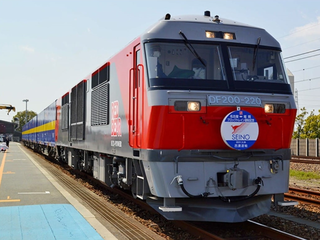
Above is the stock image that was sent out with all media online. I was very surprised to see a DF200 up-front... so-much-so that I thought there'd be a chance one would run the service! The media releases indicated that the train wouldn't be full of Kangaroo-only containers and that there'd be space available for other operators to hitch a ride.
| Location | Northbound | Southbound (read upwards) |
|---|---|---|
| Service | 5051 | |
| Nagoya Terminal | 2212 | 1823 |
| Inazawa | 2229-2237 | 1721-1804 |
| Gifu | 2258-0007 | 1559-1655 |
| Suita | 0201-0204 | 1245-1250 |
| Kobe | 0238 | 1210 |
| Himeji | 0309 | 1135 |
| Okayama | 0423-0432 | 0911-0957 |
| Hiroshima | 0646-0649 | 0554-0601 |
| Iwakuni | 0734 | |
| Shinanyo | 0850 | 0409 |
| Hatabu | 1028-1040 | 0219-0244 |
| Kita-kyushu | 1056-1106 | 0125-0202 |
| Fukuoka Terminal | 1247 | 0022 |
| Service | 5050 |
Westbound Service
The first train to leave was the westbound service from Nagoya to Fukuoka. At 2012 on March the 29th, the service departed and passed the Nagoya Station Camera not long after.
As you're watching the start of the video, you might be ready to tell me that it's "not the right train!"... but as the consist keeps rolling through the camera, you'll see that the Kangaroo-liveried containers are all piled on the rear. As mentioned above, there was always going to be spare room on the rake of flat wagons and the company was very happy to accommodate other operator's containers.
After travelling west, it then passed the Mukomachi Live Cam with quite a few more Kangaroo containers on-board!
From here, the Shin-Osaka cam picked it up, but it there was less-than-zero visibility. Unfortunately, there's no other cameras to the west to capture the action!
Eastbound Service
Due to this limited visibility out west, the first spot the train was seen was the Shin-Osaka Live Cam. The eastbound service seems to have at-least half a loading of Kanga-tainers.
After a stop-over at Suita, the train passed the Mukomachi Live Cam on time.
And then finally, back through the Nagoya Station Camera.
Looking forward to seeing these in real life... at some point... in the distant future.
Apple eMate 300 – Battery Refurb
Whilst fixing the hinges in my eMate 300, I noticed that there were also links to replacing the batteries. That link shows how to replace with proper cells, but it turns out that you could also use a battery holder.
I bought a full kit of bits to do the latter, but then realised that the installation required hacking out the existing cage for the battery. Not wanting to do this, I fell back to the soldering idea and wished I'd bought batteries with solder tabs instead of just standard AA-style cells.
Anatomy of a Battery Pack
The eMate 300 battery back has a socket with 5 pins/4 wires, a thermistor, 4 cells and a temperature switch at the far end. When replacing the cells, remember to keep everything but the actual cells themselves.
Peel the plastic off and then de-solder or cut all contacts. And keep the temperature switch!
Solder everything back together in the same order...
And then jam it back in the plastic case that it all came in...
If you're in luck...
You'll have a charging battery!
Testing it...
There doesn't seem to be an SSH client for the Newton (although people have tried), so I thought I'd go for Telnet. It seems easy to do over a serial cable, but I want to do it over Wifi! Thankfully there's the PT100v1.1 Client available over at United Network of Newton Archives.
Installing this got me a prompt... but a swift disconnection when trying to log in. But, the battery is still showing full charge after minimal use over two days! Win.
Fukuyama Rail Express でGO!
The Fukuyama Rail Express is an express rail-freight service run by Fukuyama Transporting Co, Ltd. Regarding rail-freight, they previously only operated a service from East-Fukuyama to Tokyo.
Here's a shot of that service from my travels in 2019, running past Shin-Osaka Station behind an EF66.
As of yesterday, a new service has been innaugurated from Ajikawaguchi (Osaka) to Morioka!

How bad is my photoshop? Note that the services only run on weekdays.
| Location | Northbound | Southbound (read upwards) |
|---|---|---|
| Service | 58 | |
| Ajikawaguchi | 2208 | 1600 |
| Suita | 2227-2231 | 1516-1528 |
| Gifu | 0023 | 1257 |
| Inazawa | 0038-0040 | 1229-1234 |
| Kasadera | 1206 | |
| Nishi-Hamamatsu | 0200 | 1025 |
| Shizuoka | 0259-0301 | 0902-0910 |
| Yoshiwara | 0826 | |
| Numazu | 0337 | 0747-0749 |
| Sagami | 0421 | 0656 |
| Yokohama | 0449 | 0629 |
| Shin-Tsurumi | 0505 (arrive) | 0615 (depart) |
| Loco swap and service change to 61 | Loco swap and service change to 59 | |
| Shin-Tsurumi | 0541 (depart) | 0541 (arrive) |
| Kajigaya | 0551 | 0532 |
| Niiza | 0625 | 0502 |
| Omiya | 0642 | 0449 |
| Utsunomiya | 0745 | 0351 |
| Kuroiso | 0838-0842 | 0259-0303 |
| Koriyama Terminal | 0931-0954 | 0007-0158 |
| Iwanuma | 2234 | |
| Sendai | 1147-1207 | 2141-2215 |
| Higashi-Sendai | 1217 | 2134 |
| Kogota | 2051 | |
| Morioka | 1433 | 1908 |
| Service | 60 |
Thanks to Japan's love of live-cameras, I was able to follow the service in both directions. Actually, as I start to write this post, both trains are still running both north and south. Anyway, let's rewind and check out what happened.
Light Engine to Ajikawaguchi
The northbound service started at Ajikawaguchi, just next to Universal Studios Japan in Osaka. To get the rake of beautifully-shiny containers out of the port, an engine was needed. EF210-156 was sourced from Suita and sent to Ajikawaguchi at around 1930 on the 23rd of March, 2021. Here it is passing the Shin-Osaka Live Cam.
It then passed the webcam near Fukushima Station.
Ajikawaguchi to Morioka
With the loco in place, the next step was to run the service! The consist ended up passing the Fukushima Camera around ~4 minutes behind schedule thanks to a late-running Haruka Airport Express.
Back to the Shin-Osaka Live Cam, it was nearly impossible to see it pass... but the audio is awesome in the night air!
Next up, it passed the Mukomachi Live Cam, amongst all the other freights and services.
A while later, it passed through Nagoya Station. Note the Shinkansen track vehicles working away also. That's a huge Tamper!
There's a great cam between Fuji and Shizuoka (which I've discussed before, recording times) and the train was seen passing through.
As that the train took the Niiza route through Tokyo, we couldn't see it on the Akabane or Shinjuku Cameras. Therefore the next and final camera was the Omiya Camera. The EH500 would've been swapped on at Shin-Tsurumi.
And that was it for the northbound. Congratulations Fukuyama Transport! Fortunately, we still had the southbound to stalk.
Morioka to Ajikawaguchi
The southbound left Morioka on the same night at 1908. It therefore passed the Omiya Camera before the northbound at around ~0450.
Whilst waiting for it at the Fuji cam, the northbound original Fukuyama Rail Express from East-Fukuyama passed by!
A little while later, the southbound was seen passing.
Next up was Nagoya Station.
And another guest came through an hour later...
And then again at Mukomachi Live Cam, right up the back, top-right, look really close!...
And since we're still waiting for the Fukuyama Rail Express to get to Mukomachi, here's Doctor Yellow passing Torikai to Shin-Osaka.
Whilst 'waiting at Mukomachi Live Cam', an EF65 passed towing a DD200!
And then, the main event at Mukomachi Live Cam.
Back through the Shin-Osaka Live Cam.
Through the Southern-Side Shin-Osaka Cam, one minute earlier if you believe system clocks... Also, this camera was down the previous evening when the inaugural service ran...
And then the final shot of the day! Past the Osaka Loop Line at Fukushima.
And that's a wrap!
Power Mac 6100/66 DOS Compatible – MIDI Out
After building the 'hydra cable' for this DOS Compatible machine, I quickly found out that the Joystick port could not be used for MIDI input/output. There were numerous hints online, and they all resulted to the fact that we'd need to solder a pin on the Vibra16 IC to get midi to the port. Here's the module removed from the DOS card. The CT2501 IC nearly takes up the entire board.
I was able to re-wire all of the below as I created my own hydra cable. I wouldn't suggest trying to modify an off-the-shelf cable as they're a sealed unit and have many pins incorrectly wired at the joystick-port-end.
Determining the correct pin
I'd asked online for help from someone who'd already worked out the solution, but hadn't received a quick answer. After rummaging through my junk boxes, I realised I didn't have a card with the correct CT2501 chipset, so I asked a few friends also. No one had the exact model required, so I considered purchasing one on eBay. They were averaging about one-hundred-dwollar shipped, so I decided to try and find high resolution photos online instead.
It turns out that dosdays has a fantastic library of information on the SB16. Included are high-enough-res photos of the rear of the board that allowed me to easily trace pin 12 (MIDI OUT) back to the CT2501 IC. Pin 15 (MIDI IN) wasn't so easy as it disappears under the 74-series IC in the bottom left of the top-side of the board. Fortunately, my main goal was to just get DOOM II throwing MIDI out to my SC-88.
After sitting in Paint.NET for a while, tracing traces, I came to the conclusion that MIDI OUT was Pin 30 of CT2501. In the pictures above, I've traced this in RED on the underside-shot of the board and YELLOW on the zoomed in CPU picture. MIDI IN is traced in BLUE on the underside-shot, but then disappears on the top half under the IC. Images from the web don't provide enough detail to allow me to continue the search! I was happy with just MIDI OUT, so I then started the quick hack-job to solder on a test wire...
In no time at all, DOOM II was outputting its soundtrack into my headphones.
Usually I'd pipe the audio-out from the SC-88 back into the soundcard of the computer that it was connected to, but that's not an option here with the Power Mac 6100 as it only has Microphone In! Oh wait, can I also wire-up Line-In for the DOS Card? I don't think that'd be as straight-forward as I'm sure there'd be a DAC and other components on the path.
External Connections
The port at the back only needed to be one wire, so I initially used an RCA socket.
I then realised I had no spare RCA plugs on-hand, so I switched the socket to a 3.5mm mono audio jack. This looked nicer anyway.
From here, a headphone cable was wired through with one of the channels running to pin 12 on the joystick port. This was then plugged into the SC-88 and DOOM II WAS PLAYED AT FULL VOLUME!
Power Mac 6100/66 DOS Compatible – MIDI
I couldn't resist this over-sized-pizza-box when I saw it on Facebook Marketplace. I never really check that area of the web, as the interaction mechanism is too loose... half the time you never even get a response from sellers and it doesn't feel real-time enough to trust if anything is actually available. Anyway, I threw a curve-ball offer and the seller responded (6 hours later)! The unit was picked up in short time, well actually... I had to wait for Victoria's 5-day lockdown to end. Yes, that was a while ago! It's been sitting in the junk room waiting for a video adapter cable thanks to it's HDI-45 video plug.
It's a beautiful unit. A much larger pizza-box than the LCs and it's even DOS Compatible!
Period-Correct Screen
By the time the video adapter cable came from America, I was ready to test the unit. I'd actually recently picked up a Trinitron monitor from the tip shop and it also needed testing! After a good sanitisation all round, everything was plugged together. To connect the Mac to the Monitor, I needed the HDI-45 to DB-15 adapter and then another DB-15 to DE-15 to get to VGA standards. With everything connected I got nothing... just a black screen... but I did get a startup bong! Myoldmac has a great reference on the video adapter settings and I had to use this as my adapter seems to have lost its packaging and the settings sticker on the actual unit. After a miriad of tests, the correct answer was to have 'separate sync' configured.
Ok, with a picture showing, I could now configure resolutions... only up to 832x624? What gives? Oh, This machine has 640kb of non-upgradeable VRAM limiting my choices. There's a good write-up here describing its system limitations. Turns out the AV Model has a separate card with 2MB allowing more resolutions on an external monitor. That wont work for me though... I have a DOS card in there!
MIDI By Roland
Before we get to DOS, let's just get my external SC-88 going. It's got a serial connection and I've always wanted to test it. Firstly, grab a game that'll support it and get that installed. Actually, there're too many options to choose from there. For fun, I'll load up DOOM II as, well, it has the easiest gameplay and a great soundtrack!
Grab a standard serial cable, make sure you choose a port that's free (i.e. not in-use by AppleTalk as you won't get a single message and it'll just not-work) and plug it all together. Make sure the SC-88 is set to "Mac" and that it has been power cycled since that switch was changed. Then power up the Macintosh. Don't expect anything to be hot-pluggable! But even then, nothing would be visible in the Quicktime Settings.
At this point in time, you can look over here for hints and then here for cable wiring and then here for the Roland manual and keep guessing why that Quicktime panel doesn't work... but don't bother.
No amount of cable-foolery got the basic Quicktime Installation to enable the General Midi checken-boxen. Instead, I software-foolery'd around until a version of OMS both extracted and installed. Note, if you've just installed MacOS, do not use the version of StuffIt from the Internet Utilities folder. It's archaic and will fail to extract things. Make sure you get a recent version installed first!
I need to discuss the middle shot above. It's telling you that, if AppleTalk is enabled, one of your Serial ports might be in use and the CPU will also be under pressure. Fortunately, our AppleTalk config is over Ethernet, so no Serial ports are in use! Is this software version for Macs with zero Ethernet capabilities? Eek... Anyway... auto-detect away!
Haha.. it found 16 Roland SC-88s... If I was a rich man? Must download some Beatles. After this, many duplicates were cleaned up until there was only one. From there, I scrolled down to check the other port...
The Yamaha MU80 didn't fair as well... it itself threw an ILLEGAL COMMAND error and the software decided it was a shitty Modem.
So.. just force it in the settings...
And then try again...
Music! Doom II sounded amazing.
DOS Compatible
PC Setup was already installed on the hideously-themed OS. I tried to boot it up, but the screen just went black! Turns out that unlike the previous Power Mac 7220, this one needed an external cable to route the video through. Googlin' around, there were a few options/schematics, but unfortunately this specific Power Mac had the HDI-45 Video port and therefore needed a hydra cable containing a different pinout. Thanks to the internet though, someone has already done the build and the pinout was available (and more over here). Here it is again for safe-keeping:
| Connector on DOS card 26-pin Male on cable | Video out on 6100 15-pin Male on cable | Video to monitor 15-pin Female on cable | Joystick connector 15-pin Female on cable |
|---|---|---|---|
| 1 | 2 (Button 1) | ||
| 2 | 3 (J1 - X) | ||
| 3 | 6 (J1 - Y) | ||
| 4 | 9 (Blue) | 9 (Blue) | |
| 5 | 5 (Green) | 5 (Green) | |
| 6 | 3 (CSYNC) | ||
| 7 | 14 (HSYNCGND) | ||
| 8 | 15 (HSYNC) | ||
| 9 | 4 (SENSE0) | 4 (SENSE0) | |
| 10 | 1,8,9,15 (+5V DC) | ||
| 11 | 11 (J2 - X) | ||
| 12 | 13 (J2 - Y) | ||
| 13 | 7 (Button 2) | ||
| 14 | 1,6,11,13 (grounds) | 1,6,11,13,14 (grounds) | 4,5,12 (grounds) |
| 15 | 1,6,11,13,14 (grounds) | 4,5,12 (grounds) | |
| 16 | 15 (HSYNC) | ||
| 17 | 12 (VSYNC) | ||
| 18 | 7 (SENSE1) | 7 (SENSE1) | |
| 19 | 10 (Button 4) | ||
| 20 | 1,6,11,13 (grounds) | 1,6,11,13,14 (grounds) | 4,5,12 (grounds) |
| 21 | 14 (Button 3) | ||
| 22 | 2 (Red) | 2 (Red) | |
| 23 | 1,6,11,13 (grounds) | 1,6,11,13,14 (grounds) | 4,5,12 (grounds) |
| 24 | 12 (VSYNC) | ||
| 25 | 3 (CSYNC) | ||
| 26 | 10 (SENSE2) | 10 (SENSE2) |
Each of the three plugs coming off the main plug need 13 wires each! I don't think I've ever had a standard 'round' cable in my arsenal that had more than 8 wires. Maybe I should trash a printer cable? Maybe I'll just heat-strink single-strands? If I cut the heat-strink up enough, it can 'telescope' down when I'm soldering and then I can slide the pieces up, bit-by-bit? Looking a bit like bamboo? It won't be too flexible though!
I started chopping up wires to use for the individual pins... until it occurred to me that pins were shared across all three secondary plugs. How does one share a wire succesfully? I'd actually need to construct 1-to-2/3 wires that split out into the differing plugs. At the final plug end, they can bridge all the pins they need to, but they need to get there first, without causing wire bridges 'outside' the initial plug housing.
So, with this in mind, I twisted two or three wires together where the ground feed needed to be distributed. I even used resistor legs to shift the major solder blob away from the plug solder pins.
Somewhere around the middle photo above I went slightly insane... and slept. Soldering and routing that many wires was a nightmare!
IT WAS EVEN WORSE ONCE A SINGLE END PLUG WAS ON!
But finally, a hydra-sorta-styled cable was assembled. All wiring was double-checked and then it was plugged together:
No way. It worked. I re-loaded the DOS image hard disk file from the original installation of Mac OS and found a copy of Win95B with an app that seemed to be a collection of "The Age" articles. Who-the-fxxx would want to have a source of that trash?
Unfortunately, it seems that all the data was on CD! So I shut it down.
Shiiiit.. haven't seen that in a LOOOOOONG while. I then tried to shut down the actual Macintosh... after Apple-Return switching back to MacOS...
What dat? Does this thing have an actual physical clicky power switch? i.e. non-atx-style soft power off? I pushed it and it did indeed click! I never noticed when turning it on!
MIDI via the DOS Joystick Port?
I was really hoping to hook up my Roland SC-88 to the joystick port, but no go. A quick google of pinouts shows that MIDI TX/RX signals are on pins 12 and 15 and these are tied to +5V and GND, which means it's actually REALLY DANGEROUS to hook up any MIDI device to this joystick-only port. Actually, I blab a lot on here, so let's just re-make that point...
Power Mac 6100/66 DOS Compatible Card Warning
Looking at the cable pinout table further above, it shows that we also don't have any spare pins on the 26-pin plug from the DOS card to squeeze MIDI through, so no wonder they prioritised video over the game port. Interestingly though, couldn't they have possibly spared two of those ground wires to pass MIDI data through?
It then occurred to me that we might be able to route the MIDI data through the Macintosh' Serial Port. To do this, I first connected my SC-88 (which has a very convenient Macintosh Serial Port on it!) to the Printer port and configured PC Setup to route COM1 to this.
From here, I downloaded and installed softmpu. This driver loads into RAM and intercepts all calls to the IO of the MPU on the Sound Card. The DOS Card fully supports the MPU, it's just that the output pins are literally un-wired! So, with the virtual tap, we can send the MIDI data out to COM1 instead, which is then virtually connected to the Macintosh Printer Port which is then hard-wired to the SC-88!
But it didn't work... softmpu just froze up the DOS side whenever executed.
Can we wire up the MIDI Port?
I then did a bit of Googlin' about those missing traces from the CT2501 Vibra 16 chipset. It seems that many have discussed it before, but each time it's ended in silence. Macintosh Garden's Comment Thread even tells me that it would've never worked and half of me wished I'd read that at the start as I probably would've not even bothered to wire up the port!
In 2019, BaldGoldEagle brought up the exact topic again on Vogons and got a good amount of detail, even after a direct bit of abuse from someone who didn't quite listen at the start (yeah, I'm talkin'bout you derSammler). The basic answer was to find a PC soundcard that has the same chipset (CT2260, CT2810, PB3110, CT3110, CT3930) and trace the pins to the port to work out what we'd need to build. The thread ended with a user offering to do so, but then the usual silence... I've just replied to see if anything came about!
A little more googlin' brought up a beautiful post dishing out on all of the DOS cards as they were built. Initially, the Houdini cards were mentioned as supporting MIDI! That was quickly corrected in the replies and the same result was reached: crickets.
I'll post again about MIDI once I've worked on it all a little more. (This now works! More information here!)
Arcade1Up Hacking
Thanks to some heavy coin-pusher usage at a local amusement center, this unit was 'won' and dragged home on the train. Pretty funny watching everyone watching me carrying a box'o'arcade machine on public transport!
In no time the machine was upright and SF2 was being played. All very nostalgic from both childhood and ... exactly 10 years and 10 days ago when I built MAME controllers from MS Keyboards.
The unit came with 3 versions of SF2, but it was never my intention to keep it stock. The unit itself would provide a perfect base to build a fully-fledged arcade machine with all the games of my childhood!
The Base Hardware
The unit has an AllWinner ARM SOC built into a case mounted behind the screen. It's a tiny board that wont be easy to flash or extend. This actually means that there's a ridiculous amount of free space in the bottom of the unit as the actual electronics are tiny.
The ARM board would be difficult to re-flash and would also be limited with storage, so the decision was quickly made to replace the guts. Fortunately I could still use the screen and controls.
The New Hardware and Software
To use the screen, I had to purchase a controller board. It seems that the Arcade1Up guys have used a screen that's popular in other actual LCD monitors and therefore the boards are easy to come by. I found one on eBay... just search for LCD Controller Board For HSD190MEN4 M170EN06 17 inch D2K4. Pretty cryptic, but it's the model of the LCD.
With this unit swapped in, I now had VGA/HDMI/DVI access to the LCD! From here, I grabbed the nearest motherboard which happened to be an AMD Sempron X2 with 16GB RAM. I initially tried to use a GTX970 as well, but the compatibility with retro Linux distros wasn't up to scratch and therefore just stuck with the onboard video.
The controllers were wired in with USB Joystick Interfaces from Jaycar. They both were really plug-and-play and it meant I just had to unplug the controllers from the current distribution board and plug them into this one.
Choosing an OS can be difficult as there are a few great options: Lakka and Recalbox. I can't remember why I didn't enjoy Recalbox.
Slow Boot
I had initially installed a spare 1TB SSD, but found out quickly that it was unhealthy. I hadn't guessed it was the issue to start with, until I enabled SSH and reviewed dmesg.
login as: root
root@lakka's password:
###########################################
# Lakka - The DIY retro emulation console #
# ...... visit http://www.lakka.tv ...... #
###########################################

Lakka (official): 2.3.2 (Generic.x86_64)
Lakka:~ # dmesg
[    0.000000] BRK [0x03cf3000, 0x03cf3fff] PGTABLE
[    0.000000] BRK [0x03cf4000, 0x03cf4fff] PGTABLE
[    0.000000] BRK [0x03cf5000, 0x03cf5fff] PGTABLE
[    0.000000] BRK [0x03cf6000, 0x03cf6fff] PGTABLE
[    0.000000] ACPI: Early table checksum verification disabled
[    0.000000] ACPI: RSDP 0x00000000000F0450 000024 (v02 ALASKA)
[    0.000000] ACPI: XSDT 0x00000000BFB18070 00005C (v01 ALASKA A M I    01072009 AMI  00010013)
[    0.000000] ACPI: FACP 0x00000000BFB1CD28 0000F4 (v04 ALASKA A M I    01072009 AMI  00010013)
[    0.000000] ACPI BIOS Warning (bug): Optional FADT field Pm2ControlBlock has valid Length but zero Address: 0x0000000000000000/0x1 (20170119/tbfadt-649)
[    0.000000] ACPI: DSDT 0x00000000BFB18158 004BC9 (v02 ALASKA A M I    00000000 INTL 20051117)
[    0.000000] ACPI: FACS 0x00000000BFB54F80 000040
[    0.000000] ACPI: APIC 0x00000000BFB1CE20 000092 (v03 ALASKA A M I    01072009 AMI  00010013)
[    0.000000] ACPI: MCFG 0x00000000BFB1CEB8 00003C (v01 ALASKA A M I    01072009 MSFT 00010013)
[    0.000000] ACPI: AAFT 0x00000000BFB1CEF8 00003A (v01 ALASKA OEMAAFT  01072009 MSFT 00000097)
[    0.000000] ACPI: MCFG 0x00000000BFB1CF38 00003C (v01 ALASKA A M I    01072009 MSFT 00000097)
[    0.000000] ACPI: HPET 0x00000000BFB1CF78 000038 (v01 ALASKA A M I    01072009 AMI  00000004)
[    0.000000] ACPI: SSDT 0x00000000BFB1CFB0 0008BC (v01 AMD    POWERNOW 00000001 AMD  00000001)
[    0.000000] ACPI: Local APIC address 0xfee00000
[    0.000000] No NUMA configuration found
[    0.000000] Faking a node at [mem 0x0000000000000000-0x000000012fffffff]
[    0.000000] NODE_DATA(0) allocated [mem 0x12fff9000-0x12fffcfff]
[    0.000000] Zone ranges:
[    0.000000]   DMA      [mem 0x0000000000001000-0x0000000000ffffff]
[    0.000000]   DMA32    [mem 0x0000000001000000-0x00000000ffffffff]
[    0.000000]   Normal   [mem 0x0000000100000000-0x000000012fffffff]
[    0.000000] Movable zone start for each node
[    0.000000] Early memory node ranges
[    0.000000]   node   0: [mem 0x0000000000001000-0x000000000009dfff]
[    0.000000]   node   0: [mem 0x0000000000100000-0x00000000bfacbfff]
[    0.000000]   node   0: [mem 0x00000000bfd84000-0x00000000bfefffff]
[    0.000000]   node   0: [mem 0x0000000100001000-0x000000012fffffff]
[    0.000000] Initmem setup node 0 [mem 0x0000000000001000-0x000000012fffffff]
[    0.000000] On node 0 totalpages: 981988
[    0.000000]   DMA zone: 64 pages used for memmap
[    0.000000]   DMA zone: 21 pages reserved
[    0.000000]   DMA zone: 3997 pages, LIFO batch:0
[    0.000000]   DMA32 zone: 12210 pages used for memmap
[    0.000000]   DMA32 zone: 781384 pages, LIFO batch:31
[    0.000000]   Normal zone: 3072 pages used for memmap
[    0.000000]   Normal zone: 196607 pages, LIFO batch:31
[    0.000000] ACPI: PM-Timer IO Port: 0x808
[    0.000000] ACPI: Local APIC address 0xfee00000
[    0.000000] ACPI: LAPIC_NMI (acpi_id[0xff] high edge lint[0x1])
[    0.000000] IOAPIC[0]: apic_id 0, version 33, address 0xfec00000, GSI 0-23
[    0.000000] ACPI: INT_SRC_OVR (bus 0 bus_irq 0 global_irq 2 dfl dfl)
[    0.000000] ACPI: INT_SRC_OVR (bus 0 bus_irq 9 global_irq 9 low level)
[    0.000000] ACPI: IRQ0 used by override.
[    0.000000] ACPI: IRQ9 used by override.
[    0.000000] Using ACPI (MADT) for SMP configuration information
[    0.000000] ACPI: HPET id: 0xffffffff base: 0xfed00000
[    0.000000] smpboot: Allowing 8 CPUs, 4 hotplug CPUs
[    0.000000] e820: [mem 0xbff00000-0xfebfffff] available for PCI devices
[    0.000000] Booting paravirtualized kernel on bare hardware
[    0.000000] clocksource: refined-jiffies: mask: 0xffffffff max_cycles: 0xffffffff, max_idle_ns: 1910969940391419 ns
[    0.000000] setup_percpu: NR_CPUS:16 nr_cpumask_bits:16 nr_cpu_ids:8 nr_node_ids:1
[    0.000000] percpu: Embedded 36 pages/cpu @ffff88012fc00000 s107904 r8192 d31360 u262144
[    0.000000] pcpu-alloc: s107904 r8192 d31360 u262144 alloc=1*2097152
[    0.000000] pcpu-alloc: [0] 0 1 2 3 4 5 6 7
[    0.000000] Built 1 zonelists in Node order, mobility grouping on.  Total pages: 966621
[    0.000000] Policy zone: Normal
[    0.000000] Kernel command line: root=/dev/ram0 rdinit=/init usbcore.autosuspend=-1 BOOT_IMAGE=/KERNEL boot=LABEL=System disk=LABEL=Storage  quiet vt.global_cursor_default=0 loglevel=2
[    0.000000] PID hash table entries: 4096 (order: 3, 32768 bytes)
[    0.000000] AGP: Checking aperture...
[    0.000000] AGP: No AGP bridge found
[    0.000000] AGP: Node 0: aperture [bus addr 0xfbf6000000-0xfbf7ffffff] (32MB)
[    0.000000] Aperture beyond 4GB. Ignoring.
[    0.000000] AGP: Your BIOS doesn't leave an aperture memory hole
[    0.000000] AGP: Please enable the IOMMU option in the BIOS setup
[    0.000000] AGP: This costs you 64MB of RAM
[    0.000000] AGP: Mapping aperture over RAM [mem 0xb4000000-0xb7ffffff] (65536KB)
[    0.000000] Memory: 3687652K/3927952K available (12780K kernel code, 1042K rwdata, 25412K rodata, 3464K init, 504K bss, 240300K reserved, 0K cma-reserved)
[    0.000000] SLUB: HWalign=64, Order=0-3, MinObjects=0, CPUs=8, Nodes=1
[    0.000000] Preemptible hierarchical RCU implementation.
[    0.000000]  Build-time adjustment of leaf fanout to 64.
[    0.000000]  RCU restricting CPUs from NR_CPUS=16 to nr_cpu_ids=8.
[    0.000000] RCU: Adjusting geometry for rcu_fanout_leaf=64, nr_cpu_ids=8
[    0.000000] NR_IRQS:4352 nr_irqs:488 16
[    0.000000] Console: colour VGA+ 80x25
[    0.000000] console [tty0] enabled
[    0.000000] clocksource: hpet: mask: 0xffffffff max_cycles: 0xffffffff, max_idle_ns: 133484873504 ns
[    0.000000] hpet clockevent registered
[    0.000000] tsc: Fast TSC calibration using PIT
[    0.001000] tsc: Detected 3013.189 MHz processor
[    0.001000] Calibrating delay loop (skipped), value calculated using timer frequency.. 6026.37 BogoMIPS (lpj=3013189)
[    0.001000] pid_max: default: 32768 minimum: 301
[    0.001000] ACPI: Core revision 20170119
[    0.002751] ACPI: 2 ACPI AML tables successfully acquired and loaded
[    0.003214] Dentry cache hash table entries: 524288 (order: 11, 8388608 bytes)
[    0.005267] Inode-cache hash table entries: 262144 (order: 9, 2097152 bytes)
[    0.005794] Mount-cache hash table entries: 8192 (order: 4, 65536 bytes)
[    0.005798] Mountpoint-cache hash table entries: 8192 (order: 4, 65536 bytes)
[    0.006004] CPU: Physical Processor ID: 0
[    0.006004] CPU: Processor Core ID: 0
[    0.006006] Last level iTLB entries: 4KB 512, 2MB 16, 4MB 8
[    0.006007] Last level dTLB entries: 4KB 512, 2MB 128, 4MB 64, 1GB 0
[    0.006093] Freeing SMP alternatives memory: 40K
[    0.007078] smpboot: Max logical packages: 2
[    0.007443] ..TIMER: vector=0x30 apic1=0 pin1=2 apic2=-1 pin2=-1
[    0.018000] smpboot: CPU0: AMD Phenom(tm) II X4 945 Processor (family: 0x10, model: 0x4, stepping: 0x2)
[    0.021022] Performance Events: AMD PMU driver.
[    0.021027] ... version:                0
[    0.021028] ... bit width:              48
[    0.021028] ... generic registers:      4
[    0.021029] ... value mask:             0000ffffffffffff
[    0.021029] ... max period:             00007fffffffffff
[    0.021030] ... fixed-purpose events:   0
[    0.021031] ... event mask:             000000000000000f
[    0.033080] NMI watchdog: enabled on all CPUs, permanently consumes one hw-PMU counter.
[    0.035016] smp: Bringing up secondary CPUs ...
[    0.046024] x86: Booting SMP configuration:
[    0.046025] .... node  #0, CPUs:      #1 #2 #3
[    0.251031] smp: Brought up 1 node, 4 CPUs
[    0.251031] smpboot: Total of 4 processors activated (24103.72 BogoMIPS)
[    0.252078] sched_clock: Marking stable (252000000, 0)->(361237982, -109237982)
[    0.252339] devtmpfs: initialized
[    0.252739] PM: Registering ACPI NVS region [mem 0xbfacc000-0xbfb1dfff] (335872 bytes)
[    0.252744] PM: Registering ACPI NVS region [mem 0xbfb52000-0xbfb59fff] (32768 bytes)
[    0.252745] PM: Registering ACPI NVS region [mem 0xbfb81000-0xbfd83fff] (2109440 bytes)
[    0.252825] clocksource: jiffies: mask: 0xffffffff max_cycles: 0xffffffff, max_idle_ns: 1911260446275000 ns
[    0.252856] futex hash table entries: 2048 (order: 6, 262144 bytes)
[    0.252927] xor: measuring software checksum speed
[    0.262649]    prefetch64-sse: 13896.000 MB/sec
[    0.272663]    generic_sse: 13184.000 MB/sec
[    0.272666] xor: using function: prefetch64-sse (13896.000 MB/sec)
[    0.272672] pinctrl core: initialized pinctrl subsystem
[    0.272890] NET: Registered protocol family 16
[    0.273193] cpuidle: using governor ladder
[    0.273229] cpuidle: using governor menu
[    0.273232] PCCT header not found.
[    0.273236] node 0 link 0: io port [c000, ffff]
[    0.273238] TOM: 00000000d0000000 aka 3328M
[    0.273239] Fam 10h mmconf [mem 0xe0000000-0xefffffff]
[    0.273241] node 0 link 0: mmio [d0000000, efffffff] ==> [d0000000, dfffffff]
[    0.273243] node 0 link 0: mmio [f0000000, fe4fffff]
[    0.273244] node 0 link 0: mmio [fe500000, fe6fffff]
[    0.273246] node 0 link 0: mmio [fe700000, febfffff]
[    0.273247] node 0 link 0: mmio [fec00000, fffeffff]
[    0.273248] node 0 link 0: mmio [ffff0000, ffffffff]
[    0.273249] TOM2: 0000000130000000 aka 4864M
[    0.273250] bus: [bus 00-1f] on node 0 link 0
[    0.273251] bus: 00 [io  0x0000-0xffff]
[    0.273251] bus: 00 [mem 0xd0000000-0xdfffffff]
[    0.273252] bus: 00 [mem 0xf0000000-0xffffffff]
[    0.273253] bus: 00 [mem 0x130000000-0xfcffffffff]
[    0.273389] ACPI: bus type PCI registered
[    0.273465] PCI: MMCONFIG for domain 0000 [bus 00-ff] at [mem 0xe0000000-0xefffffff] (base 0xe0000000)
[    0.273467] PCI: not using MMCONFIG
[    0.273468] PCI: Using configuration type 1 for base access
[    0.273468] PCI: Using configuration type 1 for extended access
[    0.294675] raid6: sse2x1   gen()  3851 MB/s
[    0.311663] raid6: sse2x1   xor()  4023 MB/s
[    0.328658] raid6: sse2x2   gen()  6687 MB/s
[    0.345652] raid6: sse2x2   xor()  6890 MB/s
[    0.362658] raid6: sse2x4   gen()  7949 MB/s
[    0.379655] raid6: sse2x4   xor()  3494 MB/s
[    0.379657] raid6: using algorithm sse2x4 gen() 7949 MB/s
[    0.379658] raid6: .... xor() 3494 MB/s, rmw enabled
[    0.379659] raid6: using intx1 recovery algorithm
[    0.379749] ACPI: Added _OSI(Module Device)
[    0.379750] ACPI: Added _OSI(Processor Device)
[    0.379751] ACPI: Added _OSI(3.0 _SCP Extensions)
[    0.379751] ACPI: Added _OSI(Processor Aggregator Device)
[    0.380050] ACPI: Executed 3 blocks of module-level executable AML code
[    0.383018] ACPI: Interpreter enabled
[    0.383038] ACPI: (supports S0 S1 S3 S5)
[    0.383040] ACPI: Using IOAPIC for interrupt routing
[    0.383184] PCI: MMCONFIG for domain 0000 [bus 00-ff] at [mem 0xe0000000-0xefffffff] (base 0xe0000000)
[    0.383223] PCI: MMCONFIG at [mem 0xe0000000-0xefffffff] reserved in ACPI motherboard resources
[    0.383234] PCI: Using host bridge windows from ACPI; if necessary, use "pci=nocrs" and report a bug
[    0.390118] ACPI: PCI Root Bridge [PCI0] (domain 0000 [bus 00-ff])
[    0.390123] acpi PNP0A03:00: _OSC: OS supports [ExtendedConfig ASPM ClockPM Segments MSI]
[    0.390127] acpi PNP0A03:00: _OSC failed (AE_NOT_FOUND); disabling ASPM
[    0.390236] acpi PNP0A03:00: ignoring host bridge window [mem 0x000c8000-0x000dffff window] (conflicts with Video ROM [mem 0x000c0000-0x000cedff])
[    0.390268] PCI host bridge to bus 0000:00
[    0.390270] pci_bus 0000:00: root bus resource [io  0x0000-0x0cf7 window]
[    0.390271] pci_bus 0000:00: root bus resource [io  0x0d00-0xffff window]
[    0.390272] pci_bus 0000:00: root bus resource [mem 0x000a0000-0x000bffff window]
[    0.390273] pci_bus 0000:00: root bus resource [mem 0xd0000000-0xffffffff window]
[    0.390275] pci_bus 0000:00: root bus resource [bus 00-ff]
[    0.390283] pci 0000:00:00.0: [1022:9601] type 00 class 0x060000
[    0.390392] pci 0000:00:01.0: [1849:9602] type 01 class 0x060400
[    0.390495] pci 0000:00:09.0: [1022:9608] type 01 class 0x060400
[    0.390528] pci 0000:00:09.0: PME# supported from D0 D3hot D3cold
[    0.390576] pci 0000:00:09.0: System wakeup disabled by ACPI
[    0.390614] pci 0000:00:0a.0: [1022:9609] type 01 class 0x060400
[    0.390646] pci 0000:00:0a.0: PME# supported from D0 D3hot D3cold
[    0.390705] pci 0000:00:0a.0: System wakeup disabled by ACPI
[    0.390753] pci 0000:00:11.0: [1002:4390] type 00 class 0x01018f
[    0.390768] pci 0000:00:11.0: reg 0x10: [io  0xf090-0xf097]
[    0.390776] pci 0000:00:11.0: reg 0x14: [io  0xf080-0xf083]
[    0.390784] pci 0000:00:11.0: reg 0x18: [io  0xf070-0xf077]
[    0.390792] pci 0000:00:11.0: reg 0x1c: [io  0xf060-0xf063]
[    0.390800] pci 0000:00:11.0: reg 0x20: [io  0xf050-0xf05f]
[    0.390808] pci 0000:00:11.0: reg 0x24: [mem 0xfeb0b000-0xfeb0b3ff]
[    0.390827] pci 0000:00:11.0: set SATA to AHCI mode
[    0.390928] pci 0000:00:12.0: [1002:4397] type 00 class 0x0c0310
[    0.390940] pci 0000:00:12.0: reg 0x10: [mem 0xfeb0a000-0xfeb0afff]
[    0.391038] pci 0000:00:12.0: System wakeup disabled by ACPI
[    0.391080] pci 0000:00:12.2: [1002:4396] type 00 class 0x0c0320
[    0.391095] pci 0000:00:12.2: reg 0x10: [mem 0xfeb09000-0xfeb090ff]
[    0.391165] pci 0000:00:12.2: supports D1 D2
[    0.391166] pci 0000:00:12.2: PME# supported from D0 D1 D2 D3hot
[    0.391217] pci 0000:00:12.2: System wakeup disabled by ACPI
[    0.391279] pci 0000:00:13.0: [1002:4397] type 00 class 0x0c0310
[    0.391290] pci 0000:00:13.0: reg 0x10: [mem 0xfeb08000-0xfeb08fff]
[    0.391386] pci 0000:00:13.0: System wakeup disabled by ACPI
[    0.391429] pci 0000:00:13.2: [1002:4396] type 00 class 0x0c0320
[    0.391443] pci 0000:00:13.2: reg 0x10: [mem 0xfeb07000-0xfeb070ff]
[    0.391513] pci 0000:00:13.2: supports D1 D2
[    0.391514] pci 0000:00:13.2: PME# supported from D0 D1 D2 D3hot
[    0.391563] pci 0000:00:13.2: System wakeup disabled by ACPI
[    0.391624] pci 0000:00:14.0: [1002:4385] type 00 class 0x0c0500
[    0.391803] pci 0000:00:14.1: [1002:439c] type 00 class 0x01018a
[    0.391814] pci 0000:00:14.1: reg 0x10: [io  0xf040-0xf047]
[    0.391822] pci 0000:00:14.1: reg 0x14: [io  0xf030-0xf033]
[    0.391830] pci 0000:00:14.1: reg 0x18: [io  0xf020-0xf027]
[    0.391838] pci 0000:00:14.1: reg 0x1c: [io  0xf010-0xf013]
[    0.391846] pci 0000:00:14.1: reg 0x20: [io  0xf000-0xf00f]
[    0.391863] pci 0000:00:14.1: legacy IDE quirk: reg 0x10: [io  0x01f0-0x01f7]
[    0.391864] pci 0000:00:14.1: legacy IDE quirk: reg 0x14: [io  0x03f6]
[    0.391865] pci 0000:00:14.1: legacy IDE quirk: reg 0x18: [io  0x0170-0x0177]
[    0.391866] pci 0000:00:14.1: legacy IDE quirk: reg 0x1c: [io  0x0376]
[    0.391986] pci 0000:00:14.2: [1002:4383] type 00 class 0x040300
[    0.392004] pci 0000:00:14.2: reg 0x10: [mem 0xfeb00000-0xfeb03fff 64bit]
[    0.392063] pci 0000:00:14.2: PME# supported from D0 D3hot D3cold
[    0.392111] pci 0000:00:14.2: System wakeup disabled by ACPI
[    0.392149] pci 0000:00:14.3: [1002:439d] type 00 class 0x060100
[    0.392287] pci 0000:00:14.4: [1002:4384] type 01 class 0x060401
[    0.392364] pci 0000:00:14.4: System wakeup disabled by ACPI
[    0.392424] pci 0000:00:14.5: [1002:4399] type 00 class 0x0c0310
[    0.392436] pci 0000:00:14.5: reg 0x10: [mem 0xfeb06000-0xfeb06fff]
[    0.392534] pci 0000:00:14.5: System wakeup disabled by ACPI
[    0.392578] pci 0000:00:15.0: [1002:43a0] type 01 class 0x060400
[    0.392644] pci 0000:00:15.0: supports D1 D2
[    0.392706] pci 0000:00:15.0: System wakeup disabled by ACPI
[    0.392748] pci 0000:00:15.1: [1002:43a1] type 01 class 0x060400
[    0.392815] pci 0000:00:15.1: supports D1 D2
[    0.392865] pci 0000:00:15.1: System wakeup disabled by ACPI
[    0.392938] pci 0000:00:16.0: [1002:4397] type 00 class 0x0c0310
[    0.392949] pci 0000:00:16.0: reg 0x10: [mem 0xfeb05000-0xfeb05fff]
[    0.393046] pci 0000:00:16.0: System wakeup disabled by ACPI
[    0.393089] pci 0000:00:16.2: [1002:4396] type 00 class 0x0c0320
[    0.393103] pci 0000:00:16.2: reg 0x10: [mem 0xfeb04000-0xfeb040ff]
[    0.393174] pci 0000:00:16.2: supports D1 D2
[    0.393175] pci 0000:00:16.2: PME# supported from D0 D1 D2 D3hot
[    0.393224] pci 0000:00:16.2: System wakeup disabled by ACPI
[    0.393277] pci 0000:00:18.0: [1022:1200] type 00 class 0x060000
[    0.393355] pci 0000:00:18.1: [1022:1201] type 00 class 0x060000
[    0.393430] pci 0000:00:18.2: [1022:1202] type 00 class 0x060000
[    0.393503] pci 0000:00:18.3: [1022:1203] type 00 class 0x060000
[    0.393579] pci 0000:00:18.4: [1022:1204] type 00 class 0x060000
[    0.393708] pci 0000:01:05.0: [1002:9714] type 00 class 0x030000
[    0.393715] pci 0000:01:05.0: reg 0x10: [mem 0xd0000000-0xdfffffff pref]
[    0.393718] pci 0000:01:05.0: reg 0x14: [io  0xe000-0xe0ff]
[    0.393722] pci 0000:01:05.0: reg 0x18: [mem 0xfe600000-0xfe60ffff]
[    0.393730] pci 0000:01:05.0: reg 0x24: [mem 0xfe500000-0xfe5fffff]
[    0.393748] pci 0000:01:05.0: supports D1 D2
[    0.393783] pci 0000:01:05.1: [1002:970f] type 00 class 0x040300
[    0.393789] pci 0000:01:05.1: reg 0x10: [mem 0xfe610000-0xfe613fff]
[    0.393818] pci 0000:01:05.1: supports D1 D2
[    0.393911] pci 0000:00:01.0: PCI bridge to [bus 01]
[    0.393914] pci 0000:00:01.0:   bridge window [io  0xe000-0xefff]
[    0.393916] pci 0000:00:01.0:   bridge window [mem 0xfe500000-0xfe6fffff]
[    0.393918] pci 0000:00:01.0:   bridge window [mem 0xd0000000-0xdfffffff 64bit pref]
[    0.393956] pci 0000:02:00.0: [1b6f:7023] type 00 class 0x0c0330
[    0.393971] pci 0000:02:00.0: reg 0x10: [mem 0xfea00000-0xfea07fff 64bit]
[    0.394043] pci 0000:02:00.0: supports D1 D2
[    0.394044] pci 0000:02:00.0: PME# supported from D0 D1 D2 D3hot D3cold
[    0.396723] pci 0000:00:09.0: PCI bridge to [bus 02]
[    0.396728] pci 0000:00:09.0:   bridge window [mem 0xfea00000-0xfeafffff]
[    0.396784] pci 0000:03:00.0: [1969:1083] type 00 class 0x020000
[    0.396805] pci 0000:03:00.0: reg 0x10: [mem 0xfe900000-0xfe93ffff 64bit]
[    0.396815] pci 0000:03:00.0: reg 0x18: [io  0xd000-0xd07f]
[    0.396908] pci 0000:03:00.0: PME# supported from D0 D1 D2 D3hot D3cold
[    0.399669] pci 0000:00:0a.0: PCI bridge to [bus 03]
[    0.399673] pci 0000:00:0a.0:   bridge window [io  0xd000-0xdfff]
[    0.399675] pci 0000:00:0a.0:   bridge window [mem 0xfe900000-0xfe9fffff]
[    0.399775] pci 0000:00:14.4: PCI bridge to [bus 04] (subtractive decode)
[    0.399783] pci 0000:00:14.4:   bridge window [io  0x0000-0x0cf7 window] (subtractive decode)
[    0.399784] pci 0000:00:14.4:   bridge window [io  0x0d00-0xffff window] (subtractive decode)
[    0.399785] pci 0000:00:14.4:   bridge window [mem 0x000a0000-0x000bffff window] (subtractive decode)
[    0.399786] pci 0000:00:14.4:   bridge window [mem 0xd0000000-0xffffffff window] (subtractive decode)
[    0.399846] pci 0000:05:00.0: [1106:3403] type 00 class 0x0c0010
[    0.399871] pci 0000:05:00.0: reg 0x10: [mem 0xfe800000-0xfe8007ff 64bit]
[    0.399883] pci 0000:05:00.0: reg 0x18: [io  0xc000-0xc0ff]
[    0.399991] pci 0000:05:00.0: supports D2
[    0.399992] pci 0000:05:00.0: PME# supported from D2 D3hot D3cold
[    0.402728] pci 0000:00:15.0: PCI bridge to [bus 05]
[    0.402734] pci 0000:00:15.0:   bridge window [io  0xc000-0xcfff]
[    0.402736] pci 0000:00:15.0:   bridge window [mem 0xfe800000-0xfe8fffff]
[    0.402807] pci 0000:06:00.0: [1b6f:7023] type 00 class 0x0c0330
[    0.402831] pci 0000:06:00.0: reg 0x10: [mem 0xfe700000-0xfe707fff 64bit]
[    0.402945] pci 0000:06:00.0: supports D1 D2
[    0.402946] pci 0000:06:00.0: PME# supported from D0 D1 D2 D3hot D3cold
[    0.405671] pci 0000:00:15.1: PCI bridge to [bus 06]
[    0.405682] pci 0000:00:15.1:   bridge window [mem 0xfe700000-0xfe7fffff]
[    0.406441] ACPI: PCI Interrupt Link [LNKA] (IRQs 10 11 14 15) *0
[    0.406501] ACPI: PCI Interrupt Link [LNKB] (IRQs 10 11 14 15) *0
[    0.406562] ACPI: PCI Interrupt Link [LNKC] (IRQs 10 11 14 15) *0
[    0.406623] ACPI: PCI Interrupt Link [LNKD] (IRQs 10 11 14 15) *0
[    0.406675] ACPI: PCI Interrupt Link [LNKE] (IRQs 10 11 14 15) *0
[    0.406728] ACPI: PCI Interrupt Link [LNKF] (IRQs 10 11 14 15) *0
[    0.406766] ACPI: PCI Interrupt Link [LNKG] (IRQs 10 11 14 15) *0
[    0.406804] ACPI: PCI Interrupt Link [LNKH] (IRQs 10 11 14 15) *0
[    0.407006] pci 0000:01:05.0: vgaarb: setting as boot VGA device
[    0.407008] pci 0000:01:05.0: vgaarb: VGA device added: decodes=io+mem,owns=io+mem,locks=none
[    0.407012] pci 0000:01:05.0: vgaarb: bridge control possible
[    0.407012] vgaarb: loaded
[    0.407074] SCSI subsystem initialized
[    0.407114] libata version 3.00 loaded.
[    0.407139] ACPI: bus type USB registered
[    0.407160] usbcore: registered new interface driver usbfs
[    0.407171] usbcore: registered new interface driver hub
[    0.407192] usbcore: registered new device driver usb
[    0.407216] pps_core: LinuxPPS API ver. 1 registered
[    0.407217] pps_core: Software ver. 5.3.6 - Copyright 2005-2007 Rodolfo Giometti <giometti@linux.it>
[    0.407219] PTP clock support registered
[    0.407278] wmi: Mapper loaded
[    0.407292] Advanced Linux Sound Architecture Driver Initialized.
[    0.407293] PCI: Using ACPI for IRQ routing
[    0.414819] PCI: pci_cache_line_size set to 64 bytes
[    0.414882] e820: reserve RAM buffer [mem 0x0009ec00-0x0009ffff]
[    0.414883] e820: reserve RAM buffer [mem 0xbfacc000-0xbfffffff]
[    0.414884] e820: reserve RAM buffer [mem 0xbff00000-0xbfffffff]
[    0.415150] clocksource: Switched to clocksource hpet
[    0.415214] FS-Cache: Loaded
[    0.415240] pnp: PnP ACPI init
[    0.415341] system 00:00: [mem 0xe0000000-0xefffffff] has been reserved
[    0.415345] system 00:00: Plug and Play ACPI device, IDs PNP0c01 (active)
[    0.415485] system 00:01: [mem 0xc0000000-0xcfffffff] has been reserved
[    0.415488] system 00:01: Plug and Play ACPI device, IDs PNP0c02 (active)
[    0.415772] system 00:02: [io  0x040b] has been reserved
[    0.415774] system 00:02: [io  0x04d6] has been reserved
[    0.415775] system 00:02: [io  0x0c00-0x0c01] has been reserved
[    0.415777] system 00:02: [io  0x0c14] has been reserved
[    0.415778] system 00:02: [io  0x0c50-0x0c51] has been reserved
[    0.415780] system 00:02: [io  0x0c52] has been reserved
[    0.415781] system 00:02: [io  0x0c6c] has been reserved
[    0.415783] system 00:02: [io  0x0c6f] has been reserved
[    0.415784] system 00:02: [io  0x0cd0-0x0cd1] has been reserved
[    0.415786] system 00:02: [io  0x0cd2-0x0cd3] has been reserved
[    0.415787] system 00:02: [io  0x0cd4-0x0cd5] has been reserved
[    0.415789] system 00:02: [io  0x0cd6-0x0cd7] has been reserved
[    0.415790] system 00:02: [io  0x0cd8-0x0cdf] has been reserved
[    0.415791] system 00:02: [io  0x0800-0x089f] has been reserved
[    0.415793] system 00:02: [io  0x0b20-0x0b3f] has been reserved
[    0.415795] system 00:02: [io  0x0900-0x090f] has been reserved
[    0.415796] system 00:02: [io  0x0910-0x091f] has been reserved
[    0.415799] system 00:02: [io  0xfe00-0xfefe] has been reserved
[    0.415801] system 00:02: [mem 0xfec00000-0xfec00fff] could not be reserved
[    0.415802] system 00:02: [mem 0xfee00000-0xfee00fff] has been reserved
[    0.415804] system 00:02: [mem 0xfed80000-0xfed8ffff] has been reserved
[    0.415806] system 00:02: [mem 0xfed61000-0xfed70fff] has been reserved
[    0.415807] system 00:02: [mem 0xfec10000-0xfec10fff] has been reserved
[    0.415809] system 00:02: [mem 0xfed00000-0xfed00fff] could not be reserved
[    0.415810] system 00:02: [mem 0xffc00000-0xffffffff] has been reserved
[    0.415813] system 00:02: Plug and Play ACPI device, IDs PNP0c02 (active)
[    0.415925] system 00:03: [io  0x0290-0x029f] has been reserved
[    0.415928] system 00:03: Plug and Play ACPI device, IDs PNP0c02 (active)
[    0.416118] pnp 00:04: Plug and Play ACPI device, IDs PNP0b00 (active)
[    0.416202] system 00:05: [io  0x04d0-0x04d1] has been reserved
[    0.416206] system 00:05: Plug and Play ACPI device, IDs PNP0c02 (active)
[    0.416279] system 00:06: Plug and Play ACPI device, IDs PNP0c02 (active)
[    0.416322] pnp 00:07: Plug and Play ACPI device, IDs PNP0303 PNP030b (active)
[    0.416371] pnp 00:08: Plug and Play ACPI device, IDs PNP0f03 PNP0f13 (active)
[    0.416594] pnp 00:09: [dma 0 disabled]
[    0.416640] pnp 00:09: Plug and Play ACPI device, IDs PNP0501 (active)
[    0.416914] pnp: PnP ACPI: found 10 devices
[    0.423939] clocksource: acpi_pm: mask: 0xffffff max_cycles: 0xffffff, max_idle_ns: 2085701024 ns
[    0.423976] pci 0000:00:01.0: PCI bridge to [bus 01]
[    0.423977] pci 0000:00:01.0:   bridge window [io  0xe000-0xefff]
[    0.423980] pci 0000:00:01.0:   bridge window [mem 0xfe500000-0xfe6fffff]
[    0.423982] pci 0000:00:01.0:   bridge window [mem 0xd0000000-0xdfffffff 64bit pref]
[    0.423984] pci 0000:00:09.0: PCI bridge to [bus 02]
[    0.423986] pci 0000:00:09.0:   bridge window [mem 0xfea00000-0xfeafffff]
[    0.423989] pci 0000:00:0a.0: PCI bridge to [bus 03]
[    0.423990] pci 0000:00:0a.0:   bridge window [io  0xd000-0xdfff]
[    0.423992] pci 0000:00:0a.0:   bridge window [mem 0xfe900000-0xfe9fffff]
[    0.423996] pci 0000:00:14.4: PCI bridge to [bus 04]
[    0.424005] pci 0000:00:15.0: PCI bridge to [bus 05]
[    0.424007] pci 0000:00:15.0:   bridge window [io  0xc000-0xcfff]
[    0.424011] pci 0000:00:15.0:   bridge window [mem 0xfe800000-0xfe8fffff]
[    0.424016] pci 0000:00:15.1: PCI bridge to [bus 06]
[    0.424020] pci 0000:00:15.1:   bridge window [mem 0xfe700000-0xfe7fffff]
[    0.424026] pci_bus 0000:00: resource 4 [io  0x0000-0x0cf7 window]
[    0.424027] pci_bus 0000:00: resource 5 [io  0x0d00-0xffff window]
[    0.424029] pci_bus 0000:00: resource 6 [mem 0x000a0000-0x000bffff window]
[    0.424030] pci_bus 0000:00: resource 7 [mem 0xd0000000-0xffffffff window]
[    0.424031] pci_bus 0000:01: resource 0 [io  0xe000-0xefff]
[    0.424032] pci_bus 0000:01: resource 1 [mem 0xfe500000-0xfe6fffff]
[    0.424033] pci_bus 0000:01: resource 2 [mem 0xd0000000-0xdfffffff 64bit pref]
[    0.424034] pci_bus 0000:02: resource 1 [mem 0xfea00000-0xfeafffff]
[    0.424036] pci_bus 0000:03: resource 0 [io  0xd000-0xdfff]
[    0.424037] pci_bus 0000:03: resource 1 [mem 0xfe900000-0xfe9fffff]
[    0.424038] pci_bus 0000:04: resource 4 [io  0x0000-0x0cf7 window]
[    0.424039] pci_bus 0000:04: resource 5 [io  0x0d00-0xffff window]
[    0.424040] pci_bus 0000:04: resource 6 [mem 0x000a0000-0x000bffff window]
[    0.424041] pci_bus 0000:04: resource 7 [mem 0xd0000000-0xffffffff window]
[    0.424042] pci_bus 0000:05: resource 0 [io  0xc000-0xcfff]
[    0.424044] pci_bus 0000:05: resource 1 [mem 0xfe800000-0xfe8fffff]
[    0.424045] pci_bus 0000:06: resource 1 [mem 0xfe700000-0xfe7fffff]
[    0.424100] NET: Registered protocol family 2
[    0.424247] TCP established hash table entries: 32768 (order: 6, 262144 bytes)
[    0.424461] TCP bind hash table entries: 32768 (order: 8, 1835008 bytes)
[    0.424773] TCP: Hash tables configured (established 32768 bind 32768)
[    0.424845] UDP hash table entries: 2048 (order: 6, 262144 bytes)
[    0.424922] UDP-Lite hash table entries: 2048 (order: 6, 262144 bytes)
[    0.425046] NET: Registered protocol family 1
[    0.425180] RPC: Registered named UNIX socket transport module.
[    0.425181] RPC: Registered udp transport module.
[    0.425182] RPC: Registered tcp transport module.
[    0.425182] RPC: Registered tcp NFSv4.1 backchannel transport module.
[    0.425187] pci 0000:00:01.0: MSI quirk detected; subordinate MSI disabled
[    1.472903] pci 0000:01:05.0: Video device with shadowed ROM at [mem 0x000c0000-0x000dffff]
[    1.473147] pci 0000:03:00.0: [Firmware Bug]: disabling VPD access (can't determine size of non-standard VPD format)
[    1.473510] PCI: CLS 64 bytes, default 64
[    1.507331] PCI-DMA: Disabling AGP.
[    1.507448] PCI-DMA: aperture base @ b4000000 size 65536 KB
[    1.507449] PCI-DMA: using GART IOMMU.
[    1.507451] PCI-DMA: Reserving 64MB of IOMMU area in the AGP aperture
[    1.514215] LVT offset 1 assigned for vector 0x400
[    1.514229] IBS: LVT offset 1 assigned
[    1.514332] perf: AMD IBS detected (0x0000001f)
[    1.514858] Scanning for low memory corruption every 60 seconds
[    1.515434] workingset: timestamp_bits=40 max_order=20 bucket_order=0
[    1.517956] squashfs: version 4.0 (2009/01/31) Phillip Lougher
[    1.518051] FS-Cache: Netfs 'nfs' registered for caching
[    1.518258] NFS: Registering the id_resolver key type
[    1.518265] Key type id_resolver registered
[    1.518266] Key type id_legacy registered
[    1.518269] nfs4filelayout_init: NFSv4 File Layout Driver Registering...
[    1.518413] FS-Cache: Netfs 'cifs' registered for caching
[    1.521501] Block layer SCSI generic (bsg) driver version 0.4 loaded (major 250)
[    1.521503] io scheduler noop registered
[    1.521560] io scheduler cfq registered (default)
[    1.521561] io scheduler mq-deadline registered
[    1.522616] input: Power Button as /devices/LNXSYSTM:00/LNXSYBUS:00/PNP0C0C:00/input/input0
[    1.522619] ACPI: Power Button [PWRB]
[    1.522667] input: Power Button as /devices/LNXSYSTM:00/LNXPWRBN:00/input/input1
[    1.522668] ACPI: Power Button [PWRF]
[    1.523207] Serial: 8250/16550 driver, 4 ports, IRQ sharing disabled
[    1.543850] 00:09: ttyS0 at I/O 0x3f8 (irq = 4, base_baud = 115200) is a 16550A
[    1.544261] Linux agpgart interface v0.103
[    1.544328] [drm] radeon kernel modesetting enabled.
[    1.544651] [drm] initializing kernel modesetting (RS880 0x1002:0x9714 0x1849:0x9714 0x00).
[    1.544661] [drm] register mmio base: 0xFE600000
[    1.544662] [drm] register mmio size: 65536
[    1.544704] ATOM BIOS: B43106
[    1.544727] radeon 0000:01:05.0: VRAM: 368M 0x00000000C0000000 - 0x00000000D6FFFFFF (368M used)
[    1.544728] radeon 0000:01:05.0: GTT: 512M 0x00000000A0000000 - 0x00000000BFFFFFFF
[    1.544735] [drm] Detected VRAM RAM=368M, BAR=256M
[    1.544736] [drm] RAM width 32bits DDR
[    1.544826] [TTM] Zone  kernel: Available graphics memory: 1876822 kiB
[    1.544827] [TTM] Initializing pool allocator
[    1.544831] [TTM] Initializing DMA pool allocator
[    1.544853] [drm] radeon: 368M of VRAM memory ready
[    1.544854] [drm] radeon: 512M of GTT memory ready.
[    1.544865] [drm] Loading RS780 Microcode
[    1.544883] [drm] radeon: power management initialized
[    1.544900] [drm] GART: num cpu pages 131072, num gpu pages 131072
[    1.553315] [drm] PCIE GART of 512M enabled (table at 0x00000000C0146000).
[    1.553366] radeon 0000:01:05.0: WB enabled
[    1.553368] radeon 0000:01:05.0: fence driver on ring 0 use gpu addr 0x00000000a0000c00 and cpu addr 0xffff880129a7fc00
[    1.555643] radeon 0000:01:05.0: fence driver on ring 5 use gpu addr 0x00000000c0056038 and cpu addr 0xffffc90000e16038
[    1.555644] [drm] Supports vblank timestamp caching Rev 2 (21.10.2013).
[    1.555645] [drm] Driver supports precise vblank timestamp query.
[    1.555646] radeon 0000:01:05.0: radeon: MSI limited to 32-bit
[    1.555744] [drm] radeon: irq initialized.
[    1.587948] [drm] ring test on 0 succeeded in 1 usecs
[    1.763997] [drm] ring test on 5 succeeded in 1 usecs
[    1.764001] [drm] UVD initialized successfully.
[    1.764293] [drm] ib test on ring 0 succeeded in 0 usecs
[    2.416235] [drm] ib test on ring 5 succeeded
[    2.416456] [drm] Radeon Display Connectors
[    2.416456] [drm] Connector 0:
[    2.416457] [drm]   VGA-1
[    2.416458] [drm]   DDC: 0x7e40 0x7e40 0x7e44 0x7e44 0x7e48 0x7e48 0x7e4c 0x7e4c
[    2.416458] [drm]   Encoders:
[    2.416459] [drm]     CRT1: INTERNAL_KLDSCP_DAC1
[    2.416459] [drm] Connector 1:
[    2.416460] [drm]   HDMI-A-1
[    2.416460] [drm]   HPD3
[    2.416461] [drm]   DDC: 0x7e50 0x7e50 0x7e54 0x7e54 0x7e58 0x7e58 0x7e5c 0x7e5c
[    2.416462] [drm]   Encoders:
[    2.416462] [drm]     DFP3: INTERNAL_KLDSCP_LVTMA
[    2.494140] [drm] fb mappable at 0xD0247000
[    2.494141] [drm] vram apper at 0xD0000000
[    2.494142] [drm] size 5242880
[    2.494142] [drm] fb depth is 24
[    2.494143] [drm]    pitch is 5120
[    2.494247] fbcon: radeondrmfb (fb0) is primary device
[    2.527033] Console: switching to colour frame buffer device 160x64
[    2.528241] tsc: Refined TSC clocksource calibration: 3013.233 MHz
[    2.528253] clocksource: tsc: mask: 0xffffffffffffffff max_cycles: 0x2b6f19b8b69, max_idle_ns: 440795211742 ns
[    2.538463] radeon 0000:01:05.0: fb0: radeondrmfb frame buffer device
[    2.538486] [drm] Initialized radeon 2.49.0 20080528 for 0000:01:05.0 on minor 0
[    2.538605] [drm] amdgpu kernel modesetting enabled.
[    2.542764] brd: module loaded
[    2.542830] loop: module loaded
[    2.548965] usbcore: registered new interface driver rtsx_usb
[    2.548987] Loading iSCSI transport class v2.0-870.
[    2.549124] iscsi: registered transport (tcp)
[    2.549125] megasas: 07.701.17.00-rc1
[    2.549381] ahci 0000:00:11.0: version 3.0
[    2.549725] ahci 0000:00:11.0: AHCI 0001.0200 32 slots 4 ports 6 Gbps 0xf impl SATA mode
[    2.549729] ahci 0000:00:11.0: flags: 64bit ncq sntf ilck pm led clo pmp pio slum part sxs
[    2.551517] scsi host0: ahci
[    2.551673] scsi host1: ahci
[    2.551803] scsi host2: ahci
[    2.551949] scsi host3: ahci
[    2.551997] ata1: SATA max UDMA/133 abar m1024@0xfeb0b000 port 0xfeb0b100 irq 19
[    2.551999] ata2: SATA max UDMA/133 abar m1024@0xfeb0b000 port 0xfeb0b180 irq 19
[    2.552001] ata3: SATA max UDMA/133 abar m1024@0xfeb0b000 port 0xfeb0b200 irq 19
[    2.552003] ata4: SATA max UDMA/133 abar m1024@0xfeb0b000 port 0xfeb0b280 irq 19
[    2.553046] scsi host4: pata_atiixp
[    2.554211] scsi host5: pata_atiixp
[    2.554260] ata5: PATA max UDMA/100 cmd 0x1f0 ctl 0x3f6 bmdma 0xf000 irq 14
[    2.554261] ata6: PATA max UDMA/100 cmd 0x170 ctl 0x376 bmdma 0xf008 irq 15
[    2.554624] tun: Universal TUN/TAP device driver, 1.6
[    2.554758] pcnet32: pcnet32.c:v1.35 21.Apr.2008 tsbogend@alpha.franken.de
[    2.554800] Atheros(R) L2 Ethernet Driver - version 2.2.3
[    2.554801] Copyright (c) 2007 Atheros Corporation.
[    2.578466] atl1c 0000:03:00.0: version 1.0.1.1-NAPI
[    2.578612] cnic: QLogic cnicDriver v2.5.22 (July 20, 2015)
[    2.578722] uli526x: ULi M5261/M5263 net driver, version 0.9.3 (2005-7-29)
[    2.578744] e100: Intel(R) PRO/100 Network Driver, 3.5.24-k2-NAPI
[    2.578745] e100: Copyright(c) 1999-2006 Intel Corporation
[    2.578769] e1000: Intel(R) PRO/1000 Network Driver - version 7.3.21-k8-NAPI
[    2.578769] e1000: Copyright (c) 1999-2006 Intel Corporation.
[    2.578794] e1000e: Intel(R) PRO/1000 Network Driver - 3.2.6-k
[    2.578794] e1000e: Copyright(c) 1999 - 2015 Intel Corporation.
[    2.578820] igb: Intel(R) Gigabit Ethernet Network Driver - version 5.4.0-k
[    2.578821] igb: Copyright (c) 2007-2014 Intel Corporation.
[    2.578844] ixgbe: Intel(R) 10 Gigabit PCI Express Network Driver - version 5.0.0-k
[    2.578845] ixgbe: Copyright (c) 1999-2016 Intel Corporation.
[    2.578950] ixgb: Intel(R) PRO/10GbE Network Driver - version 1.0.135-k2-NAPI
[    2.578951] ixgb: Copyright (c) 1999-2008 Intel Corporation.
[    2.578974] jme: JMicron JMC2XX ethernet driver version 1.0.8
[    2.579017] sky2: driver version 1.30
[    2.579294] ehci_hcd: USB 2.0 'Enhanced' Host Controller (EHCI) Driver
[    2.579295] ehci-pci: EHCI PCI platform driver
[    2.579575] QUIRK: Enable AMD PLL fix
[    2.579605] ehci-pci 0000:00:12.2: EHCI Host Controller
[    2.579611] ehci-pci 0000:00:12.2: new USB bus registered, assigned bus number 1
[    2.579616] ehci-pci 0000:00:12.2: applying AMD SB700/SB800/Hudson-2/3 EHCI dummy qh workaround
[    2.579624] ehci-pci 0000:00:12.2: debug port 1
[    2.579716] ehci-pci 0000:00:12.2: irq 17, io mem 0xfeb09000
[    2.586249] ehci-pci 0000:00:12.2: USB 2.0 started, EHCI 1.00
[    2.586469] hub 1-0:1.0: USB hub found
[    2.586475] hub 1-0:1.0: 5 ports detected
[    2.586947] ehci-pci 0000:00:13.2: EHCI Host Controller
[    2.586951] ehci-pci 0000:00:13.2: new USB bus registered, assigned bus number 2
[    2.586954] ehci-pci 0000:00:13.2: applying AMD SB700/SB800/Hudson-2/3 EHCI dummy qh workaround
[    2.586963] ehci-pci 0000:00:13.2: debug port 1
[    2.587044] ehci-pci 0000:00:13.2: irq 17, io mem 0xfeb07000
[    2.593248] ehci-pci 0000:00:13.2: USB 2.0 started, EHCI 1.00
[    2.593473] hub 2-0:1.0: USB hub found
[    2.593478] hub 2-0:1.0: 5 ports detected
[    2.593954] ehci-pci 0000:00:16.2: EHCI Host Controller
[    2.593959] ehci-pci 0000:00:16.2: new USB bus registered, assigned bus number 3
[    2.593961] ehci-pci 0000:00:16.2: applying AMD SB700/SB800/Hudson-2/3 EHCI dummy qh workaround
[    2.593970] ehci-pci 0000:00:16.2: debug port 1
[    2.594048] ehci-pci 0000:00:16.2: irq 17, io mem 0xfeb04000
[    2.600263] ehci-pci 0000:00:16.2: USB 2.0 started, EHCI 1.00
[    2.600475] hub 3-0:1.0: USB hub found
[    2.600480] hub 3-0:1.0: 4 ports detected
[    2.600697] ohci_hcd: USB 1.1 'Open' Host Controller (OHCI) Driver
[    2.600701] ohci-pci: OHCI PCI platform driver
[    2.600943] ohci-pci 0000:00:12.0: OHCI PCI host controller
[    2.600949] ohci-pci 0000:00:12.0: new USB bus registered, assigned bus number 4
[    2.601032] ohci-pci 0000:00:12.0: irq 18, io mem 0xfeb0a000
[    2.656475] hub 4-0:1.0: USB hub found
[    2.656518] hub 4-0:1.0: 5 ports detected
[    2.656880] ohci-pci 0000:00:13.0: OHCI PCI host controller
[    2.656885] ohci-pci 0000:00:13.0: new USB bus registered, assigned bus number 5
[    2.656949] ohci-pci 0000:00:13.0: irq 18, io mem 0xfeb08000
[    2.712446] hub 5-0:1.0: USB hub found
[    2.712454] hub 5-0:1.0: 5 ports detected
[    2.712786] ohci-pci 0000:00:14.5: OHCI PCI host controller
[    2.712791] ohci-pci 0000:00:14.5: new USB bus registered, assigned bus number 6
[    2.712854] ohci-pci 0000:00:14.5: irq 18, io mem 0xfeb06000
[    2.726061] ata5.00: supports DRM functions and may not be fully accessible
[    2.726063] ata5.00: ATA-9: Samsung SSD 840 EVO 1TB mSATA, EXT41B6Q, max UDMA/133
[    2.726065] ata5.00: 1953525168 sectors, multi 1: LBA48 NCQ (depth 0/32)
[    2.726210] ata5.00: limited to UDMA/33 due to 40-wire cable
[    2.728973] ata5.00: supports DRM functions and may not be fully accessible
[    2.729103] ata5.00: configured for UDMA/33
[    2.768469] hub 6-0:1.0: USB hub found
[    2.768512] hub 6-0:1.0: 2 ports detected
[    2.768876] ohci-pci 0000:00:16.0: OHCI PCI host controller
[    2.768882] ohci-pci 0000:00:16.0: new USB bus registered, assigned bus number 7
[    2.768949] ohci-pci 0000:00:16.0: irq 18, io mem 0xfeb05000
[    2.824470] hub 7-0:1.0: USB hub found
[    2.824512] hub 7-0:1.0: 4 ports detected
[    2.824654] uhci_hcd: USB Universal Host Controller Interface driver
[    2.824800] xhci_hcd 0000:02:00.0: xHCI Host Controller
[    2.824805] xhci_hcd 0000:02:00.0: new USB bus registered, assigned bus number 8
[    2.824876] xhci_hcd 0000:02:00.0: hcc params 0x040050af hci version 0x100 quirks 0x00080490
[    2.825165] hub 8-0:1.0: USB hub found
[    2.825172] hub 8-0:1.0: 2 ports detected
[    2.825358] xhci_hcd 0000:02:00.0: xHCI Host Controller
[    2.825362] xhci_hcd 0000:02:00.0: new USB bus registered, assigned bus number 9
[    2.825376] usb usb9: We don't know the algorithms for LPM for this host, disabling LPM.
[    2.825532] hub 9-0:1.0: USB hub found
[    2.825539] hub 9-0:1.0: 2 ports detected
[    2.825725] xhci_hcd 0000:06:00.0: xHCI Host Controller
[    2.825729] xhci_hcd 0000:06:00.0: new USB bus registered, assigned bus number 10
[    2.825828] xhci_hcd 0000:06:00.0: hcc params 0x040050af hci version 0x100 quirks 0x00080490
[    2.826102] hub 10-0:1.0: USB hub found
[    2.826145] hub 10-0:1.0: 2 ports detected
[    2.826289] xhci_hcd 0000:06:00.0: xHCI Host Controller
[    2.826291] xhci_hcd 0000:06:00.0: new USB bus registered, assigned bus number 11
[    2.826306] usb usb11: We don't know the algorithms for LPM for this host, disabling LPM.
[    2.826453] hub 11-0:1.0: USB hub found
[    2.826497] hub 11-0:1.0: 2 ports detected
[    2.826628] usbcore: registered new interface driver uas
[    2.826666] usbcore: registered new interface driver usb-storage
[    2.826739] i8042: PNP: PS/2 Controller [PNP0303:PS2K,PNP0f03:PS2M] at 0x60,0x64 irq 1,12
[    2.829998] serio: i8042 KBD port at 0x60,0x64 irq 1
[    2.830034] serio: i8042 AUX port at 0x60,0x64 irq 12
[    2.830151] mousedev: PS/2 mouse device common for all mice
[    2.830429] rtc_cmos 00:04: RTC can wake from S4
[    2.830542] rtc_cmos 00:04: rtc core: registered rtc_cmos as rtc0
[    2.830588] rtc_cmos 00:04: alarms up to one month, y3k, 114 bytes nvram, hpet irqs
[    2.830603] i2c /dev entries driver
[    2.830908] piix4_smbus 0000:00:14.0: SMBus Host Controller at 0xb00, revision 0
[    2.830914] piix4_smbus 0000:00:14.0: Using register 0x2c for SMBus port selection
[    2.831271] piix4_smbus 0000:00:14.0: Auxiliary SMBus Host Controller at 0xb20
[    2.831444] w83627ehf: Found NCT6775F chip at 0x290
[    2.831825] w83627ehf w83627ehf.656: hwmon_device_register() is deprecated. Please convert the driver to use hwmon_device_register_with_info().
[    2.831849] sdhci: Secure Digital Host Controller Interface driver
[    2.831849] sdhci: Copyright(c) Pierre Ossman
[    2.831917] sdhci-pltfm: SDHCI platform and OF driver helper
[    2.831919] No iBFT detected.
[    2.831929] hidraw: raw HID events driver (C) Jiri Kosina
[    2.832443] usbcore: registered new interface driver usbhid
[    2.832443] usbhid: USB HID core driver
[    2.832792] NET: Registered protocol family 10
[    2.833059] Segment Routing with IPv6
[    2.833073] NET: Registered protocol family 17
[    2.833095] Key type dns_resolver registered
[    2.833180] microcode: microcode updated early to new patch_level=0x010000db
[    2.833264] microcode: CPU0: patch_level=0x010000db
[    2.833272] microcode: CPU1: patch_level=0x010000db
[    2.833277] microcode: CPU2: patch_level=0x010000db
[    2.833285] microcode: CPU3: patch_level=0x010000db
[    2.833321] microcode: Microcode Update Driver: v2.2.
[    2.833862] Btrfs loaded, crc32c=crc32c-generic
[    2.834220] console [netcon0] enabled
[    2.834221] netconsole: network logging started
[    2.834253] rtc_cmos 00:04: setting system clock to 2021-03-12 06:43:59 UTC (1615531439)
[    2.834334] acpi_cpufreq: overriding BIOS provided _PSD data
[    2.834641] ALSA device list:
[    2.834642]   No soundcards found.
[    2.862278] ata1: SATA link down (SStatus 0 SControl 300)
[    2.862318] ata2: SATA link down (SStatus 0 SControl 300)
[    2.862358] ata4: SATA link down (SStatus 0 SControl 300)
[    2.862396] ata3: SATA link down (SStatus 0 SControl 300)
[    2.862580] scsi 4:0:0:0: Direct-Access     ATA      Samsung SSD 840  1B6Q PQ: 0 ANSI: 5
[    2.862833] sd 4:0:0:0: Attached scsi generic sg0 type 0
[    2.862940] sd 4:0:0:0: [sda] 1953525168 512-byte logical blocks: (1.00 TB/932 GiB)
[    2.862957] sd 4:0:0:0: [sda] Write Protect is off
[    2.862958] sd 4:0:0:0: [sda] Mode Sense: 00 3a 00 00
[    2.862992] sd 4:0:0:0: [sda] Write cache: enabled, read cache: enabled, doesn't support DPO or FUA
[    2.867013]  sda: sda1 sda2
[    2.867531] sd 4:0:0:0: [sda] Attached SCSI disk
[    2.869915] Freeing unused kernel memory: 3464K
[    2.869917] Write protecting the kernel read-only data: 40960k
[    2.871338] Freeing unused kernel memory: 1540K
[    2.874363] Freeing unused kernel memory: 1212K
[    3.046234] usb 5-1: new low-speed USB device number 2 using ohci-pci
[    3.078254] usb 4-4: new full-speed USB device number 2 using ohci-pci
[    3.158252] usb 7-2: new low-speed USB device number 2 using ohci-pci
[    3.214402] input: DragonRise Inc.   Generic   USB  Joystick   as /devices/pci0000:00/0000:00:13.0/usb5/5-1/5-1:1.0/0003:0079:0006.0001/input/input5
[    3.214559] dragonrise 0003:0079:0006.0001: input,hidraw0: USB HID v1.10 Joystick [DragonRise Inc.   Generic   USB  Joystick  ] on usb-0000:00:13.0-1/input0
[    3.214567] dragonrise 0003:0079:0006.0001: Force Feedback for DragonRise Inc. game controllers by Richard Walmsley <richwalm@gmail.com>
[    3.238701] input:   mini keyboard as /devices/pci0000:00/0000:00:12.0/usb4/4-4/4-4:1.0/0003:1997:2433.0002/input/input6
[    3.290479] hid-generic 0003:1997:2433.0002: input,hidraw1: USB HID v1.01 Keyboard [  mini keyboard] on usb-0000:00:12.0-4/input0
[    3.294773] input:   mini keyboard as /devices/pci0000:00/0000:00:12.0/usb4/4-4/4-4:1.1/0003:1997:2433.0003/input/input7
[    3.324411] input: DragonRise Inc.   Generic   USB  Joystick   as /devices/pci0000:00/0000:00:16.0/usb7/7-2/7-2:1.0/0003:0079:0006.0004/input/input8
[    3.346388] hid-generic 0003:1997:2433.0003: input,hidraw2: USB HID v1.01 Mouse [  mini keyboard] on usb-0000:00:12.0-4/input1
[    3.346572] dragonrise 0003:0079:0006.0004: input,hidraw3: USB HID v1.10 Joystick [DragonRise Inc.   Generic   USB  Joystick  ] on usb-0000:00:16.0-2/input0
[    3.346578] dragonrise 0003:0079:0006.0004: Force Feedback for DragonRise Inc. game controllers by Richard Walmsley <richwalm@gmail.com>
[    3.552292] clocksource: Switched to clocksource tsc
[    4.336769] EXT4-fs (sda2): couldn't mount as ext3 due to feature incompatibilities
[    4.336928] EXT4-fs (sda2): couldn't mount as ext2 due to feature incompatibilities
[    4.366532] EXT4-fs (sda2): mounted filesystem with ordered data mode. Opts: (null)
[   34.795714] ata5: lost interrupt (Status 0x58)
[   34.795733] ata5.00: exception Emask 0x0 SAct 0x0 SErr 0x0 action 0x6 frozen
[   34.795737] ata5.00: cmd c8/00:01:74:08:00/00:00:00:00:00/e0 tag 0 dma 512 in
[   34.795737]          res 40/00:00:00:00:00/00:00:00:00:00/00 Emask 0x4 (timeout)
[   34.795755] ata5: soft resetting link
[   34.955362] ata5.00: supports DRM functions and may not be fully accessible
[   34.958209] ata5.00: supports DRM functions and may not be fully accessible
[   34.958337] ata5.00: configured for UDMA/33
[   34.958341] ata5.00: device reported invalid CHS sector 0
[   34.958352] ata5: EH complete
[   66.028167] ata5: lost interrupt (Status 0x58)
[   66.028185] ata5.00: exception Emask 0x0 SAct 0x0 SErr 0x0 action 0x6 frozen
[   66.028190] ata5.00: cmd c8/00:01:78:09:00/00:00:00:00:00/e0 tag 0 dma 512 in
[   66.028190]          res 40/00:00:00:00:00/00:00:00:00:00/00 Emask 0x4 (timeout)
[   66.028208] ata5: soft resetting link
[   66.187810] ata5.00: supports DRM functions and may not be fully accessible
[   66.190681] ata5.00: supports DRM functions and may not be fully accessible
[   66.190807] ata5.00: configured for UDMA/33
[   66.190810] ata5.00: device reported invalid CHS sector 0
[   66.190821] ata5: EH complete
[   96.748611] ata5: lost interrupt (Status 0x58)
[   96.748630] ata5.00: exception Emask 0x0 SAct 0x0 SErr 0x0 action 0x6 frozen
[   96.748635] ata5.00: cmd c8/00:01:0e:0a:00/00:00:00:00:00/e0 tag 0 dma 512 in
[   96.748635]          res 40/00:00:00:00:00/00:00:00:00:00/00 Emask 0x4 (timeout)
[   96.748653] ata5: soft resetting link
[   96.908257] ata5.00: supports DRM functions and may not be fully accessible
[   96.911107] ata5.00: supports DRM functions and may not be fully accessible
[   96.911232] ata5.00: configured for UDMA/33
[   96.911235] ata5.00: device reported invalid CHS sector 0
[   96.911251] ata5: EH complete
[  127.981071] ata5: lost interrupt (Status 0x58)
[  127.981090] ata5.00: limiting speed to UDMA/25:PIO4
[  127.981092] ata5.00: exception Emask 0x0 SAct 0x0 SErr 0x0 action 0x6 frozen
[  127.981096] ata5.00: cmd c8/00:01:47:0a:00/00:00:00:00:00/e0 tag 0 dma 512 in
[  127.981096]          res 40/00:00:00:00:00/00:00:00:00:00/00 Emask 0x4 (timeout)
[  127.981114] ata5: soft resetting link
[  128.140718] ata5.00: supports DRM functions and may not be fully accessible
[  128.143607] ata5.00: supports DRM functions and may not be fully accessible
[  128.143733] ata5.00: configured for UDMA/25
[  128.143736] ata5.00: device reported invalid CHS sector 0
[  128.143748] ata5: EH complete
[  159.213522] ata5: lost interrupt (Status 0x58)
[  159.213540] ata5.00: exception Emask 0x0 SAct 0x0 SErr 0x0 action 0x6 frozen
[  159.213545] ata5.00: cmd c8/00:01:22:0b:00/00:00:00:00:00/e0 tag 0 dma 512 in
[  159.213545]          res 40/00:00:00:00:00/00:00:00:00:00/00 Emask 0x4 (timeout)
[  159.213563] ata5: soft resetting link
[  159.373159] ata5.00: supports DRM functions and may not be fully accessible
[  159.376050] ata5.00: supports DRM functions and may not be fully accessible
[  159.376176] ata5.00: configured for UDMA/25
[  159.376179] ata5.00: device reported invalid CHS sector 0
[  159.376190] ata5: EH complete
[  159.671382] systemd[1]: systemd 232 running in system mode. (-PAM -AUDIT -SELINUX -IMA -APPARMOR -SMACK -SYSVINIT -UTMP -LIBCRYPTSETUP -GCRYPT -GNUTLS -ACL -XZ -LZ4 -SECCOMP +BLKID -ELFUTILS +KMOD -IDN)
[  159.671551] systemd[1]: Detected architecture x86-64.
[  159.671690] systemd[1]: Set hostname to <Lakka>.
[  159.698900] systemd[1]: Reached target Swap.
[  159.698994] systemd[1]: Listening on Journal Socket (/dev/log).
[  159.699030] systemd[1]: Listening on Journal Socket.
[  159.699081] systemd[1]: Started Dispatch Password Requests to Console Directory Watch.
[  159.699165] systemd[1]: Listening on RPCbind Server Activation Socket.
[  159.699509] systemd[1]: Created slice System Slice.
[  159.700011] systemd[1]: Mounting Variable Directory...
[  159.715274] applespi: loading out-of-tree module taints kernel.
[  159.799409] systemd-journald[285]: Received request to flush runtime journal from PID 1
[  160.232295] snd_hda_codec_hdmi hdaudioC1D0: HDMI ATI/AMD: no speaker allocation for ELD
[  160.234587] atl1c 0000:03:00.0: atl1c: eth0 NIC Link is Up<100 Mbps Half Duplex>
[  160.243233] 8021q: 802.1Q VLAN Support v1.8
[  160.253336] input: HDA ATI HDMI HDMI/DP,pcm=3 as /devices/pci0000:00/0000:00:01.0/0000:01:05.1/sound/card1/input9
[  160.317919] snd_hda_codec_realtek hdaudioC0D0: autoconfig for ALC892: line_outs=3 (0x14/0x15/0x16/0x0/0x0) type:line
[  160.317922] snd_hda_codec_realtek hdaudioC0D0:    speaker_outs=0 (0x0/0x0/0x0/0x0/0x0)
[  160.317924] snd_hda_codec_realtek hdaudioC0D0:    hp_outs=1 (0x1b/0x0/0x0/0x0/0x0)
[  160.317925] snd_hda_codec_realtek hdaudioC0D0:    mono: mono_out=0x0
[  160.317926] snd_hda_codec_realtek hdaudioC0D0:    dig-out=0x1e/0x0
[  160.317927] snd_hda_codec_realtek hdaudioC0D0:    inputs:
[  160.317928] snd_hda_codec_realtek hdaudioC0D0:      Front Mic=0x19
[  160.317930] snd_hda_codec_realtek hdaudioC0D0:      Rear Mic=0x18
[  160.317931] snd_hda_codec_realtek hdaudioC0D0:      Line=0x1a
[  160.346669] snd_hda_codec_hdmi hdaudioC1D0: HDMI ATI/AMD: no speaker allocation for ELD
[  160.388007] input: HDA ATI SB Rear Mic as /devices/pci0000:00/0000:00:14.2/sound/card0/input10
[  160.393169] input: HDA ATI SB Line as /devices/pci0000:00/0000:00:14.2/sound/card0/input11
[  160.398442] input: HDA ATI SB Line Out Front as /devices/pci0000:00/0000:00:14.2/sound/card0/input12
[  160.404067] input: HDA ATI SB Line Out Surround as /devices/pci0000:00/0000:00:14.2/sound/card0/input13
[  160.410416] input: HDA ATI SB Line Out CLFE as /devices/pci0000:00/0000:00:14.2/sound/card0/input14
[  160.520522] firewire_ohci 0000:05:00.0: added OHCI v1.10 device as card 0, 4 IR + 8 IT contexts, quirks 0x10
[  160.650516] snd_hda_codec_hdmi hdaudioC1D0: HDMI ATI/AMD: no speaker allocation for ELD
[  160.954556] snd_hda_codec_hdmi hdaudioC1D0: HDMI ATI/AMD: no speaker allocation for ELD
[  161.026614] firewire_core 0000:05:00.0: created device fw0: GUID 008f1300b4de0c00, S400
[  161.258574] snd_hda_codec_hdmi hdaudioC1D0: HDMI ATI/AMD: no speaker allocation for ELD
[  161.562590] snd_hda_codec_hdmi hdaudioC1D0: HDMI ATI/AMD: no speaker allocation for ELD
[  161.866547] snd_hda_codec_hdmi hdaudioC1D0: HDMI ATI/AMD: no speaker allocation for ELD
[  162.170548] snd_hda_codec_hdmi hdaudioC1D0: HDMI ATI/AMD: no speaker allocation for ELD
[  162.474549] snd_hda_codec_hdmi hdaudioC1D0: HDMI ATI/AMD: no speaker allocation for ELD
[  162.778554] snd_hda_codec_hdmi hdaudioC1D0: HDMI ATI/AMD: no speaker allocation for ELD
You'll notice it's all milliseconds until it tries to bring the ATA up. Then the following occurs with a 30s timeout:
ata5: lost interrupt (Status 0x58)
Eek. Seems my SSD is faulty! I switched to another drive and that solved the issue seeing the machine boot in a few seconds. It turns out that other humans have added kernel boot params to get around the issues with the old drive, but I really didn't need all that space!
Controller mapping?
Here I was expecting a standard for RetroArch, but it seems everyone has their own ideas. And you know what?, I'm cool with that... It allows me to customise everything on my side also... just means a bit more configuration-work. I started with SF2 on MAME2010 engine (assuming the latest was the best?) and quickly found out that P2's keys weren't fully mapped. 1,2,3 and 5 were, but 4 and 6 were missing! No varied kicking in SF2! I hit TAB to check out the configuration inside MAME:
Ok, so it's BAY along the top buttons and XLR along the bottom. This all matched to the Lakka config, but the buttons still just wouldn't work. A quick google saw it to be an un-fixed issue. Switching back to mame2003 fixed it! But then introduced another issue: You need to switch the default controller to digital and make sure the input is simultaneous (keyboard + retropad):
The above shot shows how to get to the config... press F1 when in-game and scroll down to Options. It's a bit daunting, but works fine for all games after the settings are adjusted.
Extra Buttons Required
So, the standard machine has 6 buttons, a joystick and a 'start' button per player. This is great for Street Fighter on free-play, but not so good for a machine with multiple games. To get around this, I bought some arcade buttons from Jaycar and designed+printed a piece of plastic to house them off the side of the machine. I also had to but longer screws as the provided four only bit in about 2mm with the standard controller face.
The goal was an ATX power power switch (using the LED inside to act as the power LED), a coin button for each player and finally a reset-to-menu button. The final button's LED was also wired into the HDD activity LED.
This provided all the buttons required to play everything in the system. The Power button also nicely worked to shutdown the system, as a single press whilst the machine was running would cause a soft power-down!
Playlists
Lakka defines a playlist as a group of ROMs linked to an engine, under an icon in the main menu. It tried to guess all this by itself when you do a full directory scan and it's gotten it wrong every time I've used it. Your best bet is to dump all your ROMs over in one hit, run the scan directory, then jump back on the network share and merge the lists.
You can see above that I had Final Burn up there somehow as well? All the ROMs I introduced were just for MAME, so I have no idea how it CRC-matched them to another system. Anyway, the merging is simple as the file-format is JSON. Once done, delete the old files and restart retro-arch.
Finally, don't expect everything to work...
Just dragging and dropping ROMs from your downloads to the game machine, scanning and running will work with limited success. When you're acquiring things, make sure you check the hierarchy on some sites as they show you that, more-often-than-not, parent ROMs are required. Some ROMs are just old dumps with internal files missing in the ZIPs, so get ready to merge and re-test.
One note with Lakka is that it doesn't easily tell you what the issue is. Usually you'll just get a "Failed to load xXX". When this happens, SSH into the machine and type the following:
Lakka:~ # systemctl stop retroarch
Lakka:~ # retroarch -v
[INFO] RetroArch 1.8.4 (Git 9e25601a56)
[INFO] === Build =======================================
[INFO] CPU Model Name: AMD Phenom(tm) II X4 945 Processor
[INFO] Capabilities:  MMX MMXEXT SSE SSE2 SSE3
[INFO] Built: Jan 20 2020
[INFO] Version: 1.8.4
[INFO] Git: 9e25601a56
[INFO] =================================================
[INFO] [Environ]: SET_PIXEL_FORMAT: RGB565.
[INFO] Redirecting save file to "/storage/savefiles/.srm".
[INFO] Redirecting savestate to "/storage/savestates/.state".
[INFO] Version of libretro API: 1
[INFO] Compiled against API: 1
[INFO] [Audio]: Set audio input rate to: 30000.00 Hz.
[INFO] [Video]: Video @ fullscreen
[INFO] [Video]: Starting threaded video driver ...
[INFO] [DRM]: Found 2 connectors.
[INFO] [DRM]: Connector 0 connected: no
[INFO] [DRM]: Connector 0 has 0 modes.
[INFO] [DRM]: Connector 1 connected: yes
[INFO] [DRM]: Connector 1 has 29 modes.
[INFO] [DRM]: Connector 1 assigned to monitor index: #1.
[INFO] [DRM]: Mode 0: (1280x1024) 1280 x 1024, 60 Hz
[INFO] [DRM]: Mode 1: (1920x1080) 1920 x 1080, 60 Hz
[INFO] [DRM]: Mode 2: (1920x1080) 1920 x 1080, 60 Hz
[INFO] [DRM]: Mode 3: (1920x1080i) 1920 x 1080, 60 Hz
[INFO] [DRM]: Mode 4: (1920x1080i) 1920 x 1080, 60 Hz
[INFO] [DRM]: Mode 5: (1920x1080) 1920 x 1080, 50 Hz
[INFO] [DRM]: Mode 6: (1920x1080i) 1920 x 1080, 50 Hz
[INFO] [DRM]: Mode 7: (1280x960) 1280 x 960, 60 Hz
[INFO] [DRM]: Mode 8: (1280x720) 1280 x 720, 60 Hz
[INFO] [DRM]: Mode 9: (1280x720) 1280 x 720, 60 Hz
[INFO] [DRM]: Mode 10: (1280x720) 1280 x 720, 50 Hz
[INFO] [DRM]: Mode 11: (1024x768) 1024 x 768, 75 Hz
[INFO] [DRM]: Mode 12: (1024x768) 1024 x 768, 70 Hz
[INFO] [DRM]: Mode 13: (1024x768) 1024 x 768, 60 Hz
[INFO] [DRM]: Mode 14: (800x600) 800 x 600, 75 Hz
[INFO] [DRM]: Mode 15: (800x600) 800 x 600, 72 Hz
[INFO] [DRM]: Mode 16: (800x600) 800 x 600, 60 Hz
[INFO] [DRM]: Mode 17: (800x600) 800 x 600, 56 Hz
[INFO] [DRM]: Mode 18: (720x576) 720 x 576, 50 Hz
[INFO] [DRM]: Mode 19: (720x576i) 720 x 576, 50 Hz
[INFO] [DRM]: Mode 20: (720x480) 720 x 480, 60 Hz
[INFO] [DRM]: Mode 21: (720x480) 720 x 480, 60 Hz
[INFO] [DRM]: Mode 22: (720x480i) 720 x 480, 60 Hz
[INFO] [DRM]: Mode 23: (720x480i) 720 x 480, 60 Hz
[INFO] [DRM]: Mode 24: (640x480) 640 x 480, 75 Hz
[INFO] [DRM]: Mode 25: (640x480) 640 x 480, 73 Hz
[INFO] [DRM]: Mode 26: (640x480) 640 x 480, 60 Hz
[INFO] [DRM]: Mode 27: (640x480) 640 x 480, 60 Hz
[INFO] [DRM]: Mode 28: (720x400) 720 x 400, 70 Hz
[INFO] [GL]: Found GL context: kms
[INFO] [GL]: Detecting screen resolution 1280x1024.
[INFO] [EGL] Found EGL_EXT_platform_base, trying eglGetPlatformDisplayEXT
[INFO] [EGL]: EGL version: 1.4
[INFO] [EGL]: Current context: 0x7f4e14057910.
[INFO] [KMS]: New FB: 1280x1024 (stride: 5120).
[INFO] [GL]: Vendor: X.Org, Renderer: Gallium 0.4 on AMD RS880 (DRM 2.49.0 / 4.11.12-rt14, LLVM 3.9.0).
[INFO] [GL]: Version: 3.0 Mesa 17.1.3.
[INFO] [GL]: Using resolution 1280x1024
[INFO] [GL]: Default shader backend found: glsl.
[INFO] [Shader driver]: Using GLSL shader backend.
[INFO] [GLSL]: Checking GLSL shader support ...
[WARN] [GL]: Stock GLSL shaders will be used.
[INFO] [GLSL]: Found GLSL vertex shader.
[INFO] [GLSL]: Found GLSL fragment shader.
[INFO] [GLSL]: Linking GLSL program.
[INFO] [GLSL]: Found GLSL vertex shader.
[INFO] [GLSL]: Found GLSL fragment shader.
[INFO] [GLSL]: Linking GLSL program.
[INFO] [GLSL]: Found GLSL vertex shader.
[INFO] [GLSL]: Found GLSL fragment shader.
[INFO] [GLSL]: Linking GLSL program.
[INFO] Setting up menu pipeline shaders for XMB ...
[INFO] [GLSL]: Compiling ribbon shader..
[INFO] [GLSL]: Found GLSL vertex shader.
[INFO] [GLSL]: Found GLSL fragment shader.
[INFO] [GLSL]: Linking GLSL program.
[INFO] [GLSL]: Compiling simple ribbon shader..
[INFO] [GLSL]: Found GLSL vertex shader.
[INFO] [GLSL]: Found GLSL fragment shader.
[INFO] [GLSL]: Linking GLSL program.
[INFO] [GLSL]: Compiling snow shader..
[INFO] [GLSL]: Found GLSL vertex shader.
[INFO] [GLSL]: Found GLSL fragment shader.
[INFO] [GLSL]: Linking GLSL program.
[INFO] [GLSL]: Compiling modern snow shader..
[INFO] [GLSL]: Found GLSL vertex shader.
[INFO] [GLSL]: Found GLSL fragment shader.
[INFO] [GLSL]: Linking GLSL program.
[INFO] [GLSL]: Compiling bokeh shader..
[INFO] [GLSL]: Found GLSL vertex shader.
[INFO] [GLSL]: Found GLSL fragment shader.
[INFO] [GLSL]: Linking GLSL program.
[INFO] [GLSL]: Compiling snowflake shader..
[INFO] [GLSL]: Found GLSL vertex shader.
[INFO] [GLSL]: Found GLSL fragment shader.
[INFO] [GLSL]: Linking GLSL program.
[INFO] [GL]: Using 4 textures.
[INFO] [GL]: Loaded 1 program(s).
[INFO] [GL]: Using GL_RGB565 for texture uploads.
[INFO] [Font]: Using font rendering backend: freetype.
[INFO] [Video]: Graphics driver did not initialize an input driver. Attempting to pick a suitable driver.
[INFO] [udev]: Keyboard #0 (/dev/input/event3).
[INFO] [udev]: Mouse #0 (/dev/input/event4).
[INFO] [udev]: Mouse #1 (/dev/input/mouse0).
[INFO] [udev]: Plugged pad: DragonRise Inc.   Generic   USB  Joystick   (121:6) on port #0.
[INFO] [udev]: Pad #0 (/dev/input/event2) supports force feedback.
[INFO] [udev]: Pad #0 (/dev/input/event2) supports 16 force feedback effects.
[INFO] [Autoconf]: 306 profiles found.
[INFO] [Autoconf]: selected configuration: /tmp/joypads/udev/DragonRise_N64.cfg
[INFO] [udev]: Plugged pad: DragonRise Inc.   Generic   USB  Joystick   (121:6) on port #1.
[INFO] [udev]: Pad #1 (/dev/input/event5) supports force feedback.
[INFO] [udev]: Pad #1 (/dev/input/event5) supports 16 force feedback effects.
[INFO] [Autoconf]: 306 profiles found.
[INFO] [Autoconf]: selected configuration: /tmp/joypads/udev/DragonRise_N64.cfg
[INFO] [Joypad]: Found joypad driver: "udev".
[INFO] [Video]: Found display server: null
[INFO] Found shader "/tmp/shaders/bilinear.glslp"
[INFO] Found shader "/tmp/shaders/nearest.glslp"
[INFO] Found shader "/tmp/shaders/slang-conversion-template.glsl"
[INFO] Found shader "/tmp/shaders/stock.glsl"
[INFO] ALSA: Using signed 16-bit format.
[INFO] ALSA: Period size: 1024 frames
[INFO] ALSA: Buffer size: 2048 frames
[INFO] [Menu]: Found menu display driver: "gl".
[INFO] [Font]: Using font rendering backend: freetype.
[INFO] [Font]: Using font rendering backend: freetype.
[INFO] [Menu]: Found menu display driver: "gl".
[INFO] [Font]: Using font rendering backend: freetype.
[INFO] [Font]: Using font rendering backend: freetype.
[INFO] [LED]: LED driver = 'null' 0xa969a0
[INFO] [MIDI]: Initializing ...
ALSA lib /home/natinusala/release/Lakka-LibreELEC/build.Lakka-Generic.x86_64/alsa-lib-1.1.9/src/seq/seq_hw.c:466:(snd_seq_hw_open) open /dev/snd/seq failed: No such file or directory
[ERROR] [MIDI]: snd_seq_open failed with error -2.
[ERROR] [MIDI]: Initialization failed (list of input devices unavailable).
[INFO] SRAM will not be saved.
[INFO] Loading history file: [/storage/.config/retroarch/content_history.lpl].
[INFO] Loading history file: [/storage/.config/retroarch/content_music_history.lpl].
[INFO] Loading history file: [/storage/.config/retroarch/content_video_history.lpl].
[INFO] Loading history file: [/storage/.config/retroarch/content_image_history.lpl].
[INFO] Loading favorites file: [/storage/.config/retroarch/content_favorites.lpl].
[INFO] [Font]: Using font rendering backend: freetype.
[INFO] [Font]: Using font rendering backend: freetype.
[INFO] [KMS]: New FB: 1280x1024 (stride: 5120).
[INFO] [KMS]: New FB: 1280x1024 (stride: 5120).
From here, you'll now get the full dump when you try to run a game...
[INFO] Using content: /storage/roms/1942.zip.
[INFO] arg #0: retroarch
[INFO] arg #1: /storage/roms/1942.zip
[INFO] arg #2: -s
[INFO] arg #3: /storage/savefiles
[INFO] arg #4: -S
[INFO] arg #5: /storage/savestates
[INFO] arg #6: -c
[INFO] arg #7: /storage/.config/retroarch/retroarch.cfg
[INFO] arg #8: -L
[INFO] arg #9: /tmp/cores/mame2003_plus_libretro.so
[INFO] Content ran for a total of: 00 hours, 00 minutes, 00 seconds.
[INFO] Unloading game..
[INFO] Unloading core..
[INFO] Unloading core symbols..
[INFO] Threaded video stats: Frames pushed: 4640, Frames dropped: 0.
[INFO] Set config file to : /storage/.config/retroarch/retroarch.cfg
[INFO] RetroArch 1.8.4 (Git 9e25601a56)
[INFO] Redirecting save file to "/storage/savefiles/1942.srm".
[INFO] Redirecting savestate to "/storage/savestates/1942.state".
[INFO] === Build =======================================
[INFO] CPU Model Name: AMD Phenom(tm) II X4 945 Processor
[INFO] Capabilities:  MMX MMXEXT SSE SSE2 SSE3
[INFO] Built: Jan 20 2020
[INFO] Version: 1.8.4
[INFO] Git: 9e25601a56
[INFO] =================================================
[INFO] Loading dynamic libretro core from: "/tmp/cores/mame2003_plus_libretro.so"
[INFO] [Overrides] no core-specific overrides found at /storage/.config/retroarch/config/MAME 2003-Plus/MAME 2003-Plus.cfg.
[INFO] [Overrides] no content-dir-specific overrides found at /storage/.config/retroarch/config/MAME 2003-Plus/roms.cfg.
[INFO] [Overrides] no game-specific overrides found at /storage/.config/retroarch/config/MAME 2003-Plus/1942.cfg.
[INFO] [Remaps]: remap directory: /storage/remappings
[INFO] Redirecting save file to "/storage/savefiles/1942.srm".
[INFO] Redirecting savestate to "/storage/savestates/1942.state".
[INFO] [Environ]: GET_LOG_INTERFACE.
[INFO] [Environ]: PERFORMANCE_LEVEL: 10.
[INFO] Content loading skipped. Implementation will load it on its own.
[libretro INFO] [MAME 2003+] Full content path /storage/roms/1942.zip
[libretro INFO] [MAME 2003+] Git Version  fcb70939
[libretro INFO] [MAME 2003+] Content lookup name: 1942
[libretro INFO] [MAME 2003+] Driver index counter: 1686. Matched game driver: 1942
[libretro INFO] [MAME 2003+] Content identified as using 8-way joystick controls.
[libretro INFO] [MAME 2003+] Content identified by controls.c as having joysticks on axis with respect to the cabinet.
[libretro INFO] [MAME 2003+] Content identified as supporting 2 players with 2 distinct controls.
[libretro INFO] [MAME 2003+] Content identified as supporting 2 button controls.
[libretro INFO] [MAME 2003+] Content identified by controls.c as having mirrored multiplayer control labels.
[INFO] [Environ]: SYSTEM_DIRECTORY: "/tmp/system".
[libretro INFO] [MAME 2003+] content path: /storage/roms
[libretro INFO] [MAME 2003+]  system path: /tmp/system
[libretro INFO] [MAME 2003+]    save path: /storage/savefiles
[INFO] [Environ]: SET_VARIABLES.
[INFO] [Environ]: SET_CONTROLLER_INFO.
[libretro INFO] [MAME 2003+] Opening ROM file: 1-n3a.bin
[libretro ERROR] [MAME 2003+] 1-n3a.bin    NOT FOUND
[libretro INFO] [MAME 2003+] Opening ROM file: 1-n4.bin
[libretro ERROR] [MAME 2003+] 1-n4.bin     NOT FOUND
[libretro INFO] [MAME 2003+] Opening ROM file: 1-n5.bin
[libretro ERROR] [MAME 2003+] 1-n5.bin     NOT FOUND
[libretro INFO] [MAME 2003+] Opening ROM file: 1-n6.bin
[libretro ERROR] [MAME 2003+] 1-n6.bin     NOT FOUND
[libretro INFO] [MAME 2003+] Opening ROM file: 1-n7.bin
[libretro ERROR] [MAME 2003+] 1-n7.bin     NOT FOUND
[libretro INFO] [MAME 2003+] Opening ROM file: 1-c11.bin
[libretro INFO] [MAME 2003+] Opening ROM file: 1-f2.bin
[libretro INFO] [MAME 2003+] Opening ROM file: 2-a1.bin
[libretro INFO] [MAME 2003+] Opening ROM file: 2-a2.bin
[libretro INFO] [MAME 2003+] Opening ROM file: 2-a3.bin
[libretro INFO] [MAME 2003+] Opening ROM file: 2-a4.bin
[libretro INFO] [MAME 2003+] Opening ROM file: 2-a5.bin
[libretro INFO] [MAME 2003+] Opening ROM file: 2-a6.bin
[libretro INFO] [MAME 2003+] Opening ROM file: 2-l1.bin
[libretro INFO] [MAME 2003+] Opening ROM file: 2-l2.bin
[libretro INFO] [MAME 2003+] Opening ROM file: 2-n1.bin
[libretro INFO] [MAME 2003+] Opening ROM file: 2-n2.bin
[libretro INFO] [MAME 2003+] Opening ROM file: 08e_sb-5.bin
[libretro INFO] [MAME 2003+] Opening ROM file: 09e_sb-6.bin
[libretro INFO] [MAME 2003+] Opening ROM file: 10e_sb-7.bin
[libretro INFO] [MAME 2003+] Opening ROM file: f01_sb-0.bin
[libretro INFO] [MAME 2003+] Opening ROM file: 06d_sb-4.bin
[libretro INFO] [MAME 2003+] Opening ROM file: 03k_sb-8.bin
[libretro INFO] [MAME 2003+] Opening ROM file: 01d_sb-2.bin
[libretro INFO] [MAME 2003+] Opening ROM file: 02d_sb-3.bin
[libretro INFO] [MAME 2003+] Opening ROM file: k06_sb-1.bin
[libretro INFO] [MAME 2003+] Opening ROM file: 01m_sb-9.bin
[INFO] [Environ]: SET_MESSAGE: Required files are missing, the game cannot be run.

[libretro ERROR] [MAME 2003+] Required files are missing, the game cannot be run.
[libretro ERROR] [MAME 2003+] readroms failed
[ERROR] Failed to load content
[INFO] [Environ]: SET_PIXEL_FORMAT: RGB565.
[INFO] Redirecting save file to "/storage/savefiles/1942.srm".
[INFO] Redirecting savestate to "/storage/savestates/1942.state".
[INFO] Version of libretro API: 1
[INFO] Compiled against API: 1
[INFO] [Audio]: Set audio input rate to: 30000.00 Hz.
[INFO] [Video]: Video @ fullscreen
[INFO] [Video]: Starting threaded video driver ...
[INFO] [DRM]: Found 2 connectors.
[INFO] [DRM]: Connector 0 connected: no
[INFO] [DRM]: Connector 0 has 0 modes.
[INFO] [DRM]: Connector 1 connected: yes
[INFO] [DRM]: Connector 1 has 29 modes.
[INFO] [DRM]: Connector 1 assigned to monitor index: #1.
[INFO] [DRM]: Mode 0: (1280x1024) 1280 x 1024, 60 Hz
[INFO] [DRM]: Mode 1: (1920x1080) 1920 x 1080, 60 Hz
[INFO] [DRM]: Mode 2: (1920x1080) 1920 x 1080, 60 Hz
[INFO] [DRM]: Mode 3: (1920x1080i) 1920 x 1080, 60 Hz
[INFO] [DRM]: Mode 4: (1920x1080i) 1920 x 1080, 60 Hz
[INFO] [DRM]: Mode 5: (1920x1080) 1920 x 1080, 50 Hz
[INFO] [DRM]: Mode 6: (1920x1080i) 1920 x 1080, 50 Hz
[INFO] [DRM]: Mode 7: (1280x960) 1280 x 960, 60 Hz
[INFO] [DRM]: Mode 8: (1280x720) 1280 x 720, 60 Hz
[INFO] [DRM]: Mode 9: (1280x720) 1280 x 720, 60 Hz
[INFO] [DRM]: Mode 10: (1280x720) 1280 x 720, 50 Hz
[INFO] [DRM]: Mode 11: (1024x768) 1024 x 768, 75 Hz
[INFO] [DRM]: Mode 12: (1024x768) 1024 x 768, 70 Hz
[INFO] [DRM]: Mode 13: (1024x768) 1024 x 768, 60 Hz
[INFO] [DRM]: Mode 14: (800x600) 800 x 600, 75 Hz
[INFO] [DRM]: Mode 15: (800x600) 800 x 600, 72 Hz
[INFO] [DRM]: Mode 16: (800x600) 800 x 600, 60 Hz
[INFO] [DRM]: Mode 17: (800x600) 800 x 600, 56 Hz
[INFO] [DRM]: Mode 18: (720x576) 720 x 576, 50 Hz
[INFO] [DRM]: Mode 19: (720x576i) 720 x 576, 50 Hz
[INFO] [DRM]: Mode 20: (720x480) 720 x 480, 60 Hz
[INFO] [DRM]: Mode 21: (720x480) 720 x 480, 60 Hz
[INFO] [DRM]: Mode 22: (720x480i) 720 x 480, 60 Hz
[INFO] [DRM]: Mode 23: (720x480i) 720 x 480, 60 Hz
[INFO] [DRM]: Mode 24: (640x480) 640 x 480, 75 Hz
[INFO] [DRM]: Mode 25: (640x480) 640 x 480, 73 Hz
[INFO] [DRM]: Mode 26: (640x480) 640 x 480, 60 Hz
[INFO] [DRM]: Mode 27: (640x480) 640 x 480, 60 Hz
[INFO] [DRM]: Mode 28: (720x400) 720 x 400, 70 Hz
[INFO] [GL]: Found GL context: kms
[INFO] [GL]: Detecting screen resolution 1280x1024.
[INFO] [EGL] Found EGL_EXT_platform_base, trying eglGetPlatformDisplayEXT
[INFO] [EGL]: EGL version: 1.4
[INFO] [EGL]: Current context: 0x7f4e0c045a50.
[INFO] [KMS]: New FB: 1280x1024 (stride: 5120).
[INFO] [GL]: Vendor: X.Org, Renderer: Gallium 0.4 on AMD RS880 (DRM 2.49.0 / 4.11.12-rt14, LLVM 3.9.0).
[INFO] [GL]: Version: 3.0 Mesa 17.1.3.
[INFO] [GL]: Using resolution 1280x1024
[INFO] [GL]: Default shader backend found: glsl.
[INFO] [Shader driver]: Using GLSL shader backend.
[INFO] [GLSL]: Checking GLSL shader support ...
[WARN] [GL]: Stock GLSL shaders will be used.
[INFO] [GLSL]: Found GLSL vertex shader.
[INFO] [GLSL]: Found GLSL fragment shader.
[INFO] [GLSL]: Linking GLSL program.
[INFO] [GLSL]: Found GLSL vertex shader.
[INFO] [GLSL]: Found GLSL fragment shader.
[INFO] [GLSL]: Linking GLSL program.
[INFO] [GLSL]: Found GLSL vertex shader.
[INFO] [GLSL]: Found GLSL fragment shader.
[INFO] [GLSL]: Linking GLSL program.
[INFO] Setting up menu pipeline shaders for XMB ...
[INFO] [GLSL]: Compiling ribbon shader..
[INFO] [GLSL]: Found GLSL vertex shader.
[INFO] [GLSL]: Found GLSL fragment shader.
[INFO] [GLSL]: Linking GLSL program.
[INFO] [GLSL]: Compiling simple ribbon shader..
[INFO] [GLSL]: Found GLSL vertex shader.
[INFO] [GLSL]: Found GLSL fragment shader.
[INFO] [GLSL]: Linking GLSL program.
[INFO] [GLSL]: Compiling snow shader..
[INFO] [GLSL]: Found GLSL vertex shader.
[INFO] [GLSL]: Found GLSL fragment shader.
[INFO] [GLSL]: Linking GLSL program.
[INFO] [GLSL]: Compiling modern snow shader..
[INFO] [GLSL]: Found GLSL vertex shader.
[INFO] [GLSL]: Found GLSL fragment shader.
[INFO] [GLSL]: Linking GLSL program.
[INFO] [GLSL]: Compiling bokeh shader..
[INFO] [GLSL]: Found GLSL vertex shader.
[INFO] [GLSL]: Found GLSL fragment shader.
[INFO] [GLSL]: Linking GLSL program.
[INFO] [GLSL]: Compiling snowflake shader..
[INFO] [GLSL]: Found GLSL vertex shader.
[INFO] [GLSL]: Found GLSL fragment shader.
[INFO] [GLSL]: Linking GLSL program.
[INFO] [GL]: Using 4 textures.
[INFO] [GL]: Loaded 1 program(s).
[INFO] [GL]: Using GL_RGB565 for texture uploads.
[INFO] [Font]: Using font rendering backend: freetype.
[INFO] [Video]: Graphics driver did not initialize an input driver. Attempting to pick a suitable driver.
[INFO] [udev]: Keyboard #0 (/dev/input/event3).
[INFO] [udev]: Mouse #0 (/dev/input/event4).
[INFO] [udev]: Mouse #1 (/dev/input/mouse0).
[INFO] [udev]: Plugged pad: DragonRise Inc.   Generic   USB  Joystick   (121:6) on port #0.
[INFO] [udev]: Pad #0 (/dev/input/event2) supports force feedback.
[INFO] [udev]: Pad #0 (/dev/input/event2) supports 16 force feedback effects.
[INFO] [Autoconf]: 306 profiles found.
[INFO] [Autoconf]: selected configuration: /tmp/joypads/udev/DragonRise_N64.cfg
[INFO] [udev]: Plugged pad: DragonRise Inc.   Generic   USB  Joystick   (121:6) on port #1.
[INFO] [udev]: Pad #1 (/dev/input/event5) supports force feedback.
[INFO] [udev]: Pad #1 (/dev/input/event5) supports 16 force feedback effects.
[INFO] [Autoconf]: 306 profiles found.
[INFO] [Autoconf]: selected configuration: /tmp/joypads/udev/DragonRise_N64.cfg
[INFO] [Joypad]: Found joypad driver: "udev".
[INFO] [Video]: Found display server: null
[INFO] Found shader "/tmp/shaders/bilinear.glslp"
[INFO] Found shader "/tmp/shaders/nearest.glslp"
[INFO] Found shader "/tmp/shaders/slang-conversion-template.glsl"
[INFO] Found shader "/tmp/shaders/stock.glsl"
[INFO] ALSA: Using signed 16-bit format.
[INFO] ALSA: Period size: 1024 frames
[INFO] ALSA: Buffer size: 2048 frames
[INFO] [Menu]: Found menu display driver: "gl".
[INFO] [Font]: Using font rendering backend: freetype.
[INFO] [Font]: Using font rendering backend: freetype.
[INFO] [Font]: Using font rendering backend: freetype.
[INFO] [Font]: Using font rendering backend: freetype.
[INFO] [LED]: LED driver = 'null' 0xa969a0
[INFO] [MIDI]: Initializing ...
ALSA lib /home/natinusala/release/Lakka-LibreELEC/build.Lakka-Generic.x86_64/alsa-lib-1.1.9/src/seq/seq_hw.c:466:(snd_seq_hw_open) open /dev/snd/seq failed: No such file or directory
[ERROR] [MIDI]: snd_seq_open failed with error -2.
[ERROR] [MIDI]: Initialization failed (list of input devices unavailable).
[INFO] SRAM will not be saved.
[INFO] Loading history file: [/storage/.config/retroarch/content_history.lpl].
[INFO] Loading history file: [/storage/.config/retroarch/content_music_history.lpl].
[INFO] Loading history file: [/storage/.config/retroarch/content_video_history.lpl].
[INFO] Loading history file: [/storage/.config/retroarch/content_image_history.lpl].
[INFO] Loading favorites file: [/storage/.config/retroarch/content_favorites.lpl].
[INFO] [KMS]: New FB: 1280x1024 (stride: 5120).
[INFO] [KMS]: New FB: 1280x1024 (stride: 5120).
There's a lot of crap in the dump, but just scroll up to the ERROR lines and check out what's happening... i.e. the important part is:
...
[libretro INFO] [MAME 2003+] Opening ROM file: 1-n3a.bin
[libretro ERROR] [MAME 2003+] 1-n3a.bin    NOT FOUND
[libretro INFO] [MAME 2003+] Opening ROM file: 1-n4.bin
[libretro ERROR] [MAME 2003+] 1-n4.bin     NOT FOUND
[libretro INFO] [MAME 2003+] Opening ROM file: 1-n5.bin
[libretro ERROR] [MAME 2003+] 1-n5.bin     NOT FOUND
[libretro INFO] [MAME 2003+] Opening ROM file: 1-n6.bin
[libretro ERROR] [MAME 2003+] 1-n6.bin     NOT FOUND
[libretro INFO] [MAME 2003+] Opening ROM file: 1-n7.bin
[libretro ERROR] [MAME 2003+] 1-n7.bin     NOT FOUND
[libretro INFO] [MAME 2003+] Opening ROM file: 1-c11.bin
...
And that's a wrap! It works perfectly and I've customised my menus and have all my games running nicely!
Random Photos
Search
Tags
Links - Click for details
- Abandoned Rails (Japan)
- AIRLINE (Shinkansen Photography)
- Akihabara Station
- annexpressのブログ
- Australian Model Railway Magazine
- DCC普及協会ホームページ (Japanese DCC)
- Dead Section (Japanese Track Diagrams)
- Delicious Things (Japanese N Scale DCC)
- Densha Wotorou
- Digital Direct for Windows (DCC Server)
- Don's Dream World – AMAZING N Scale Japanese Layout
- Hatena::Diary
- Japanese N-Scale Modeling Forum
- JR Chiisai
- Kaz-T's blog レインボーライン (Rainbow Line)
- LED Resitance Calculator
- Masioka
- Poppondetta Blog
- RailFan Magazine, Japan
- Railmind
- Railway Travelers' Room
- Serenity Valley
- Shashinka Ichiban
- Shuzuku
- Sumida Crossing
- The next station is…
- Tomix N Gauge Track and Japanese N Gauge Trains
- TT Forums (Transport Tycoon Deluxe)
- 名鉄尾西線の貨物列車 (Nagoya: Meitetsu Freight)
- 日本型Nゲージ DCC改造例のご紹介 (Okiraku DCC)
- 泰 茅 轍 道 (Taichi Railway)
- 箱庭登山鉄道製作記 (Hakone-Tozan Layout Blog)
Archive
- July 2026
- May 2026
- April 2026
- March 2026
- February 2026
- January 2026
- November 2025
- October 2025
- September 2025
- August 2025
- July 2025
- June 2025
- February 2025
- January 2025
- November 2024
- September 2024
- August 2024
- July 2024
- June 2024
- May 2024
- April 2024
- March 2024
- February 2024
- December 2023
- October 2023
- September 2023
- August 2023
- July 2023
- June 2023
- May 2023
- April 2023
- March 2023
- December 2022
- November 2022
- October 2022
- April 2022
- March 2022
- February 2022
- January 2022
- December 2021
- November 2021
- September 2021
- August 2021
- July 2021
- May 2021
- March 2021
- February 2021
- January 2021
- October 2020
- September 2020
- August 2020
- July 2020
- June 2020
- May 2020
- April 2020
- March 2020
- January 2020
- December 2019
- November 2019
- October 2019
- September 2019
- August 2019
- July 2019
- June 2019
- April 2019
- March 2019
- February 2019
- January 2019
- December 2018
- November 2018
- October 2018
- September 2018
- August 2018
- July 2018
- June 2018
- May 2018
- April 2018
- March 2018
- January 2018
- December 2017
- November 2017
- October 2017
- September 2017
- August 2017
- July 2017
- June 2017
- May 2017
- March 2017
- February 2017
- January 2017
- December 2016
- November 2016
- October 2016
- September 2016
- August 2016
- July 2016
- June 2016
- May 2016
- February 2016
- November 2015
- October 2015
- September 2015
- August 2015
- July 2015
- June 2015
- May 2015
- April 2015
- March 2015
- February 2015
- January 2015
- December 2014
- November 2014
- August 2014
- July 2014
- May 2014
- April 2014
- March 2014
- December 2013
- November 2013
- October 2013
- June 2013
- August 2012
- April 2012
- March 2012
- February 2012
- November 2011
- October 2011
- September 2011
- July 2011
- June 2011
- May 2011
- April 2011
- March 2011
- February 2011
- January 2011
- December 2010
- November 2010
- October 2010
- September 2010
- August 2010
- June 2010
- May 2010
- April 2010
- March 2010
- February 2010
- January 2010
- December 2009
- November 2009
- October 2009
- August 2009
- January 2009
- December 2008
- November 2008
- October 2008
- September 2008
- July 2008