


 Melbourne BG SCS Train Timetable


Lima HO NS Koploper
I purchased one of these from Schaal Treinen Huis in Amsterdam after travelling on one to Groningen. The Koploper reminds me a lot of the JR West Thunderbird (683 Series).
The review? It runs like a dog due to it only having a single motorised end carriage (fortunately with all-wheel pickup) and the lighting shines brightly though the shell.
As you can see, the train I bought included an add-on carriage and all packaging. The price tag was on-par with what I'm seeing on eBay nowadays. The train was in a glass cabinet on display when I bought it and I didn't realise that the base package only contained one coach. I have since found and purchased another coach from eBay and will attempt to extend this set. You can also see in the comparison shot of the two passenger cars that they are slightly differing in colour. Unfortunately, this is just a side-effect from purchasing second-hand; I have no idea what their story is and if the main set was left in the sun too long...
Either way, it's a great looking train set.
Playart HO Scale Series 0 Shinkansen (4-Car Set)
As luck would have it, I managed to stumble across this set a model train/toy swap meet over the weekend. I'd never seen anything by Playart before and was not expecting to see a HO Scale Shinkansen. I purchased a bit of track with it as I had only had N Scale on hand.
I gave it a quick run on some flex-track with a 12v supply I had lying around. It was noisy, but for something of its age, moved quite well.
Both end cars pick up power through their front bogie and both have internal lighting. It seems to be a standard incandescent light bulb and it actually lights up the entire nose of the train... makes it look very toy-ish... I would actually stop this from happening if I was to run these full-time, but I have no HO layout.
Either way, this is a cool set... and I was very impressed to find out that some company (I believe they are French?) made this back in the 70s/80s. As written underneath, they were made in Hong Kong.
It turns out that the company also made a Series 485 EMU which reminds me of the Kita Kinki in Kansai.
There was also an Endou Vista 3-Car EMU in N Scale which I couldn't recognise (looked like something Kintetsu or Meitetsu...) which I'll try and pick up next time... information on it is here, here, here and here. And yes, it's Kintetsu.
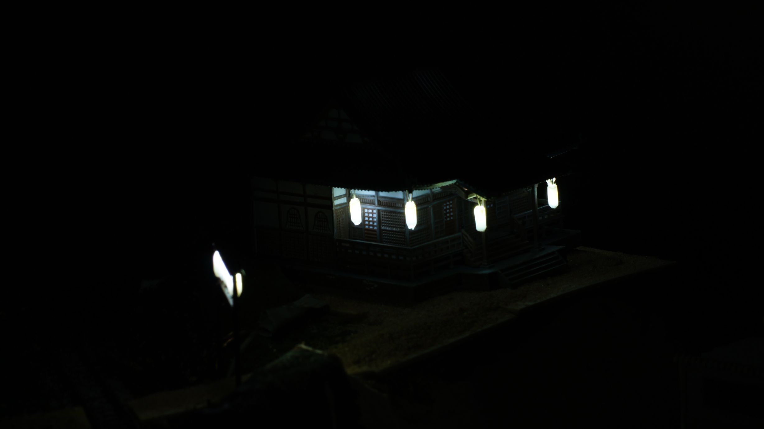
Lighting a Japanese Temple
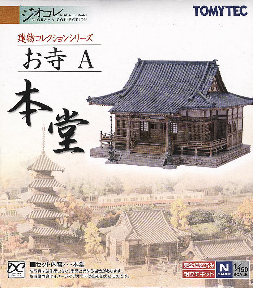
I'd decided it was time to light the temple after building the Torii for the entrance. This temple was the Tomytec Japanese Temple A (Main Building) and is still available for purchase from most Japanese online hobby retailers.
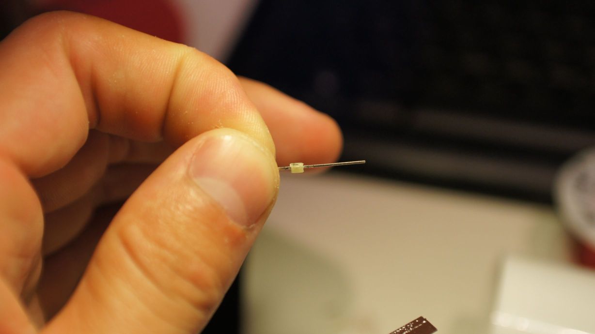
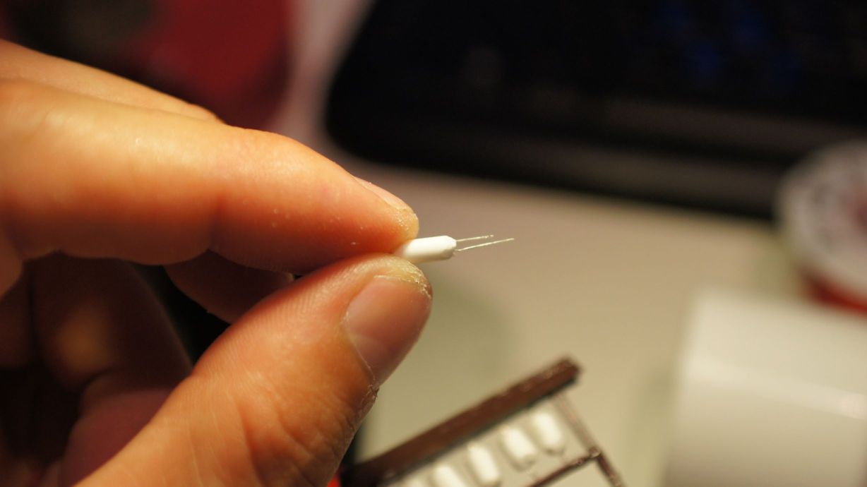
I've slapped LEDs in buildings before, but this time I also wanted to add lanterns to the front of the shop. I'd made the lanterns before, as in my previous attempts of creating the Torii, but I was to make a few changes this time as I wasn't totally impressed with the previous outcome.
Creating the lanterns
There was a slight change this time to creating the lanterns... instead of cutting them and sliding them over the LEDs, I shaved them down to fit and inserted them into the center of the tubing. This all worked well, but you must be careful when shaving down the LEDs as you can destroy them quite easily. To shave the LEDs, I held them in pliers in one hand and filed away with my pocket knife. It was pretty obvious to feel when you were no longer filing away at plastic and, unfortunately, this was usually the demise of the LED.
Mounting the lanterns
I used the same copper winding wire that I always do and bent it into a rectangular shape to fit the roof of the temple. I then started soldering the lanterns in place.
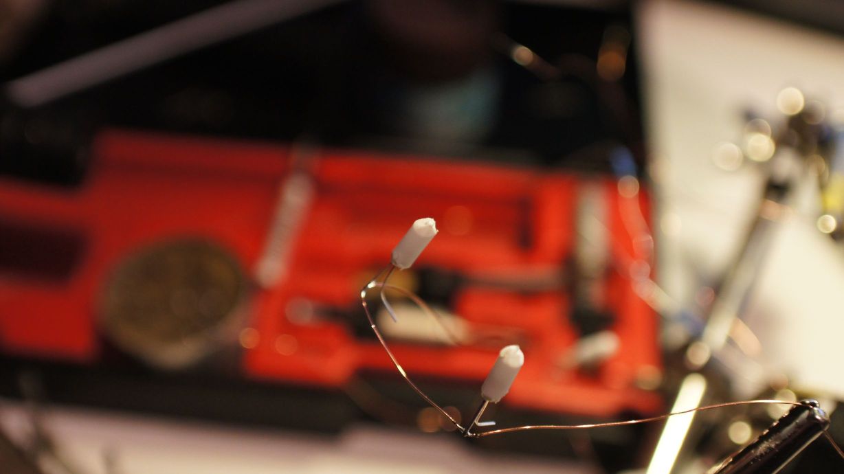
I then pulled out the trusty Selleys Aquadere and, using random aligator clips found on the bench, glued the lanterns in place.
I also put two standard 3mm white LEDs in the center of the ceiling for building lights.
The finished product
After the glue had dried, I tested all the LEDs and found that I'd broken the front-left lantern. This was 24hours after starting the project and frustrating. I quickly removed it from the temple and filed another LED down. I left it dry again, overnight, after testing, gluing and testing again.
Finally, yesterday, I was able to hook it up to my Arduino LED Controller. It worked perfectly and I took the opportunity to test my night-time photography skills.
Now to settle the landscape around it.
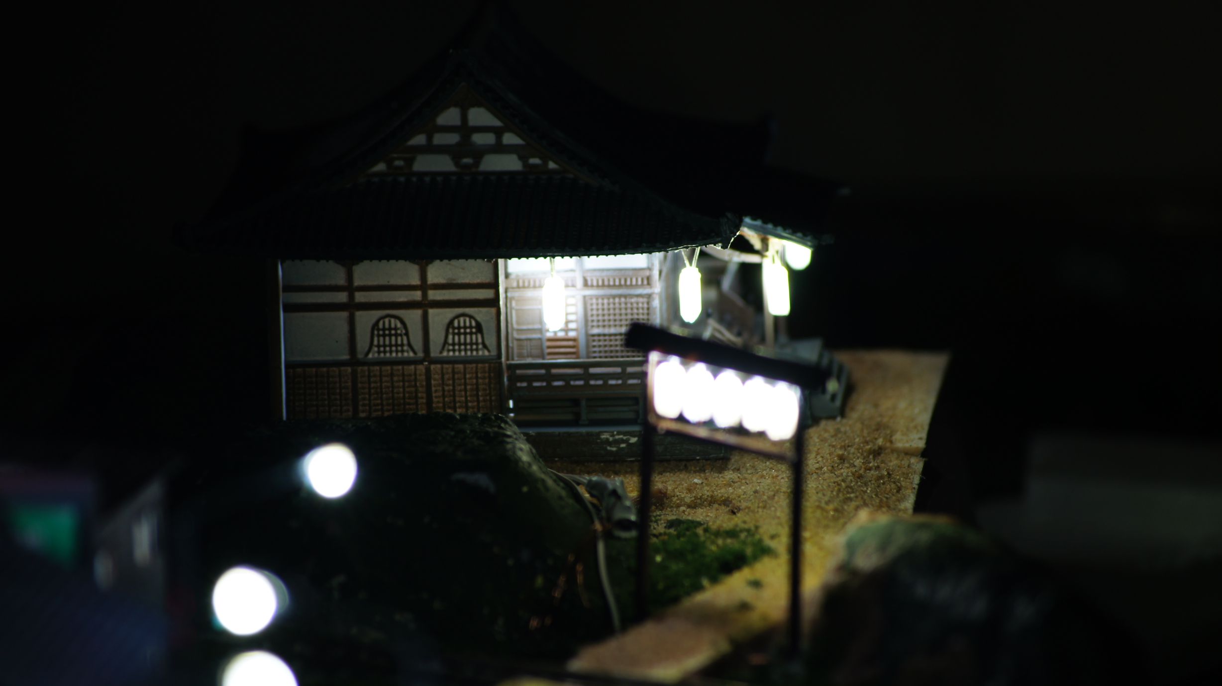
Creating a Shrine Torii Entrance
After checking out more of the work by tanaka_ace on the Tounosawa Blog, I've decided to add a Japanese Shrine to my layout. I've extended the upper level to allow room for a kit I bought in Japan last September and have created a path back to the main town area.
As with any Shrine in Japan, the grounds are seen as sacred and insulated from the surrounding area; usually by either high walls or thick vegetation with a Torii gate for the entrance. I'll be adding the walls in soon enough, but prior to doing so I wanted to make sure I had all of the buildings and scenery effects in place.
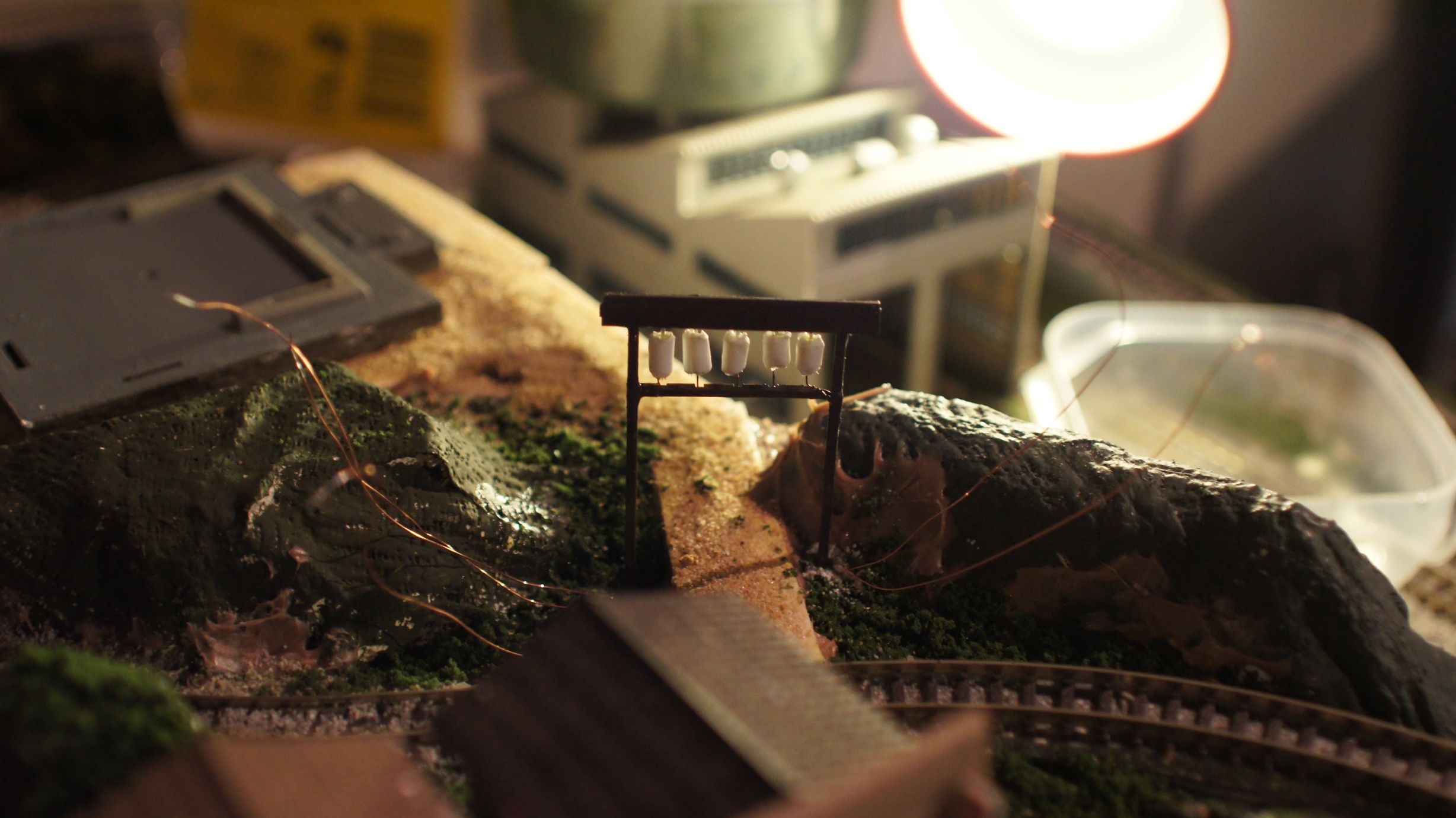
The first thing to create was the Torii gate entrance. Tanaka_ace on his Tounosawa Blog had created a very nice gate with LED lanterns added. This is all based off a real-life location at the Tounosawa Station on the Hakone Tozan Railway. He had also created a blog post showing what he based the model off.
My version
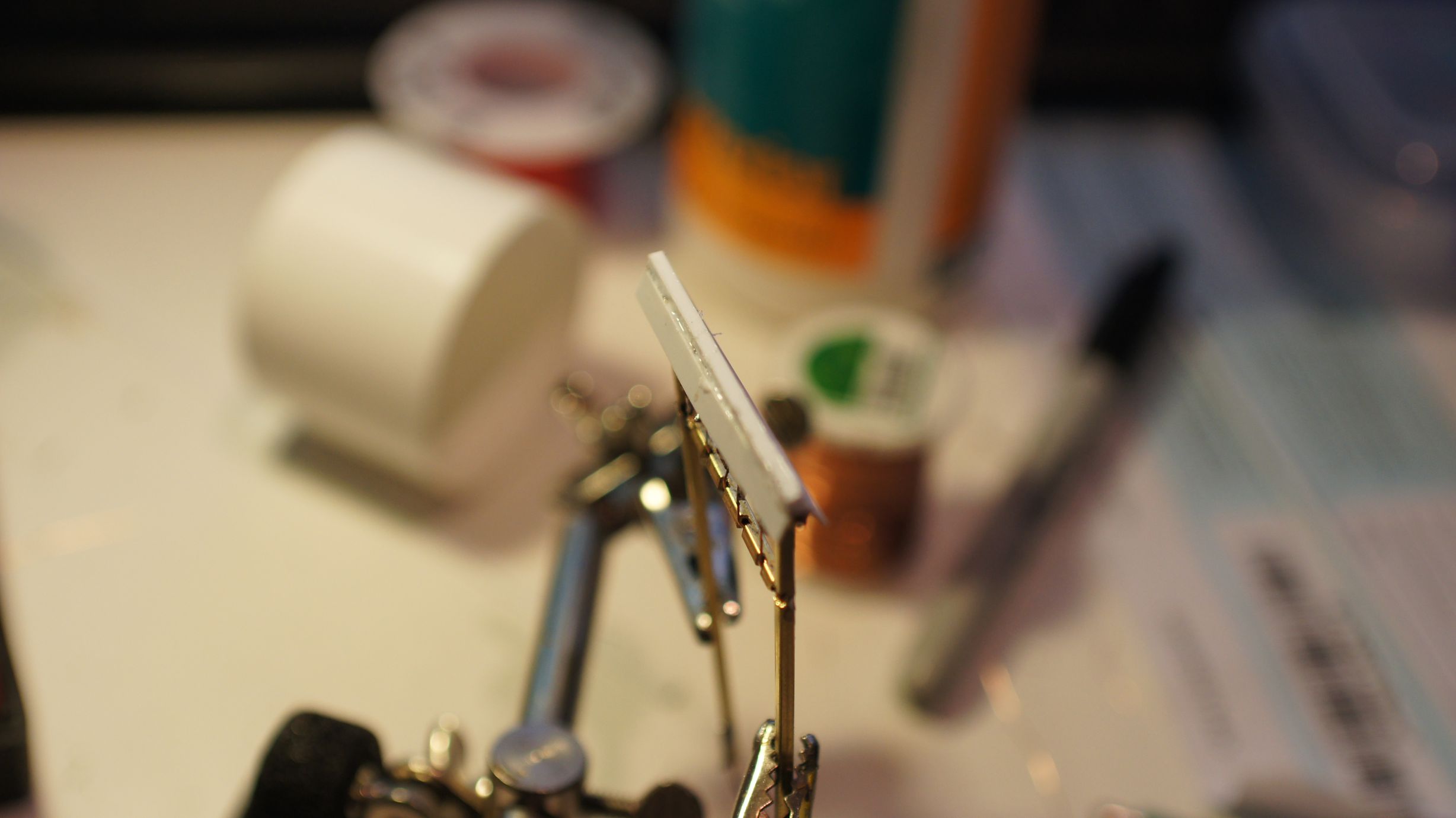
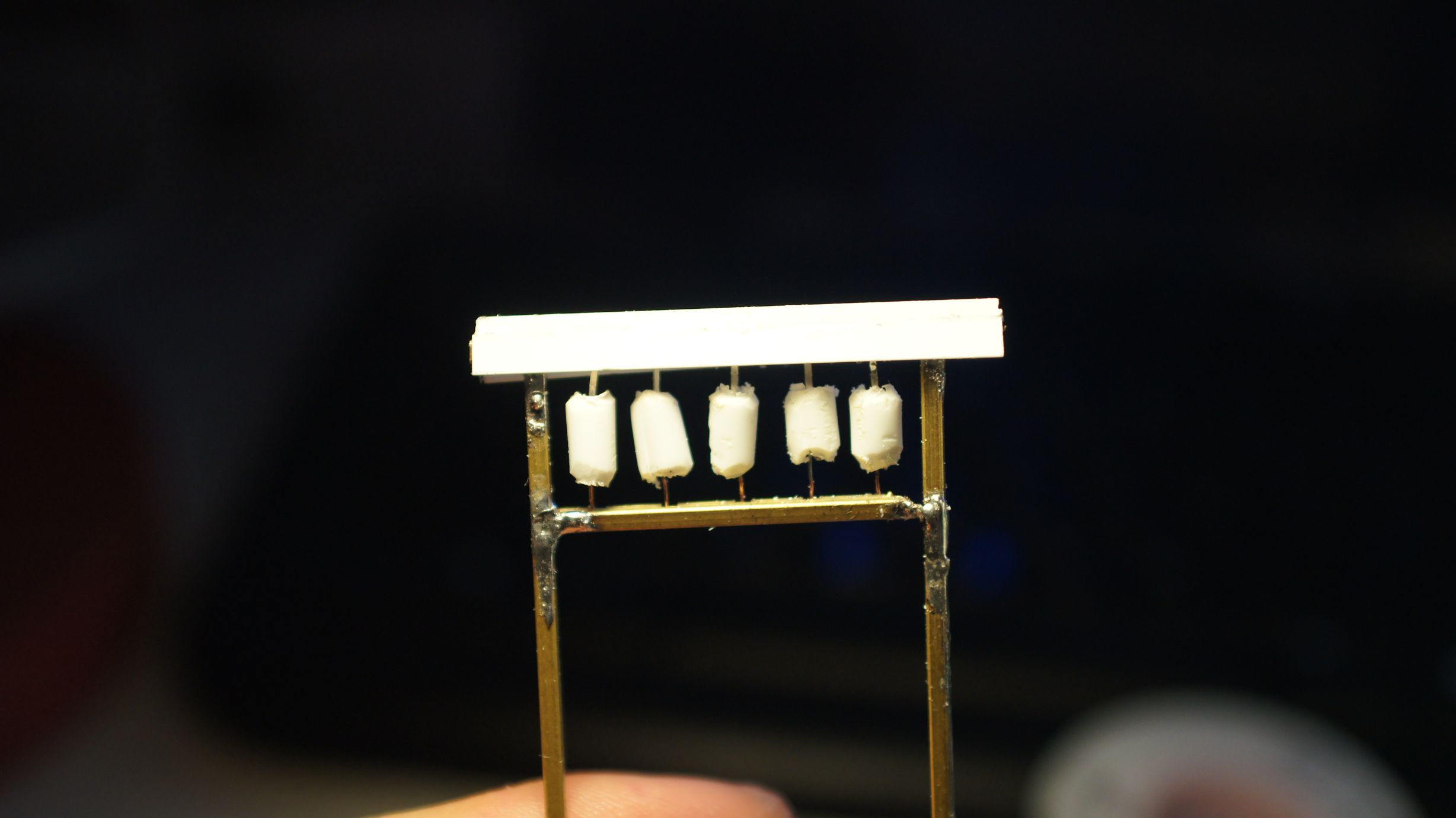
I've used the same gauge winding wire I'd used for my level crossing lights, streetlights and building lighting. With this I've also used 1/16" brass pole for the main frame of the gate because I wanted to emulate wood rather than a cylindrical concrete post this time. This also provided a little more room to squeeze the wires through. Each length needed to be cut down to size and then filed back. I used standard snips to cut the brass, a smaller saw would've been a better idea.

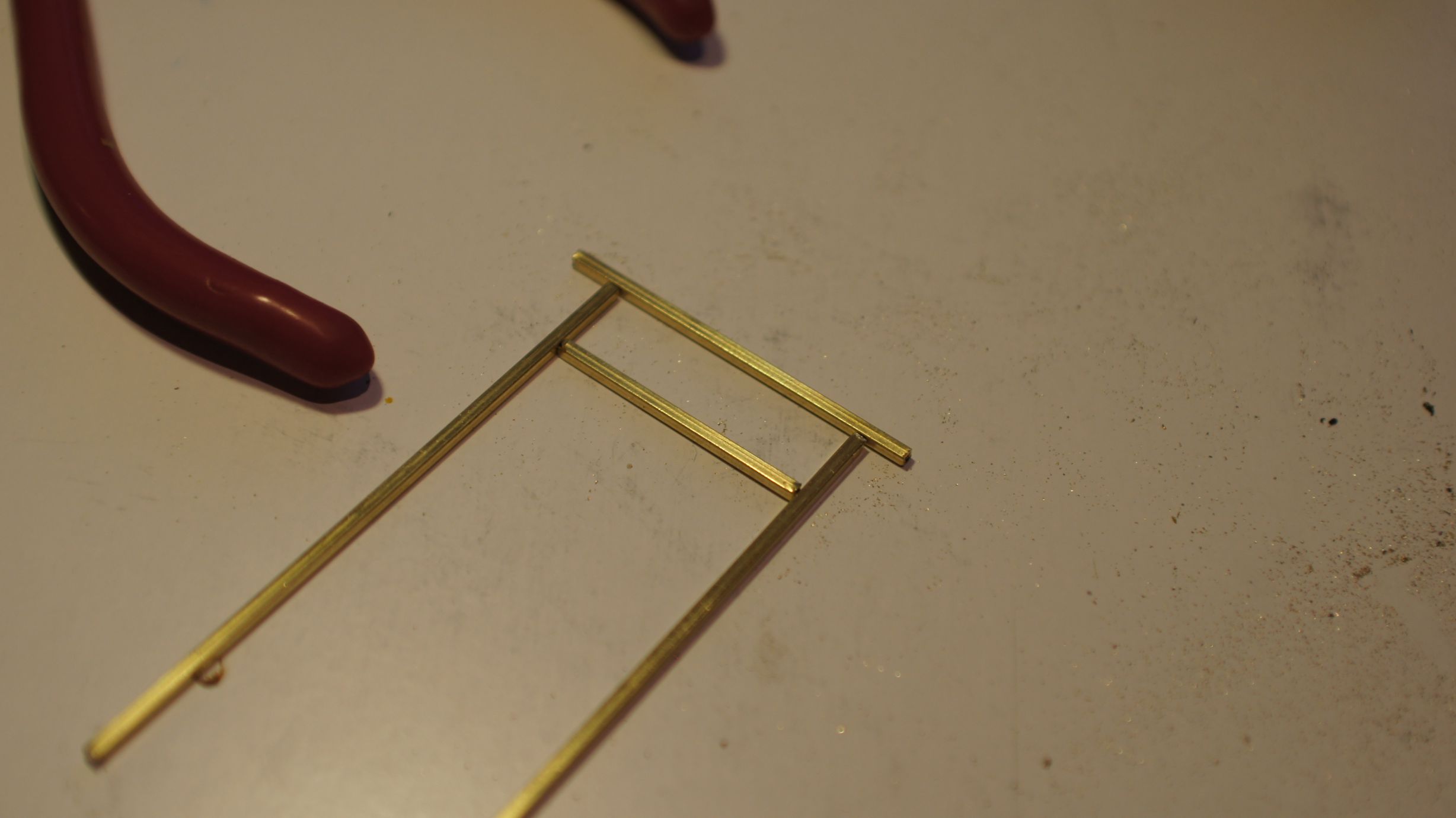
I based the size on the path that I had already created on the layout. I didn't really have a real-life prototype to work off and made a lot of it up as I went. The final size was around 50mm wide and I could fit 5 lanterns in. Below you can see the framing taking place.
I then started cutting out the holes to feed the wire through. I used my trusty pocket-knife as the brass was quite soft. I also used a wire cut off a resistor to clean out the tubes of any metal shavings. The entrances created for the wires would have sharp edges and could scrape off the insulation on the wires, so I made the holes as big as possible.
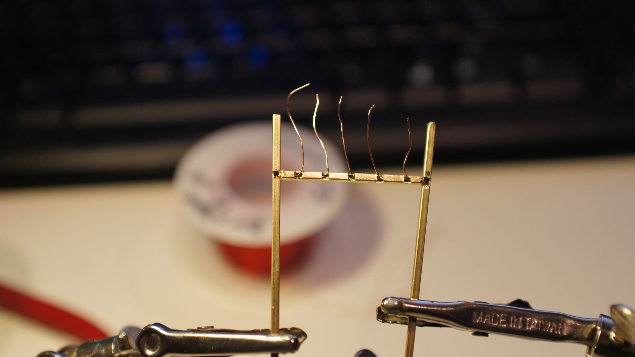
Once the holes were cut, I fed the wires through as a test. I then constructed the frame with solder. At this point I accidently overheated the wires on the left side. This caused one to ground and I then couldn't successfully light 1 of the 5 LEDs. I took more care the second time around when soldering the frame back together.
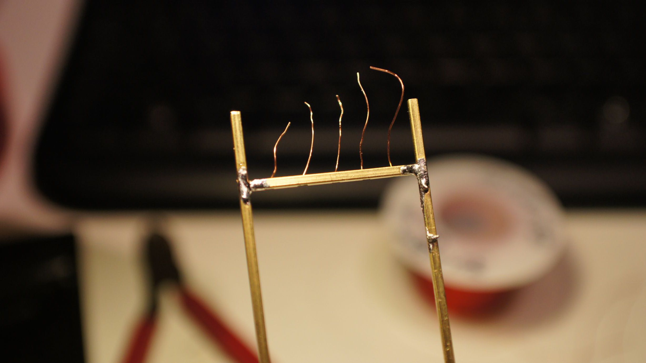
I added a quick roof to the frame as tanaka_ace had done with his second version.
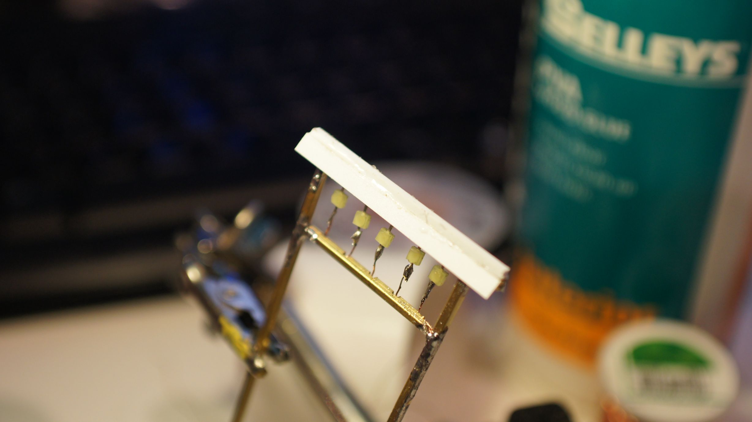
Now that the frame and LEDs were in place, I could go about turning them into lanterns. This would be done by putting plastic piping around them. I had already done this with a fixed lantern on a TomyTec Japanese Shop, but this time I had no existing lanterns to work with. I therefore used the same concept as tanaka_ace.
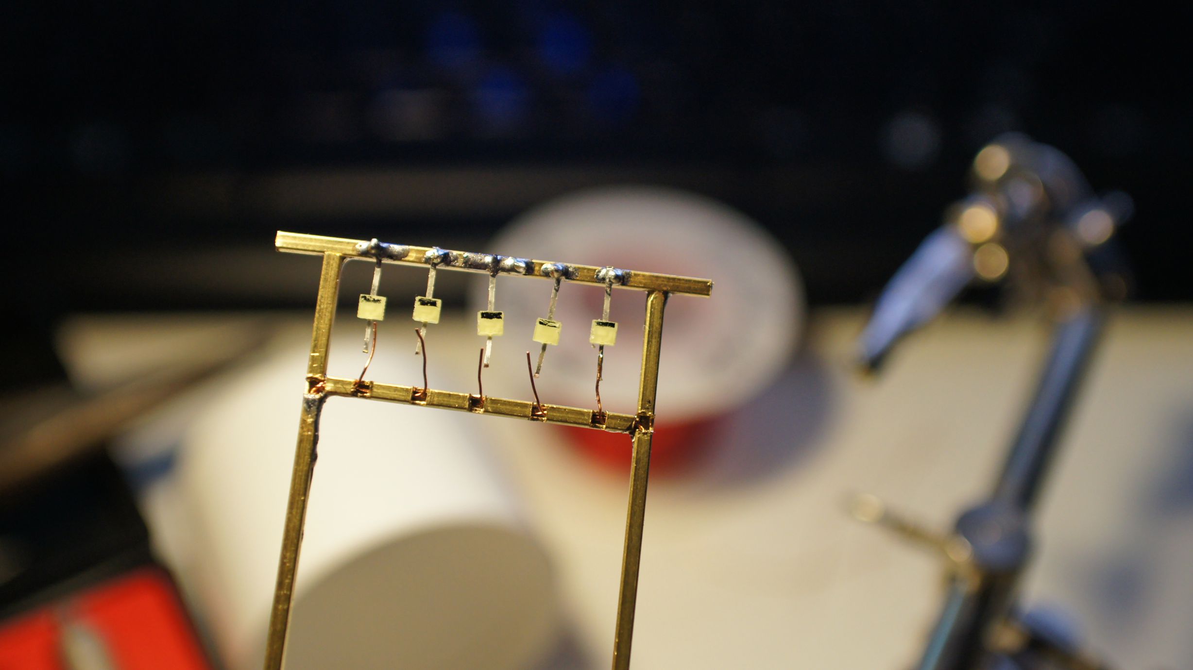
Thanks to globalisation, I was able to acquire the exact same "Evergreen Scale Models" poly-piping that he used. I happened to purchase 3.2mm pipe instead of the 2.4mm; but this worked out well as the LEDs that I was using were a little bigger. The pipe was cut into appropriate lengths and then the edges rounded down to create the lantern shape. The individual lanterns were then sliced at the back so that I could slide them over the LEDs. I then used stock-standard Shelleys Aquadhere to fill in the ends.
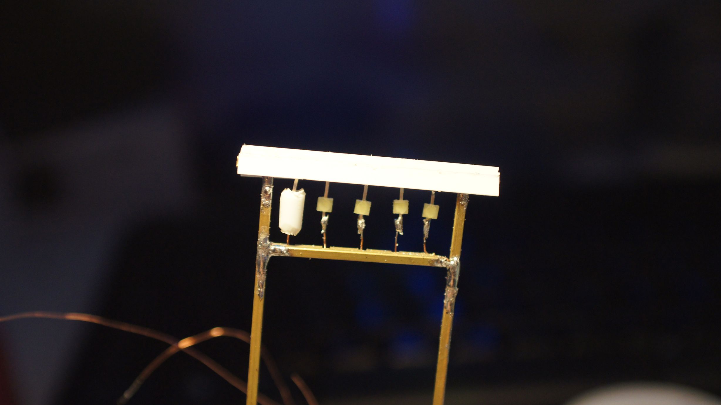
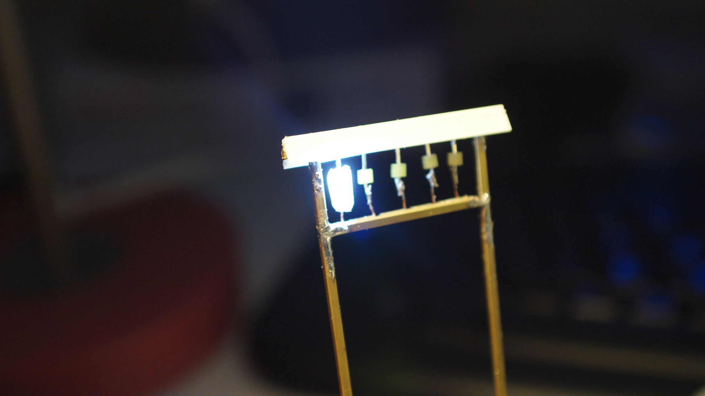
Once these were holding in place, I painted the frame a nice wood-brown. Torii gates can be made of wood or stone and painted a multitude of colours. You more often than not will see them in brown wood, but bright red, and even out in the ocean, is not uncommon.
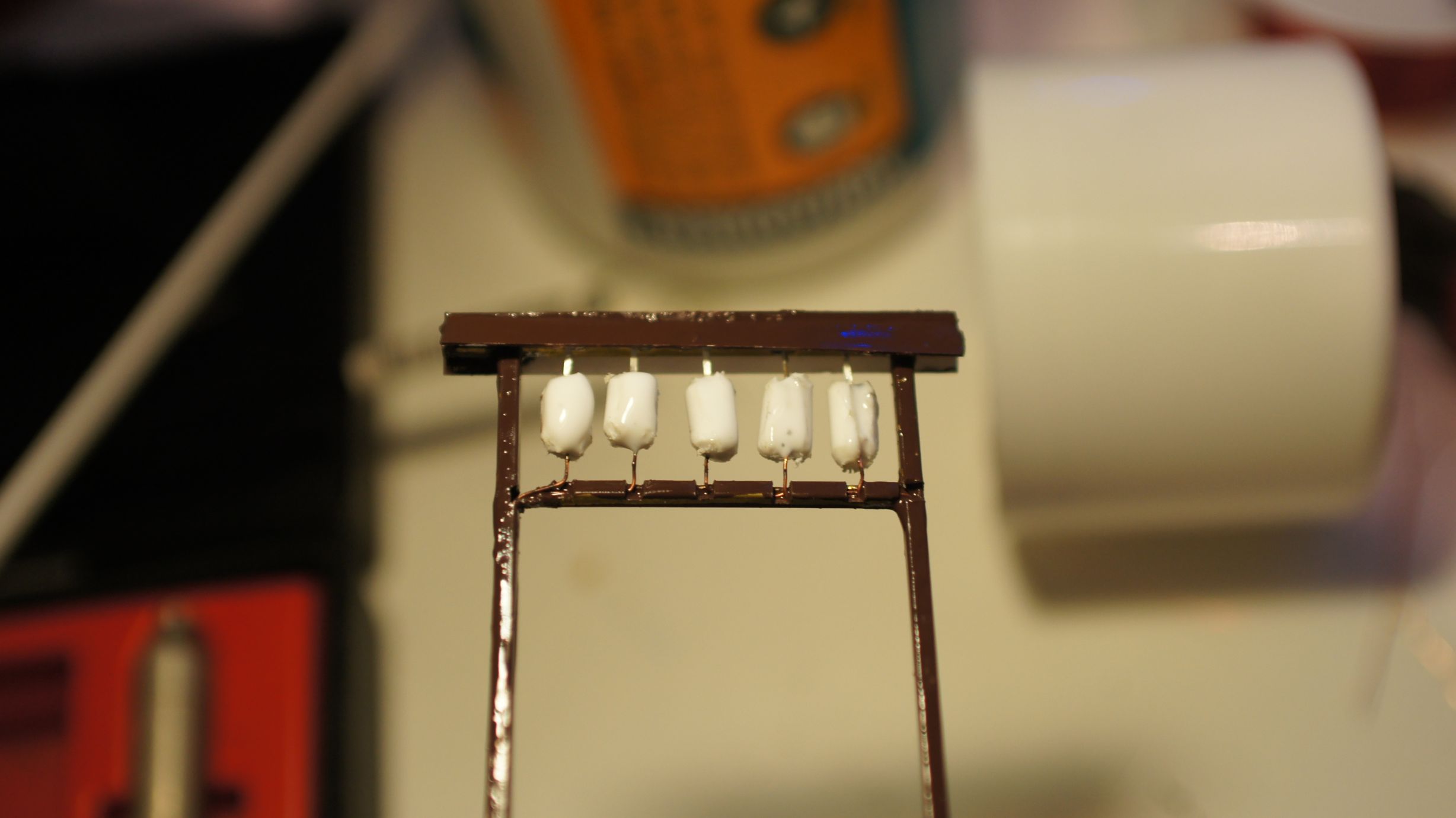
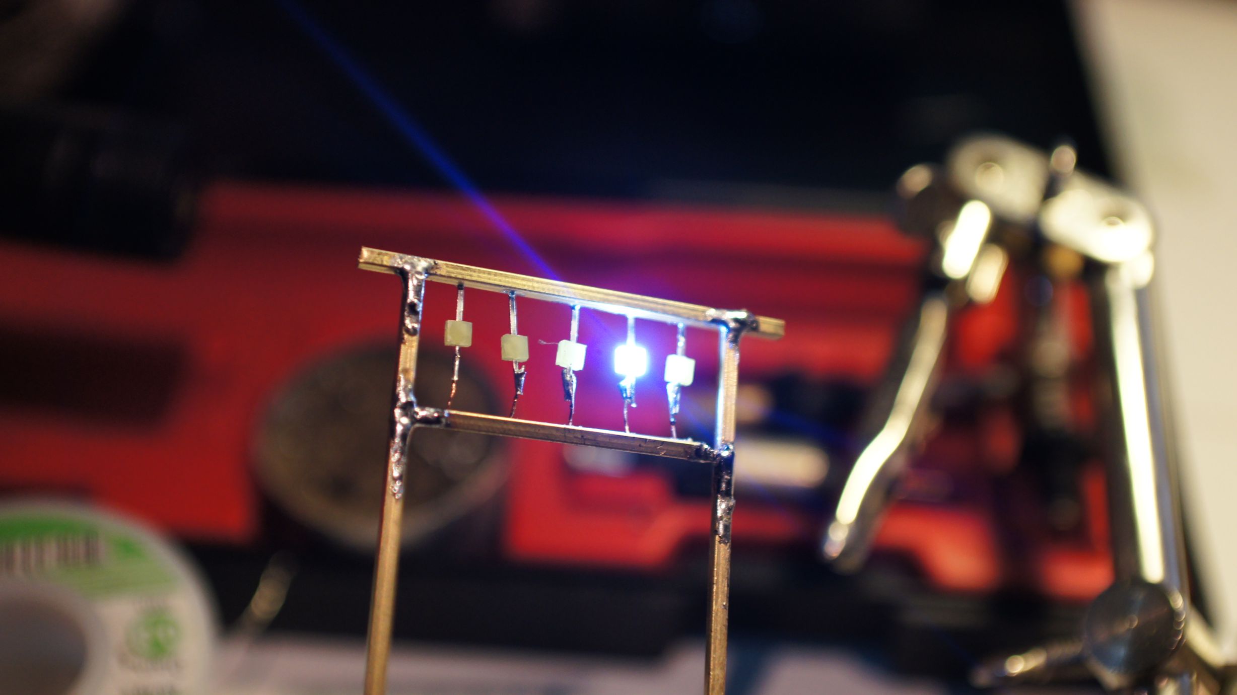
And that was it... I still think I need to place some characters on the lanterns, but I need to work out what to write on them. I also should've taken more care to get the lanterns even, but I was happy enough with the outcome and, once in place on the layout, knew it would be good enough.
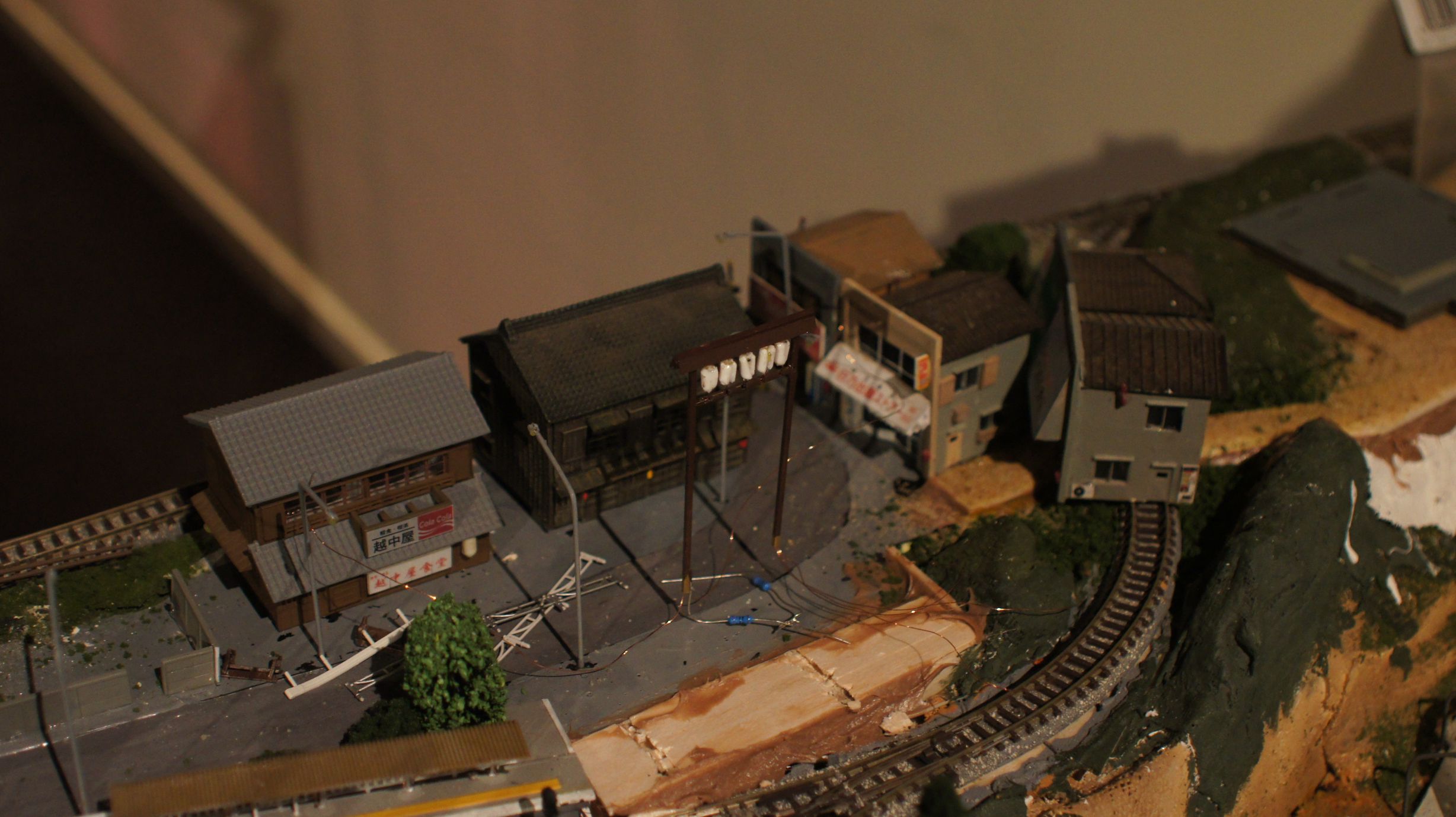
Now that the entrance is in place, it's time to get the fences and shrine in. As you can see, the foundations are there already and I'm currently working on adding lanterns and lights to the shrine.
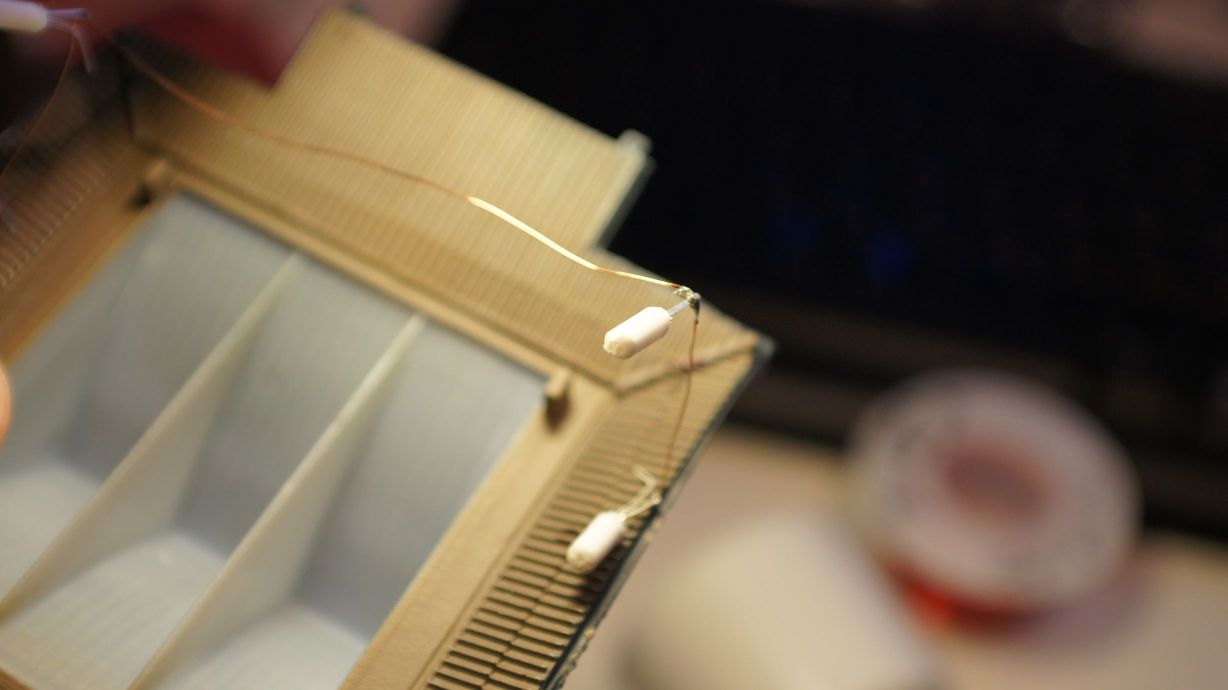
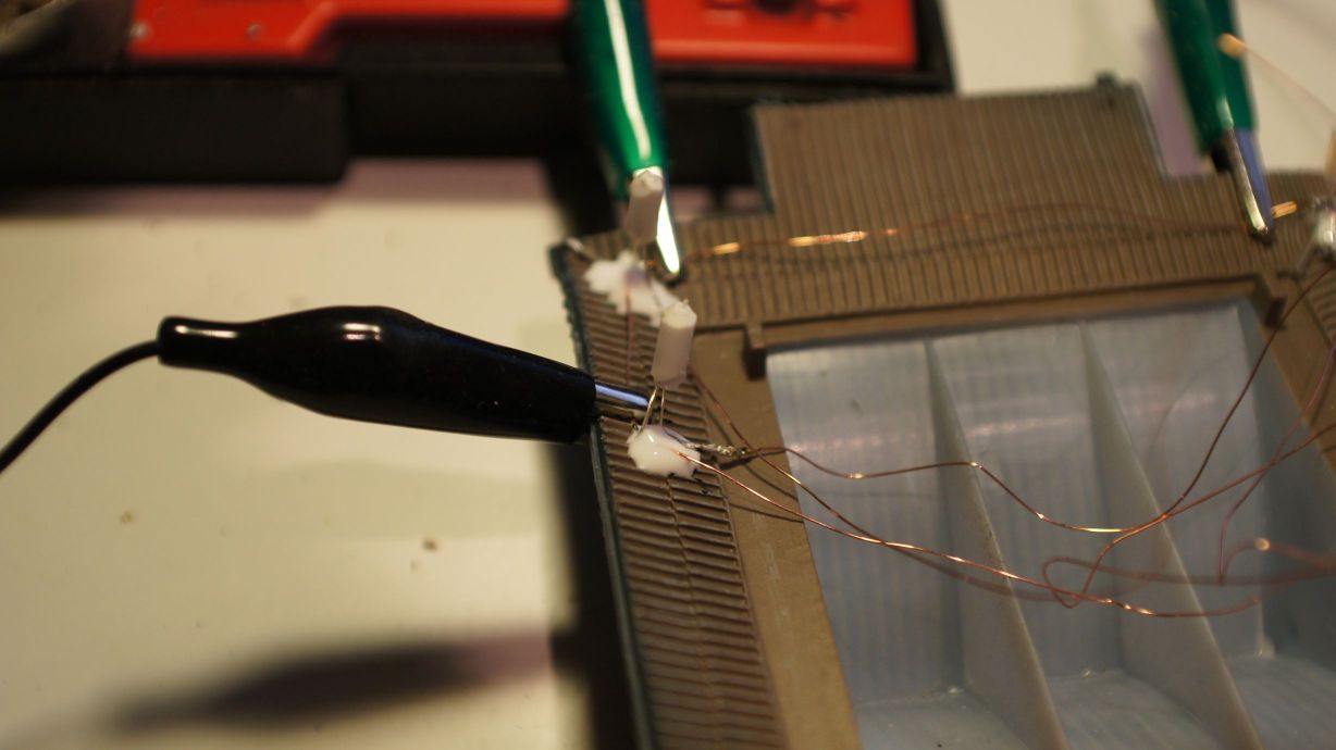
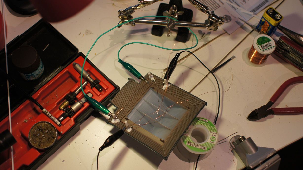
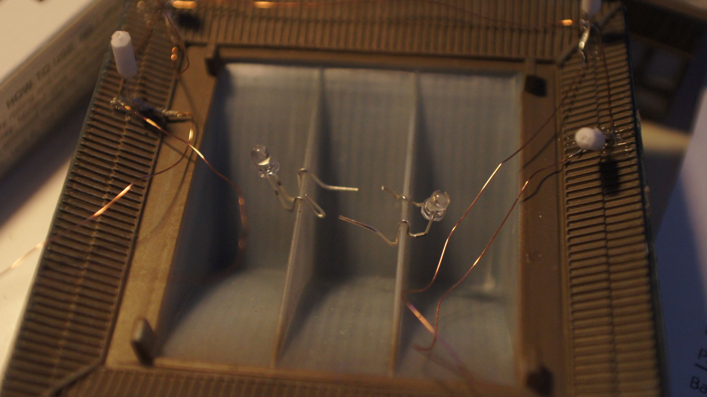
Adding LEDs to a Japanese Shop
Pictures speak louder than words, so below is a quick tutorial on how to get an off-the-shelf TomyTec Japanese Shop Building lit with LED lighting. In total, this building received 6 LEDs; lantern, side-door, top floor (x2), bottom floor (x2).
Interior Lighting + Side Door


The trickiest part of this installation was the lantern that hangs out the front. I actually sliced it in half and bored out the middle to fit an LED inside. I also trimmed down the LED with a file to get it to fit a little more easily. This was done with my pocket-knife and I stopped when I felt it grinding metal. :)
Note that I borrowed ideas from this blog and I strongly recommend you check out the work the author has done on their layout!
Front Lantern


And finally, everything is wired up. You can see the huge hole I accidently drilled in the side of the shop... luckily the lantern covers it over pretty well.
Finished Product


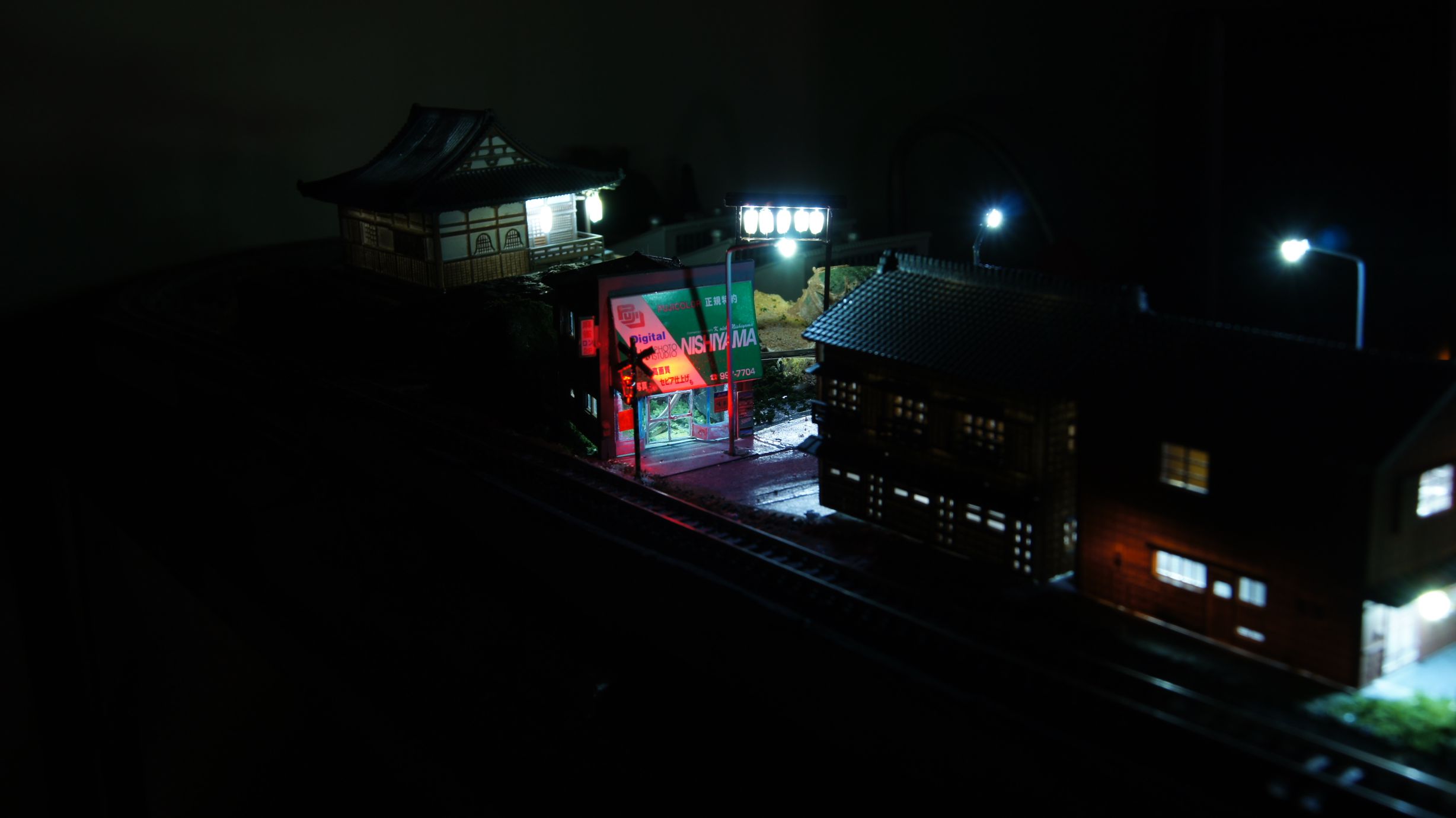
Cheap and easy Streetlights
I'd previously bulk purchased a large amount of LEDs from LED-Switch with the intent to light up my entire model railway. I'd already bought a few of the MAX7219 ICs, which control up to 64 LEDs each, and knew how to control these via the Arduino. My article on the IC and using it was here.
Anyway, streetlights were high on the agenda, as they exist in every town in Japan and, based on a very simple idea, weren't going to be too hard to make. Following are the steps involved with creating the street lights that have been visible in my prior articles.
Ingredients
- 0.25mm Copper winding wire (or as thin as possible.)
- 1.6mm LEDs White/Yellow (as available here)
- Metal tubing for the main pole. (I used '3/64 x .006' brass tubing)
- Soldering iron
- Paint


Construction
Firstly, cut the pole to your desired length. I have to admit here that I never once measured any of the poles and just prototyped one against a reference (in this case it was a standard Greenmax building) and then made them all the same size.


Make sure you take in to account where you will bend the pole and how much extra length will be required. Use a file to smoothen out the ends so that you don't damage the winding wire when fed through.


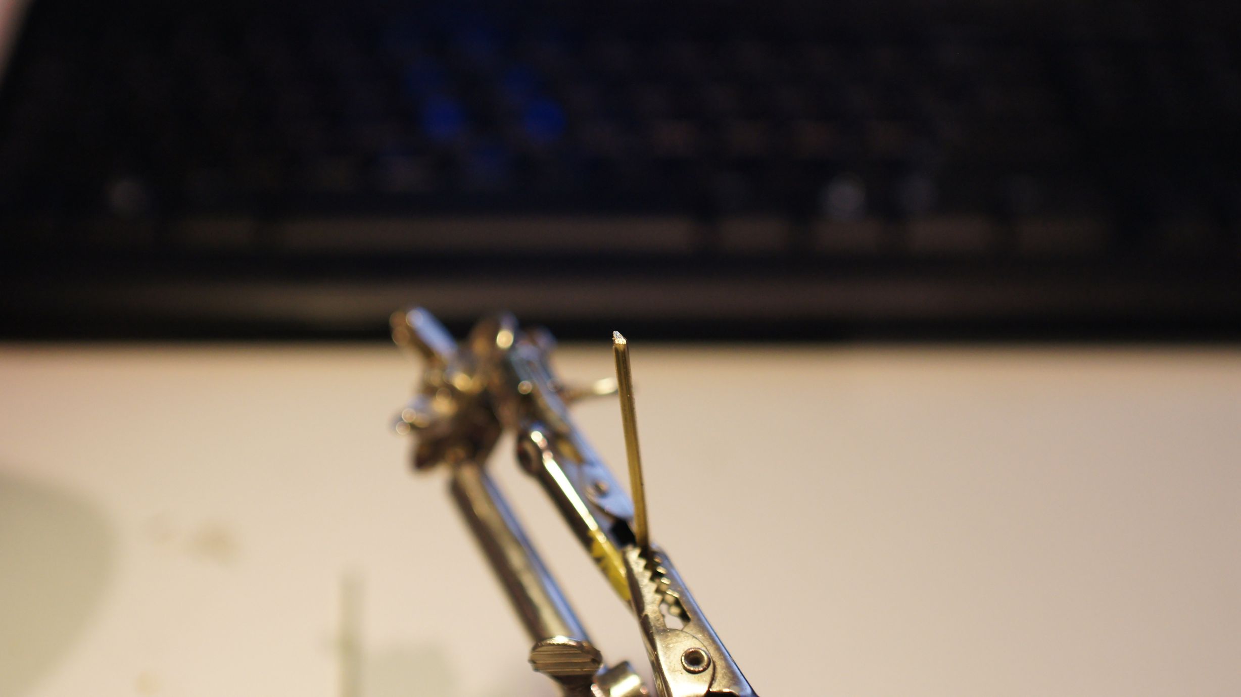
Once you have the poles made, simply cut the leads of the LED right down and solder one end to the pole itself. Finally, if you haven't already, feed the wire through the pole and tin one end (melt it with a little bit of solder to strip away the insulation.) Once done, trim away any excess tinned lead and then solder it to the other lead of the LED.


Note that the final version there was the best I'd made. I'd trimmed the LEDs right down after folding one leg over the top and used a very small amount of solder.
Finished Product
Better night shots of the taller version in action...
The only thing these really require now is some form of cover/compartment/housing for the bulb to live in. Currently, with a big enough blob of paint, I can get the ends to look round-ish enough to look acceptable and I'm happy with this. But any comments/suggestions for an off-the-shelf product that might have the right shape to cover the ends are welcome!
I'd also bought red, yellow and green LEDs and found that they had fit into the Greenmax Signals. I haven't gotten around to finishing them, but I will post another article once done.
Meanwhile, in my previous post, I also added both a red and blue LED to a Bachmann N-Scale Signal. I actually cut it off its usual pole/base and mounted them as shunting signals. See the pictures. I'll post a more detailed explanation along with the other signals once finished.
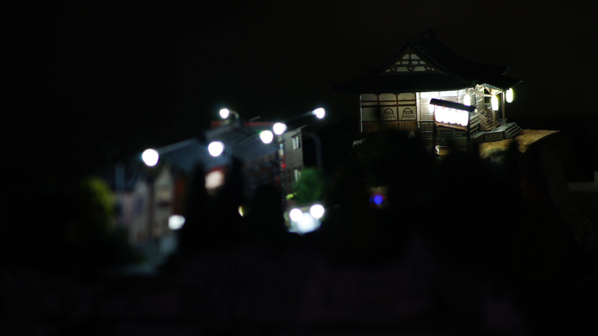
Latest on the Model Railway
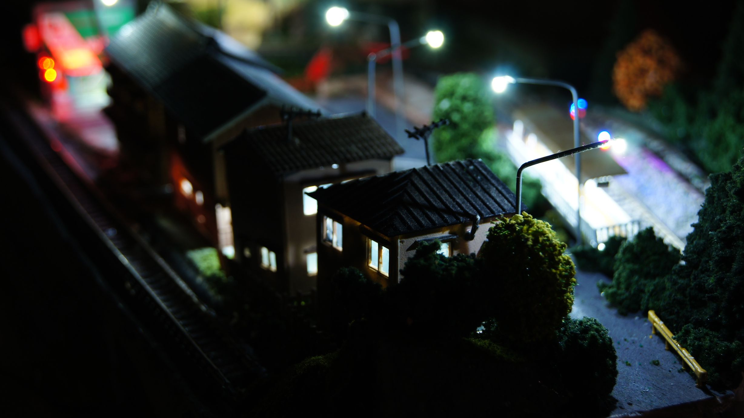
So, something that was just meant to turn into a test layout has now become one of my greatest creations... It's not much as yet, but the scenery and electronics involved is a lot more complex than I thought I would ever create and I'm really glad as to how it's coming along.
Here's a gallery of the initial track plan I intended on using and then 3 evolutions of it. The final layout is not actually listed there. You can see that it started as a single level basic loop, with options for expansion. As I realised the time required for building just this module, I decided to do away with the extension options (although things can always change) and then added a second level. This was just to be a ridge down the middle of the board, but it now has transformed into 1/4 of the overall surface area. A town has now grown on top and a nice siding for single-car vehicles.
Underneath the board is a birds-nest of wiring for all the tricks I've tried with the Arduino (see all the previous posts...) and I'll show you this in a later post.
For now, just check out the photos and I'll get back with more information as I create it. I'm currently working on street lights for the top town and also automation of the points. I've been through around 5 iterations for the control circuit for the points and damaged quite a few TomyTec FineTrack Points in the process. Not fun.
Here's a link to the whole album.
Update: The streetlights are painted and in... I still need to work on the light end, they need some sort of cover/compartment.
Meanwhile, I also need to learn nighttime photography :)
More to come as I light up all of the houses; although one is already lit!
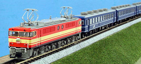
Kato Amtrak 13002 (Seibu E851?)
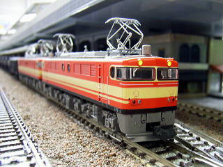
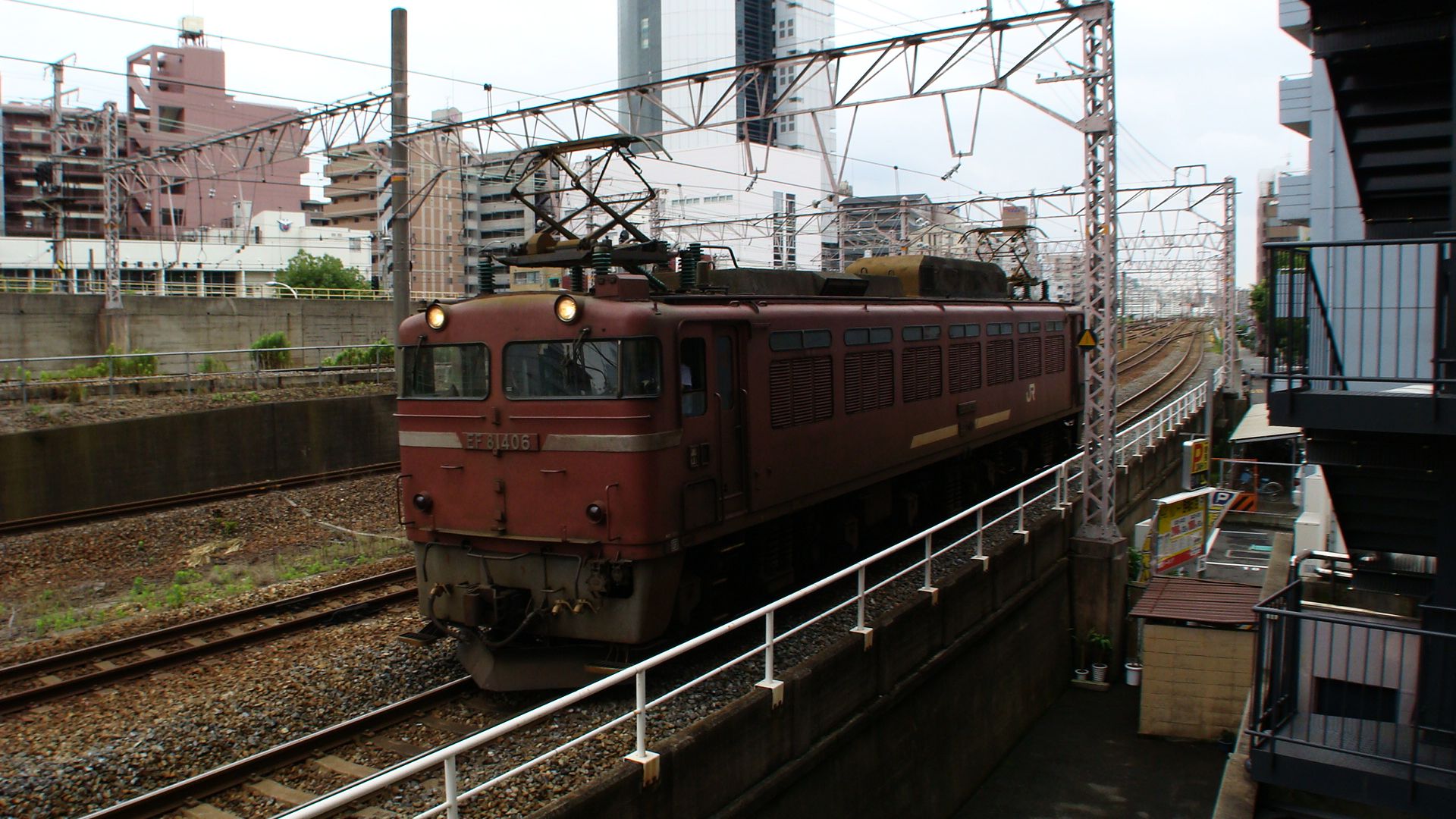
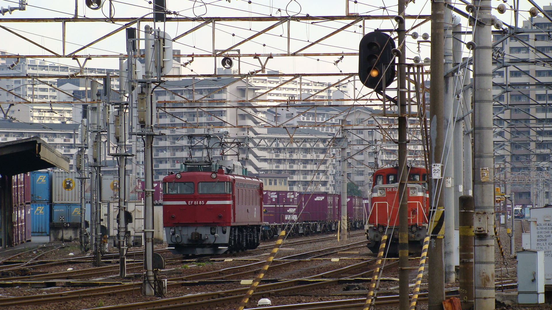
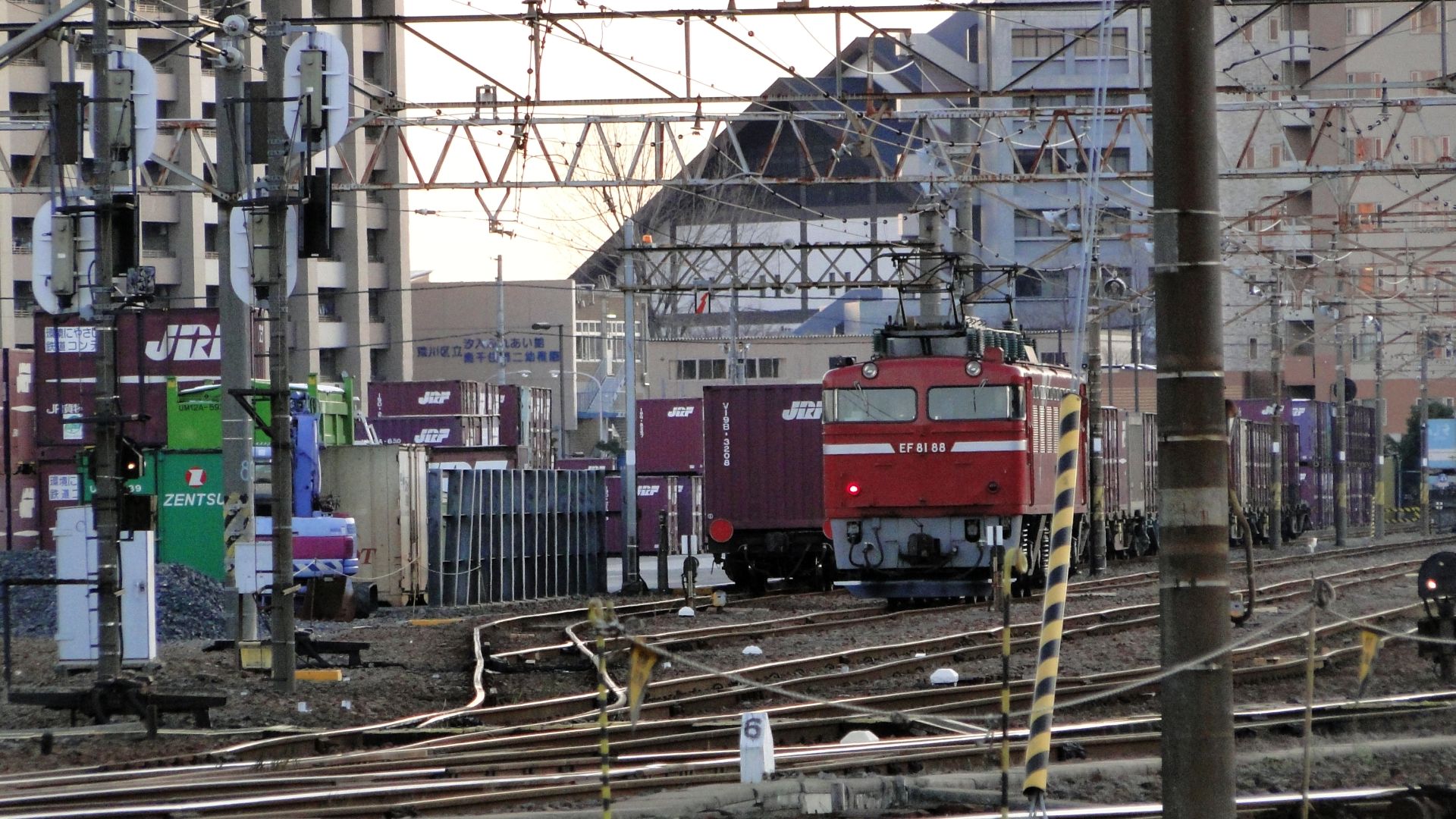
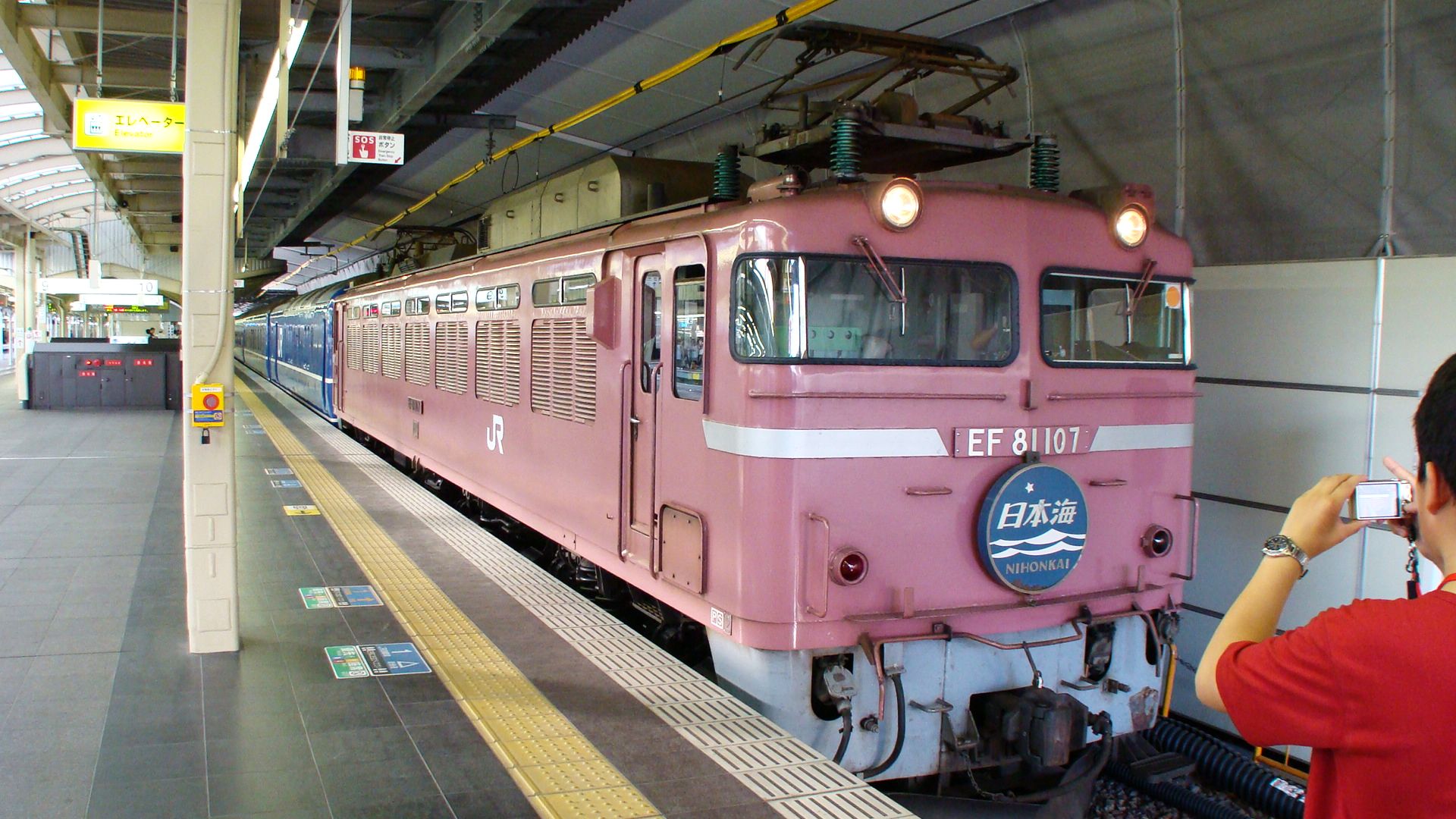
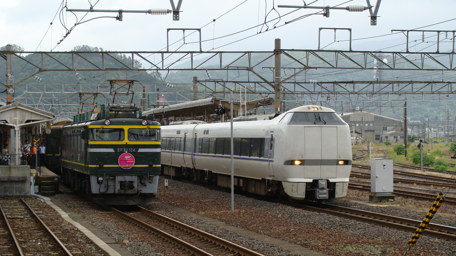
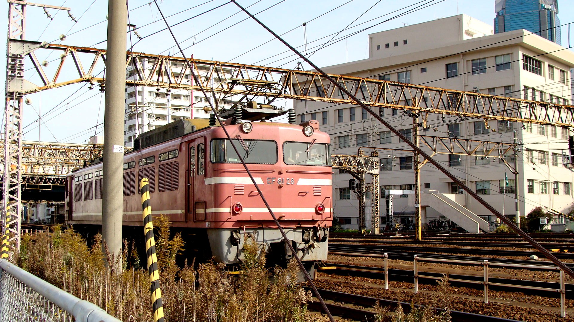
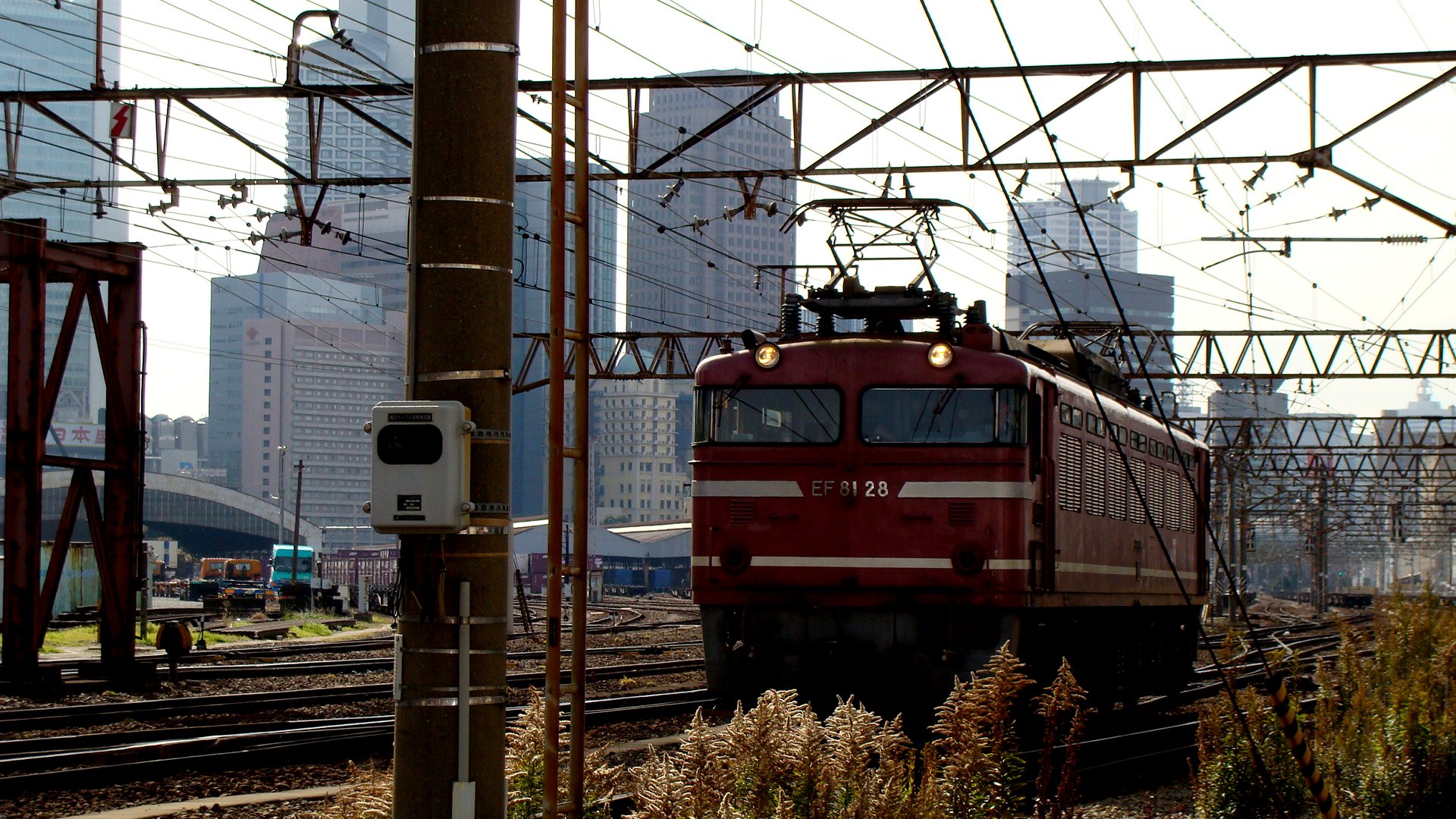
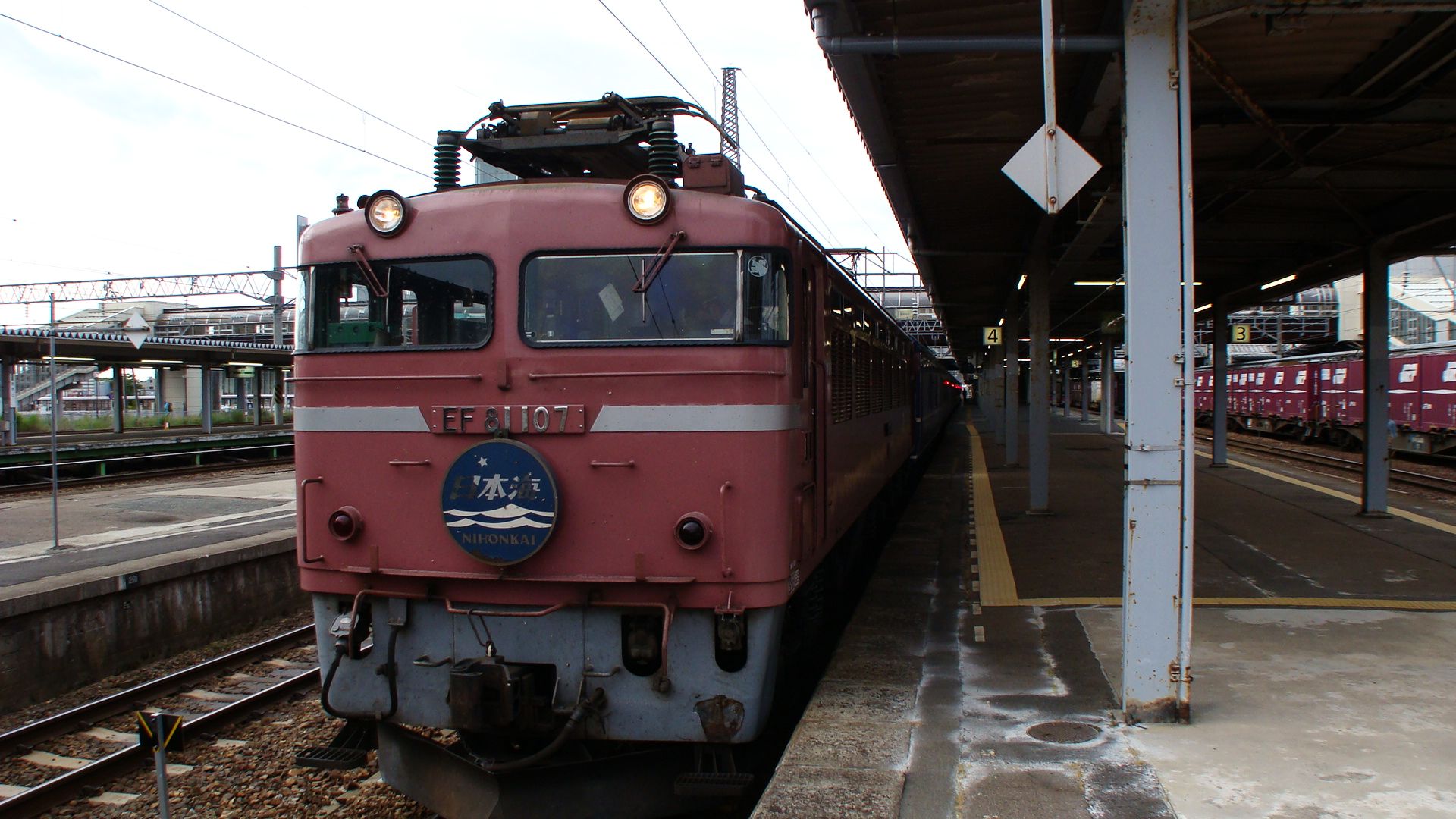
So, I was browsing eBay and saw advertised a Kato Amtrak 4+4+4 Electric Locomotive... For all I'd known Amtrak America had never had any such an engine and therefore clicked the item to investigate... In front of me appeared (what looked like) an EF81 in Amtrak livery!
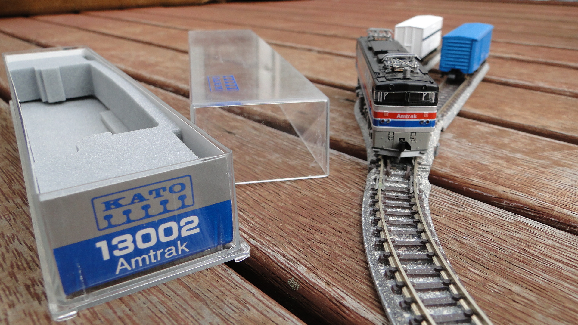
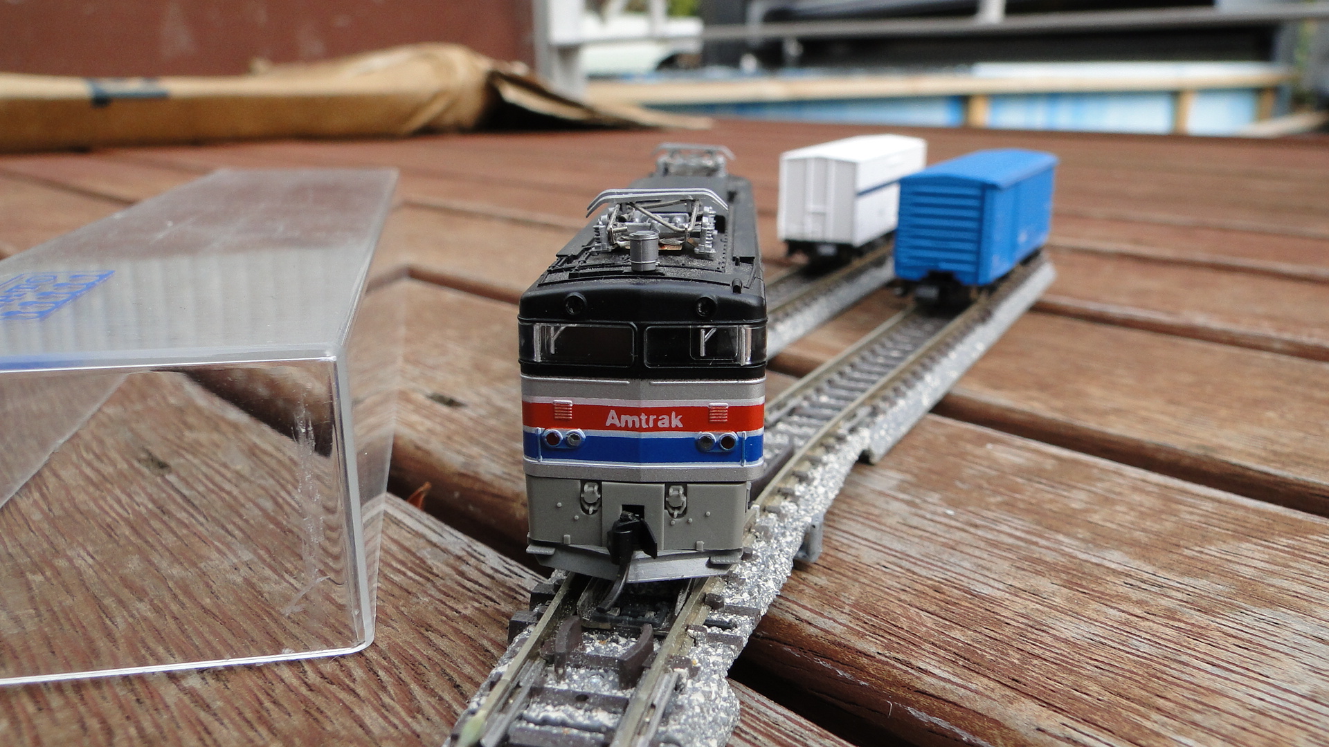
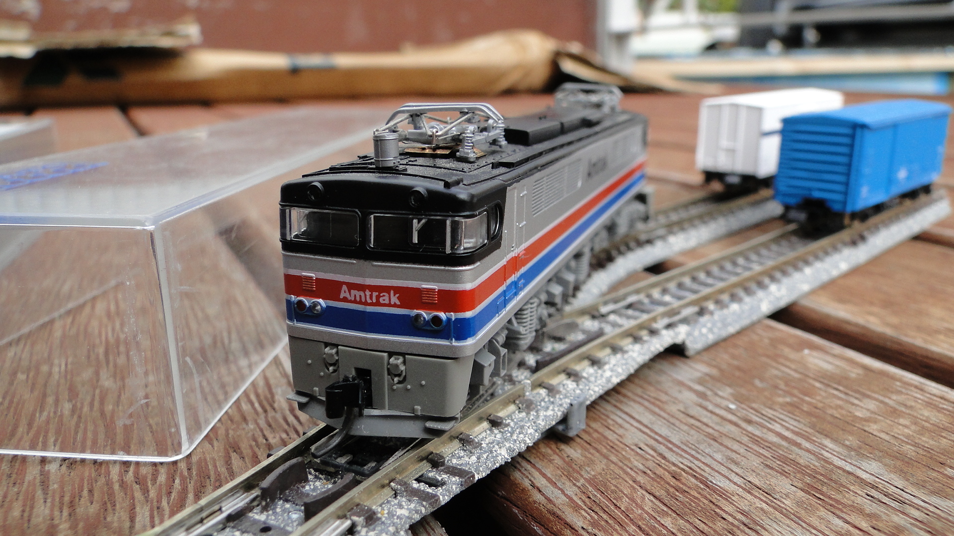
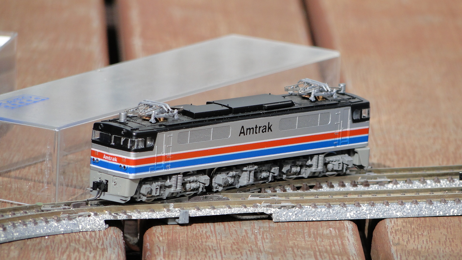
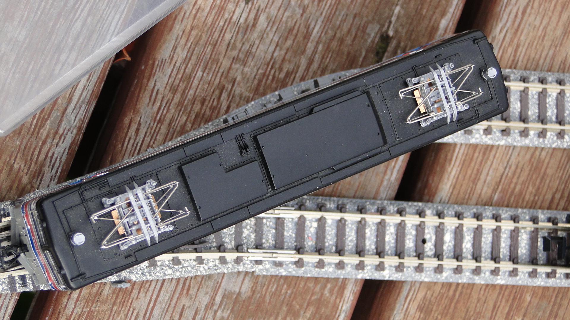
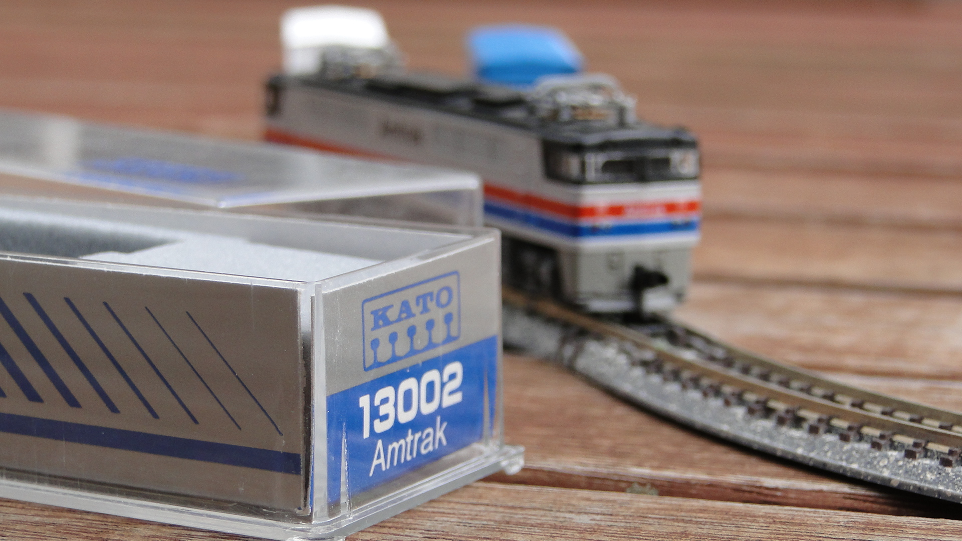
It seems that, back in the day, Kato didn't want to put money in to actually designing the models for America and therefore just repainted a (very slightly) remodeled EF81. Of course, it could be an exact copy of another Japanese electric locomotive, but I haven't had the time yet to do further research.
Update:
Toni Babelony of the JNS Forum posted a message in the thread I created on this locomotive that indicated that this is much closer to a Seibu E851. Thanks for pointing this out! Here is the Kato page on the Seibu E851. You'll notice that the Seibu has port holes, and other differences, but is obviously what Kato used as a base for this Amtrak locomotive.
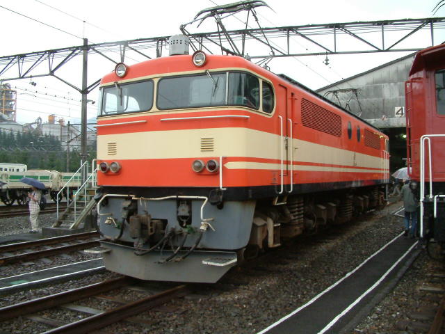
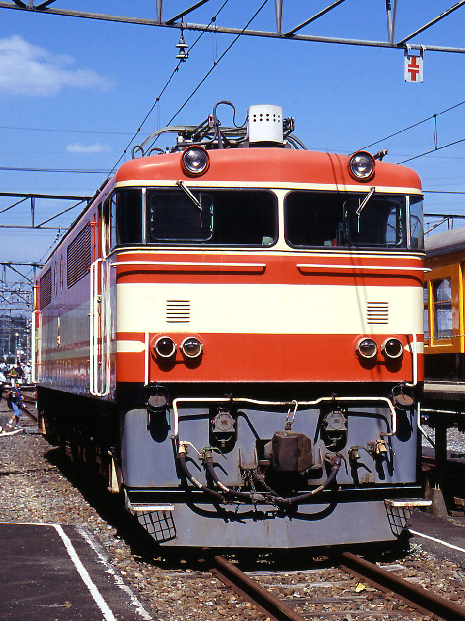
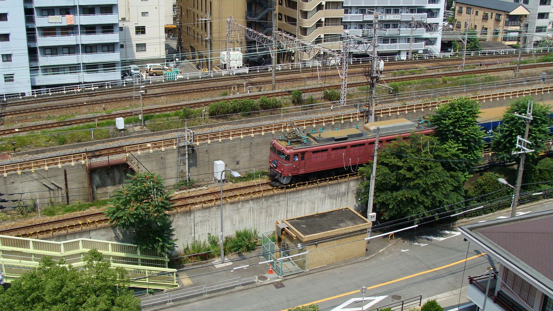
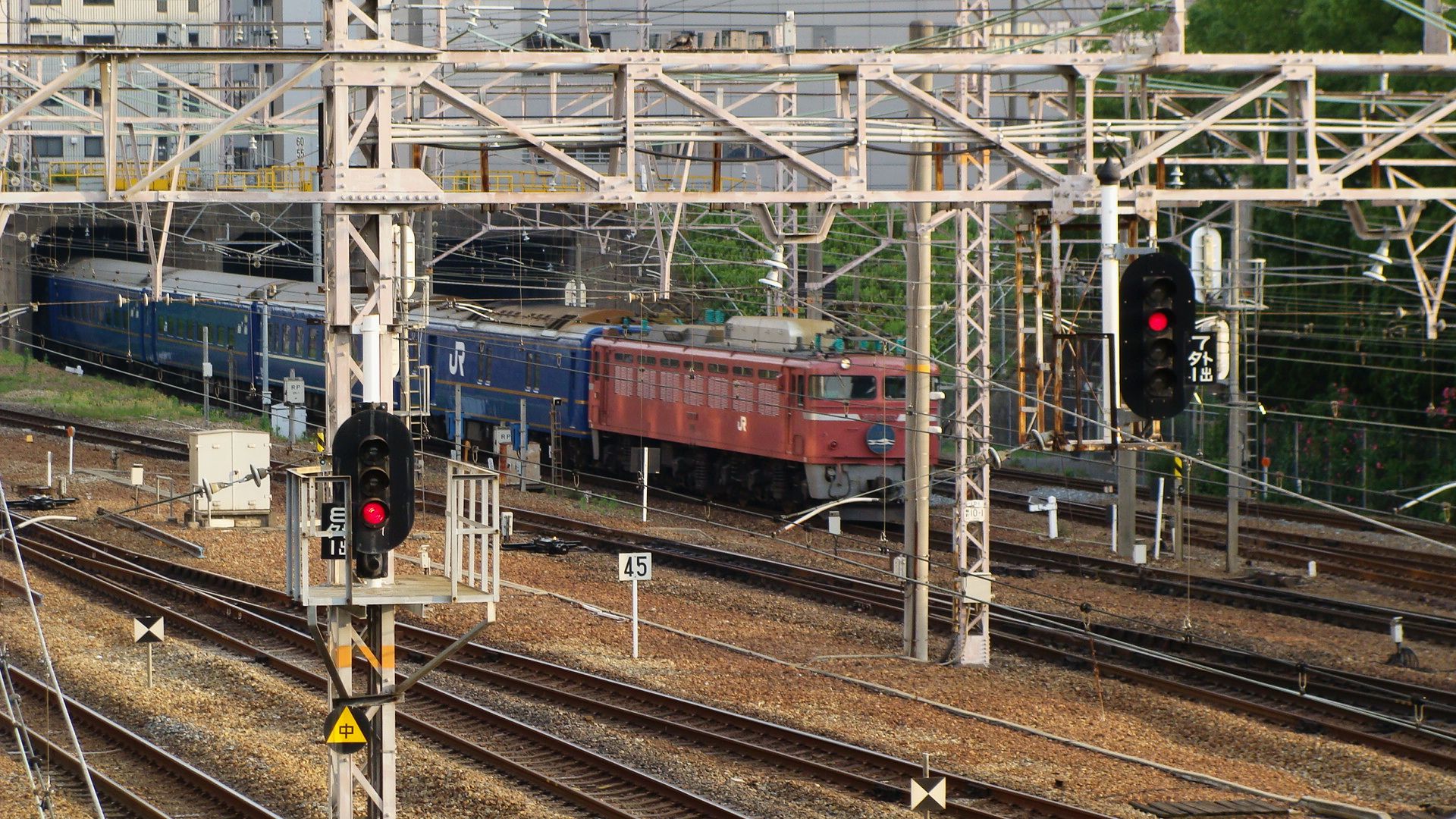
Meanwhile, here are some photos I've taken of EF81s in Japan:
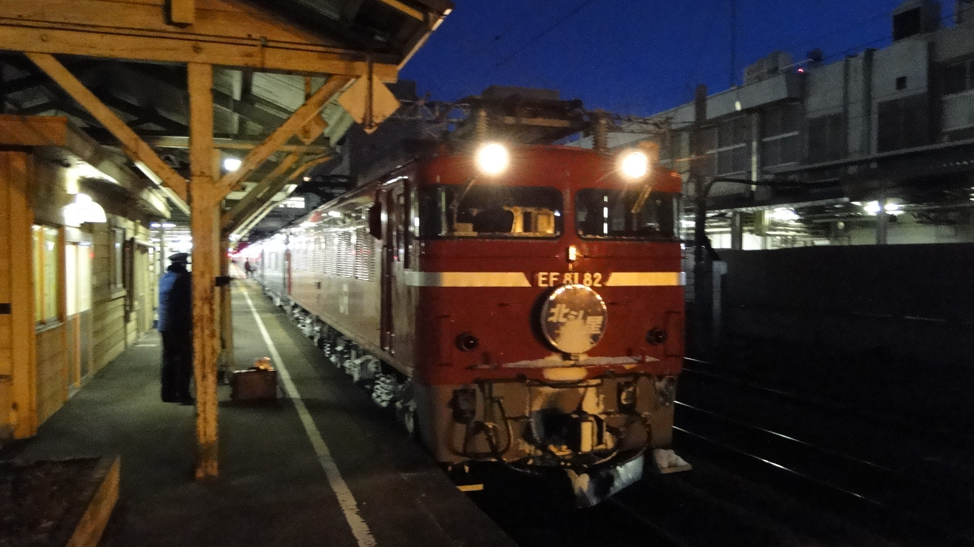
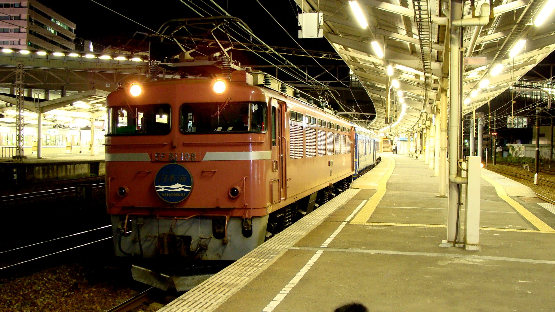
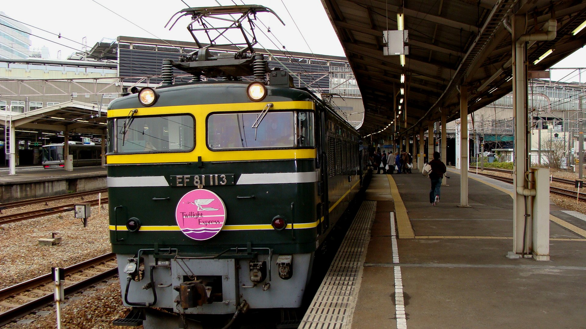
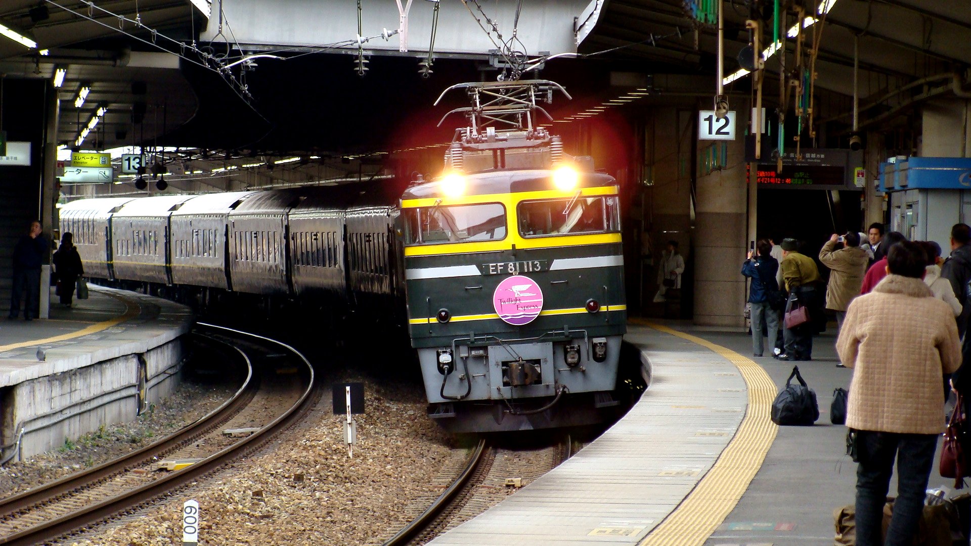
And, of course, if this locomotive really does exist, then please comment and tell me!
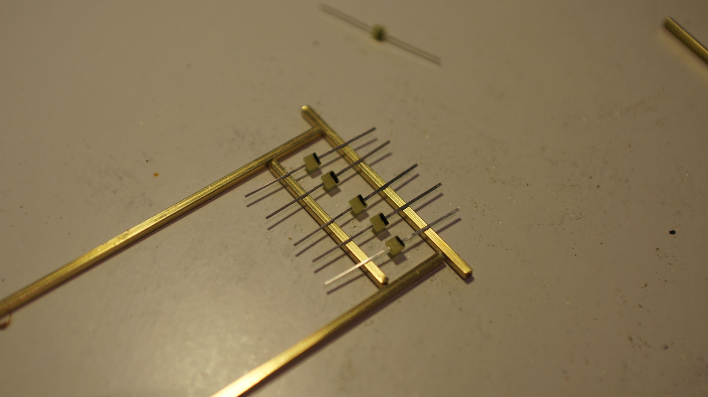
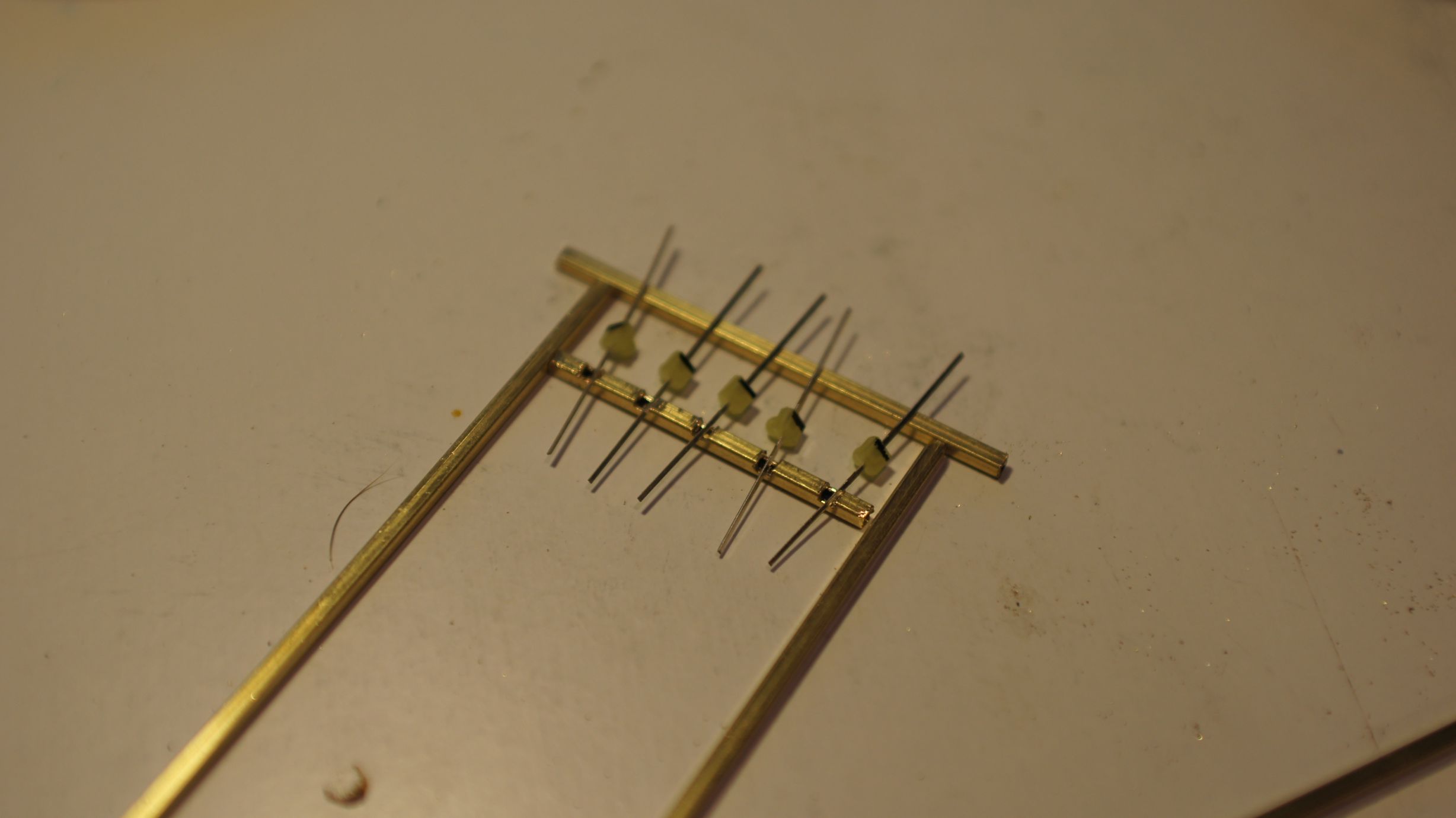
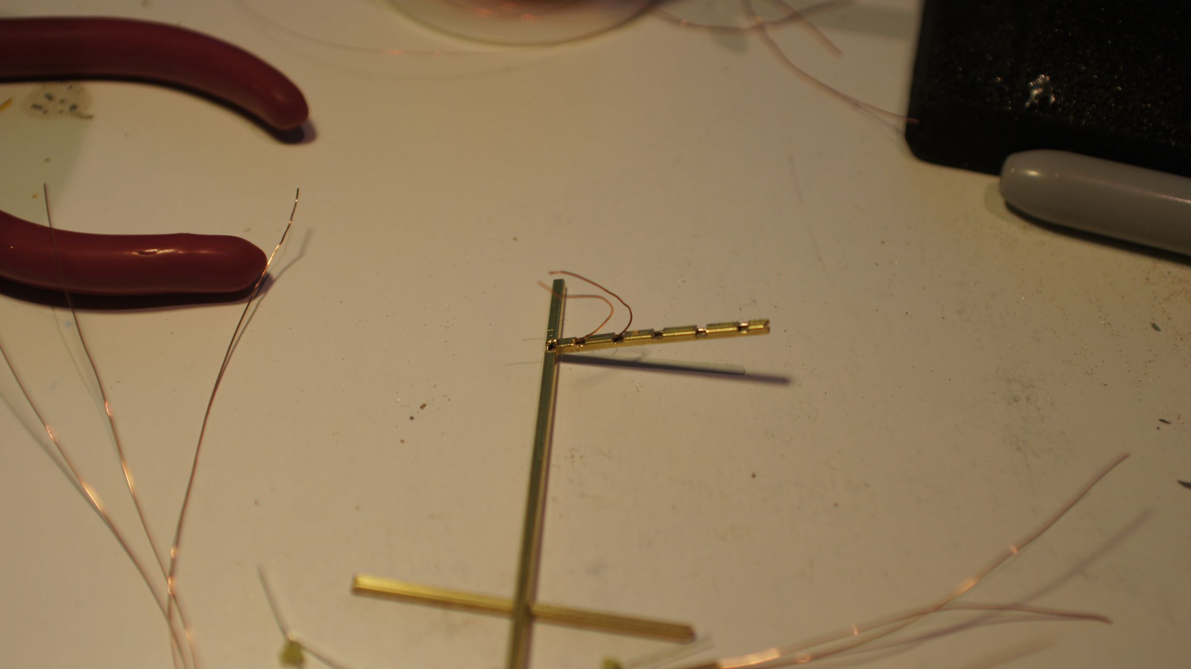
Japanese Level Crossing Lights
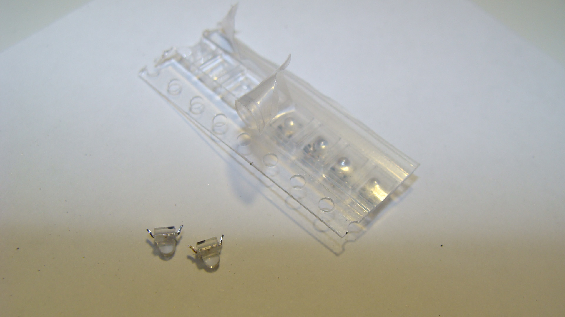
After seeing how small surface-mount LEDs have gotten, and how cheap, I decided I'd grab a few from our local Jaycar Electronics Store and build a Japanese level crossing signal/light.
Ingredients
- Red SMD LEDs
- Metal tubing, hollow, for the main pole. I used brass from the local hobby store.
- Copper 'winding' wire. Used since it's already insulated.
- Soldering equipment.
- Thin cardboard
The process
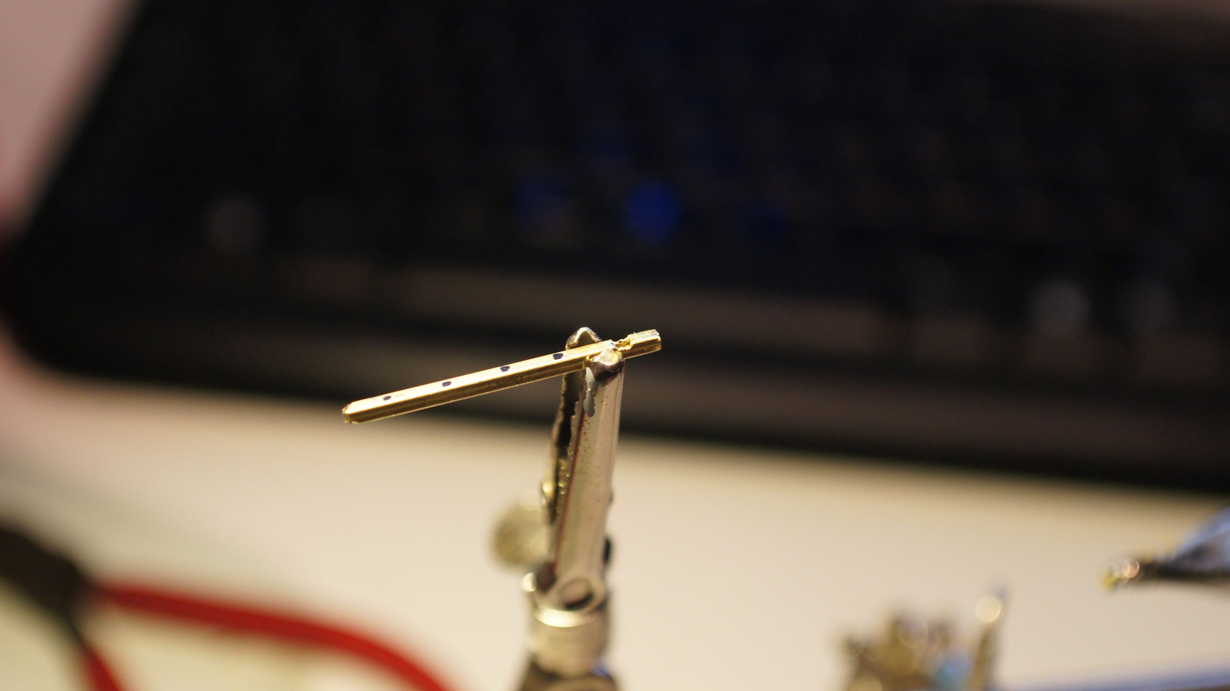
Firstly cut a length of the metal pole and then grind a hole in it behind the area where you intend on soldering the LEDs.
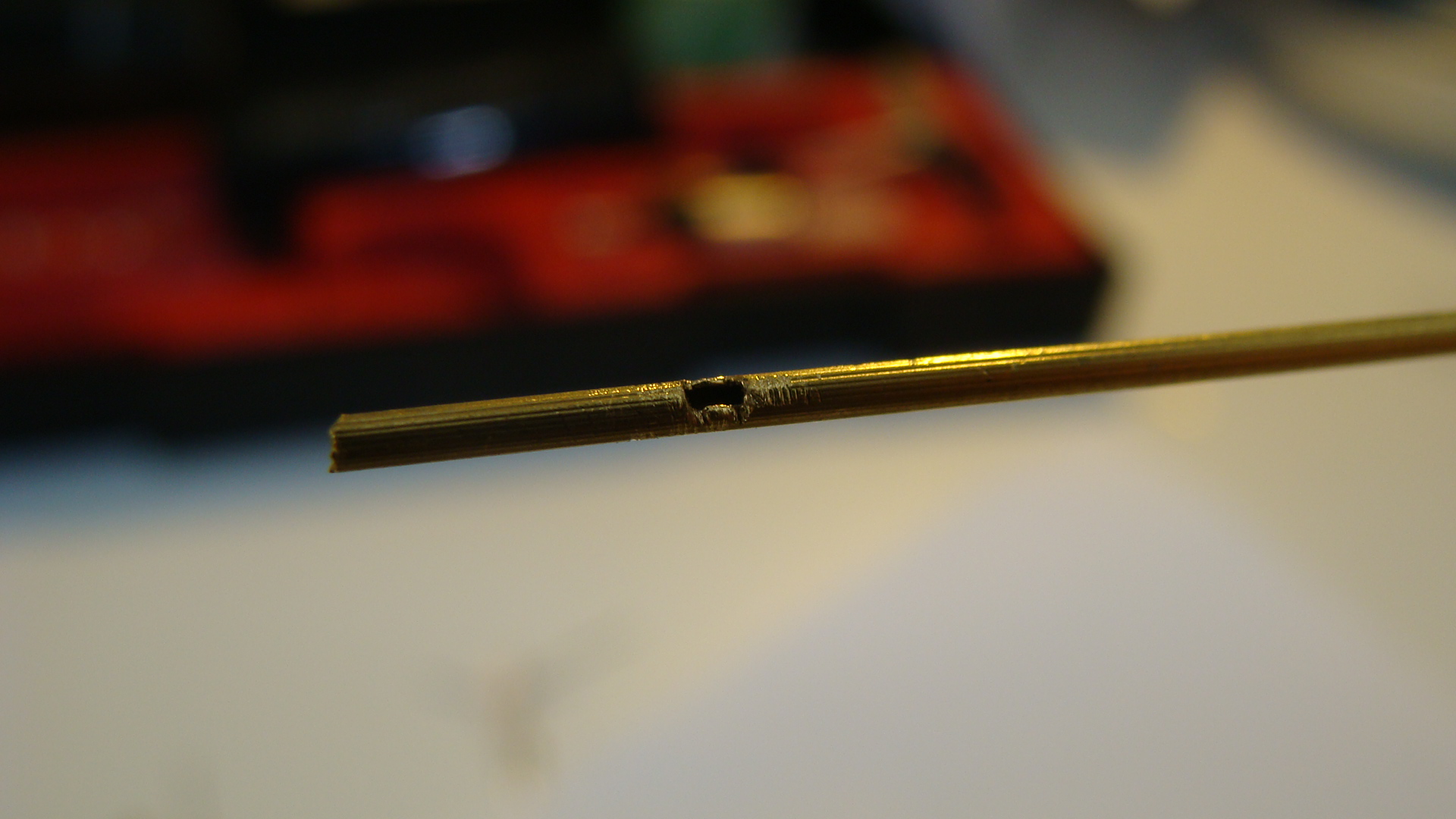
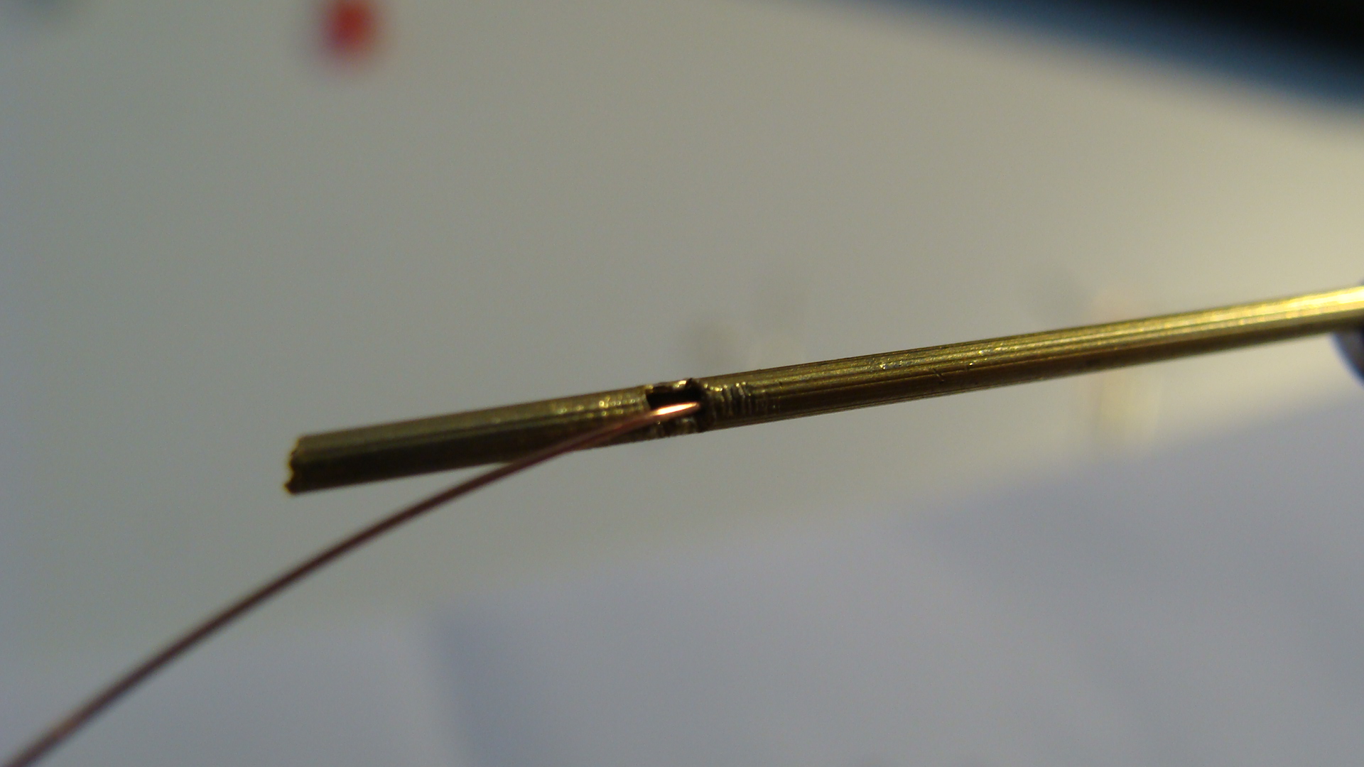
You can see I've run the copper wire through to make sure there are no obstructions. Be careful when doing this as you may well remove the insulation where the wire will rub on the metal pole.
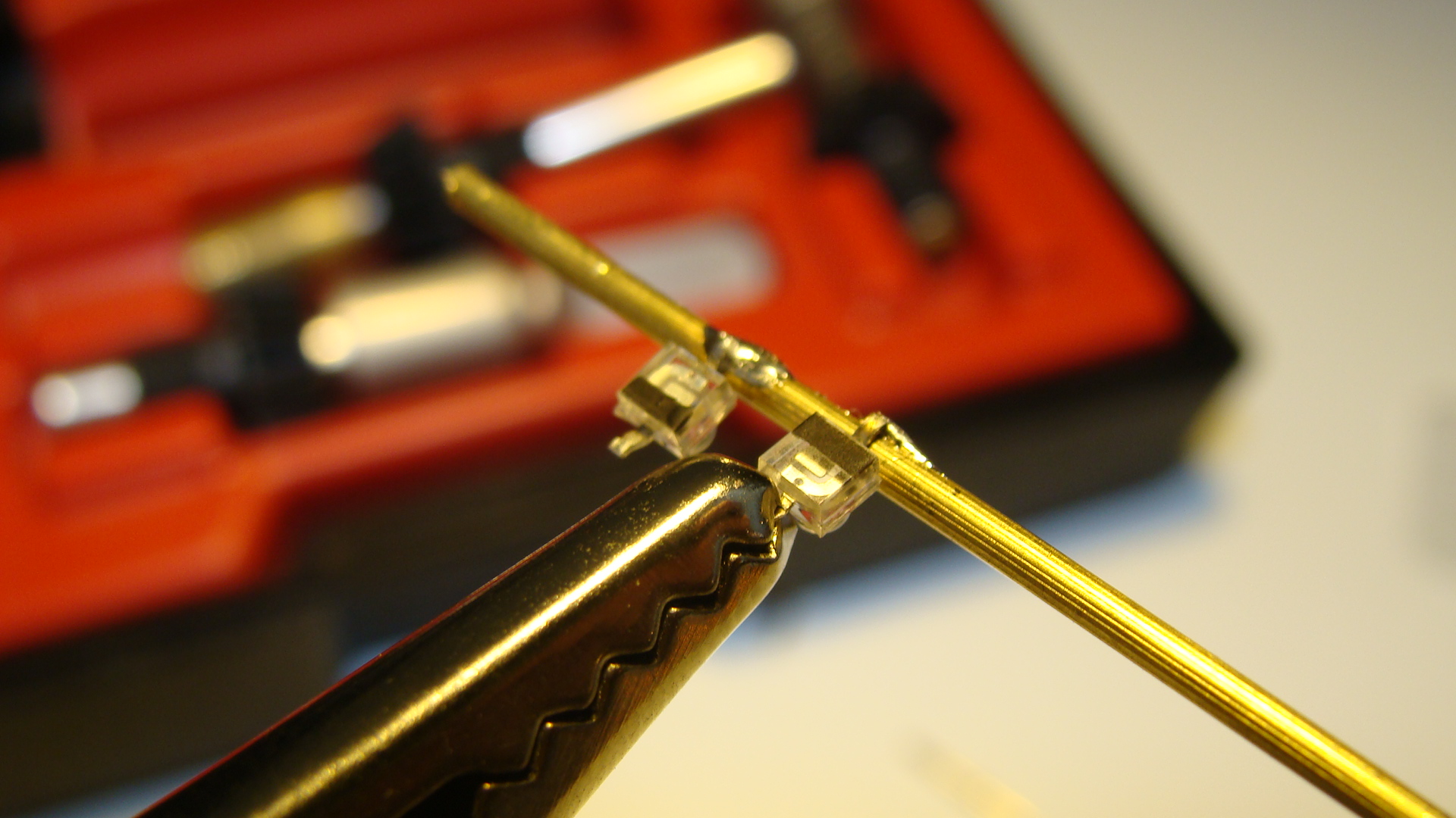
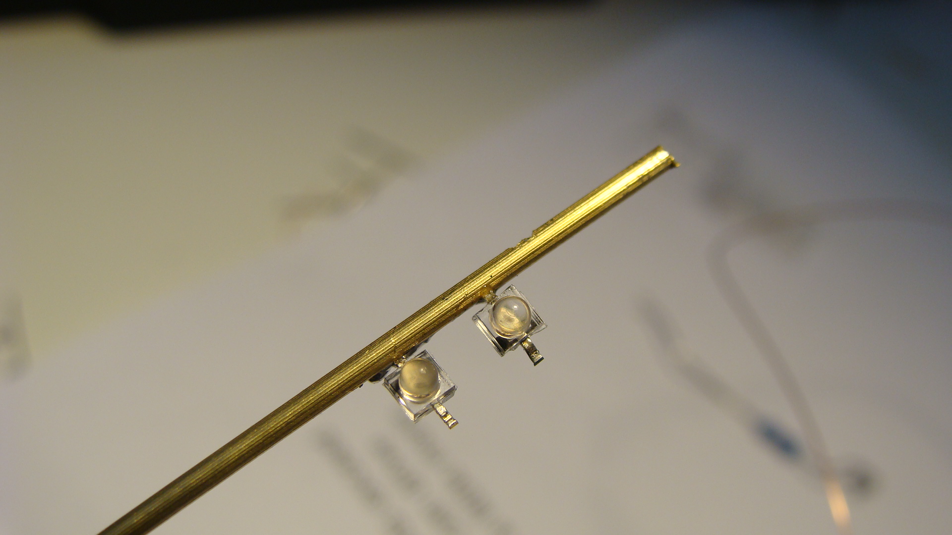
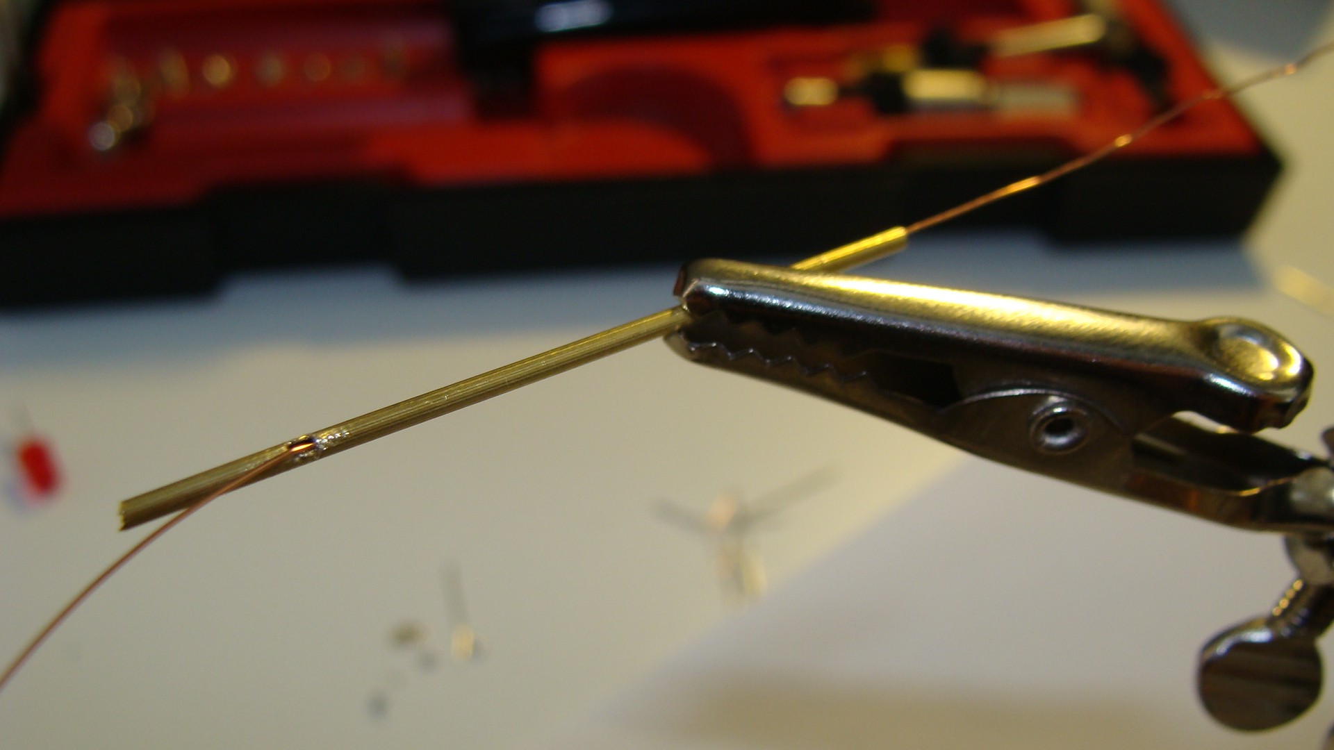
Next rotate the pole around and then solder the LEDs into place. Make sure that one LED is reverse polarity!
Also solder a wire to the base of the main pole.
Run the thin copper wire from the tabs on the LEDs into the hole and then out the bottom of the main pole. Do this after all soldering to avoid melting the insulation.
Cut some thin strips of cardboard and glue them as the cross above the lights.
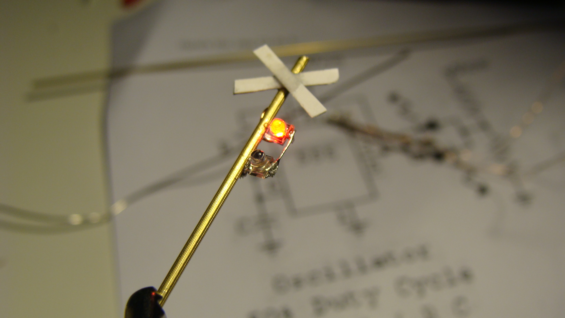
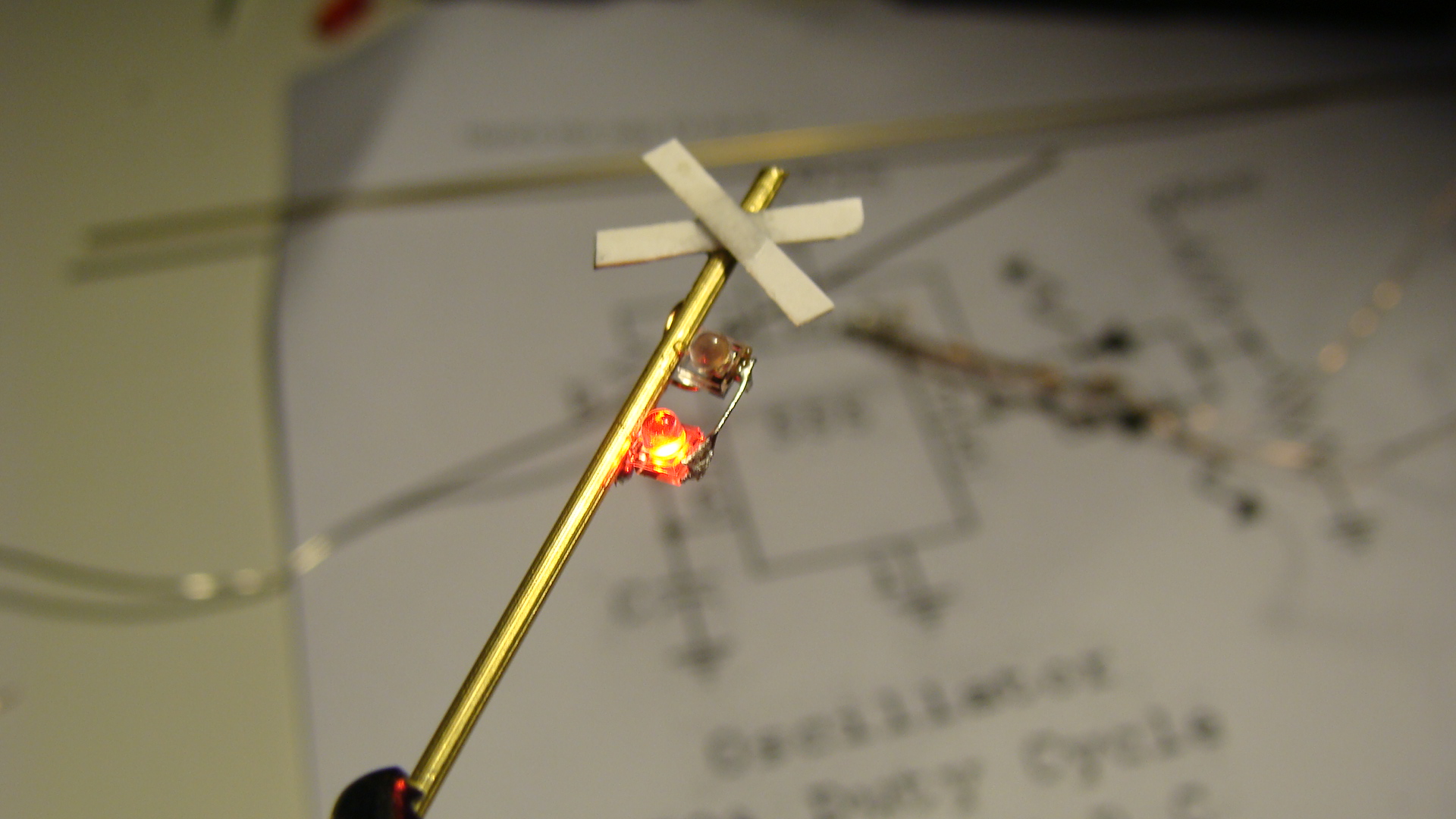
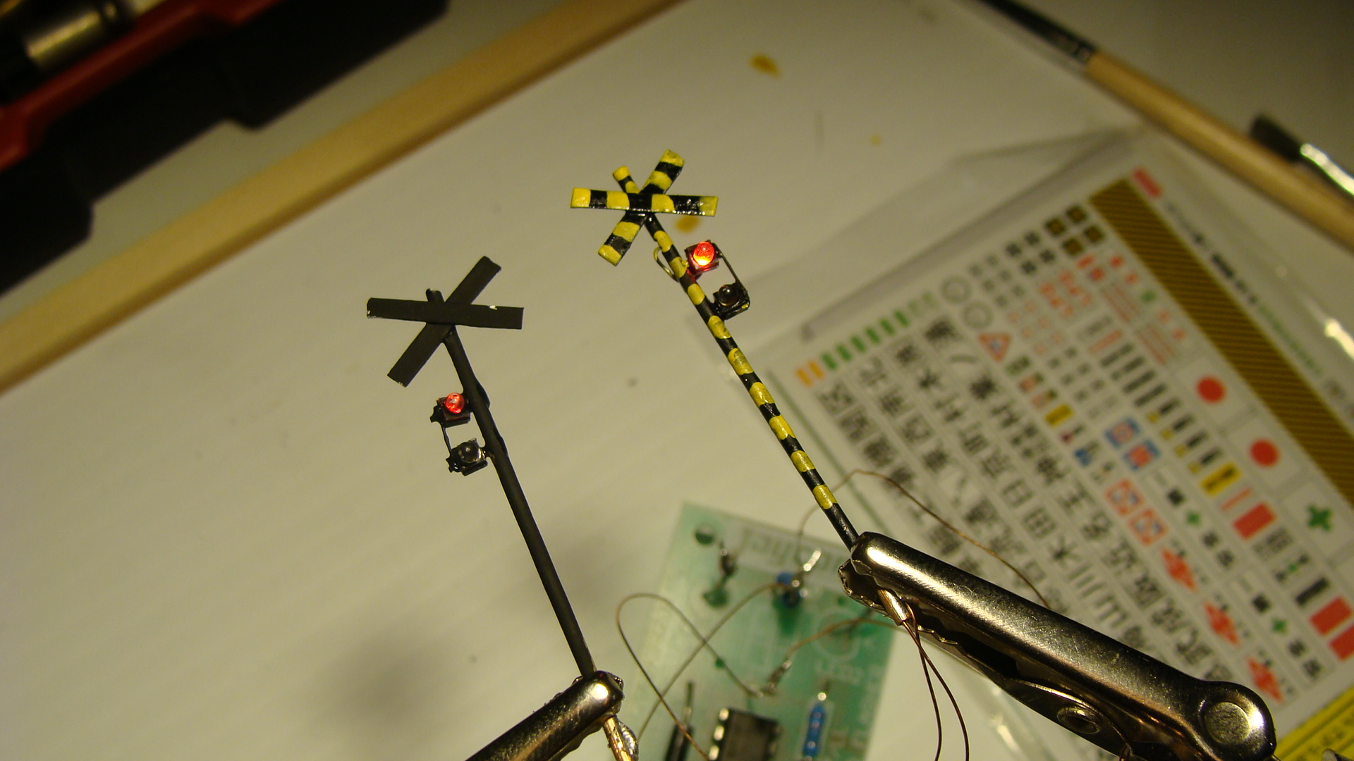
Apply some paint, I was a little sloppy.
The Circuit
Add your favourite flasher circuit.
Make sure that it swaps polarity to only have to use two wires.
And that's about it... Signals next...
Bamboo SL Sound Generator
Early this month, I was in Sydney for a weekend and it co-incided with the AMRA Annual Model Railway Exhibition. I was disappointed to not see the usual Japanese Layout by a well known Australian modeller in the Japanese N Scale realm... but found enough goodies in the 2nd-hand junk boxes to satisfy my need for Japanese stock.
An EF81 (missing one panto and other bits) was still for sale from another seller for $80 and I passed on it again as, although I'm sure it'll run fantastically, I don't want to have to spend the extra money (and time search Poppondetta) for all the missing components.
And then... the find of the day... A, and I quote ”BB サウンドシステム SLドラフトN” or translated to: "BB Sound System SL Draft N". [Note: SL stands for Steam Locomotive in Japanese, they've coined the acronym.] When I saw it, I could only guess that it made SL sounds... and should be towed behind an SL. I asked the price, was told $10 and I didn't even ask if it worked, as I just wanted to get it and test it instantly.
On the train back to the city (2 hour ride) I read the instructions... hah... read them like a picture book! I could read the Katakana.. and that hinted something at a 'Power pack' and 'SCR timing pulse'. I thought I'd just bought a lemon that required some magic to get the chuffing happening... boy was I wrong!
If anyone wants to look at this image and give me a proper translation of it then go ahead... I'll post it here. Otherwise, when I get the time, I'll attempt to type it in to Google translator and see what it spits out. I really should've studied Kanji further after Uni ![]()
Inspecting the Kato WAMU freight car (damn heavy!) I saw that there was a reed switch and a magnet glued to the axle. Primitive technology from Japan... but considering the age of the paper the instructions are on, I'm guessing this whole thing is over 10 years old; but i'm yet to actually research it. Anyway, when rotating the axel you could hear the reed-switch clicking... meaning that it would be the 'pulse' required.
Opening it up, very gently, I found a reasonably dated PCB with quite large components.. but everything fitting nicely. There is a standard (what looked like a microphone) speaker mounted downwards and they've also added weights on the inside of the shell.
Finally, tonight, I put some voltage to the unit. I had to turn my Kato Powerpack up to notch '2' to get it hissing... and it sounds good!... I then pushed it along the tracks and the chuffing started... I realised that I could quickly get it to chuff way too fast and sound like a machine gun. After attaching my MicroAce steamer, I realised the main issue; the voltage required to start the sound was so high that the steamer was already flying. At this speed, although it sounded ok, it was still too fast to be enjoyed. When there was no loco on the tracks and the voltage was high, the sounds were great... you could even lock the reed switch open (at the sweet spot) and the chuff would continue forever... as in when an SL releases pressure at the end of a trip.
I then had a closer look at the circuit board to see if I could drop the required voltage to get the sound moving and something dawned on me... The sound worked in both directions... meaning that the circuitry had to work either way the DC voltage was supplied... this meant it had to have a bridge-rectifier in it already... DCC AC Voltage here I come!!!!
Of course, I ran out of time to test it on DCC and I also have no SLs DCC'd up. My MicroAce steamer seems to have a large enough tender... but I love that thing and don't want to hurt it. It also manages to suck power through it's driving wheels and so it'll be a task to convert it.
Videos!
This is the unit running on DCC. I don't have any steamers converted to DCC yet, so I put it in the middle of my 'Aizu Renewal' set. Apart from grotty wheels and tracks, the sound is great.
These videos haven't aged well!
Random Photos
Search
Tags
Links - Click for details
- Abandoned Rails (Japan)
- AIRLINE (Shinkansen Photography)
- Akihabara Station
- annexpressのブログ
- Australian Model Railway Magazine
- DCC普及協会ホームページ (Japanese DCC)
- Dead Section (Japanese Track Diagrams)
- Delicious Things (Japanese N Scale DCC)
- Densha Wotorou
- Digital Direct for Windows (DCC Server)
- Don's Dream World – AMAZING N Scale Japanese Layout
- Hatena::Diary
- Japanese N-Scale Modeling Forum
- JR Chiisai
- Kaz-T's blog レインボーライン (Rainbow Line)
- LED Resitance Calculator
- Masioka
- Poppondetta Blog
- RailFan Magazine, Japan
- Railmind
- Railway Travelers' Room
- Serenity Valley
- Shashinka Ichiban
- Shuzuku
- Sumida Crossing
- The next station is…
- Tomix N Gauge Track and Japanese N Gauge Trains
- TT Forums (Transport Tycoon Deluxe)
- 名鉄尾西線の貨物列車 (Nagoya: Meitetsu Freight)
- 日本型Nゲージ DCC改造例のご紹介 (Okiraku DCC)
- 泰 茅 轍 道 (Taichi Railway)
- 箱庭登山鉄道製作記 (Hakone-Tozan Layout Blog)
Archive
- July 2026
- May 2026
- April 2026
- March 2026
- February 2026
- January 2026
- November 2025
- October 2025
- September 2025
- August 2025
- July 2025
- June 2025
- February 2025
- January 2025
- November 2024
- September 2024
- August 2024
- July 2024
- June 2024
- May 2024
- April 2024
- March 2024
- February 2024
- December 2023
- October 2023
- September 2023
- August 2023
- July 2023
- June 2023
- May 2023
- April 2023
- March 2023
- December 2022
- November 2022
- October 2022
- April 2022
- March 2022
- February 2022
- January 2022
- December 2021
- November 2021
- September 2021
- August 2021
- July 2021
- May 2021
- March 2021
- February 2021
- January 2021
- October 2020
- September 2020
- August 2020
- July 2020
- June 2020
- May 2020
- April 2020
- March 2020
- January 2020
- December 2019
- November 2019
- October 2019
- September 2019
- August 2019
- July 2019
- June 2019
- April 2019
- March 2019
- February 2019
- January 2019
- December 2018
- November 2018
- October 2018
- September 2018
- August 2018
- July 2018
- June 2018
- May 2018
- April 2018
- March 2018
- January 2018
- December 2017
- November 2017
- October 2017
- September 2017
- August 2017
- July 2017
- June 2017
- May 2017
- March 2017
- February 2017
- January 2017
- December 2016
- November 2016
- October 2016
- September 2016
- August 2016
- July 2016
- June 2016
- May 2016
- February 2016
- November 2015
- October 2015
- September 2015
- August 2015
- July 2015
- June 2015
- May 2015
- April 2015
- March 2015
- February 2015
- January 2015
- December 2014
- November 2014
- August 2014
- July 2014
- May 2014
- April 2014
- March 2014
- December 2013
- November 2013
- October 2013
- June 2013
- August 2012
- April 2012
- March 2012
- February 2012
- November 2011
- October 2011
- September 2011
- July 2011
- June 2011
- May 2011
- April 2011
- March 2011
- February 2011
- January 2011
- December 2010
- November 2010
- October 2010
- September 2010
- August 2010
- June 2010
- May 2010
- April 2010
- March 2010
- February 2010
- January 2010
- December 2009
- November 2009
- October 2009
- August 2009
- January 2009
- December 2008
- November 2008
- October 2008
- September 2008
- July 2008