


 Melbourne BG SCS Train Timetable


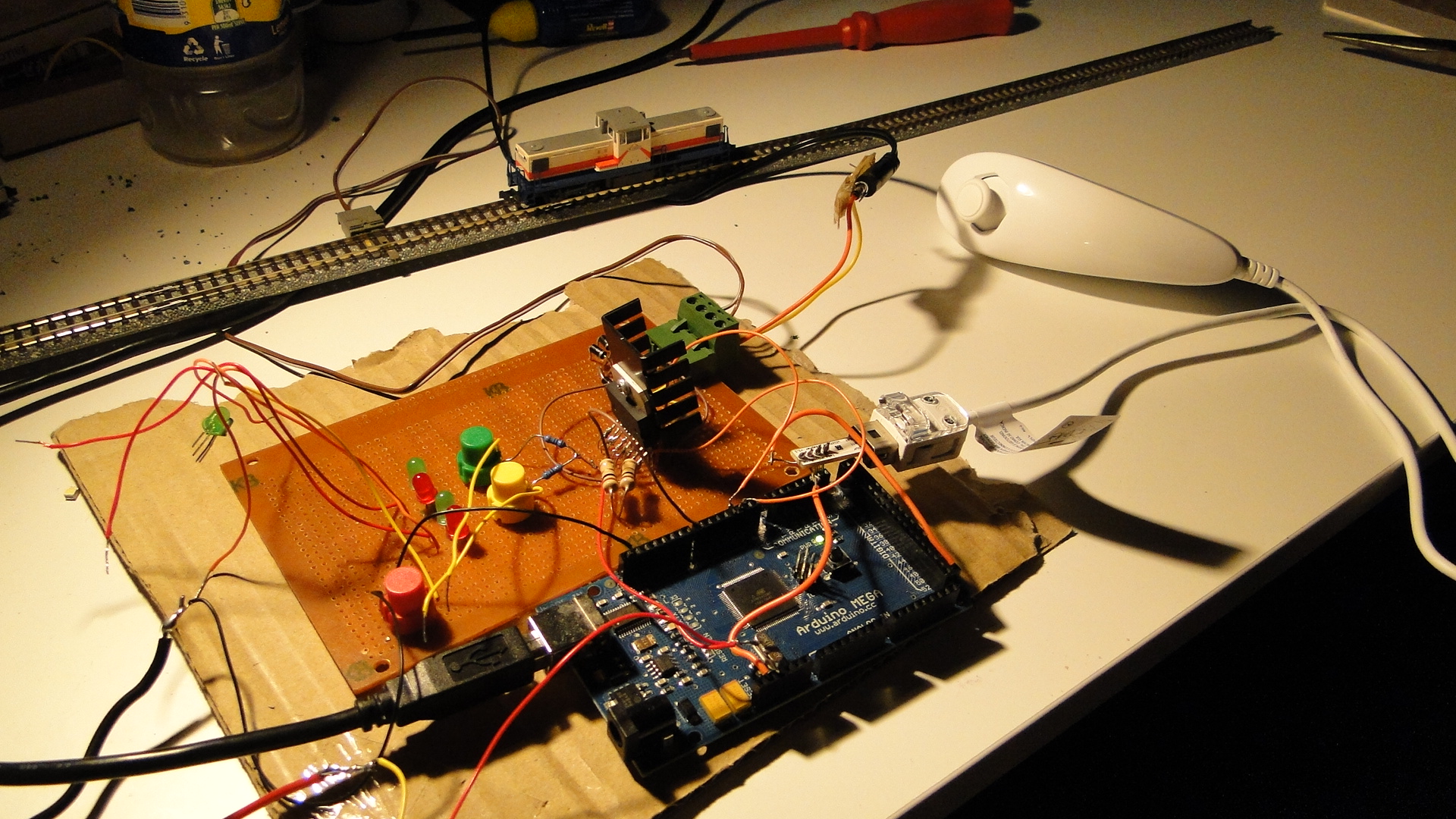
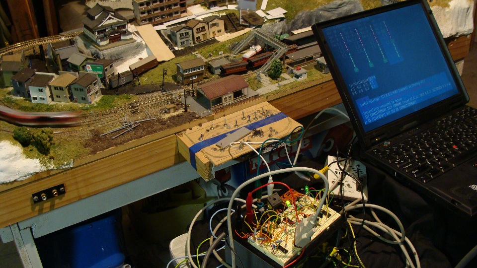
Wii Nunchuck + Arduino Mega + Model Railway = Fun
Well, it had to happen... I bought the header/adapter from here and then, after a little rewiring to fit the Arduino Mega, got the Wii Nunchuck reporting data to my Arduino. Note that this has been done already in multiple places:
- Motor shield and model train!
- Wii Nunchuk Controlled Model Train
- Dawson Station: Wii Nunchuck Train Control?
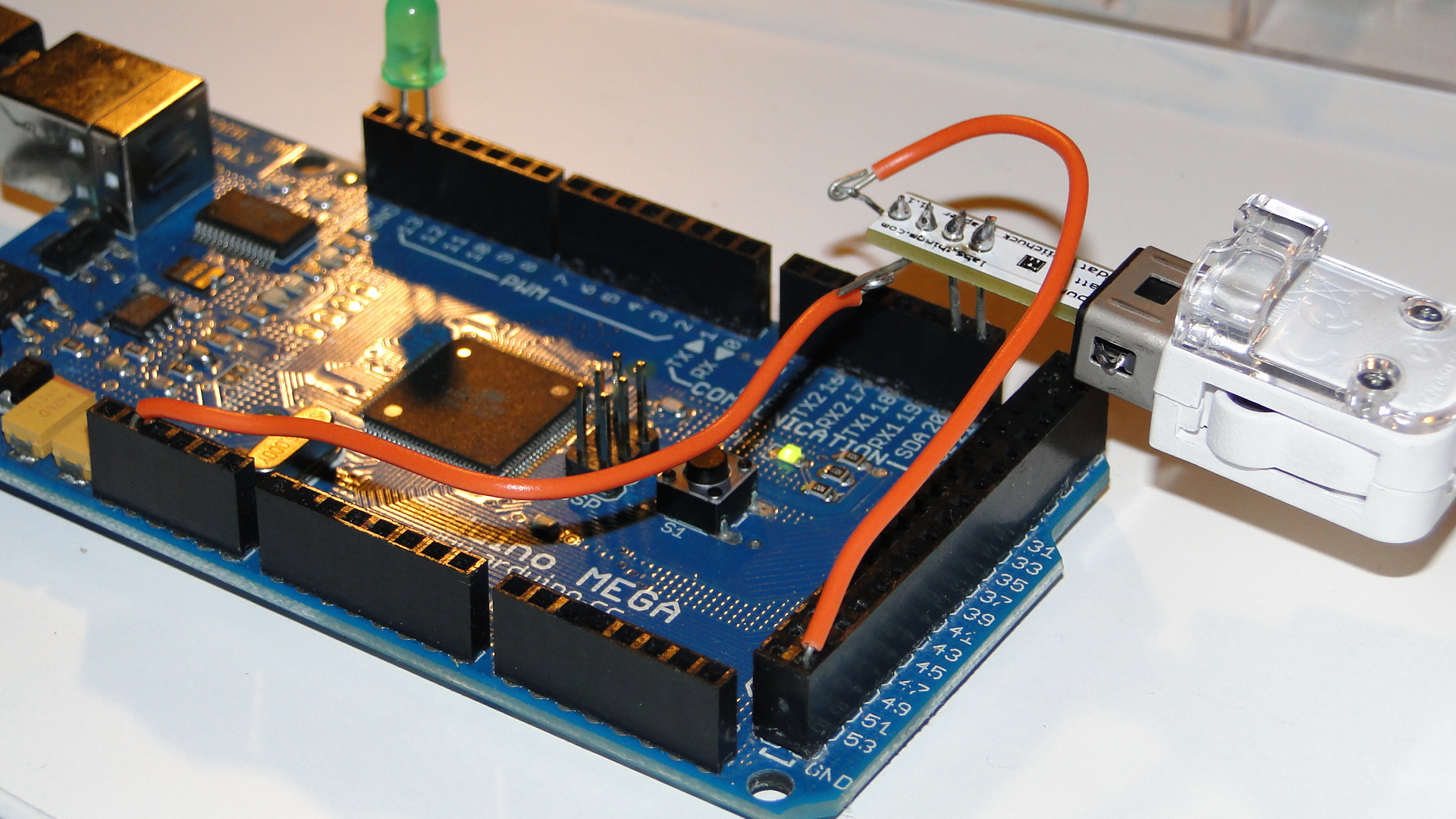
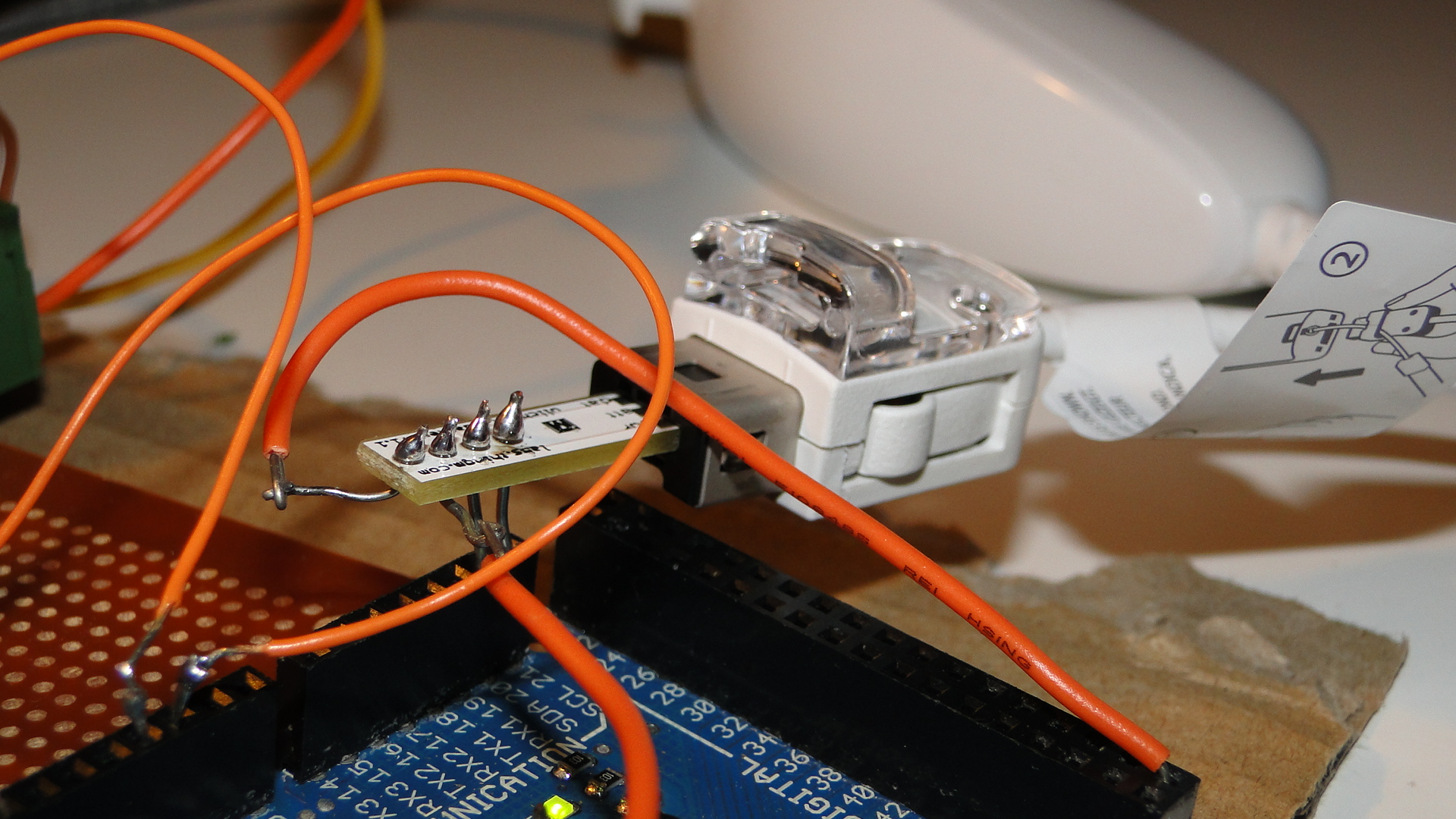
If you have an Arduino Mega, then make sure you have the Negative pin to GND, the Positive to 3.3v, the "d"/"data" pin to SDA20 and the "c"/"clock" pin to SCL 21.
You can then use this code to get the little train moving:
#include <Wire.h>
#include "nunchuck_funcs.h"
#define PWM_INPUT_PIN_1         2
#define PWM_INPUT_PIN_2         3
#define PWM_ENABLE_PIN_1        7
int throttle = 0;
int loop_cnt=0;
void setup() {
  Serial.begin(19200);
  nunchuck_setpowerpins();
  nunchuck_init(); // send the initilization handshake
}
void loop() {
  if( loop_cnt > 100 ) { // every 100 msecs get new data
    loop_cnt = 0;
    nunchuck_get_data();
  }
  loop_cnt++;
  throttle = nunchuck_joyx() - 127;
  if (throttle < 10 && throttle > -10) throttle = 0;
  UpdateTrackPower();
}
void UpdateTrackPower() {
  if (throttle == 0) {
    digitalWrite(PWM_INPUT_PIN_1, LOW);
    digitalWrite(PWM_INPUT_PIN_2, LOW);
  } else {
    if (throttle > 0) {
      digitalWrite(PWM_INPUT_PIN_1, HIGH);
      digitalWrite(PWM_INPUT_PIN_2, LOW);
    } else if (throttle < 0) {
      digitalWrite(PWM_INPUT_PIN_1, LOW);
      digitalWrite(PWM_INPUT_PIN_2, HIGH);
    }
  }
  analogWrite(PWM_ENABLE_PIN_1, abs(throttle));
}
Note that you need to have the L298 Motor controller from the previous post connected to get power to tracks!
Now I just need to think of a cool way to use the buttons on this controller. Currently I just have the top joystick controlling the train on the X axis with center being stopped.
Controlling your trains with an Arduino
A quick introduction to the Arduino
Arduino is an open-source electronics prototyping platform based on flexible, easy-to-use hardware and software. It's intended for artists, designers, hobbyists, and anyone interested in creating interactive objects or environments.
Arduino can sense the environment by receiving input from a variety of sensors and can affect its surroundings by controlling lights, motors, and other actuators. The microcontroller on the board is programmed using the Arduino programming language (based on Wiring) and the Arduino development environment (based on Processing). Arduino projects can be stand-alone or they can communicate with software on running on a computer (e.g. Flash, Processing, MaxMSP).
The boards can be built by hand or purchased preassembled; the software can be downloaded for free. The hardware reference designs (CAD files) are available under an open-source license, you are free to adapt them to your needs
Using it on your Model Railway
So, I recently purchased an Arduino Mega Microcontroller with the intent to control a Model Railway. This article will be the first in a series to show you how to use an Arduino to control different areas of a layout. Our first goal will be to create a controller/throttle with very basic Acceleration/Braking and a 12v DC Pulse Width Modulated output.
Note that this will all be based on DC electronics; this has nothing to do with DCC.
First, here's a list of web resources for controlling a 12v output with the Arduino:
- Basic 12v Output
- AdaFruit Motor Shield - Circuit that plugs directly onto your Arduino and provides outputs
- DIY H-Bridge Add-on
- DC Motor Control Using an H-Bridge and a PIC
- DC Motor Control Using an H-Bridge - Similar to above
- Dual Motor Driver with Arduino using a SN754410NE Quad Half H-Bridge
- L298 Hbridge meets Arduino mega
- PWM with l293/l298 - Provides great information on how to control a H-Bridge
- Controlling a DC motor with the Arduino and L293D
- DC Motor Driver v1.1
- 4A H bridge motor driver using the L298 IC
- Bi-directional Control Of Motors And The H-Bridge
- Others
What I created
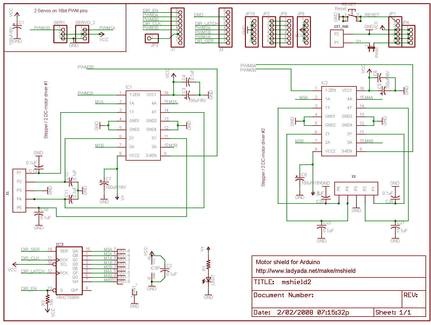
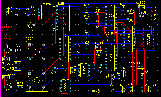
In the end I chose to use the schematics and information from the guys at pyroelectro.com which uses the L298 H-Bridge integrated circuit. My main reasoning was that, although they used a PIC microcontroller, they correctly controlled the L298 with PWM on it's input rather than it's enabling pin. Either way, the PWM signal is still created...
Here's the schematic. I've added a few extra buttons and LEDs and also added a potentiometer for speed control.
Notes:
- The IC is facing towards the viewer (i.e. so that the text on the IC is visible.)
- It's also recommended to use a heatsink!
- Ensure that you connect the ground(GND) on the L298.. It'll overheat and fry if you don't.
- You must use Ultra Fast Diodes for the flyback diodes. More information here
Right, what do you need to know?... The PWM pins are labelled on your Arduino board. By default they output a PWM signal when you feed an analogWrite(pin_number) to them. This creates a pulse that the H-Bridge will respond to. The frequency of this pulse (wave) will then govern the final output voltage to the tracks.
For direction control you either apply digitalWrite(HIGH) to PWM2 and digitalWrite(LOW) to PWM3 or vice versa for the opposite direction. Applying LOW to both pins will stop the output and HIGH to both will short circuit!
I've added S1 and S2 to control my direction. It starts off going 'forward', but pressing S2 will set the direction to backwards. The code is written to gradually stop and then accelerate in the opposite direction. Pressing S1 will then set the direction forwards again and the reverse will occur.
S3 is the emergency stop button. Resetting the throttle to zero will cancel the emergency stop flag.
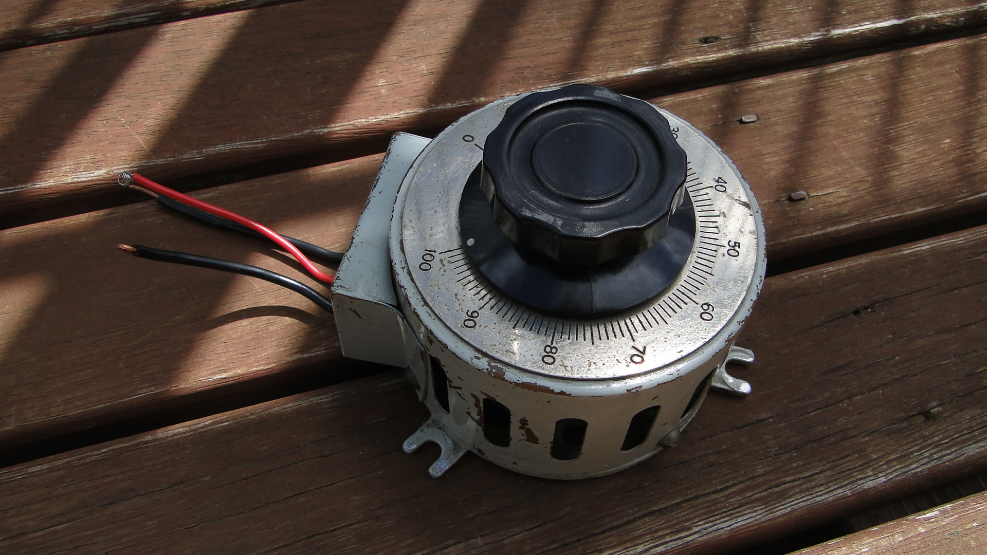
The potentiometer is the throttle... I found a huge one at an antique store down the road and love it. It's rated at 250ohm (no idea what current) and when at '100' the analogRead reports just over 1000. The throttle is only for speed, I really should add a brake lever, as when you return to zero speed the train will only gradually stop. You need to then hit the reverse (or emergency stop) button to stop the train faster.
You'll also require a 12v DC power supply. As your little engines may use up to 1A when starting, make sure this power supply is sufficient. Also, if you don't intend to have the Arduino plugged in to a computer after programming, then this 12v can also supply it (connect all ground wires together!). Just make sure it's a regulated and safe power supply. Note that different Arduinos can handle different voltages! Find your board listed here and then work out the power supply details, otherwise the Arduino Mega details are here (Input max 20v DC).
Source Code
The source code can be downloaded here.
Photos
Here's a few shots of the current set up:
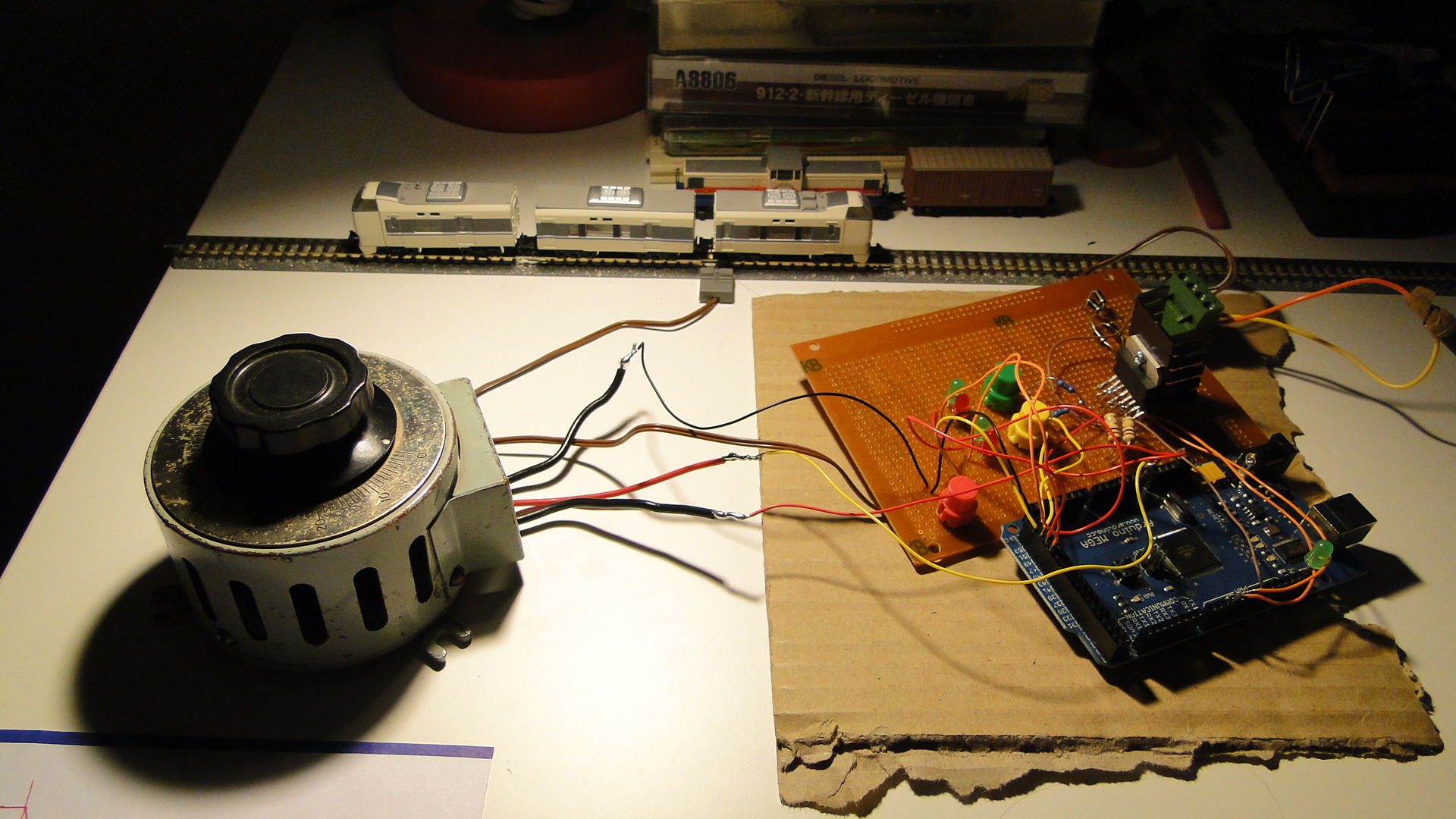
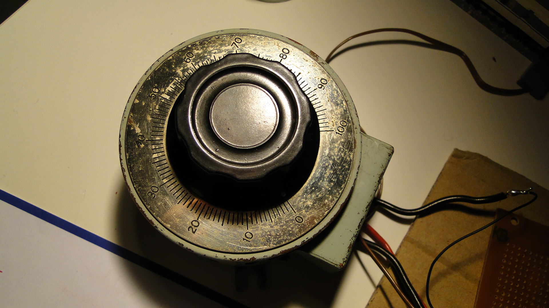
Please do ask any questions you have about this... I've probably skimmed over a lot and am more than happy to update this as necessary. I intend on getting on to more interesting things with this controller as I get the time.
Japanese Level Crossing Lights
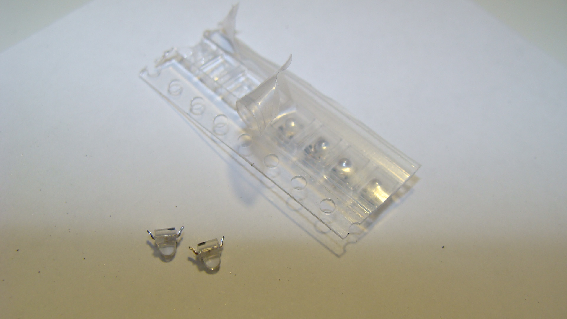
After seeing how small surface-mount LEDs have gotten, and how cheap, I decided I'd grab a few from our local Jaycar Electronics Store and build a Japanese level crossing signal/light.
Ingredients
- Red SMD LEDs
- Metal tubing, hollow, for the main pole. I used brass from the local hobby store.
- Copper 'winding' wire. Used since it's already insulated.
- Soldering equipment.
- Thin cardboard
The process
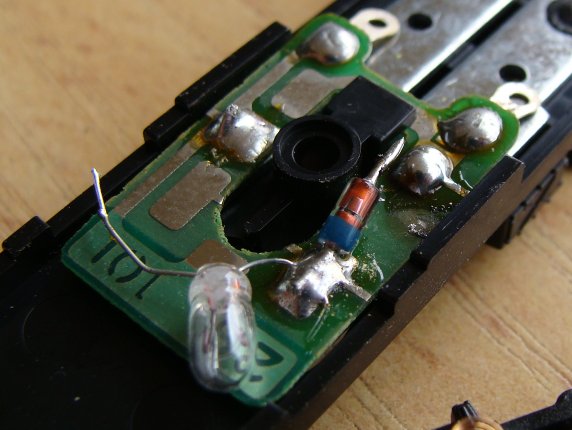
Firstly cut a length of the metal pole and then grind a hole in it behind the area where you intend on soldering the LEDs.
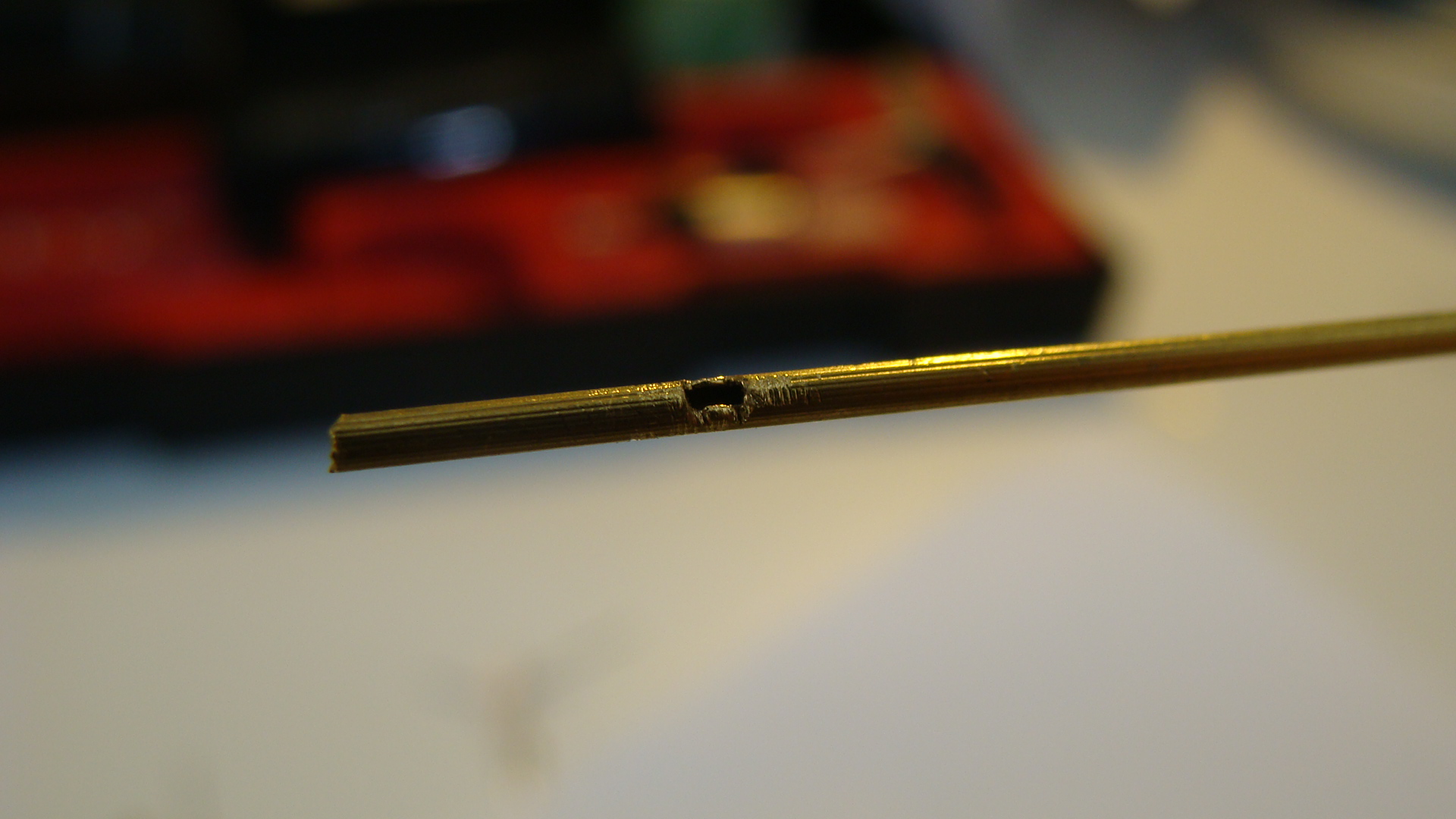
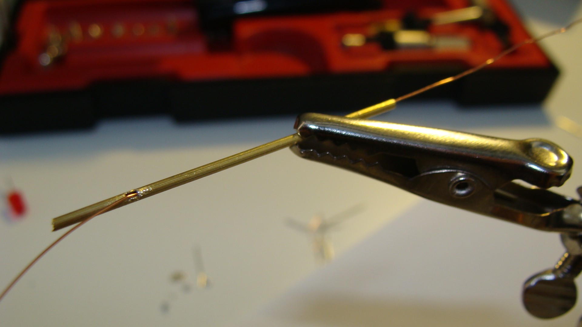
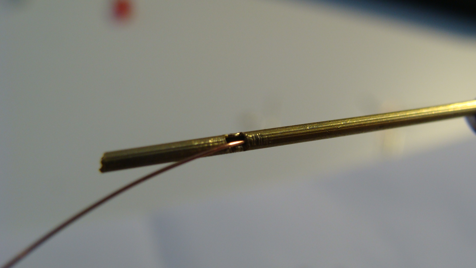
You can see I've run the copper wire through to make sure there are no obstructions. Be careful when doing this as you may well remove the insulation where the wire will rub on the metal pole.
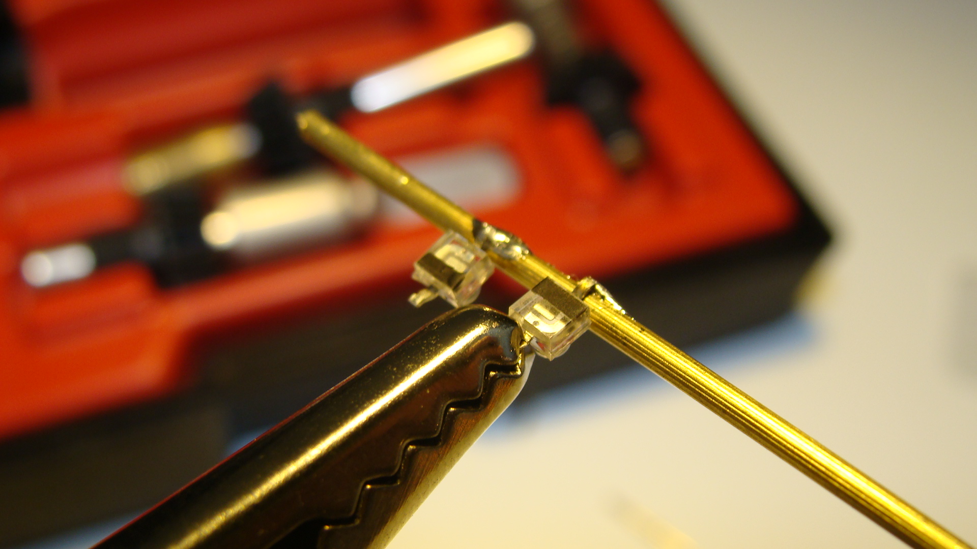
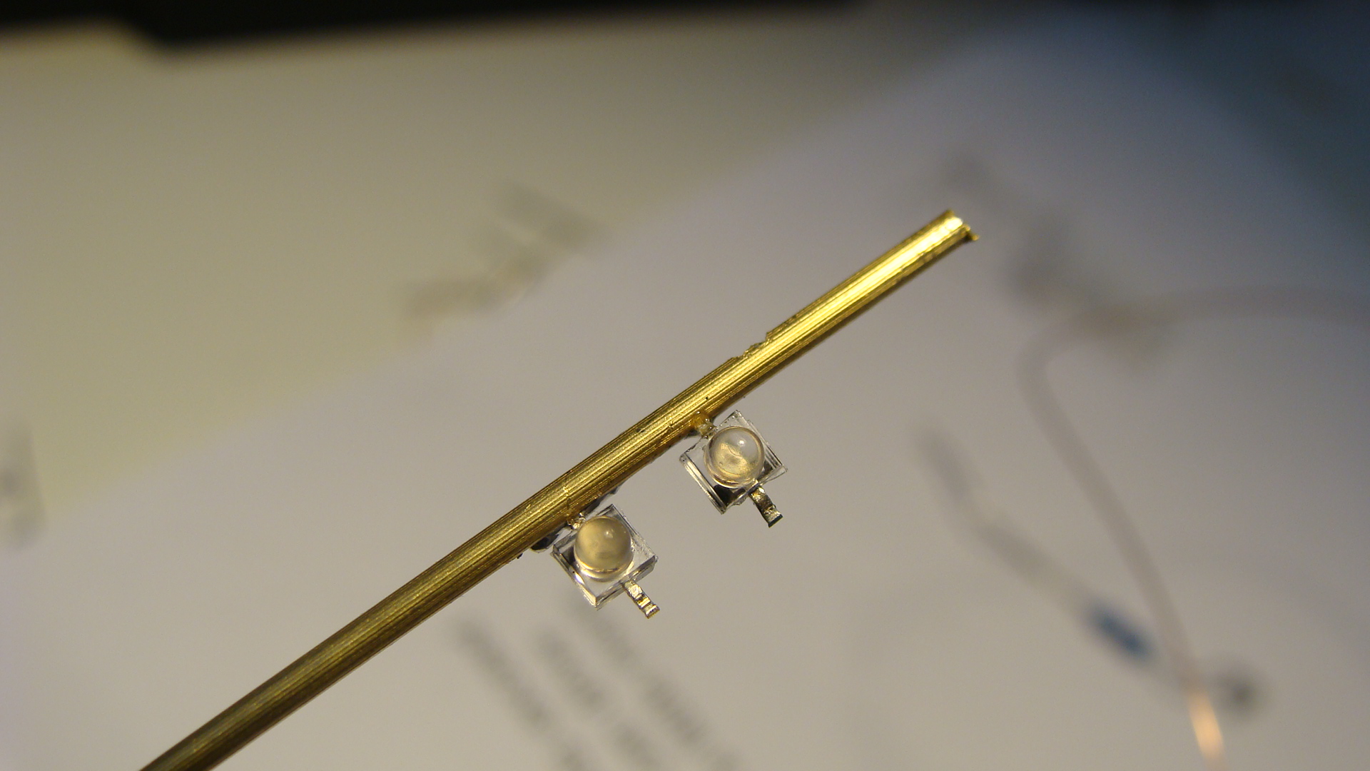
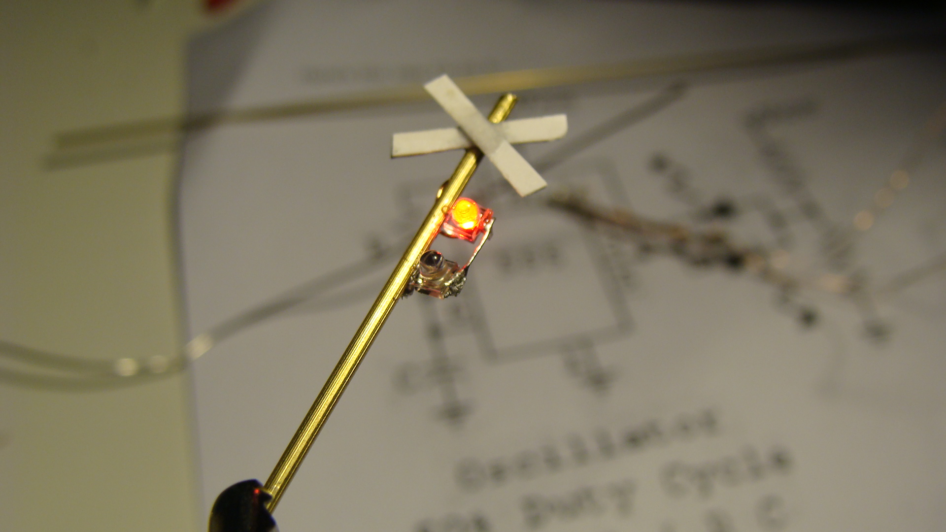
Next rotate the pole around and then solder the LEDs into place. Make sure that one LED is reverse polarity!
Also solder a wire to the base of the main pole.
Run the thin copper wire from the tabs on the LEDs into the hole and then out the bottom of the main pole. Do this after all soldering to avoid melting the insulation.
Cut some thin strips of cardboard and glue them as the cross above the lights.
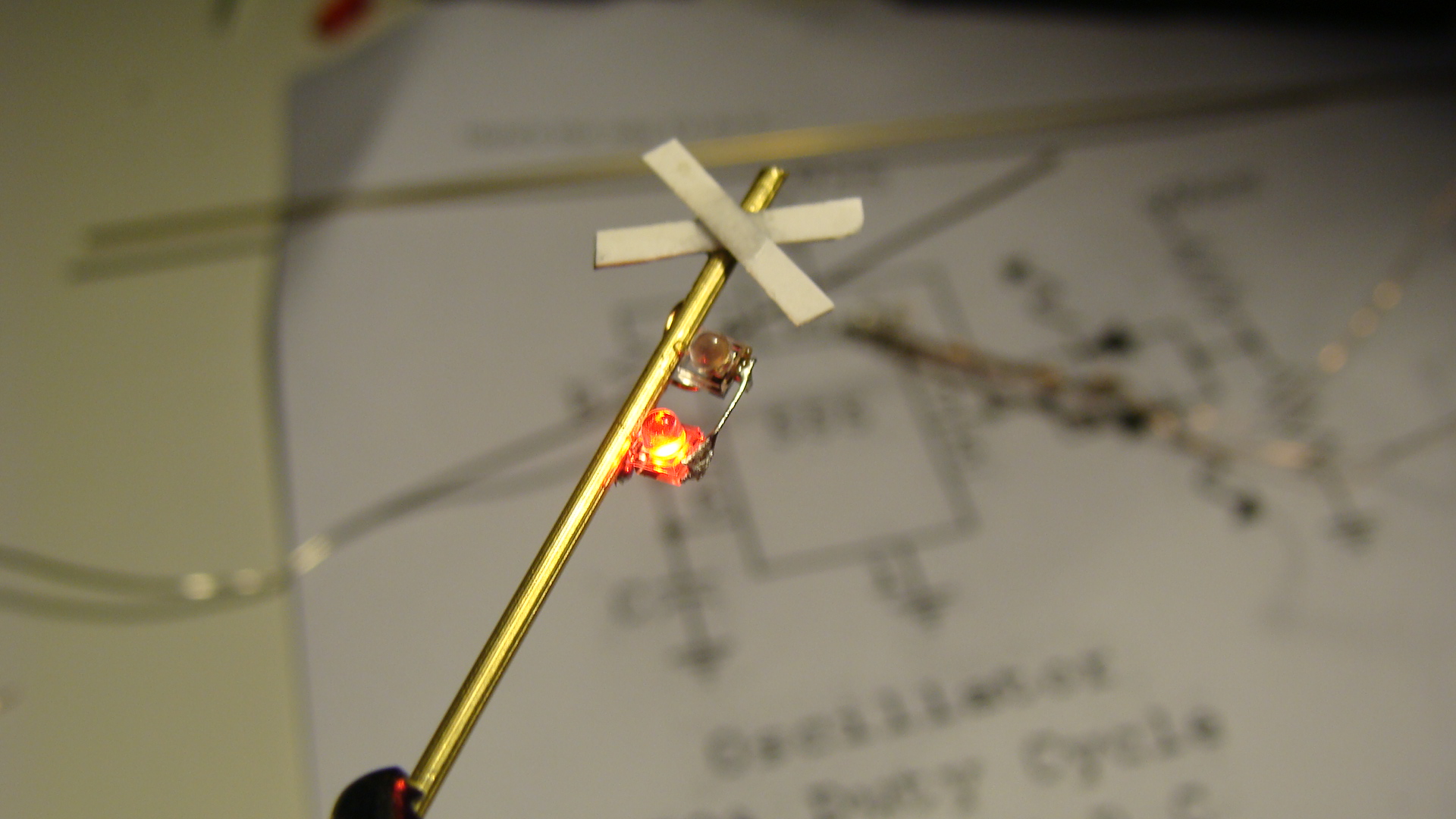
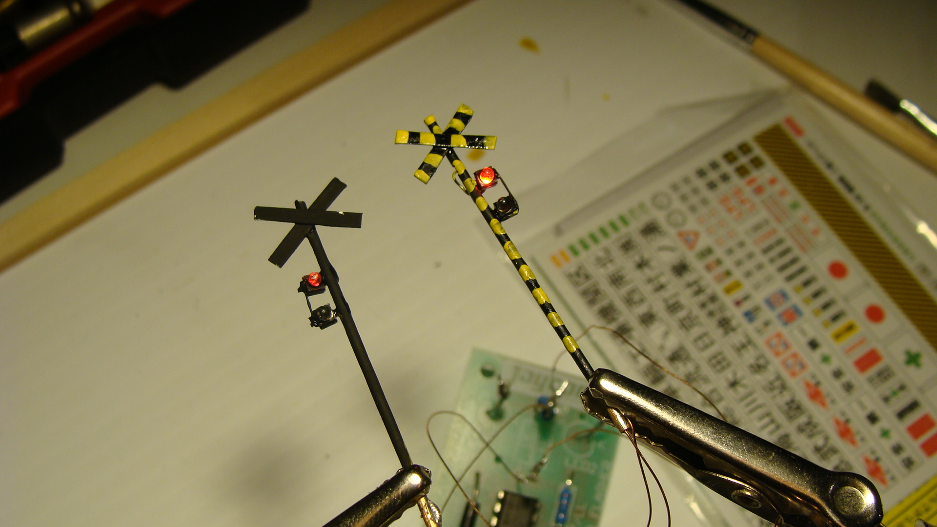
Apply some paint, I was a little sloppy.
The Circuit
Add your favourite flasher circuit.
Make sure that it swaps polarity to only have to use two wires.
And that's about it... Signals next...
Bamboo SL Sound Generator
Early this month, I was in Sydney for a weekend and it co-incided with the AMRA Annual Model Railway Exhibition. I was disappointed to not see the usual Japanese Layout by a well known Australian modeller in the Japanese N Scale realm... but found enough goodies in the 2nd-hand junk boxes to satisfy my need for Japanese stock.
An EF81 (missing one panto and other bits) was still for sale from another seller for $80 and I passed on it again as, although I'm sure it'll run fantastically, I don't want to have to spend the extra money (and time search Poppondetta) for all the missing components.
And then... the find of the day... A, and I quote ”BB サウンドシステム SLドラフトN” or translated to: "BB Sound System SL Draft N". [Note: SL stands for Steam Locomotive in Japanese, they've coined the acronym.] When I saw it, I could only guess that it made SL sounds... and should be towed behind an SL. I asked the price, was told $10 and I didn't even ask if it worked, as I just wanted to get it and test it instantly.
On the train back to the city (2 hour ride) I read the instructions... hah... read them like a picture book! I could read the Katakana.. and that hinted something at a 'Power pack' and 'SCR timing pulse'. I thought I'd just bought a lemon that required some magic to get the chuffing happening... boy was I wrong!
If anyone wants to look at this image and give me a proper translation of it then go ahead... I'll post it here. Otherwise, when I get the time, I'll attempt to type it in to Google translator and see what it spits out. I really should've studied Kanji further after Uni ![]()
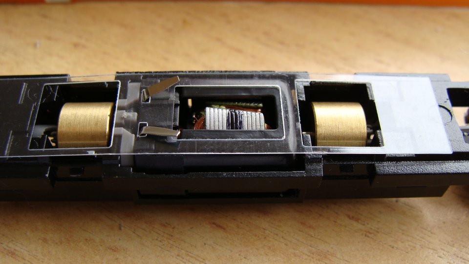
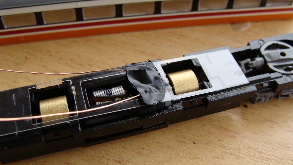
Inspecting the Kato WAMU freight car (damn heavy!) I saw that there was a reed switch and a magnet glued to the axle. Primitive technology from Japan... but considering the age of the paper the instructions are on, I'm guessing this whole thing is over 10 years old; but i'm yet to actually research it. Anyway, when rotating the axel you could hear the reed-switch clicking... meaning that it would be the 'pulse' required.
Opening it up, very gently, I found a reasonably dated PCB with quite large components.. but everything fitting nicely. There is a standard (what looked like a microphone) speaker mounted downwards and they've also added weights on the inside of the shell.
Finally, tonight, I put some voltage to the unit. I had to turn my Kato Powerpack up to notch '2' to get it hissing... and it sounds good!... I then pushed it along the tracks and the chuffing started... I realised that I could quickly get it to chuff way too fast and sound like a machine gun. After attaching my MicroAce steamer, I realised the main issue; the voltage required to start the sound was so high that the steamer was already flying. At this speed, although it sounded ok, it was still too fast to be enjoyed. When there was no loco on the tracks and the voltage was high, the sounds were great... you could even lock the reed switch open (at the sweet spot) and the chuff would continue forever... as in when an SL releases pressure at the end of a trip.
I then had a closer look at the circuit board to see if I could drop the required voltage to get the sound moving and something dawned on me... The sound worked in both directions... meaning that the circuitry had to work either way the DC voltage was supplied... this meant it had to have a bridge-rectifier in it already... DCC AC Voltage here I come!!!!
Of course, I ran out of time to test it on DCC and I also have no SLs DCC'd up. My MicroAce steamer seems to have a large enough tender... but I love that thing and don't want to hurt it. It also manages to suck power through it's driving wheels and so it'll be a task to convert it.
Videos!
This is the unit running on DCC. I don't have any steamers converted to DCC yet, so I put it in the middle of my 'Aizu Renewal' set. Apart from grotty wheels and tracks, the sound is great.
These videos haven't aged well!
DCC “Directional” Lighting without a Decoder
So, you have a 16-Car, 12-Car, 8-Car, 6-Car or 3-Car consist and you want to get the tail/head lights functioning correctly? Of course, you've already installed the expensive decoder in the engine car of the consist and if this is anything like all of the Japanese models I've dealt with, then it's somewhere in the middle and getting the power to the headlights is not really an option.
Ok, So companies like Kato have created smaller, feature-less decoders specifically for headlight and taillights in end cars... these are still the best option... the advantage to what I'm about to show you is that the lights will switch between backwards and forwards.
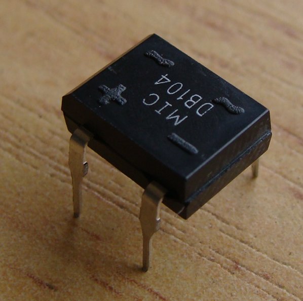
Anyway, if you can't, or are morally obliged not to, install the end-car decoders then you can cheat and install an AC/DC rectifier diode to 'fix' the direction of the train (and lights).
This, of course, means that the train you are going to install this into should really be only every traveling in one direction 'prototypically'. You'll be able to swap the end cars when you want the train to travel in the opposite direction, but this could be tedious and so it is entirely recommended this method only be used for consists where you intend on running them in one direction.
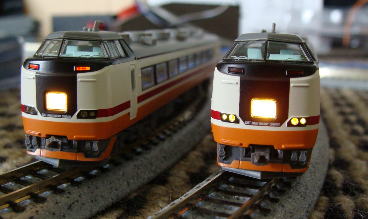
Micro Ace 6-Car "あいづ" KIHA 485系
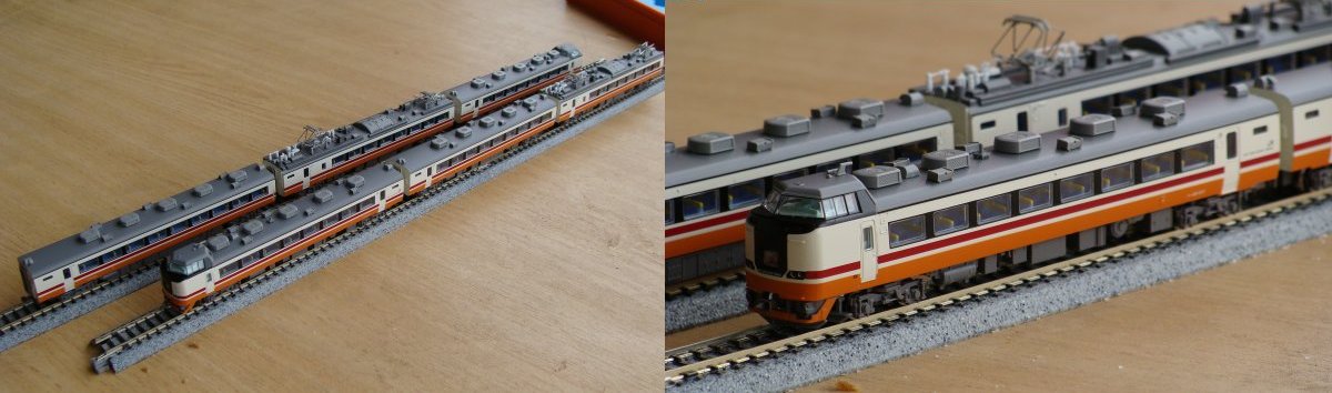
So, as you may have recently seen, I installed a decoder in my 6-Car "あいづ" KIHA 485系。 The engine car was number 3 of 6, so couldn't really get any further into the center... which is a good thing as it means it's nearly pushing as much as it has to pull.
So, I decided as I'd got it at a bargain price, that I wasn't going to fork out too much to make it DCC. I had the decoder in the engine car and wanted the lights to not 'buzz' and function correctly. I intended on having it running in one direction most of the time and could handle swapping the end cars if I wanted it to go the other way.
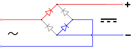
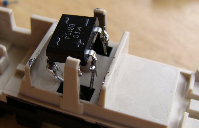
What this meant is that I would get an AC->DC Rectifier (0.84c at the local electronics store) to convert the AC voltage off the tracks to DC.
Once in DC voltage the polarity would be fixed... even if the car was swapped around on the rails.
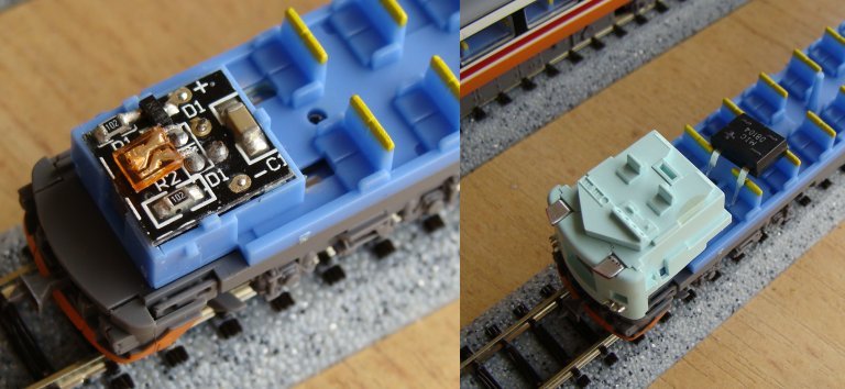
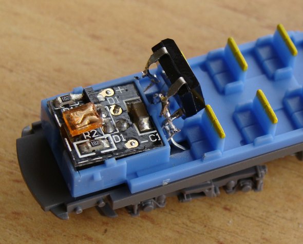
Right, so I removed the old lighting circuit board and bent the pins up that connected with the power rails... I then extended the AC side of the rectifier and pushed the pins into the area where the old contacts used to touch the power rails.
I then soldered up the DC output to the circuit board and threw it on the tracks to test.
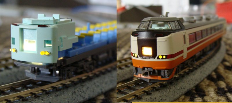
Ok, this worked well... the lights even stayed on constantly after a bit of a wheel clean. Unfortunately, you now cannot 'shutdown' the train in a siding without cutting the power. The other issue now was that the rear car would have the 'Forward Lights' on as well if wired up directly... I therefore had to reverse the wiring after the DC output. I used my 0.25mm 'winding wire' for this.
And then a test...
And that was it... the train was DCC'd and ready to roll... It worked perfectly after this as well.
Twilight Express
I then quickly slapped a Rectifier in my Twilight Express end car and disabled the lighting in the car that sits right next to the engine.
To my surprise... a 12v BULB!... This must been an older set as Martjin had previously mentioned.
...and that was a wrap... yes, it's a mighty cop-out... and those who wish to have functional/switchable head/tail lights should not do this, but it does work and I must admit, does the job for my kinda running (Full Steam Ahead!)
Micro Ace 485 Series “あいづ” 6-Car Decoder Install
I found this for sale on eBay and, although it's JR East, I decided I could do with another 6-Car set.
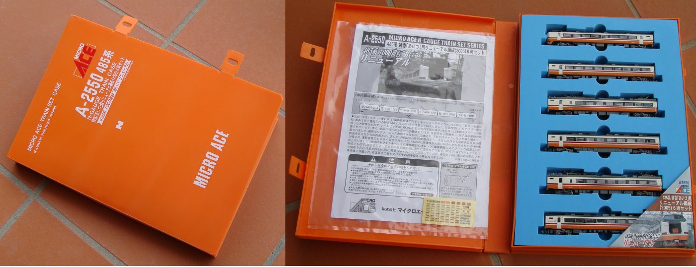
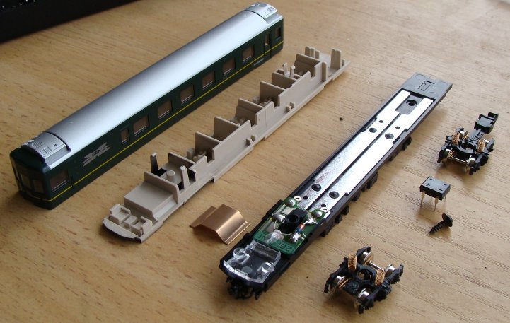
Being my first Micro Ace product, I was extremely impressed with the level of detail. I was also extremely impressed with the electronics on the inside and the way everything just snaps together... of course, this is the same with the greater majority of Japanese model railway products... but this 6-Car set seemed much easier to pull apart.
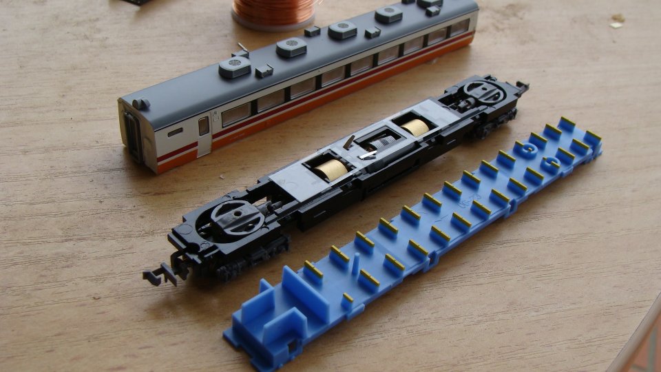
Once apart, it was obvious that the decoder install was going to be very easy... The motor contacts could easily be separated and the power rails were made of copper... solderable! After the copper wire was on.. the wire was lead back up alongside the copper rails to the decoder... wires were also soldered onto the rails to provide power. Finally, the decoder was installed.
Right... lighting... as per any large consist... there is usually a considerable length to the end cars for directional lighting... this usually means that people should install separate decoders in the end cars (high price!) or run wires throughout the cars (ugly!)... so instead, I decided to convert the AC current to DC and force the lights to be in specific directions...
But you'll see that in my next post!
DCC Booster Complete
Ladies and Gentlemen,
I am proud to finally announce that the Booster has been completed and tested.
The final design incorporates the following features:
- Short Circuit Protection with a ~6sec timeout when short detected.
- Two segments per booster rated at 2-3Amp each.
- These can be combined for a total output of ~5Amp.
- Status LEDs to indicate power output on each segment and also overload/short detection on each segment.
- Second Serial Port (DB9) on the rear panel to allow data connection to another booster.
A typical setup of the Booster would be as follows:
The Booster shown above was built in a readily-available Project Box and the next one built will probably not use the same model. I'll be going to the store on the weekend to see exactly what is available as the box used is a little larger than what is really required. Either way, if you still wanted one of these, now is the time to contact me.
Final PCB Board Complete!
Well, Silver Circuits manufactured and delivered my PCB much much quicker than expected and I'm not complaining!
And, last night, after a rush of construction... I couldn't get the board to work... The 'trip' sensors were permanently active! After a 30 minute stare at the circuit design today I'd realised I'd viewed an older circuit schematic when designing the PCB and had put the inputs to the LM339 the wrong way around!
After a quick test to correct this I had the booster operational.
Unfortunately this now means that all boards in this initial run are defective, but I have devised a way to correct the issue without too much hacking. A small veroboard piggy-backed on has allowed me to correct the inputs to the IC.
I was very much relieved once it was all operational. I now need to get the final components (you can see a dodgy-hack of resistors wired on) and the heatsinks in place. Then I'll need to find a neater box to mount it all in and all should be set to go.
PCB Design Complete
Well, after a long fight of finding appropriate software and then design I've finally sent off the final (if not entirely messy) design to the manufacturers...
Sure, it's not as small as I would have liked... but it's all set in stone now. I should see 8pcs on my doorstep in around a fortnight and then I can finally produce a finished product.
I can't wait actually... Last weekend I tested the final prototype on my own layout... which really only allows for around 3 trains running (one on a branch, one stuck in a siding and one on the main) and my battery ran out on the laptop before I had a chance to fully test it all out... either way, the quick test ran perfectly on all accounts:
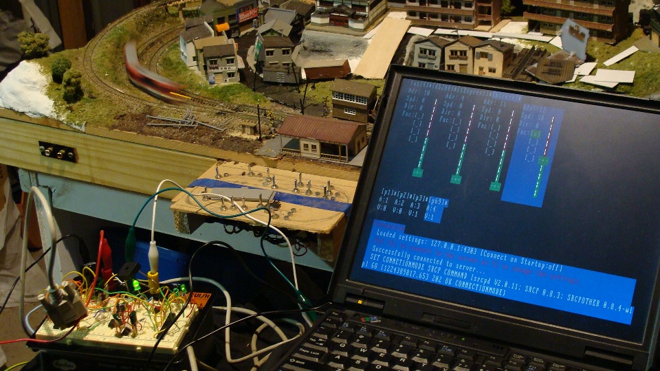
I also purchased two DCC Accessory Decoders from eBay. I coded those in to trainControl (you'll see a few little squares above the console messages and below the train throttles) and they work great. Unfortunately they cannot be wired directly to the Kato UniTrack points (you'll need to wire a few relays in between) but I'm told work well on the Peco points. I didn't get to test them at the time.
The DCC Accessory Decoders did require me to do a bit of fine tuning on the Booster circuit though; it turns out they suck quite a bit of current on power-up to charge their little capacitors. This meant that the initial current draw on the booster was exceeding the trip circuit and the whole system would not power on.
After a little help the 1K2 resistor providing the op-amp comparison voltage was incremented to a 1K4 and everything worked fine.
This made me realise that the circuit will have different requirements for different layouts and so the final design will now incorporate a trimpot (initially set to 1K4) that can be user adjustable [but WILL void warranty] for 'expert users' to adjust.
Anyway... the work continues... everything is now set. I'm quite proud of the entire system and I can't wait to see the final circuit boards!
UPDATE: The boards are already done and on their way (priority) to me... thanks to Silver Circuits!
DCC Booster Prototype Mark II
Ok, hot off the development floor is the Booster Prototype 2.
This now includes short-circuit protection! The final design will have 2 outputs (for two separate segments of track) at 3 Amp each (depending on power supply capabilities.) There are also now 4 status LEDs (Supply Power, Data, Overload, Track Power/Data)... More to come as I finalise the circuit board design.
Random Photos
Search
Tags
Links - Click for details
- Abandoned Rails (Japan)
- AIRLINE (Shinkansen Photography)
- Akihabara Station
- annexpressのブログ
- Australian Model Railway Magazine
- DCC普及協会ホームページ (Japanese DCC)
- Dead Section (Japanese Track Diagrams)
- Delicious Things (Japanese N Scale DCC)
- Densha Wotorou
- Digital Direct for Windows (DCC Server)
- Don's Dream World – AMAZING N Scale Japanese Layout
- Hatena::Diary
- Japanese N-Scale Modeling Forum
- JR Chiisai
- Kaz-T's blog レインボーライン (Rainbow Line)
- LED Resitance Calculator
- Masioka
- Poppondetta Blog
- RailFan Magazine, Japan
- Railmind
- Railway Travelers' Room
- Serenity Valley
- Shashinka Ichiban
- Shuzuku
- Sumida Crossing
- The next station is…
- Tomix N Gauge Track and Japanese N Gauge Trains
- TT Forums (Transport Tycoon Deluxe)
- 名鉄尾西線の貨物列車 (Nagoya: Meitetsu Freight)
- 日本型Nゲージ DCC改造例のご紹介 (Okiraku DCC)
- 泰 茅 轍 道 (Taichi Railway)
- 箱庭登山鉄道製作記 (Hakone-Tozan Layout Blog)
Archive
- July 2026
- May 2026
- April 2026
- March 2026
- February 2026
- January 2026
- November 2025
- October 2025
- September 2025
- August 2025
- July 2025
- June 2025
- February 2025
- January 2025
- November 2024
- September 2024
- August 2024
- July 2024
- June 2024
- May 2024
- April 2024
- March 2024
- February 2024
- December 2023
- October 2023
- September 2023
- August 2023
- July 2023
- June 2023
- May 2023
- April 2023
- March 2023
- December 2022
- November 2022
- October 2022
- April 2022
- March 2022
- February 2022
- January 2022
- December 2021
- November 2021
- September 2021
- August 2021
- July 2021
- May 2021
- March 2021
- February 2021
- January 2021
- October 2020
- September 2020
- August 2020
- July 2020
- June 2020
- May 2020
- April 2020
- March 2020
- January 2020
- December 2019
- November 2019
- October 2019
- September 2019
- August 2019
- July 2019
- June 2019
- April 2019
- March 2019
- February 2019
- January 2019
- December 2018
- November 2018
- October 2018
- September 2018
- August 2018
- July 2018
- June 2018
- May 2018
- April 2018
- March 2018
- January 2018
- December 2017
- November 2017
- October 2017
- September 2017
- August 2017
- July 2017
- June 2017
- May 2017
- March 2017
- February 2017
- January 2017
- December 2016
- November 2016
- October 2016
- September 2016
- August 2016
- July 2016
- June 2016
- May 2016
- February 2016
- November 2015
- October 2015
- September 2015
- August 2015
- July 2015
- June 2015
- May 2015
- April 2015
- March 2015
- February 2015
- January 2015
- December 2014
- November 2014
- August 2014
- July 2014
- May 2014
- April 2014
- March 2014
- December 2013
- November 2013
- October 2013
- June 2013
- August 2012
- April 2012
- March 2012
- February 2012
- November 2011
- October 2011
- September 2011
- July 2011
- June 2011
- May 2011
- April 2011
- March 2011
- February 2011
- January 2011
- December 2010
- November 2010
- October 2010
- September 2010
- August 2010
- June 2010
- May 2010
- April 2010
- March 2010
- February 2010
- January 2010
- December 2009
- November 2009
- October 2009
- August 2009
- January 2009
- December 2008
- November 2008
- October 2008
- September 2008
- July 2008