


 Melbourne BG SCS Train Timetable


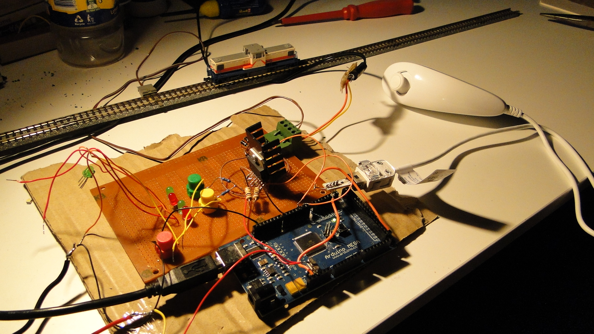
Wii Nunchuck + Arduino Mega + Model Railway = Fun
Well, it had to happen... I bought the header/adapter from here and then, after a little rewiring to fit the Arduino Mega, got the Wii Nunchuck reporting data to my Arduino. Note that this has been done already in multiple places:
- Motor shield and model train!
- Wii Nunchuk Controlled Model Train
- Dawson Station: Wii Nunchuck Train Control?
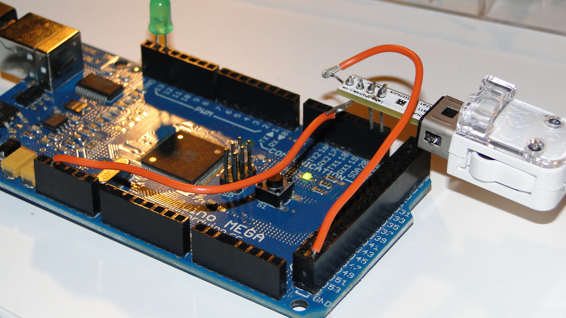
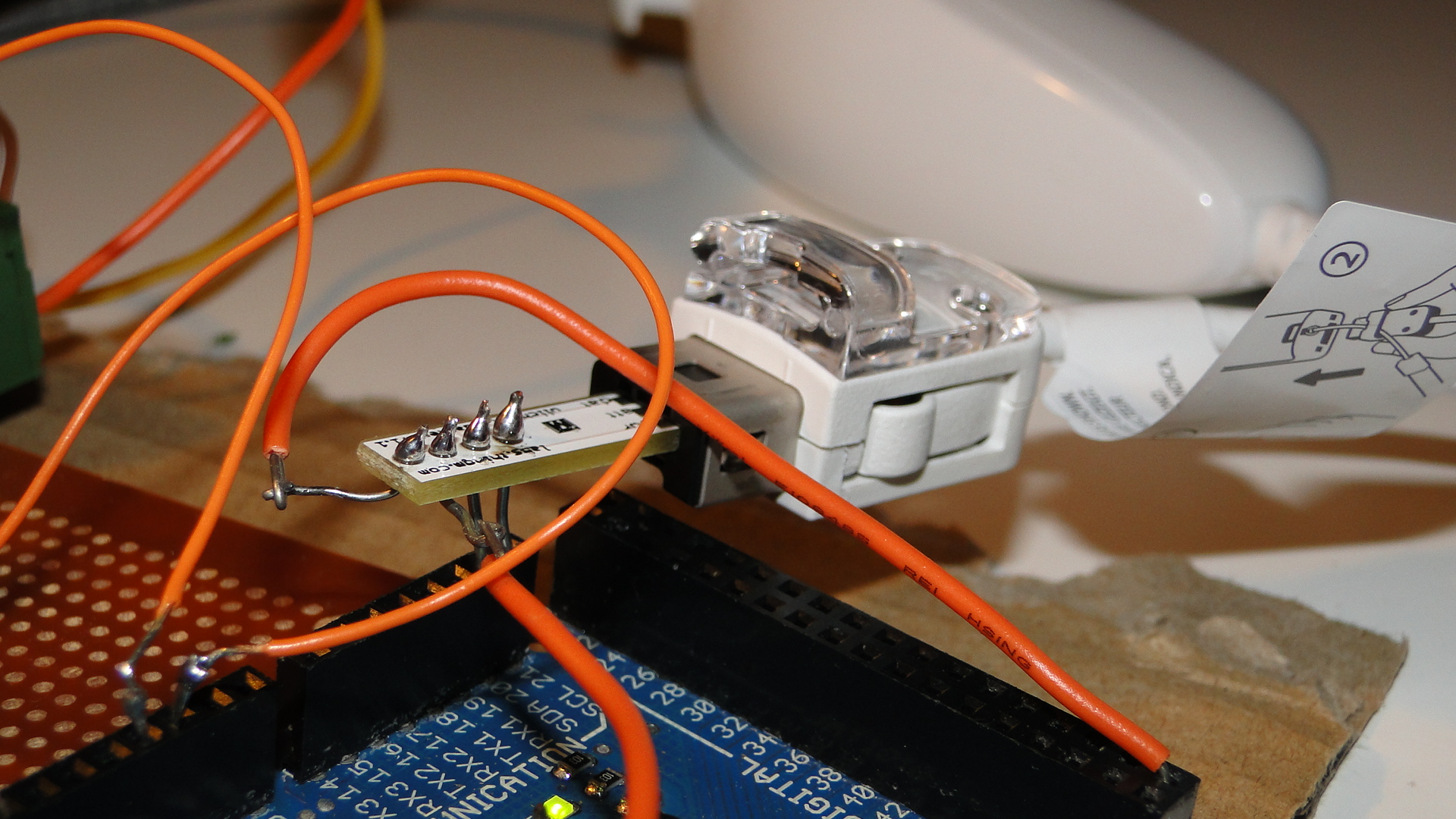
If you have an Arduino Mega, then make sure you have the Negative pin to GND, the Positive to 3.3v, the "d"/"data" pin to SDA20 and the "c"/"clock" pin to SCL 21.
You can then use this code to get the little train moving:
#include <Wire.h>
#include "nunchuck_funcs.h"
#define PWM_INPUT_PIN_1         2
#define PWM_INPUT_PIN_2         3
#define PWM_ENABLE_PIN_1        7
int throttle = 0;
int loop_cnt=0;
void setup() {
  Serial.begin(19200);
  nunchuck_setpowerpins();
  nunchuck_init(); // send the initilization handshake
}
void loop() {
  if( loop_cnt > 100 ) { // every 100 msecs get new data
    loop_cnt = 0;
    nunchuck_get_data();
  }
  loop_cnt++;
  throttle = nunchuck_joyx() - 127;
  if (throttle < 10 && throttle > -10) throttle = 0;
  UpdateTrackPower();
}
void UpdateTrackPower() {
  if (throttle == 0) {
    digitalWrite(PWM_INPUT_PIN_1, LOW);
    digitalWrite(PWM_INPUT_PIN_2, LOW);
  } else {
    if (throttle > 0) {
      digitalWrite(PWM_INPUT_PIN_1, HIGH);
      digitalWrite(PWM_INPUT_PIN_2, LOW);
    } else if (throttle < 0) {
      digitalWrite(PWM_INPUT_PIN_1, LOW);
      digitalWrite(PWM_INPUT_PIN_2, HIGH);
    }
  }
  analogWrite(PWM_ENABLE_PIN_1, abs(throttle));
}
Note that you need to have the L298 Motor controller from the previous post connected to get power to tracks!
Now I just need to think of a cool way to use the buttons on this controller. Currently I just have the top joystick controlling the train on the X axis with center being stopped.
Controlling your trains with an Arduino
A quick introduction to the Arduino
Arduino is an open-source electronics prototyping platform based on flexible, easy-to-use hardware and software. It's intended for artists, designers, hobbyists, and anyone interested in creating interactive objects or environments.
Arduino can sense the environment by receiving input from a variety of sensors and can affect its surroundings by controlling lights, motors, and other actuators. The microcontroller on the board is programmed using the Arduino programming language (based on Wiring) and the Arduino development environment (based on Processing). Arduino projects can be stand-alone or they can communicate with software on running on a computer (e.g. Flash, Processing, MaxMSP).
The boards can be built by hand or purchased preassembled; the software can be downloaded for free. The hardware reference designs (CAD files) are available under an open-source license, you are free to adapt them to your needs
Using it on your Model Railway
So, I recently purchased an Arduino Mega Microcontroller with the intent to control a Model Railway. This article will be the first in a series to show you how to use an Arduino to control different areas of a layout. Our first goal will be to create a controller/throttle with very basic Acceleration/Braking and a 12v DC Pulse Width Modulated output.
Note that this will all be based on DC electronics; this has nothing to do with DCC.
First, here's a list of web resources for controlling a 12v output with the Arduino:
- Basic 12v Output
- AdaFruit Motor Shield - Circuit that plugs directly onto your Arduino and provides outputs
- DIY H-Bridge Add-on
- DC Motor Control Using an H-Bridge and a PIC
- DC Motor Control Using an H-Bridge - Similar to above
- Dual Motor Driver with Arduino using a SN754410NE Quad Half H-Bridge
- L298 Hbridge meets Arduino mega
- PWM with l293/l298 - Provides great information on how to control a H-Bridge
- Controlling a DC motor with the Arduino and L293D
- DC Motor Driver v1.1
- 4A H bridge motor driver using the L298 IC
- Bi-directional Control Of Motors And The H-Bridge
- Others
What I created
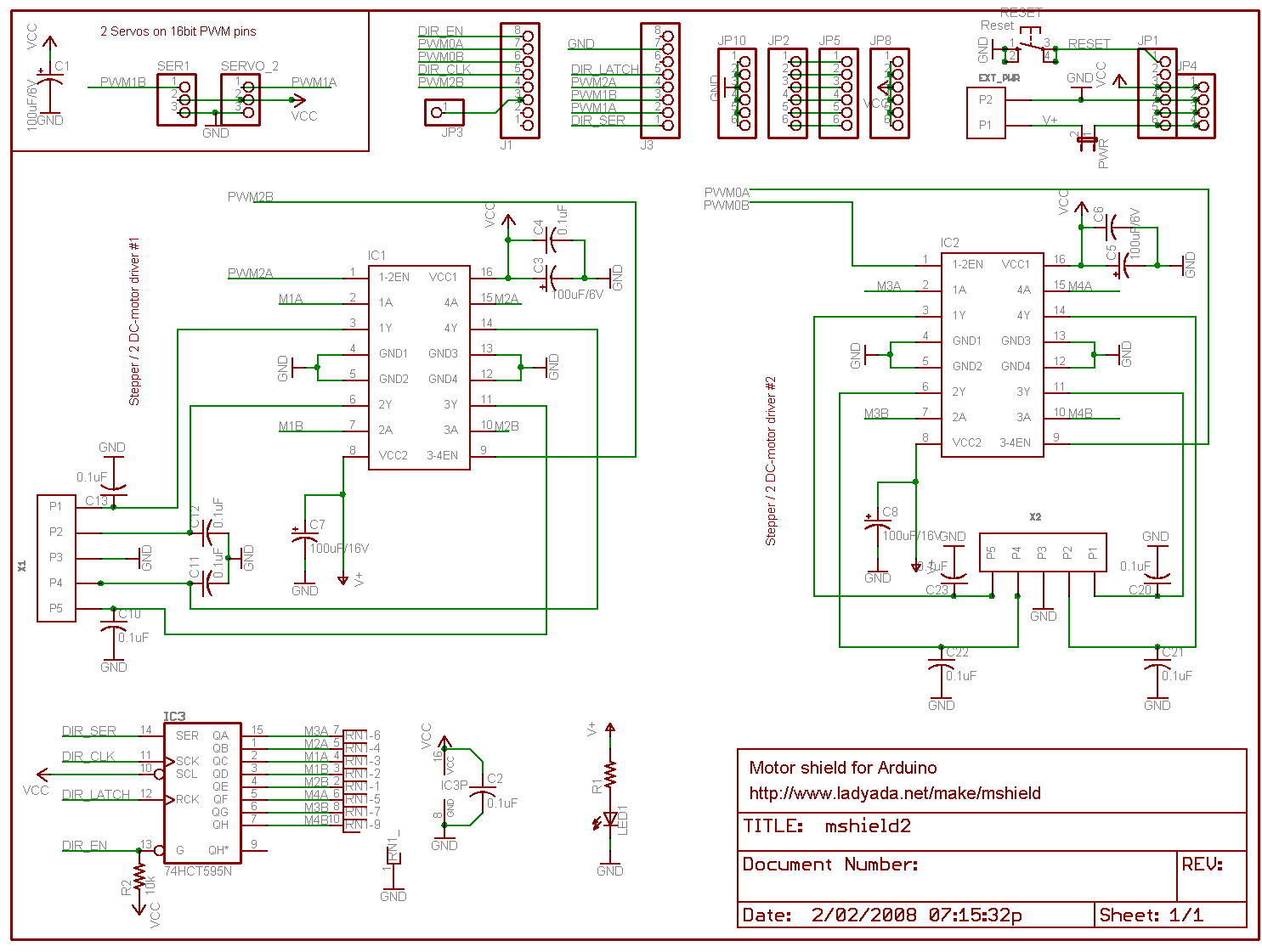
In the end I chose to use the schematics and information from the guys at pyroelectro.com which uses the L298 H-Bridge integrated circuit. My main reasoning was that, although they used a PIC microcontroller, they correctly controlled the L298 with PWM on it's input rather than it's enabling pin. Either way, the PWM signal is still created...
Here's the schematic. I've added a few extra buttons and LEDs and also added a potentiometer for speed control.
Notes:
- The IC is facing towards the viewer (i.e. so that the text on the IC is visible.)
- It's also recommended to use a heatsink!
- Ensure that you connect the ground(GND) on the L298.. It'll overheat and fry if you don't.
- You must use Ultra Fast Diodes for the flyback diodes. More information here
Right, what do you need to know?... The PWM pins are labelled on your Arduino board. By default they output a PWM signal when you feed an analogWrite(pin_number) to them. This creates a pulse that the H-Bridge will respond to. The frequency of this pulse (wave) will then govern the final output voltage to the tracks.
For direction control you either apply digitalWrite(HIGH) to PWM2 and digitalWrite(LOW) to PWM3 or vice versa for the opposite direction. Applying LOW to both pins will stop the output and HIGH to both will short circuit!
I've added S1 and S2 to control my direction. It starts off going 'forward', but pressing S2 will set the direction to backwards. The code is written to gradually stop and then accelerate in the opposite direction. Pressing S1 will then set the direction forwards again and the reverse will occur.
S3 is the emergency stop button. Resetting the throttle to zero will cancel the emergency stop flag.
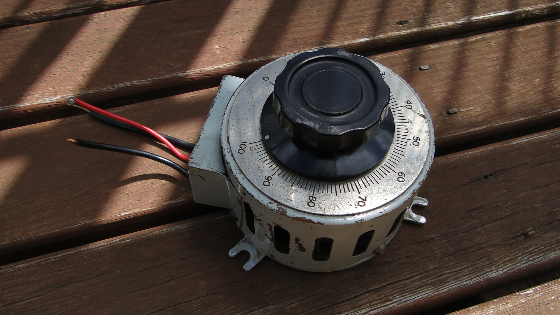
The potentiometer is the throttle... I found a huge one at an antique store down the road and love it. It's rated at 250ohm (no idea what current) and when at '100' the analogRead reports just over 1000. The throttle is only for speed, I really should add a brake lever, as when you return to zero speed the train will only gradually stop. You need to then hit the reverse (or emergency stop) button to stop the train faster.
You'll also require a 12v DC power supply. As your little engines may use up to 1A when starting, make sure this power supply is sufficient. Also, if you don't intend to have the Arduino plugged in to a computer after programming, then this 12v can also supply it (connect all ground wires together!). Just make sure it's a regulated and safe power supply. Note that different Arduinos can handle different voltages! Find your board listed here and then work out the power supply details, otherwise the Arduino Mega details are here (Input max 20v DC).
Source Code
The source code can be downloaded here.
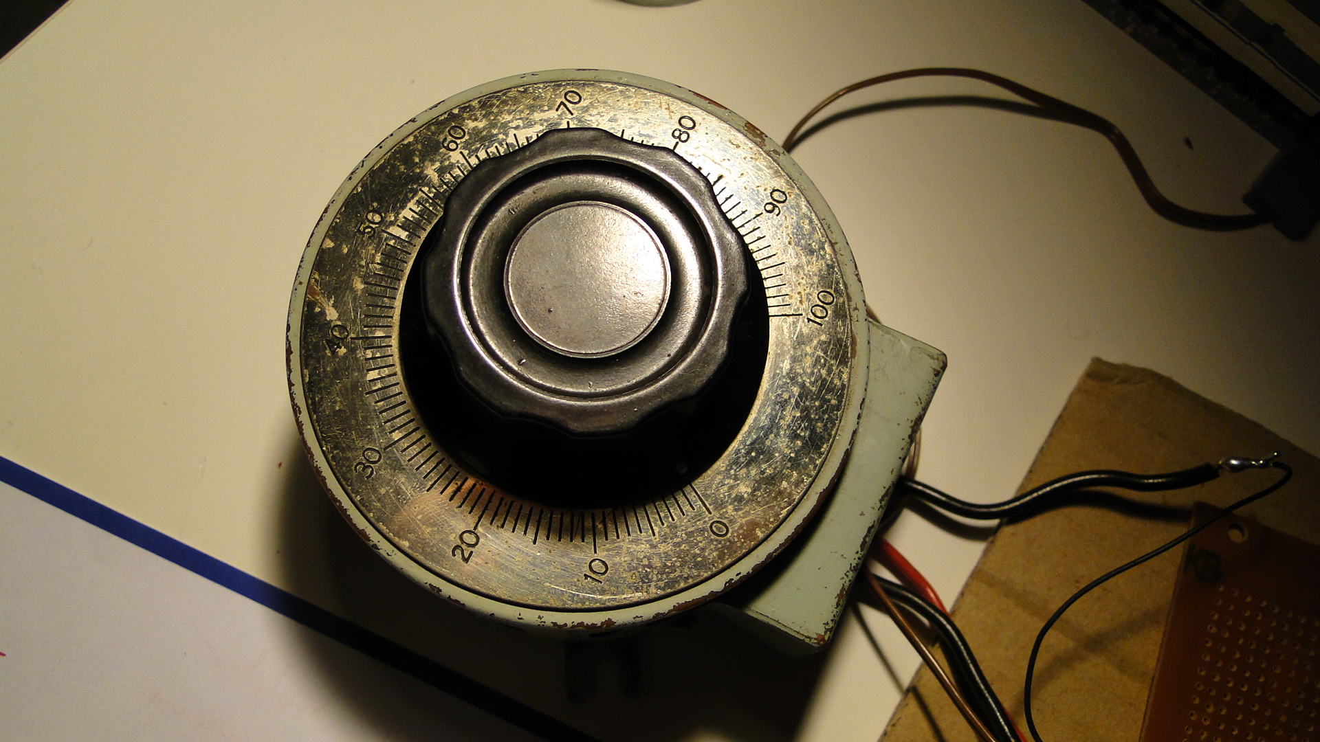
Photos
Here's a few shots of the current set up:
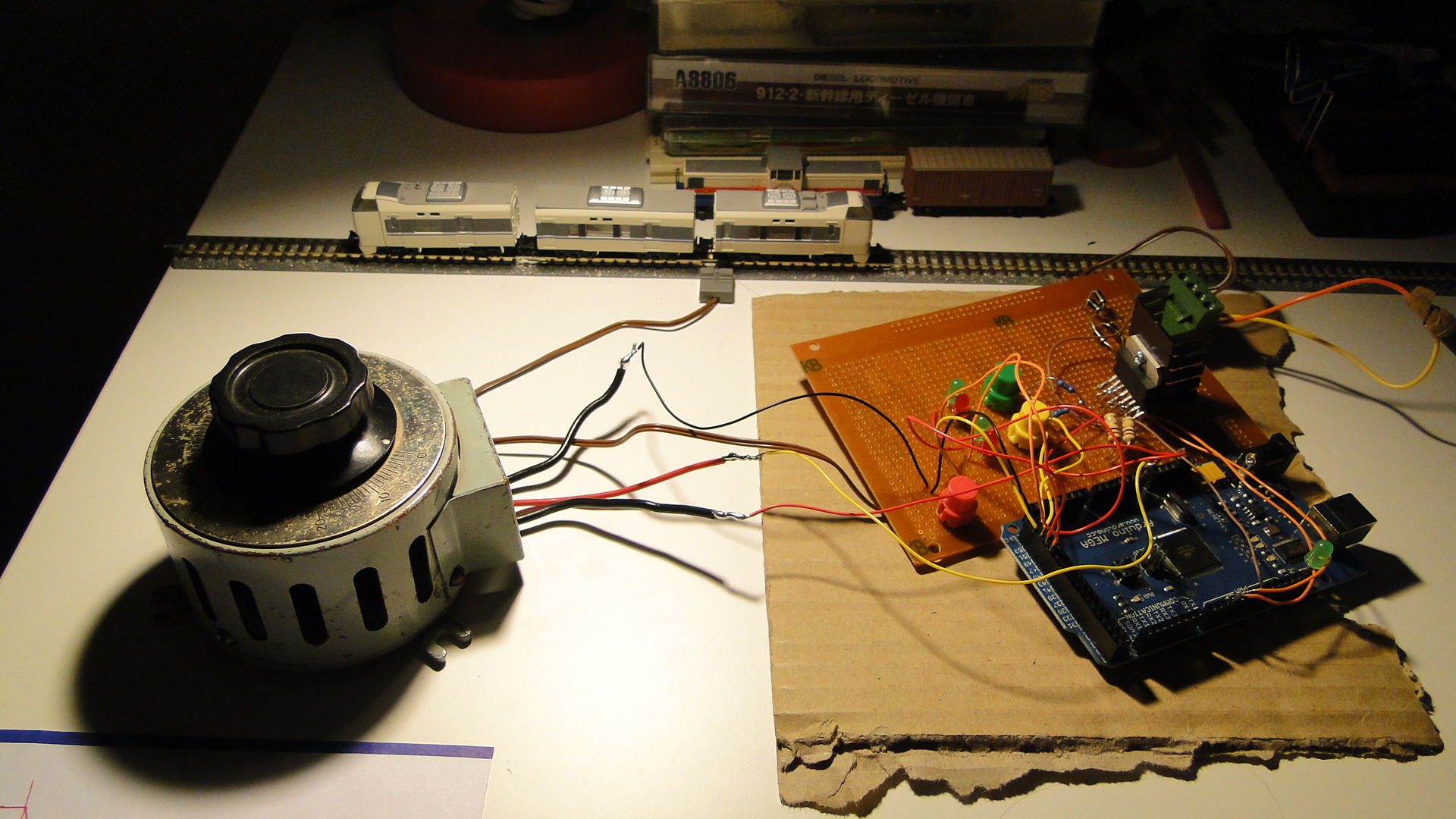
Please do ask any questions you have about this... I've probably skimmed over a lot and am more than happy to update this as necessary. I intend on getting on to more interesting things with this controller as I get the time.
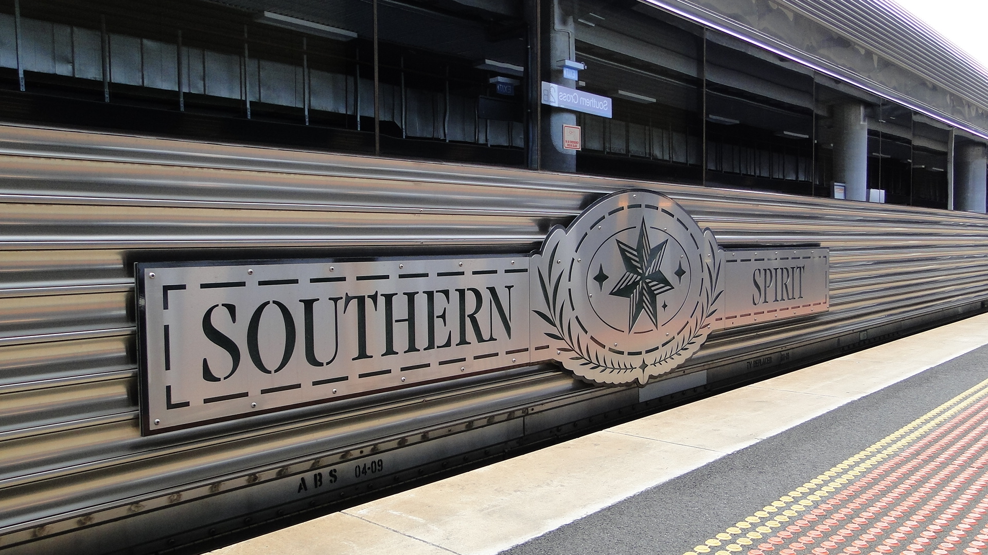
Melbourne – The Southern Spirit
Great Southern Railways (or GSR) is a long distance train operator in Australia operating famous trains such as The Ghan, The Overland and The Indian Pacific. In 2008 they announced that they were going to run a service that brought all of their current services together, including a trip to Brisbane, to be known as the Southern Spirit. Unfortunately, due to the 'Global Financial Crisis', this service did not run in 2009... being postponed for a year.
So, after returning from Japan, I noticed a thread on Railpage titled 'Loco hauled passenger services...' and realised they were talking about the Southern Spirit. This brought back all the feelings of anger from last year when I'd heard it was to be completely cancelled... I was excited back then since the train was to make an overnight stay in Canberra! It also made me realise how much people had forgotten (or ignored) the service altogether, as it seemed like a pipe dream.
Anyway, the service was now running, and was to make a stopover in Melbourne on a weekend... perfect timing. It turns out Saturday was to be great weather, so I chose the beach instead, but the train was to depart for Sydney on Sunday the 17th December and I was going to capture it.
Just a note, the full album of photos and videos is located here.
Departing Melbourne
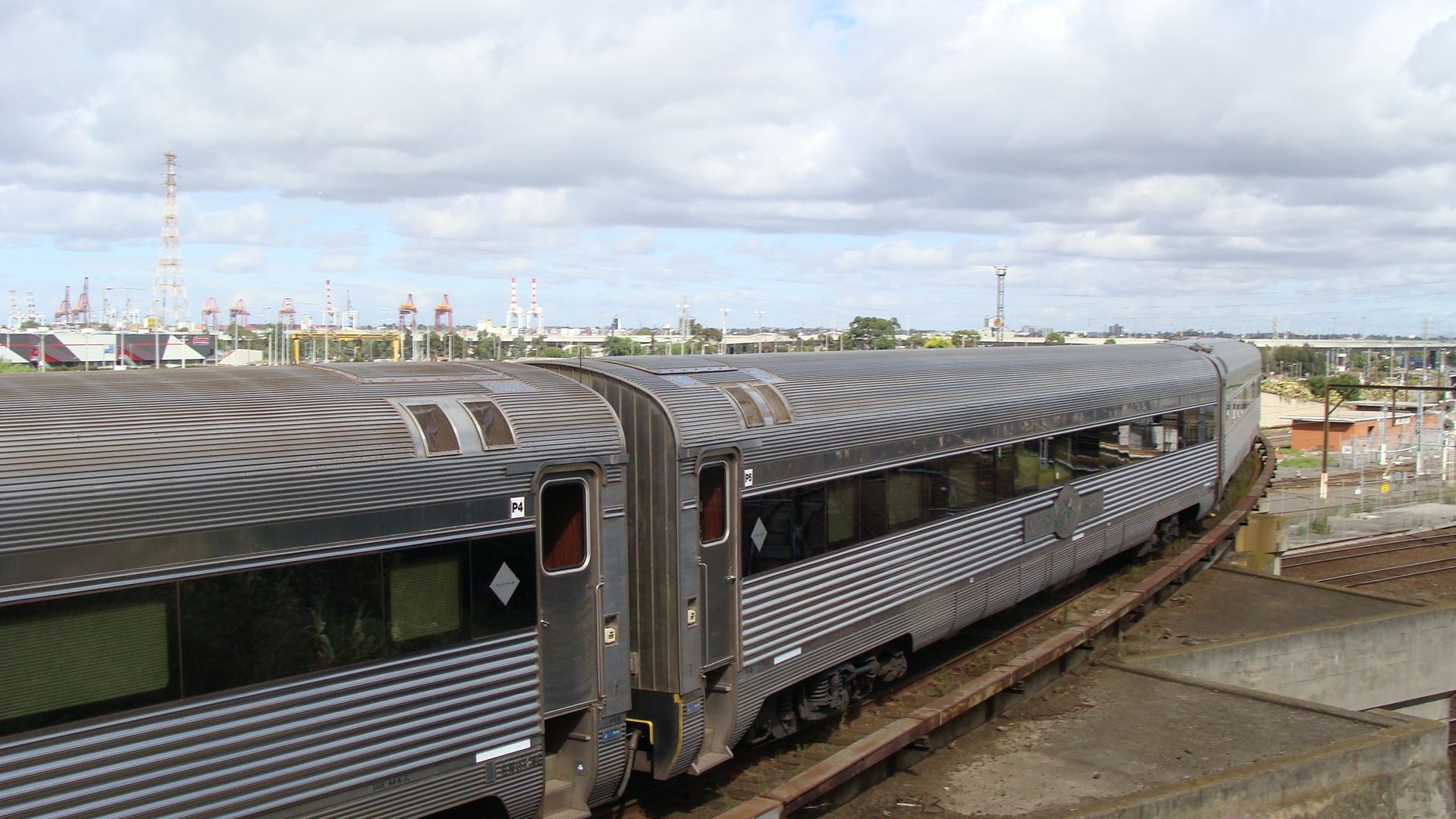
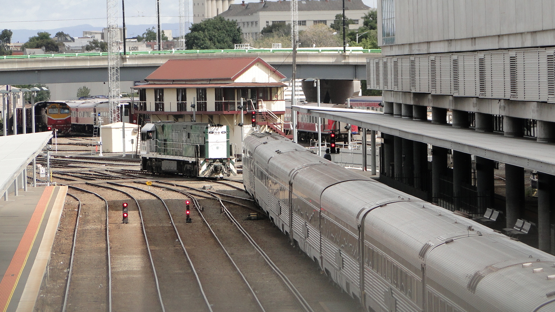
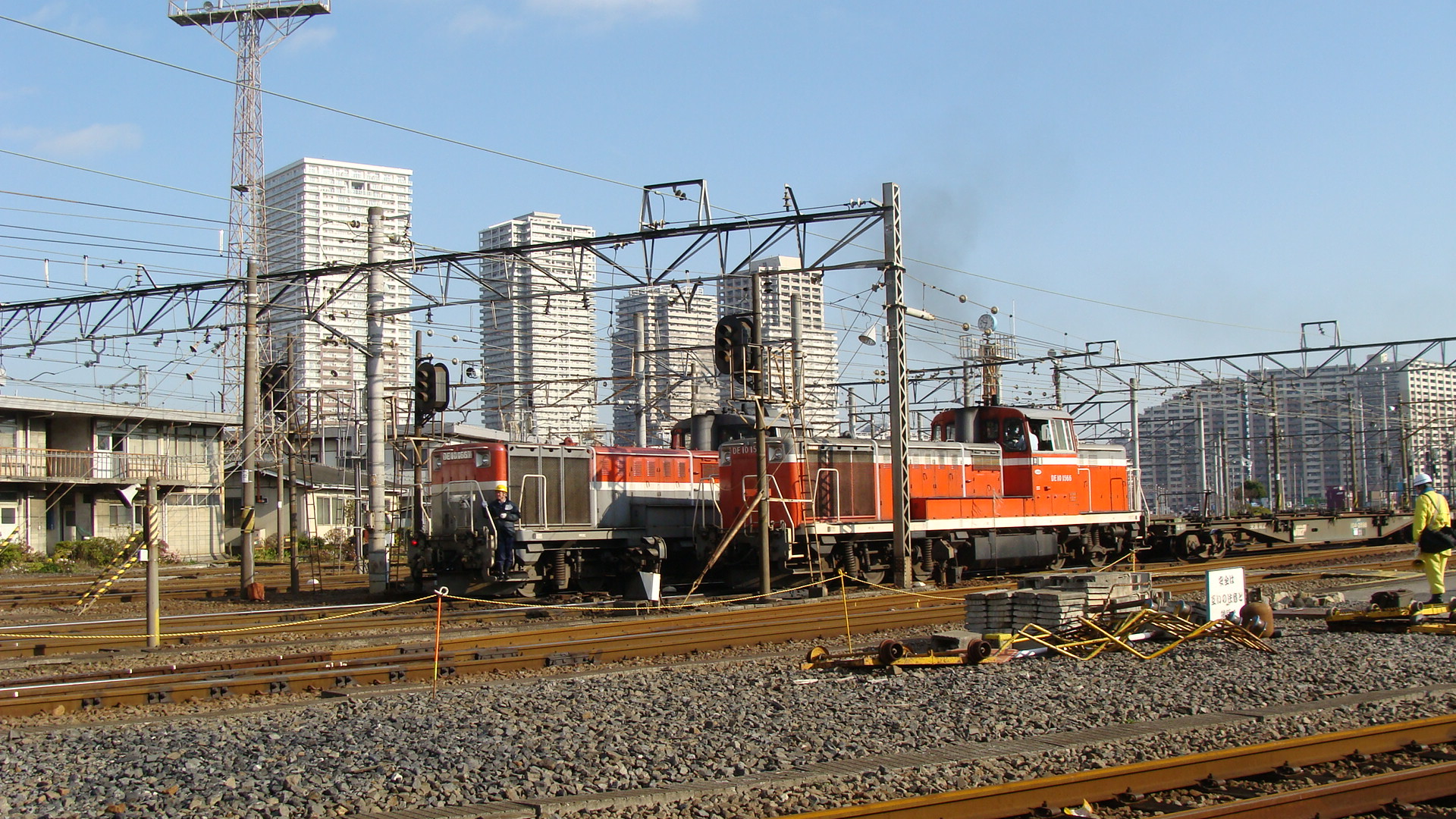
The consist and loco had spent the night in Dynon Yard which is a large area of freight and maintenance operations in Melbourne. I jumped on my bike on Saturday evening and could see the consist from Mooney Ponds, but couldn't get a good shot of it. I did at least confirm that the train existed and could also determine it's approach to Southern Cross Station the next morning.
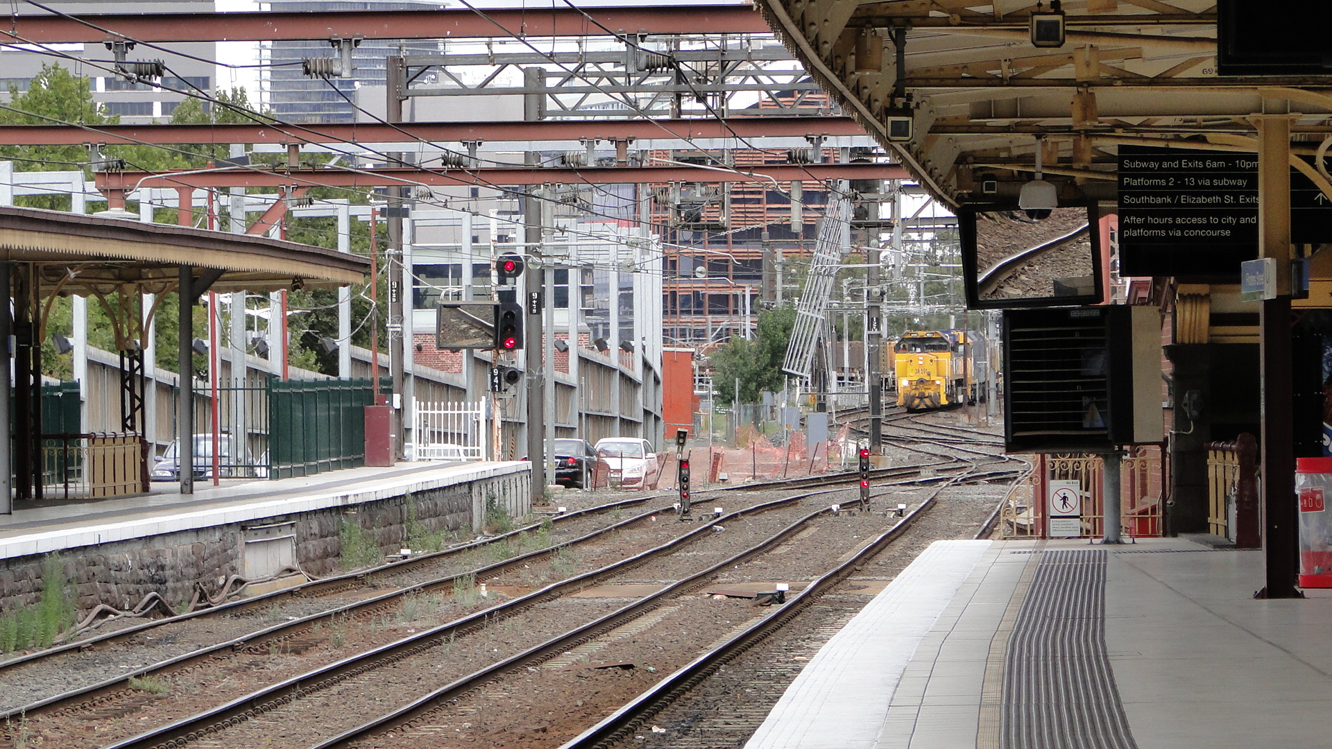
I made it to North Melbourne Station at 9am on Sunday morning and then proceeded towards Southern Cross following the railway. Most of the lines running are broad gauge, but there is a single standard gauge flyover from the yards to the Southern Cross a little further south of North Melbourne station. Here I waited for the service to move in.
Whilst waiting I saw a few things I didn't expect. It turns out that the second line on the flyover is broad gauge and is used quite a lot!
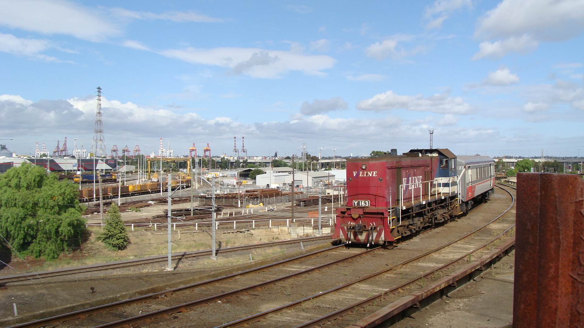
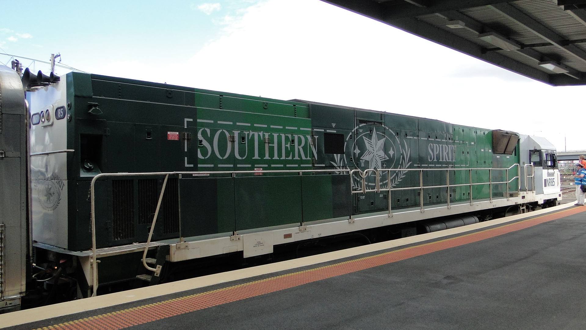
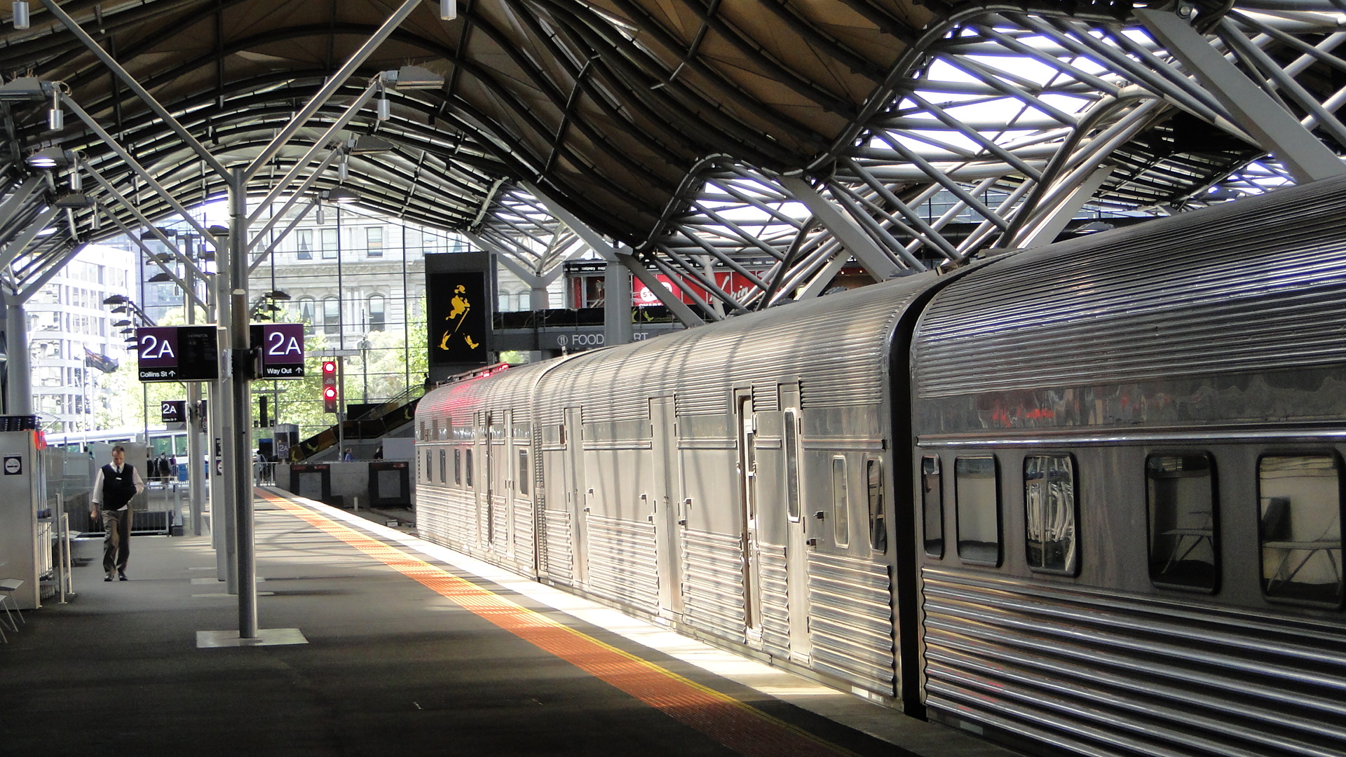
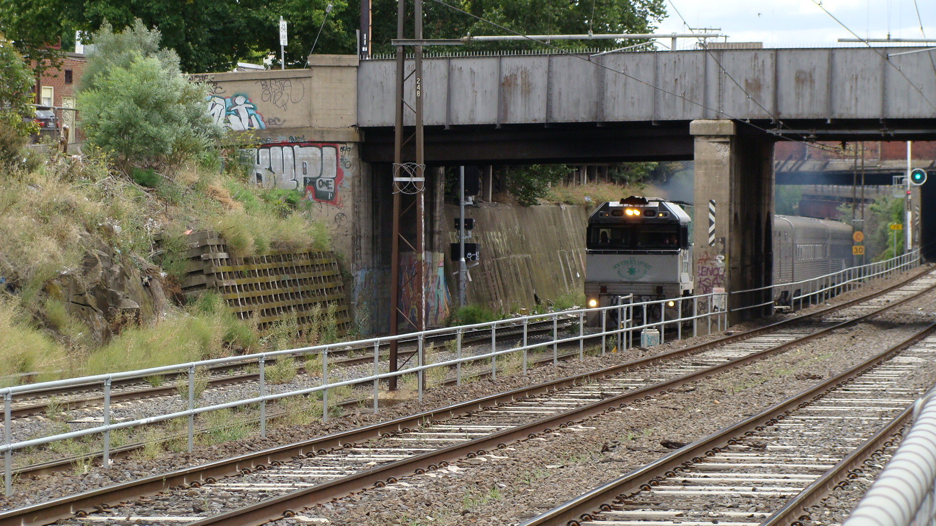
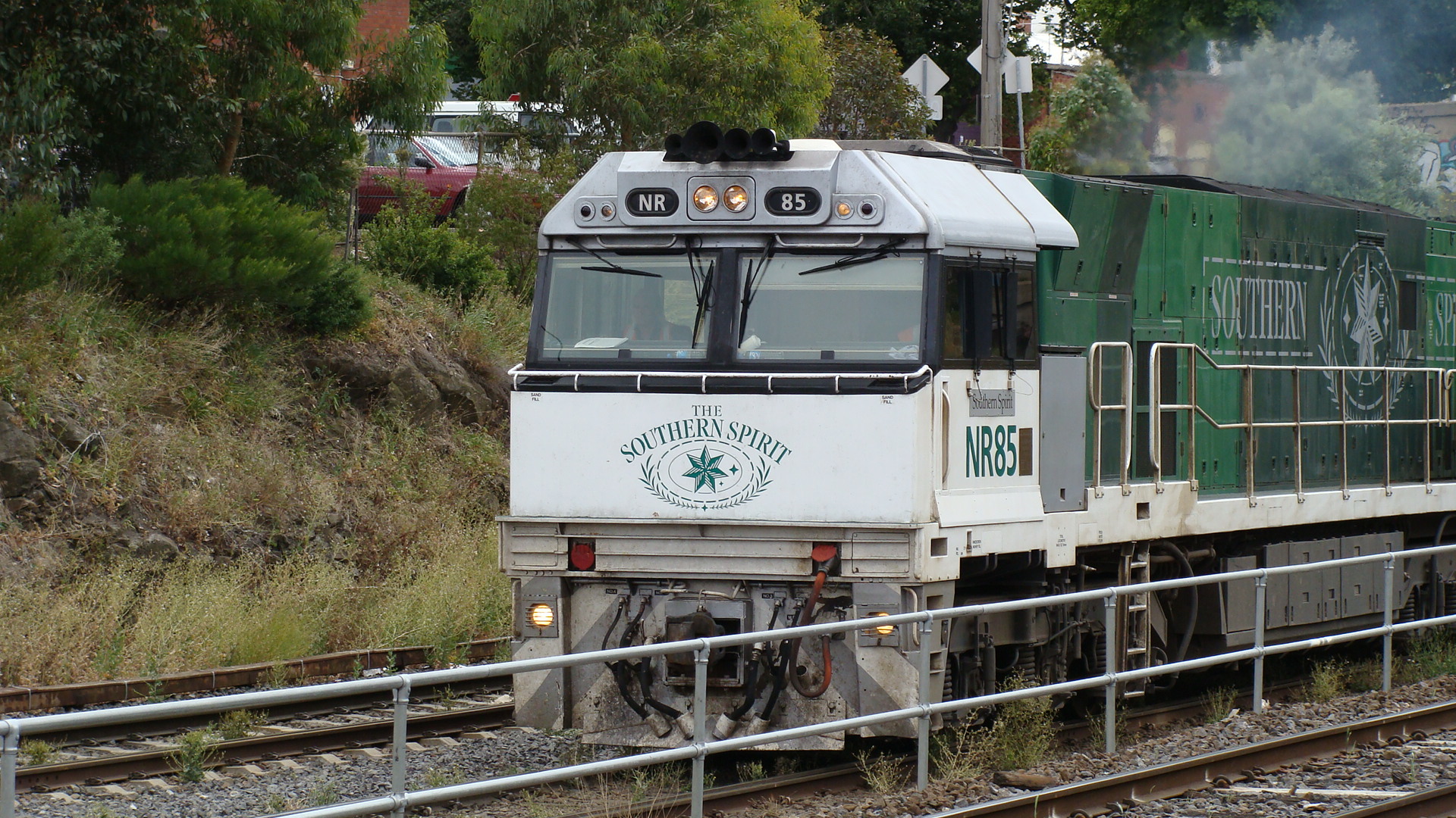
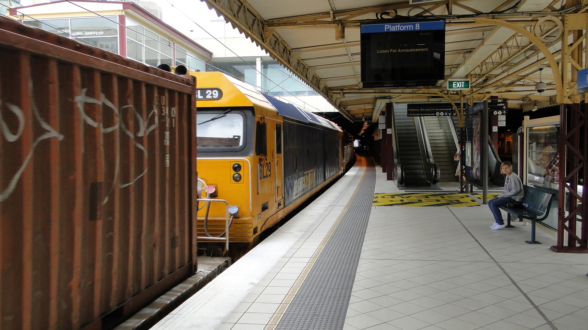
At around 1010 NR85 could be seen long-end-leading (which is extremely unusual for an NR) towards the flyover from Dynon Yard. It proceeded slowly over the gradient and then down towards Southern Cross.
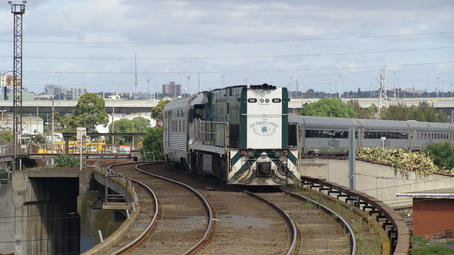
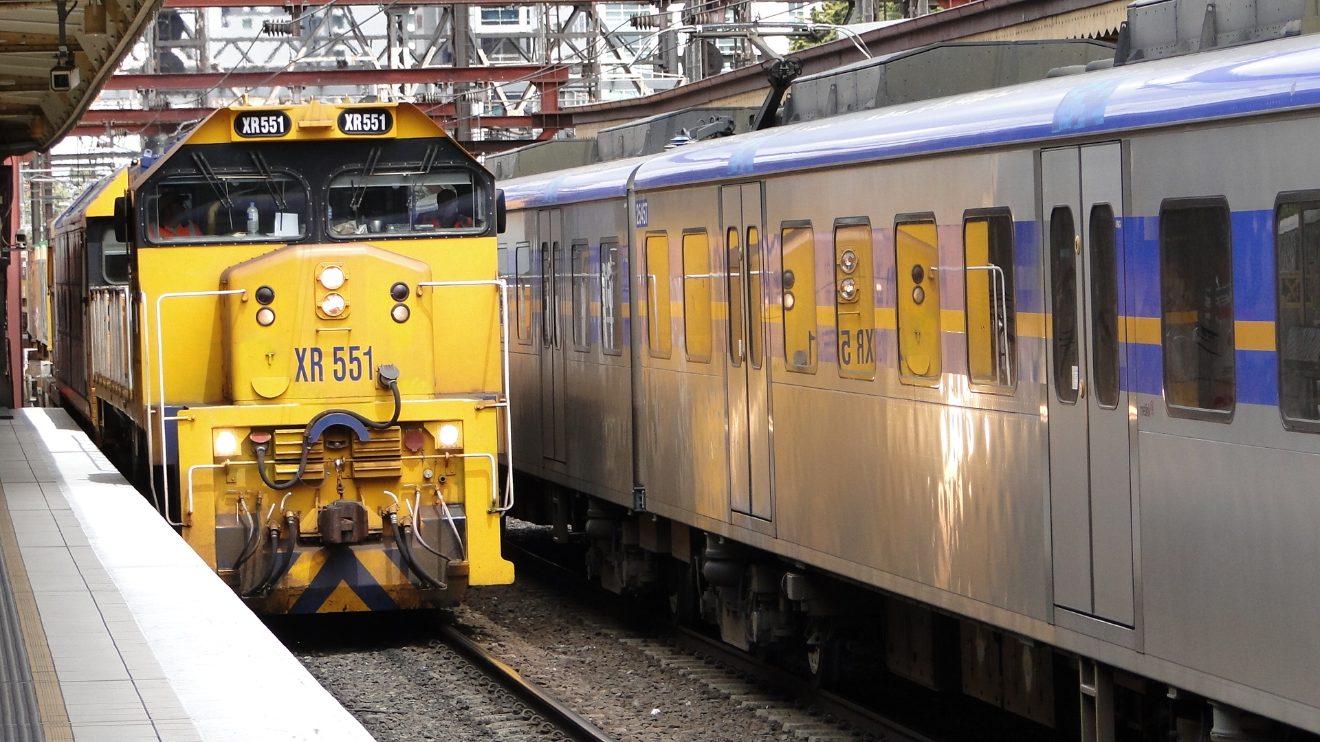
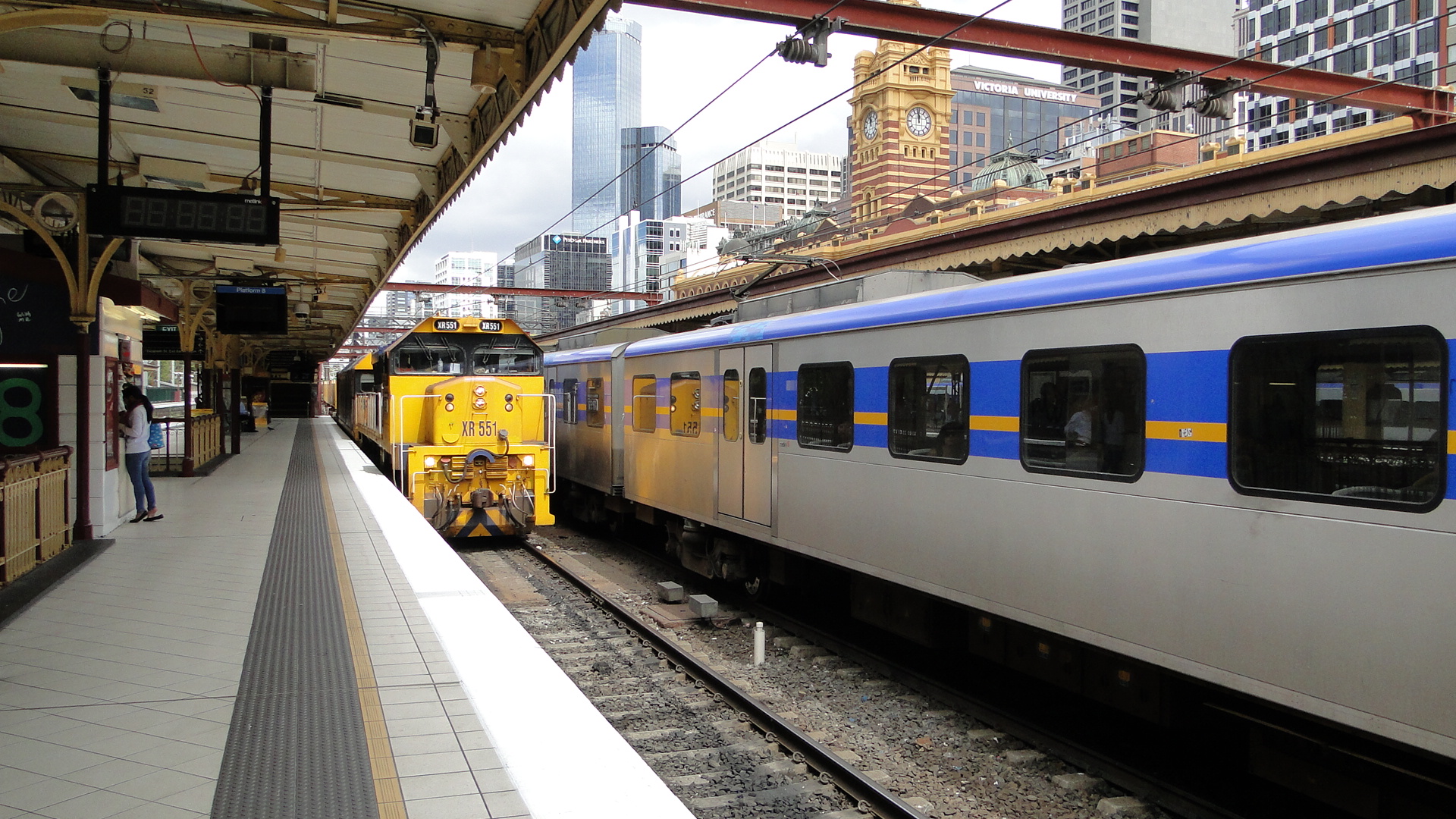
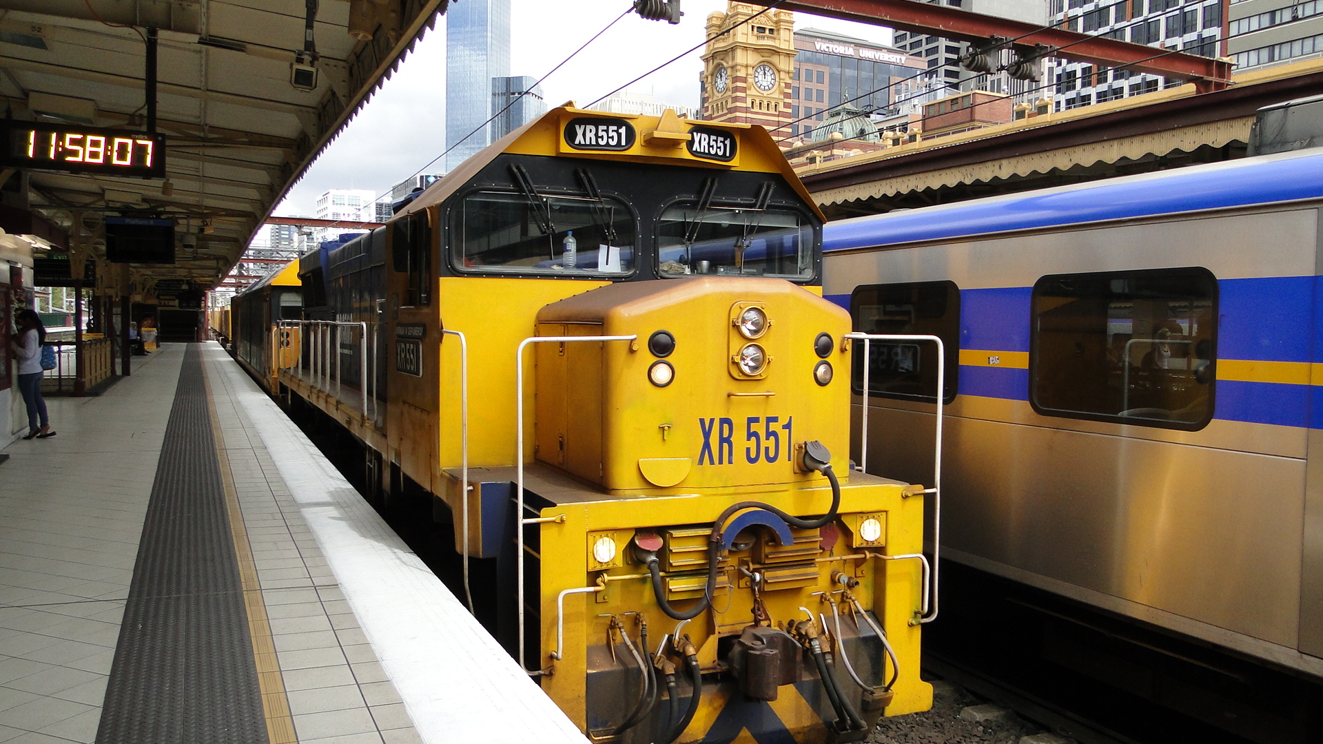
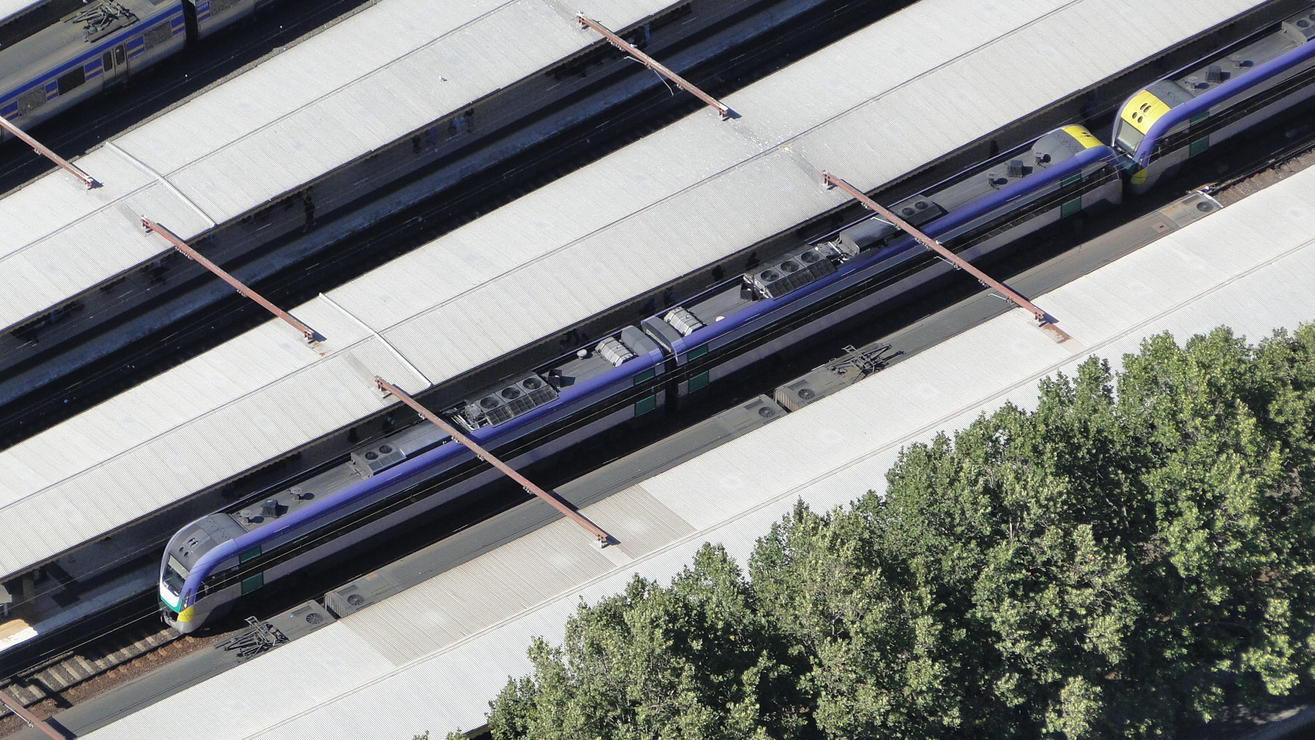
From here, as I was on foot, caught a suburban to Southern Cross and took a few more pics of the train.
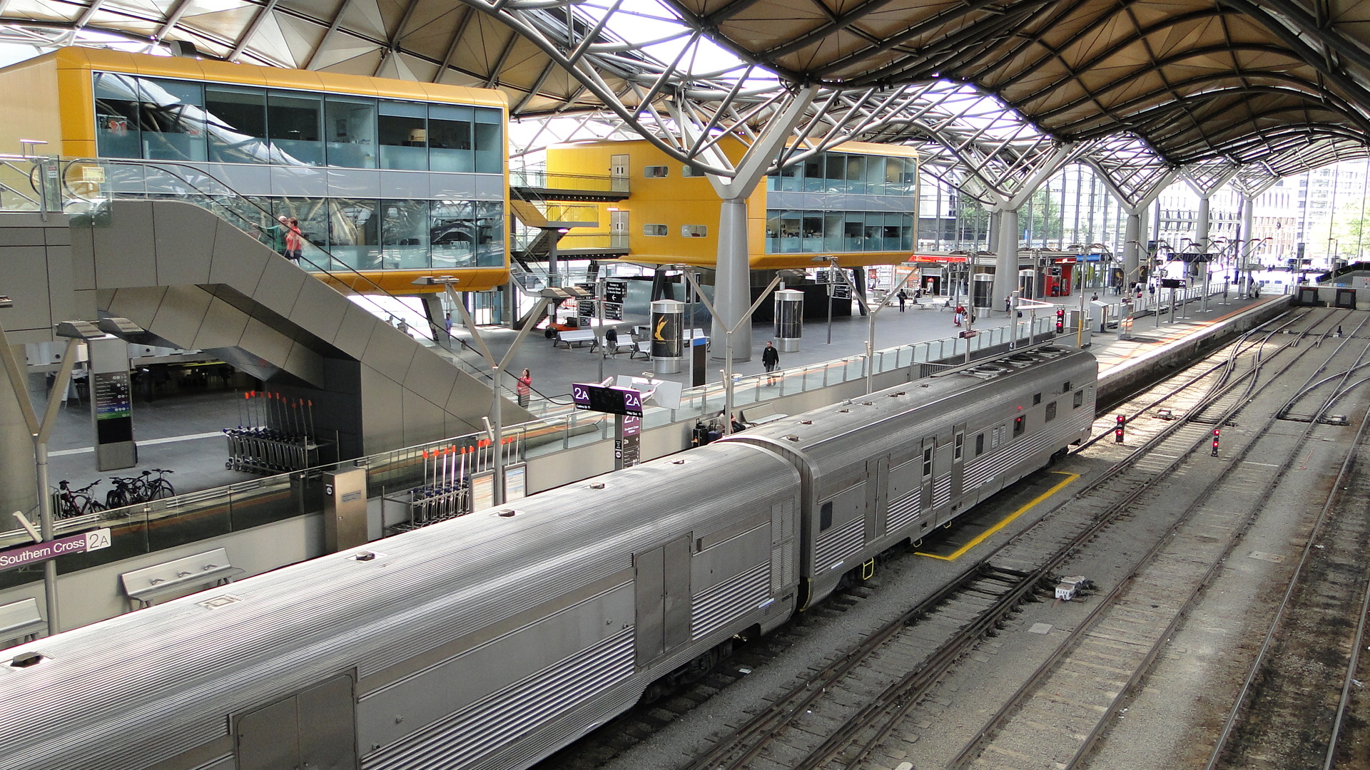
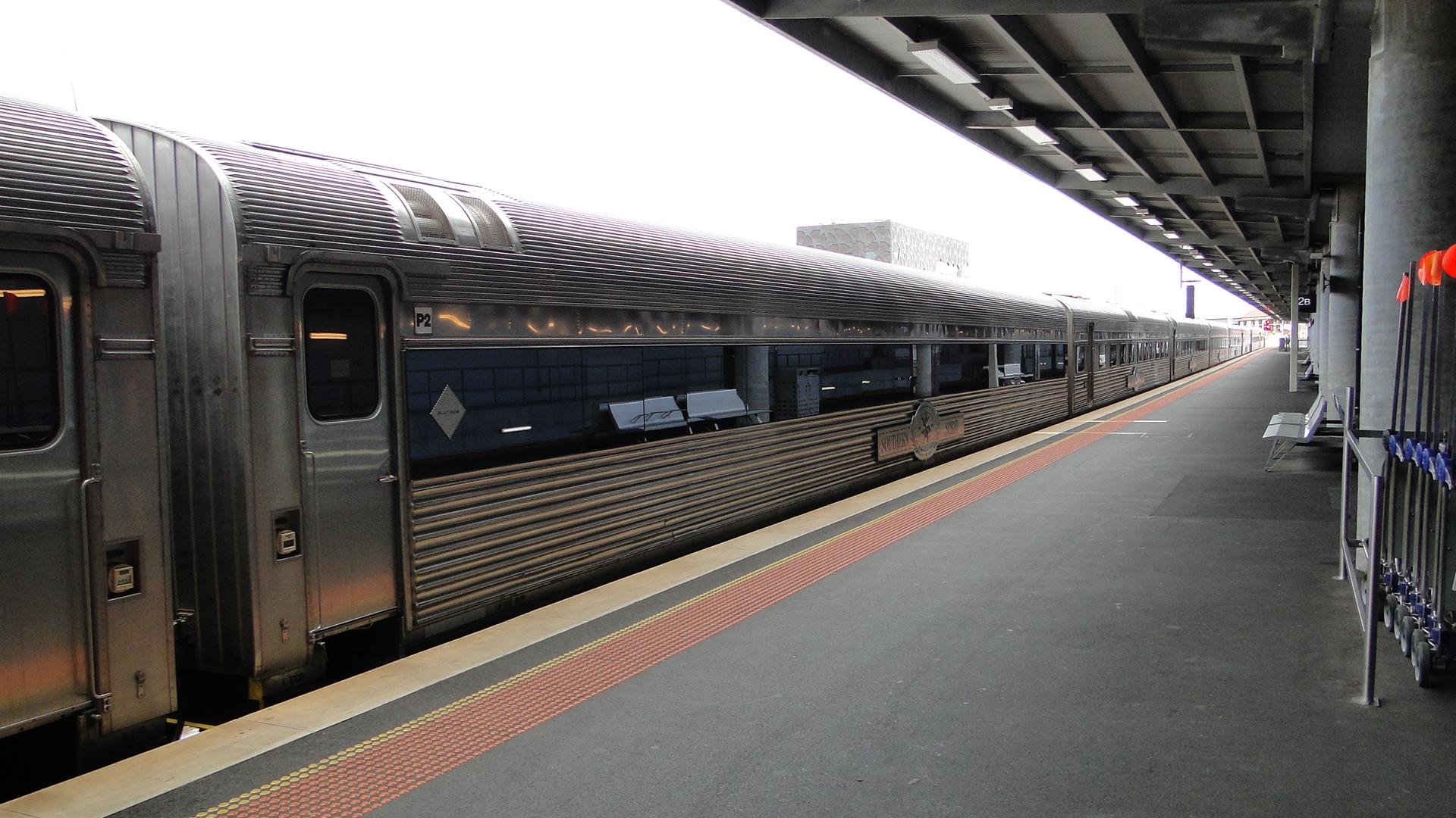
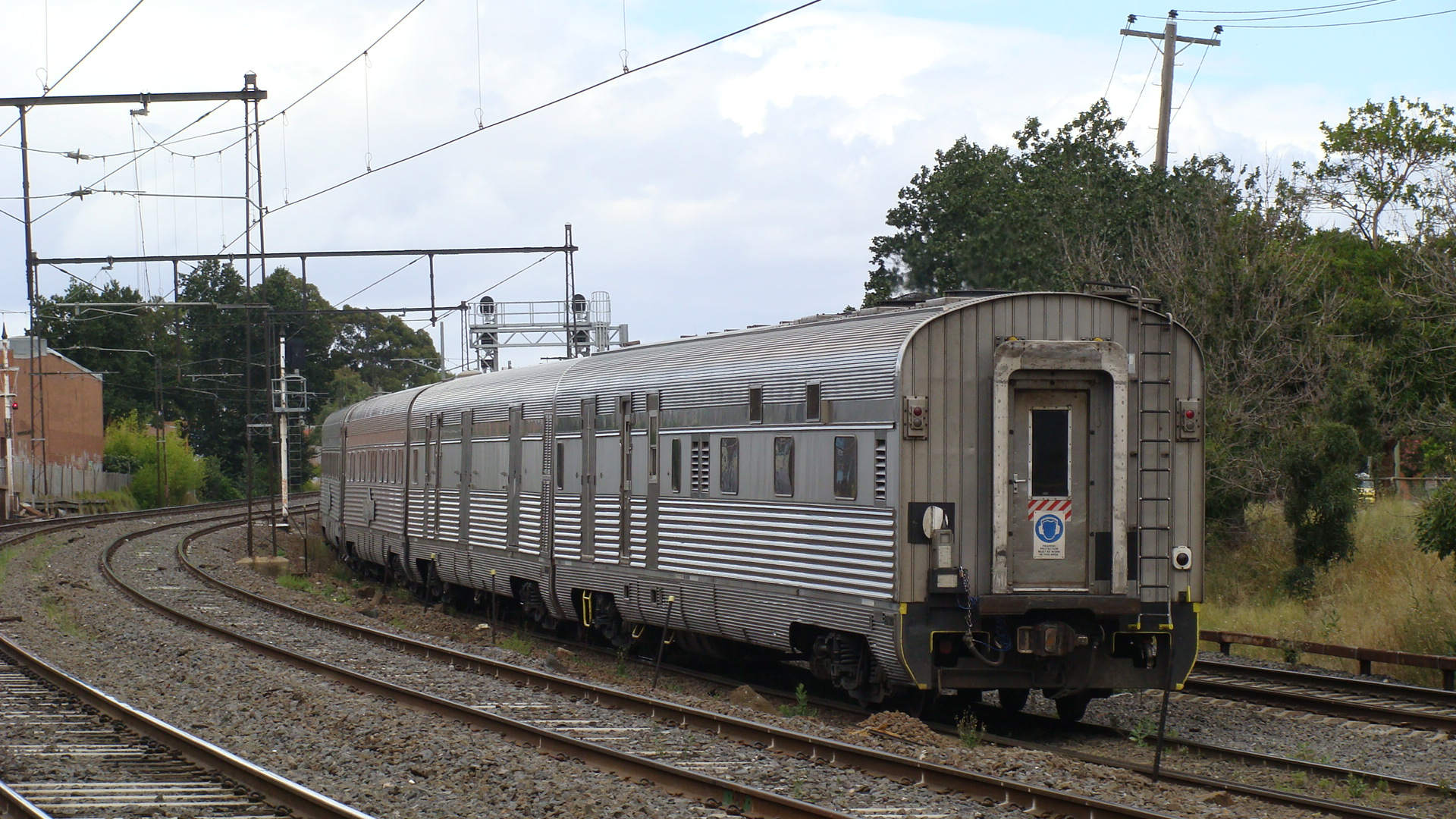
I then jumped on the next Footscray-bound service and found a spot trackside halfway between Footscray and Middle Footscray. Of course, there just had to be a passing EMU as I was recording a video of the Spirit leaving Melbourne.
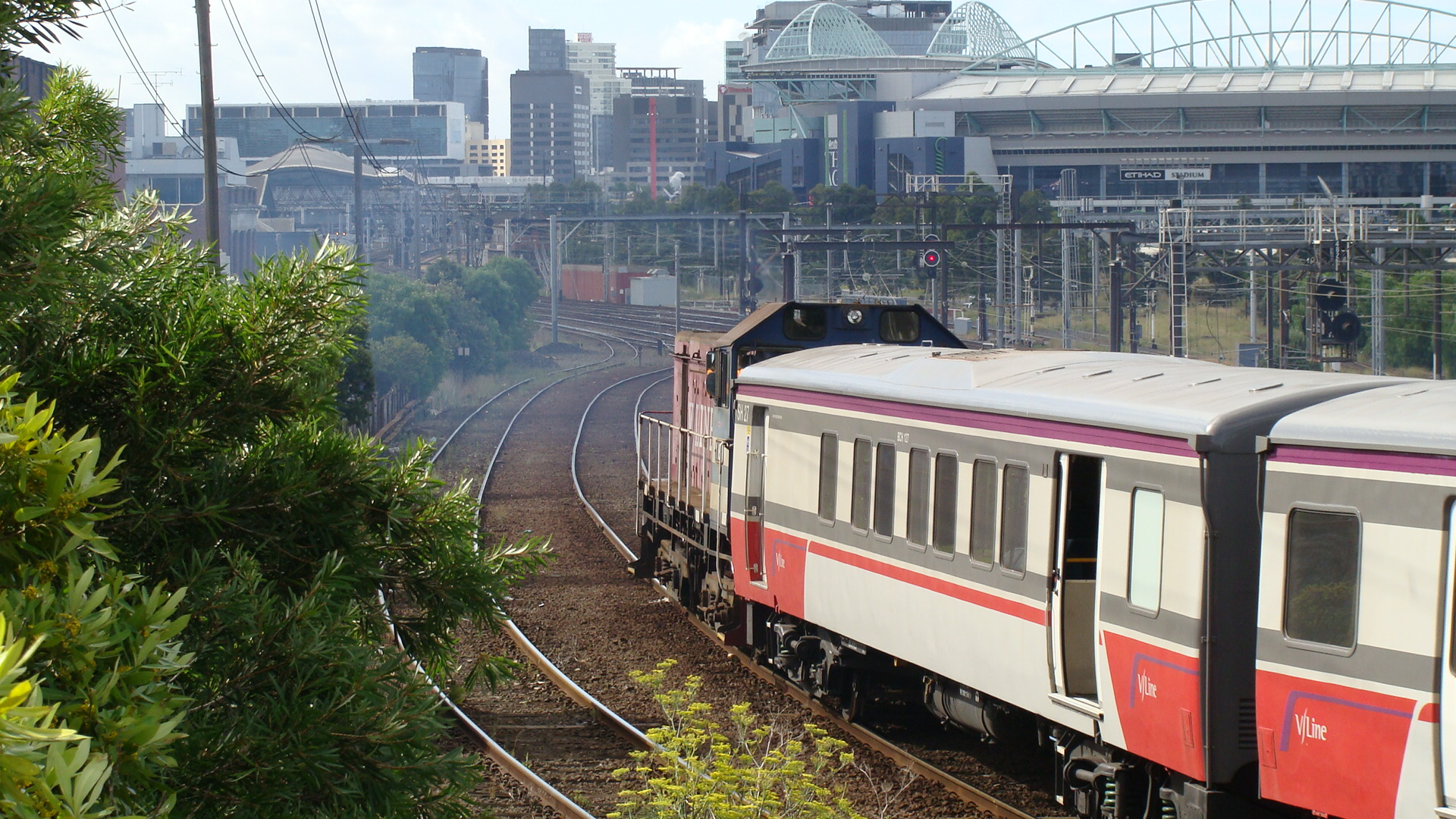
Whilst returning to Flinders Street, I saw a freight service heading south towards Southern Cross Station. The EMU I was on managed to beat it to Flinders Street and I got a few shots of it passing through the station.
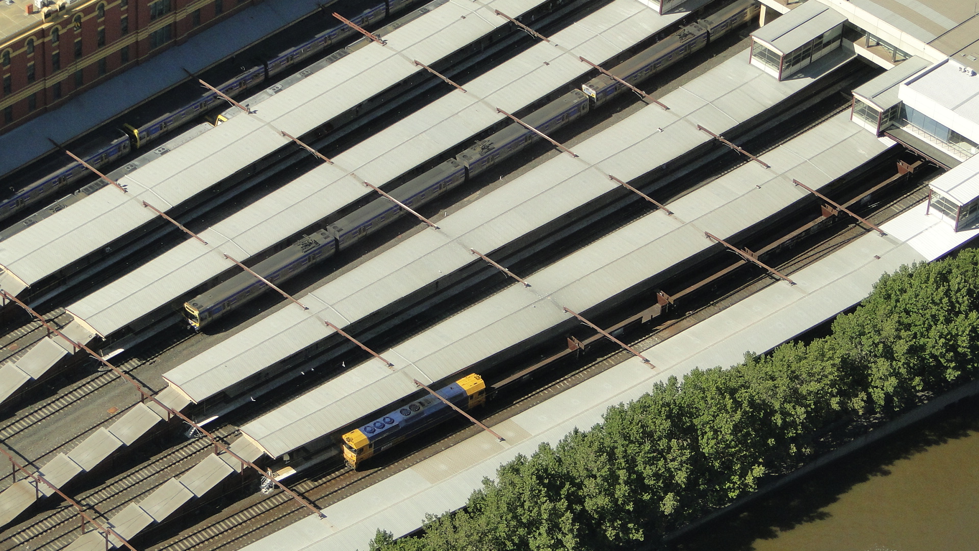
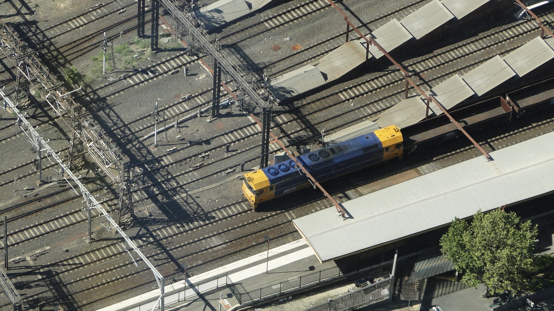
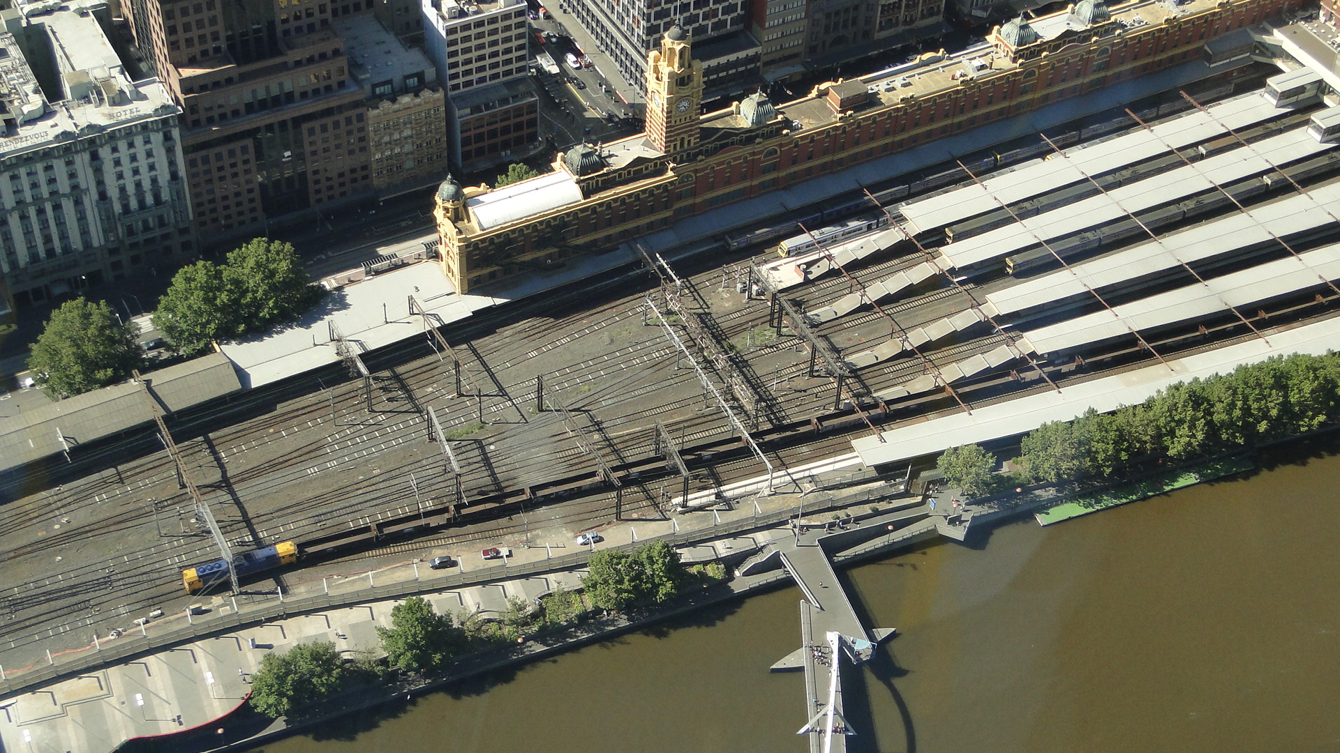
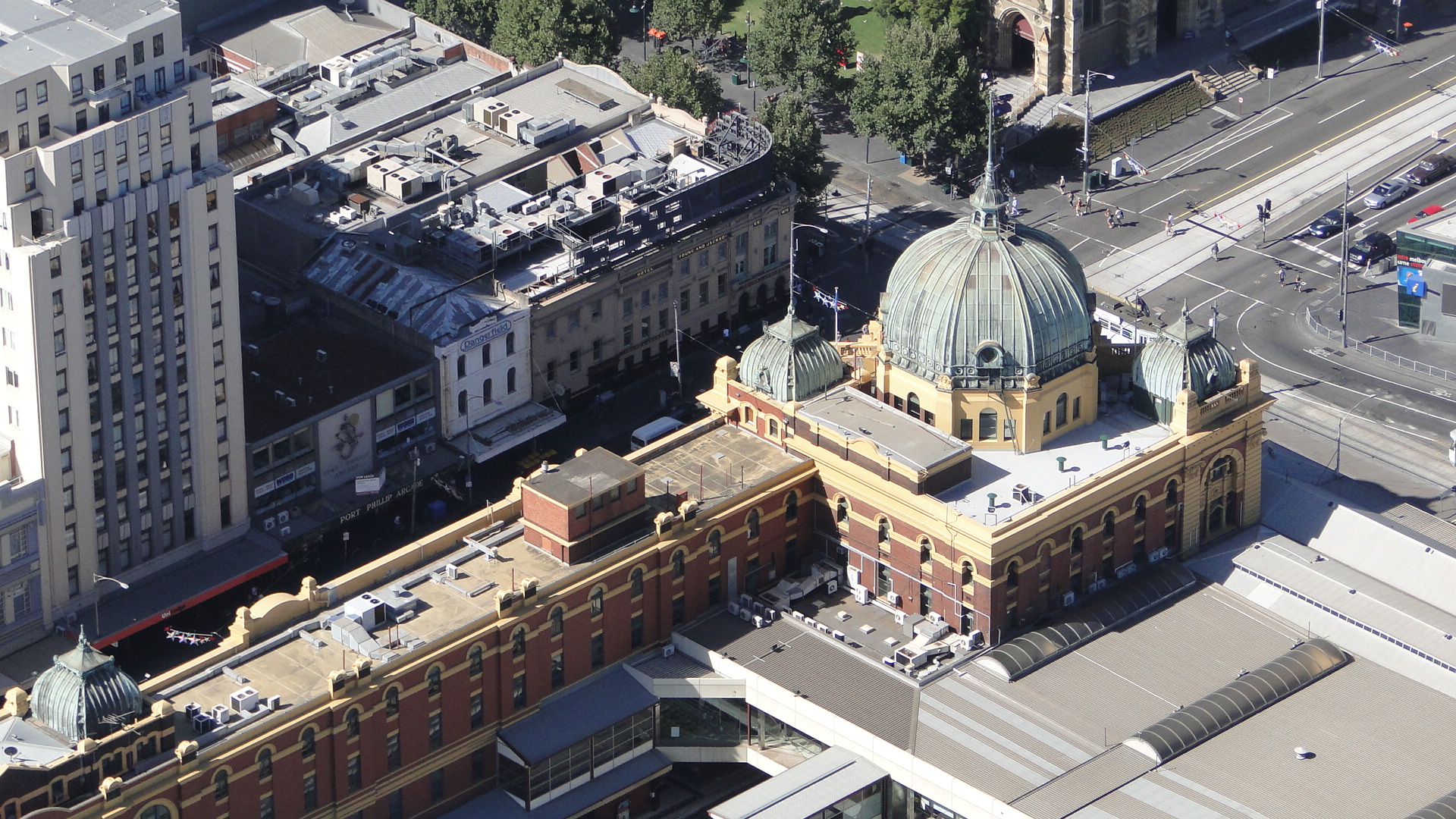
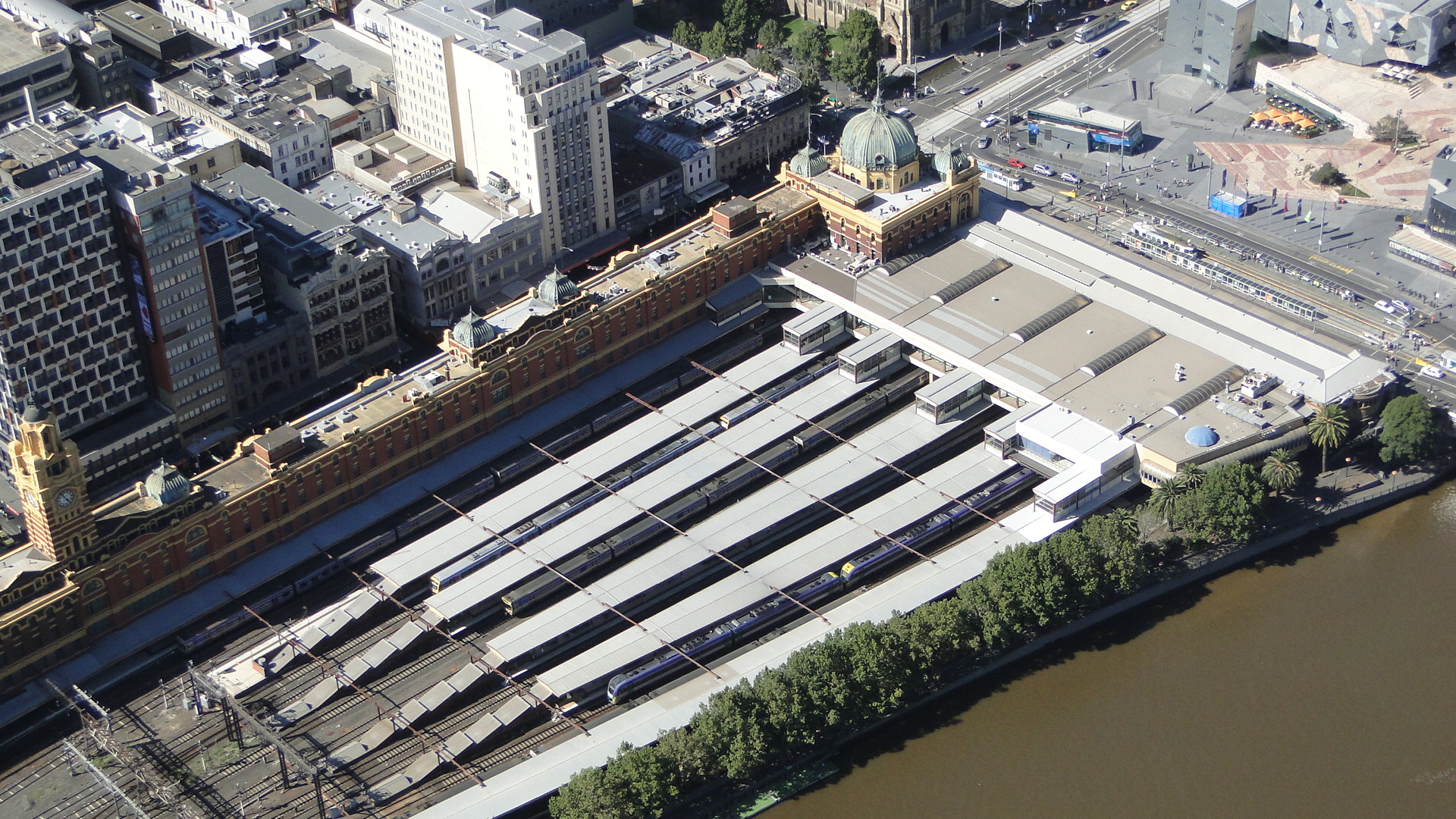
Shots from Eureka Tower
Unrelated, I've also been up Eureka Tower lately and got a few shots of the return freight service.
Osaka (incl. the M250 Super Rail Cargo)
Due to having a lot of friends in the Kansai area, I'm always found basing my holidays in Japan from Osaka. Sure, the trains have less colour and there are no where near as many networks as Tokyo, but there's something about the city, it's warmth and, of course, the people. Did I mention trains? Also the trains.
I'm usually found loitering around Shin Osaka station (both photographing and residing) as it's the only place to get on the Shinkansen and also has a lot of limited express services stopping through. I usually stay in the same place; a room rented out by a Japanese citizen for a very good deal, but this time his apartment was booked. I instead ended up near Noda Station (on the JR Osaka Loop Line) and had to, more or less, start my learning of the timetables and networks from scratch. Of course, due to JRs punctuality and level of service, I really had no issues getting around... It just meant getting up 30 minutes earlier if I wanted to jump on a Bullet train.
One good bit about the Loop Line is that it's not all just boring local trains. It so happens that I was in the 4th quarter of the line (counting clock-wise from Osaka Station) and therefore only 2 stations from Osaka itself. This was really convenient, but also meant that I was on the Limited Express line (that bypasses Osaka and goes direct from Shin Osaka to Fukushima) that is also used for freight!
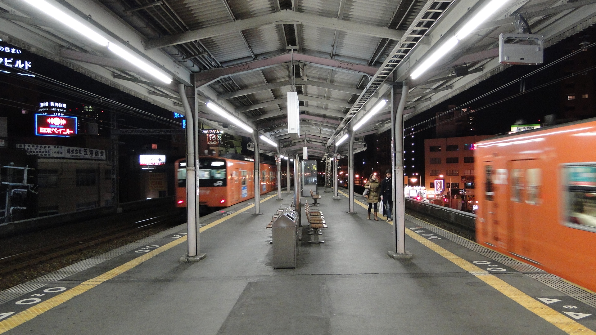
Of course, it wasn't until my last day that I actually saw freight on the line, as you either have to fluke it and see standard container trains to the port out near Universal Studios Japan or wait until around 11pm to see the M250 Super Rail Cargo leave. Since I'd found out the timetables of the M250 prior to this trip, I'd known what to do this time (instead of just seeing it shoot by when stumbling home from karaoke) and got in position to get a photo of the damn thing.
M250 Super Rail Cargo
My first attempt to see this train was on a weeknight from Noda Station at 10pm, heading to Ajikawaguchi Station (which is right next to the yards where the M250 is loaded.) Upon arriving, I saw the M250 cab lit, but also noticed that the Sagawa Transport trucks were still speeding into the yard in quick progression. I watched (walking from Ajikawaguchi Station up to USJ Station) as the trucks drove in, lined themselves up in a queue and then were unloaded by forklifts. They all knew exactly which car number (flat wagon in the consist) to drive up next to. The forklift would then pick up the container, the truck would drive off and the forklift would place the container on the train.
I soon realised, as I walked along the yard towards USJ, that there were only about 3 or 4 more containers left to load... and those trucks were already in the queue waiting to be unloaded! Hence I started speeding up my return, on foot, to Ajikawaguchi, as this is where the M250 would join the Yumesaki line (the line from the Loop Line to USJ/Sakurajima), as this would provide a good vantage point for a photo. Turns out I couldn't get a clear or steady shot without a tripod, so a movie was to be it.
All of a sudden this random music started playing (turn the volume up on the movie, you can hear it at the start) over ALL speakers in the yard... I thought the Thunderbirds were about to arrive. Then I heard a very feeble train horn and, before I knew it, the M250 was departing. It was 2304 and I looked at the timetables on the platforms at Ajikawaguchi... there were to be no trains for the next 4 minutes, a perfect time for this high-speed freight service to depart. And it did! It accelerated quite quickly, passed onto the left line and then disappeared out of sight.
Of course, I then wanted to get this train at another station along the line. I tried again the following Sunday and but I only got to see the consist shut down in the yard and partially loaded. As I arrived at Ajikawaguchi Station, the lights in the yard started shutting down row by row (around 2250) and I could tell that an employee was walking along the yard, manually switching them off. Fail for this night to get a movie.
I then ran out of time in Osaka to get another shot. The train departs at a bad time, as its always when you've had your fill of shabu-shabu, you've sung a few songs at karaoke and you're just not ready to leave the booth! Of course, the last loop line train is also sometime just after midnight, meaning a run to get a video of a train is usually always out of the question. The only real vantage points are at Nishikujo, Noda and Fukushima Stations which are out of the way from where the nightlife is.
Hence I only have the above video... but I'm glad I saw the train, finally... functional.
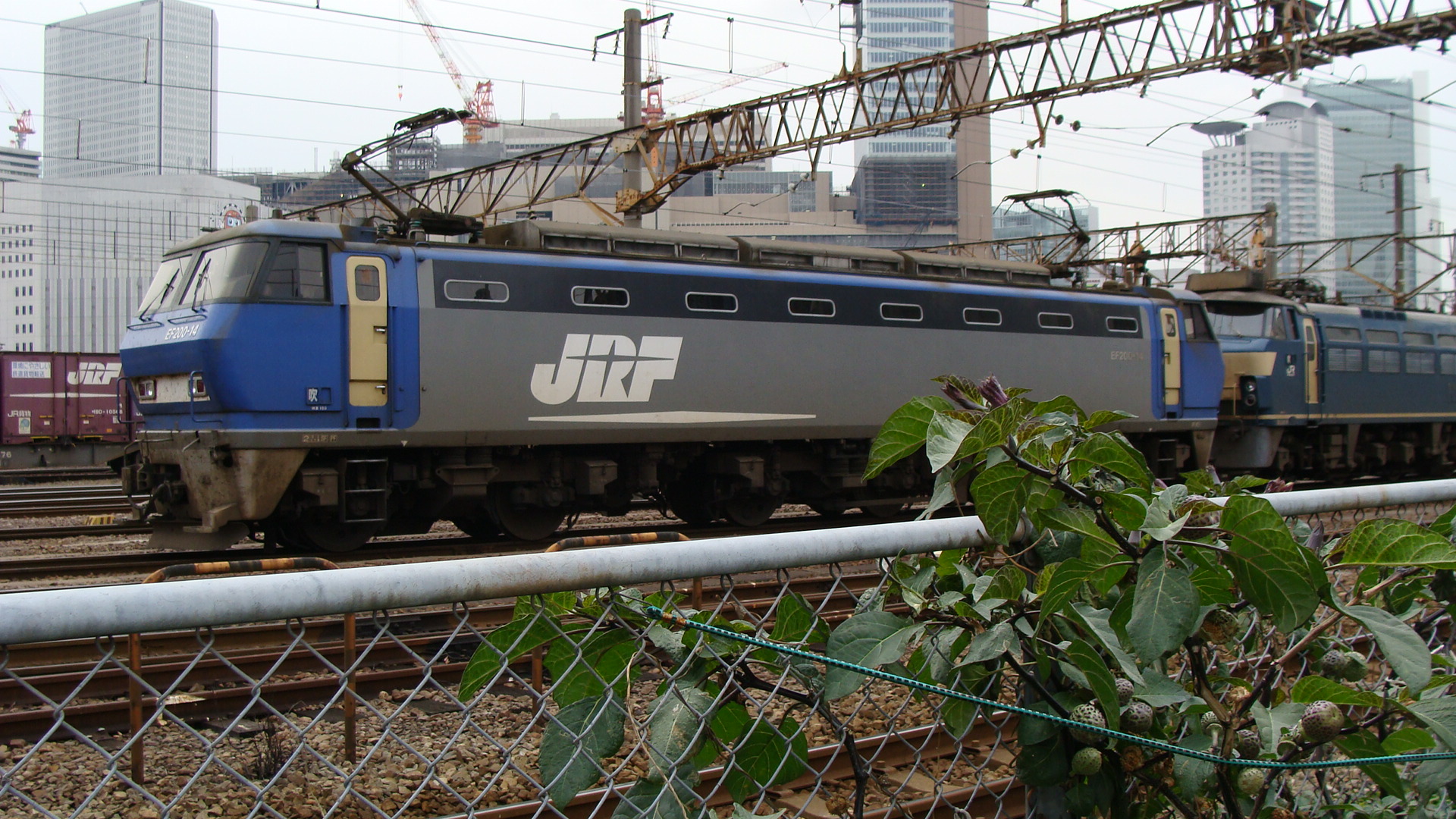
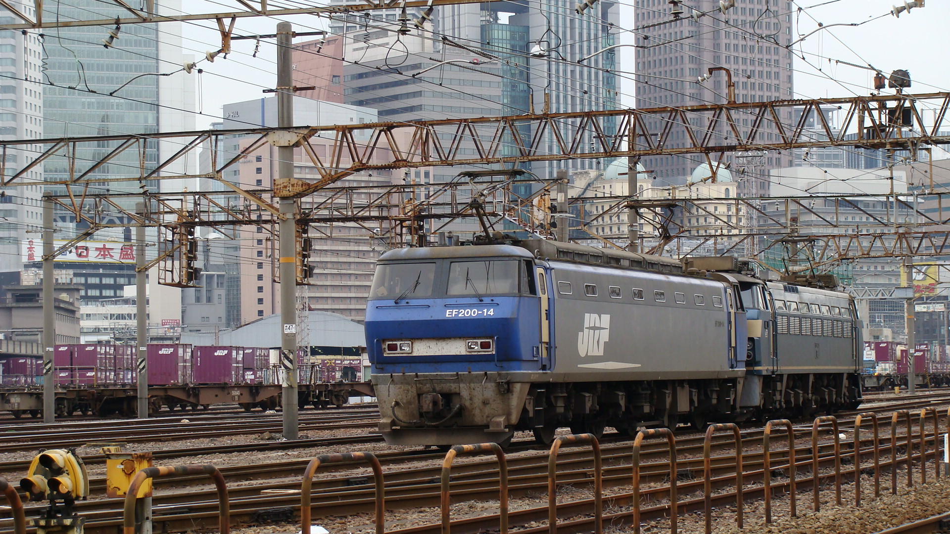
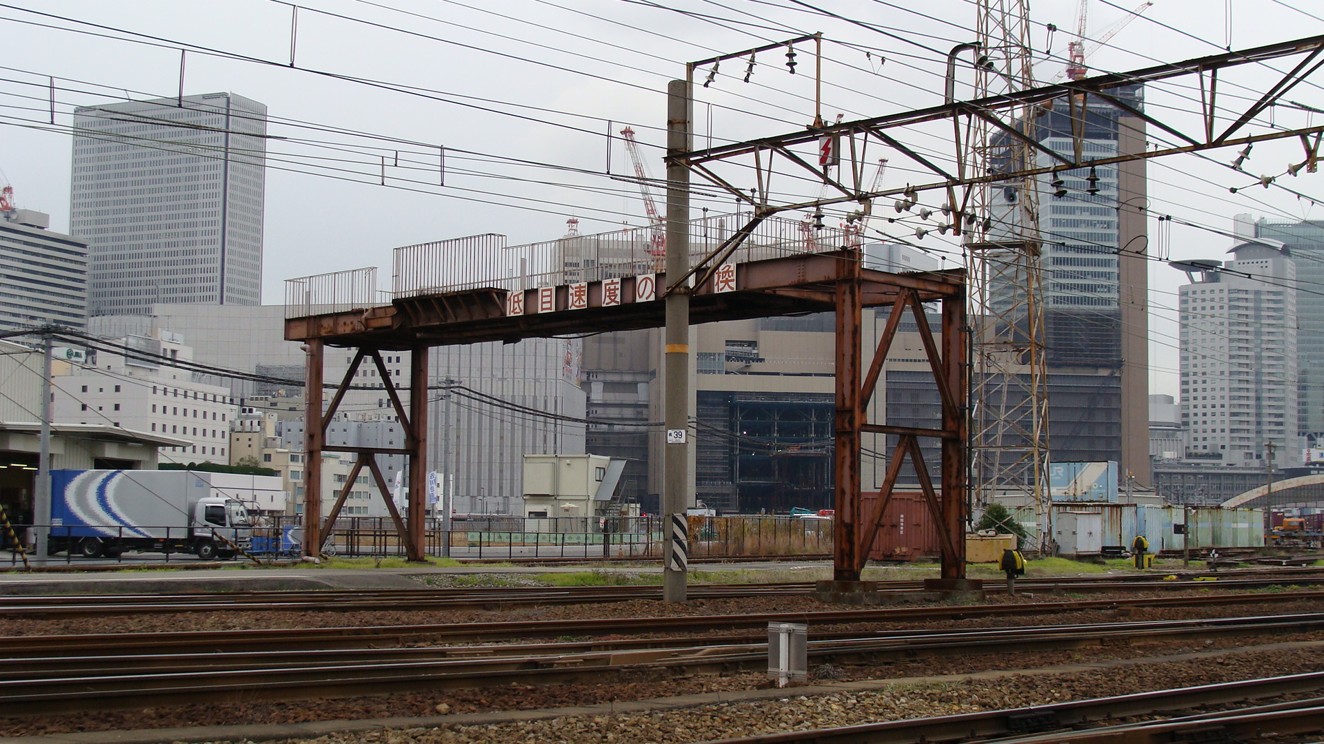
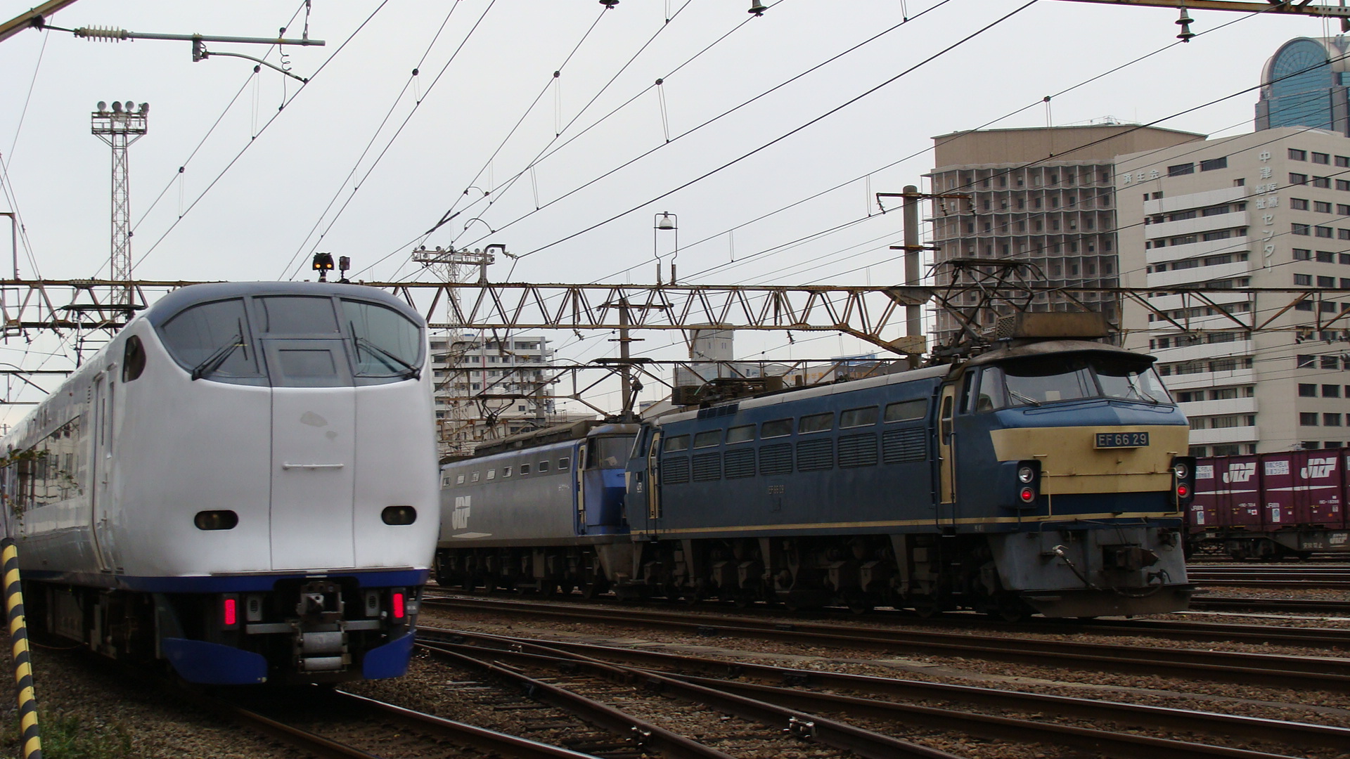
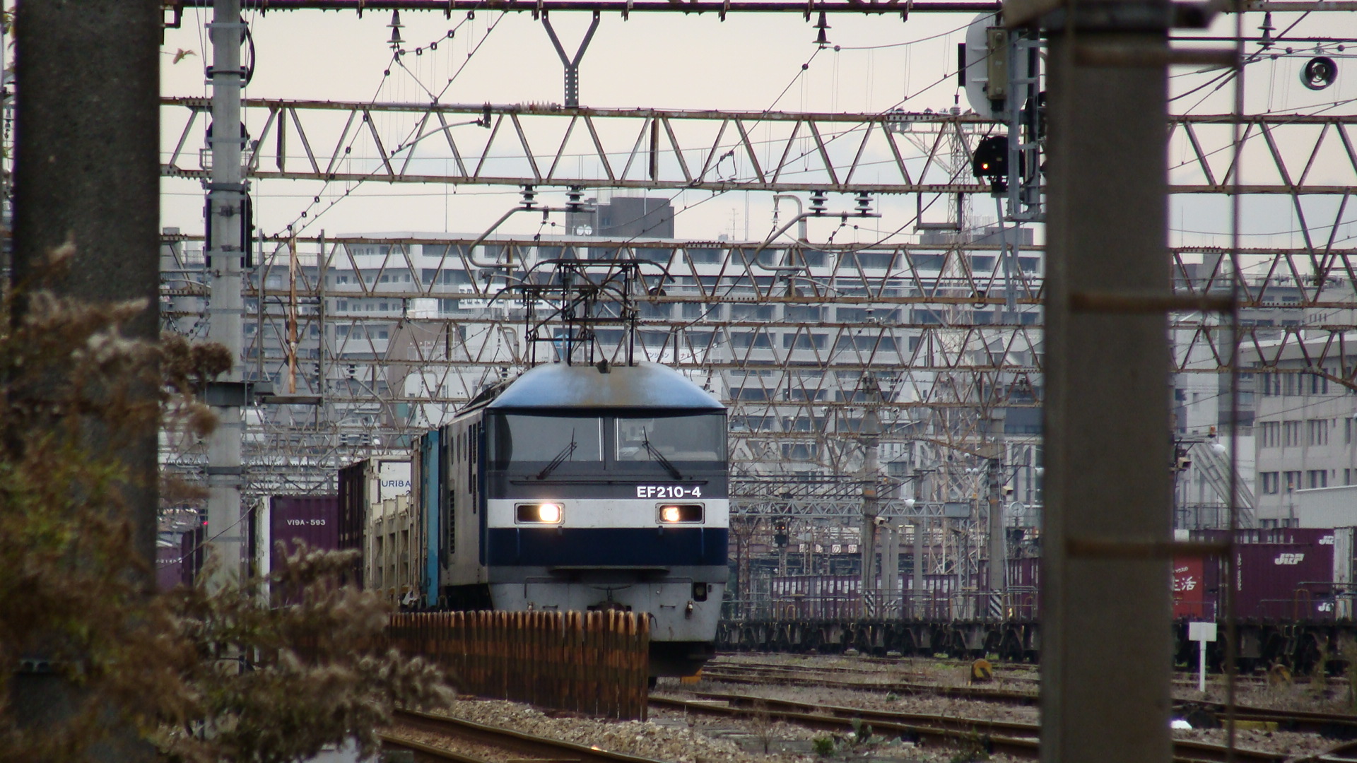
Umeda Freight Yards
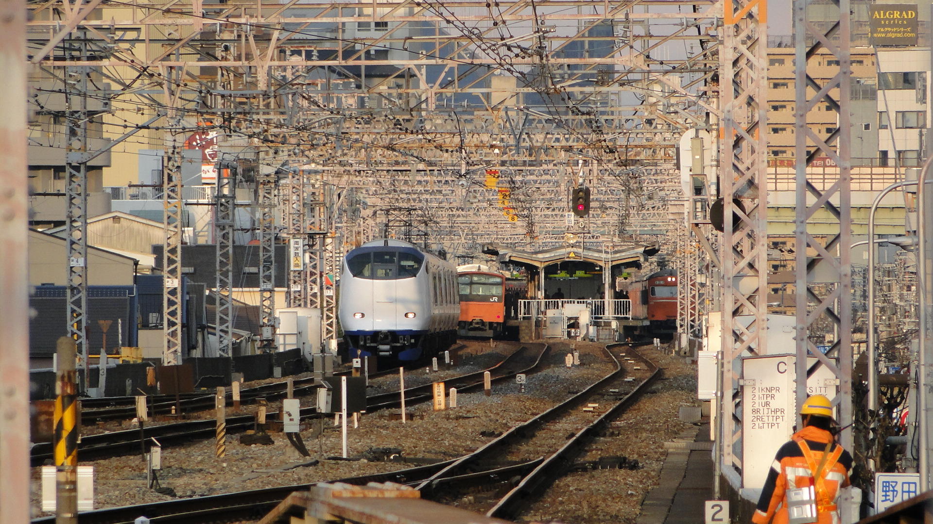
Another favourite place of mine is the Umeda Freight Yards north-west of Osaka Station. This yard seems to be shrinking everytime I go there (due to construction of new buildings), but is often receiving traffic as the west-most lines are dedicated to freight from Shin Osaka and further on to Kyoto. These lines are also shared by the limited express trains that bypass Osaka Station. This includes the Ocean Arrow, Kuroshio and Haruka (to name a few.) Seen below is a Haruka service returning from Kansai International Airport to Kyoto via Shin Osaka. The lanes are also used by the M250 on it's way to Sakurajima.
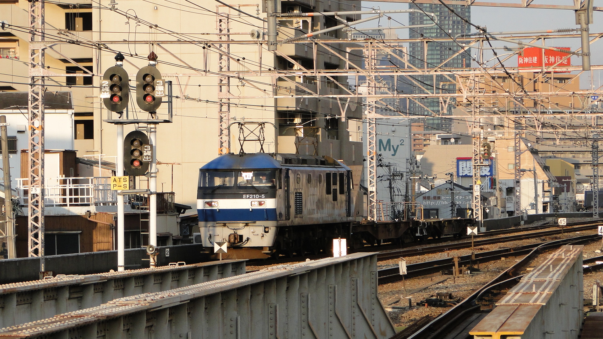
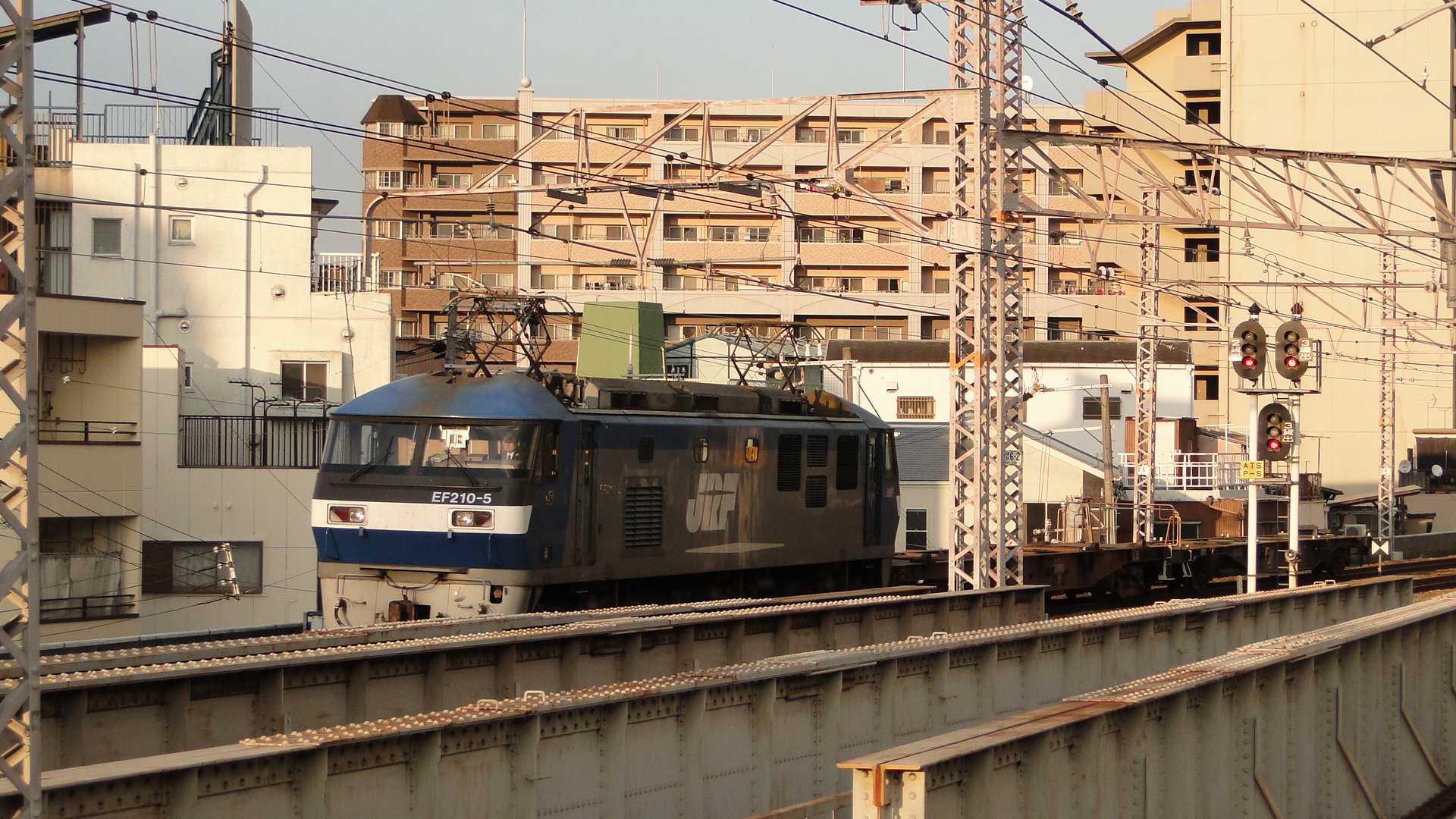
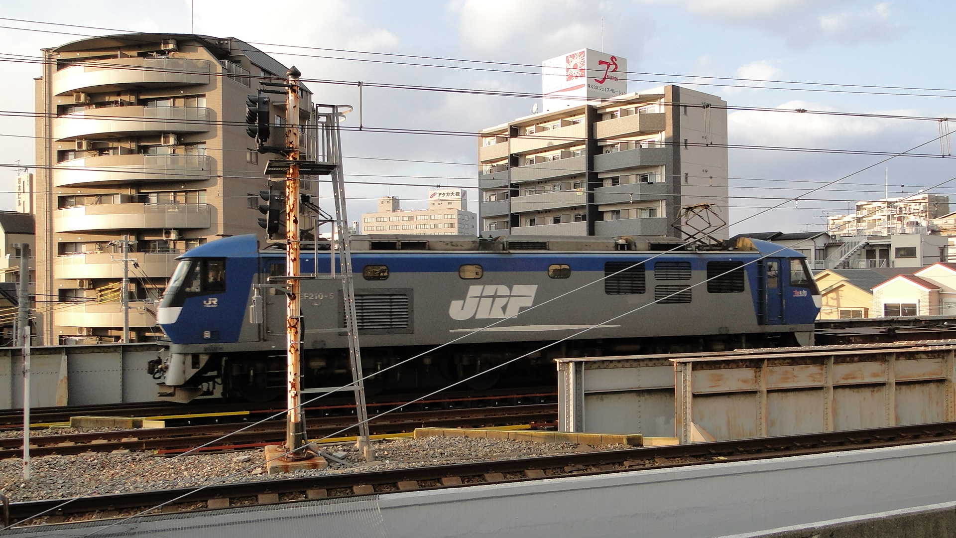
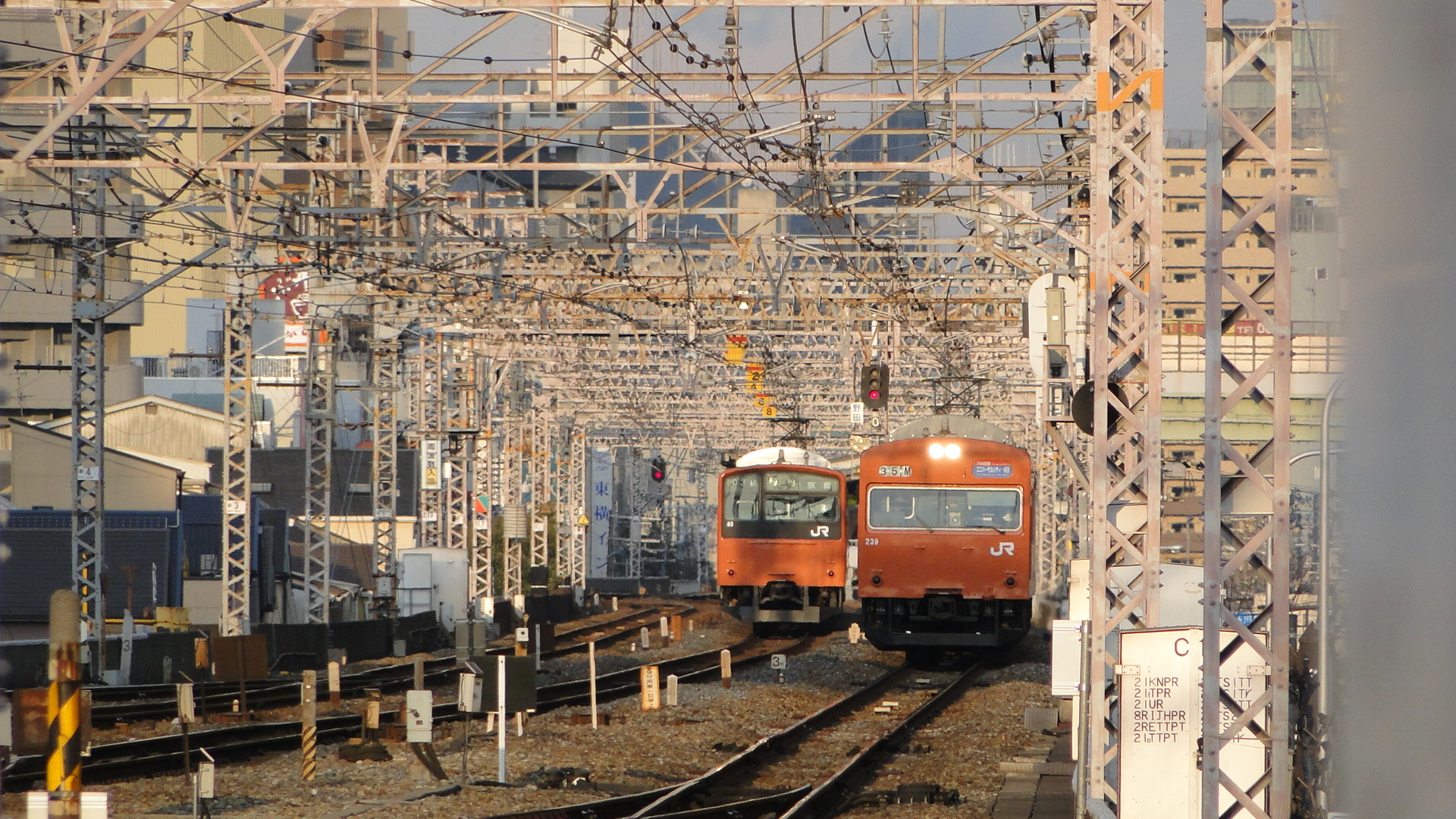
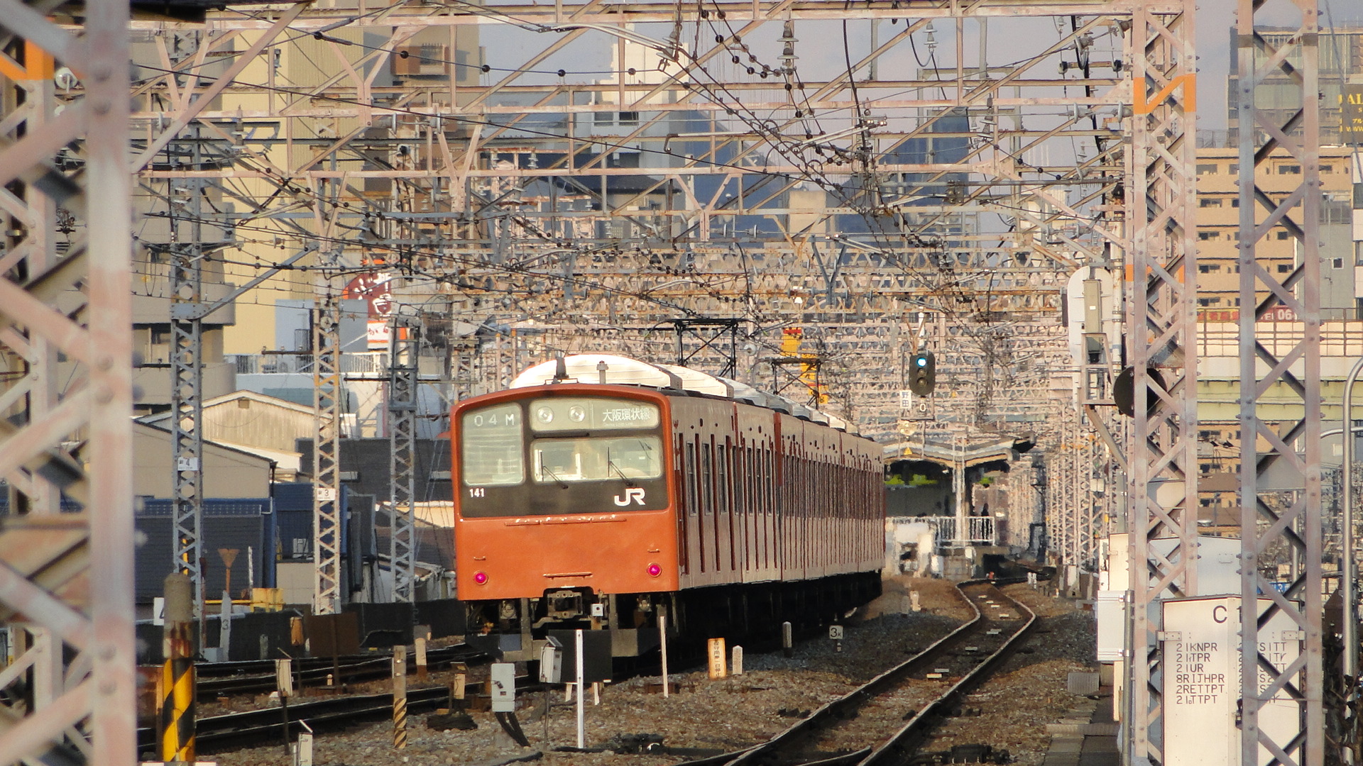
Noda Station
This station on the loop line has meant nothing at all to me before; infact I resented stopping at it on local trains as I would have been able to get to Osaka quicker if it hadn't existed. This trip was, of course, different as it was my closest station. I also had Noda-Hanshin but my JR Railpass dictated a lot of travel paths.
On the south side of the station is a "Tetsudou Toshokan" or "Railway Library". It turns out you can pay 180yen for 30minutes of access to everything they had available. I snuck a peek from the stairs and saw shelves of maps, diagrams and manuals... but didn't enter. They'd only be picture books to me! (Unfortunately..., this shop has now closed as of 2017)
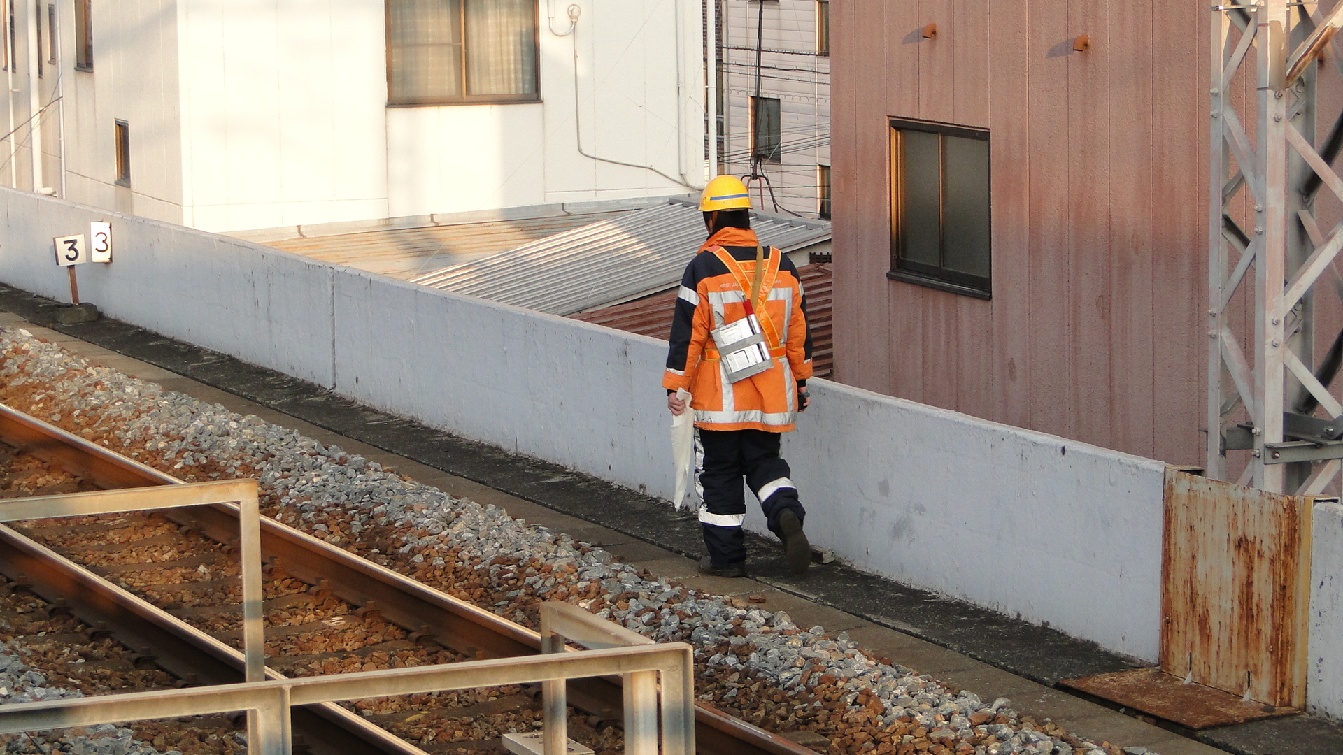
On my last day I took advantage of the sunset and photographed everything coming towards the station (actually, I lie, most of this was from Nishikujo, but the effect is the same.) I was impressed to see a freight locomotive coming towards me and laughed when I saw it towing only 2 flatbeds to Sakurajima.


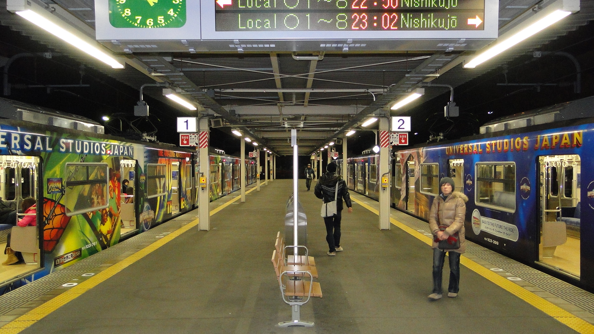
Sakurajima Station
This is the end of the Yumesaki line, whose main purpose is to serve Universal Studios Japan. I just thought I'd add in some photos of the USJ liveried loop line EMUs.

Sapporo and the Oigawa Railway
The Oigawa Railway is still my favourite railway in Japan (Second is the Eizan/Eiden Dentetsu in Kyoto) and I, again, visited it on my most recent trip to Japan. I also went back up to Hokkaido, this time actually spending time in Sapporo and returning via a different Night Train.
Sapporo
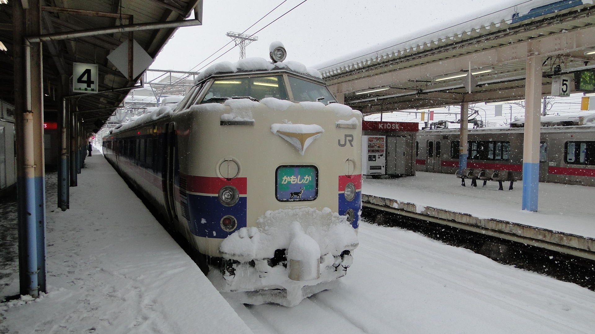
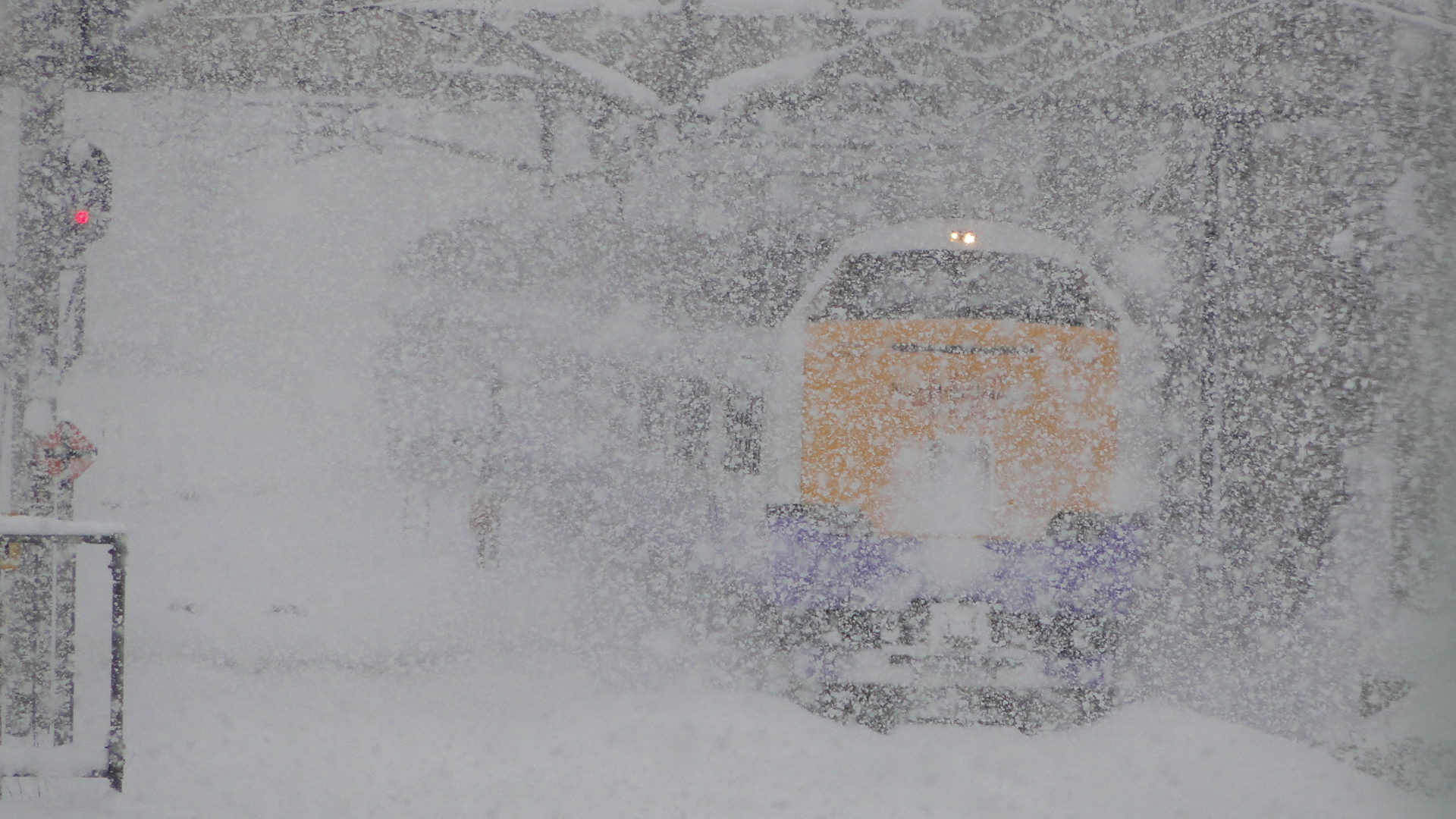
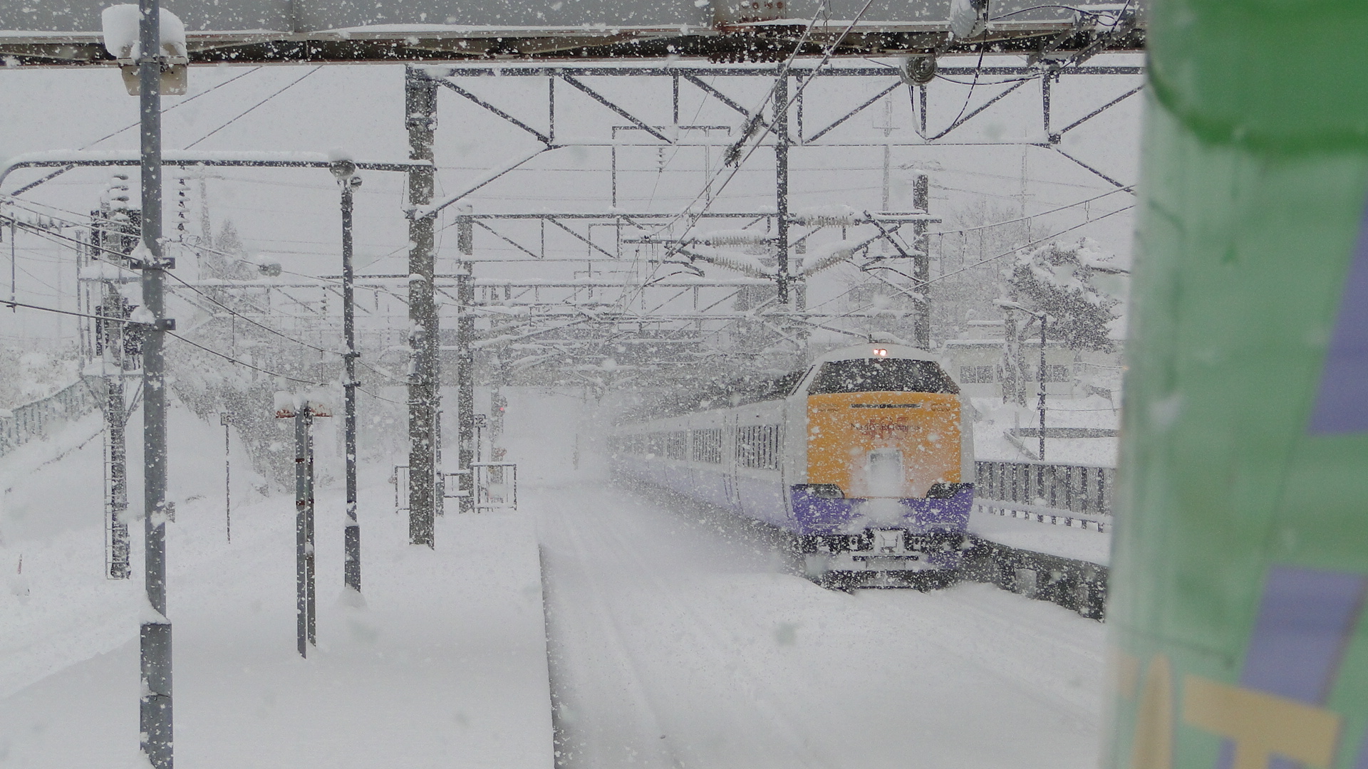
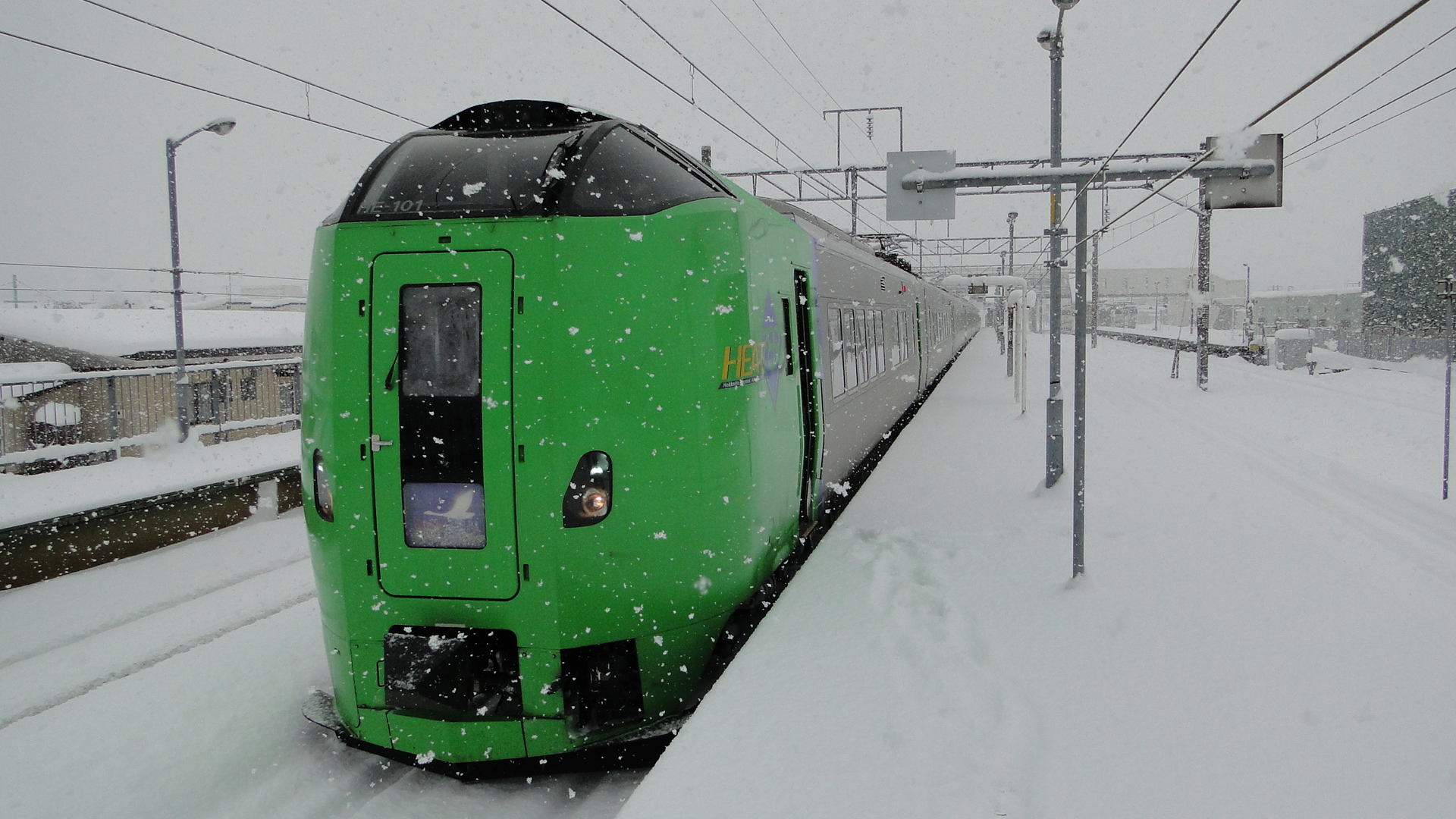
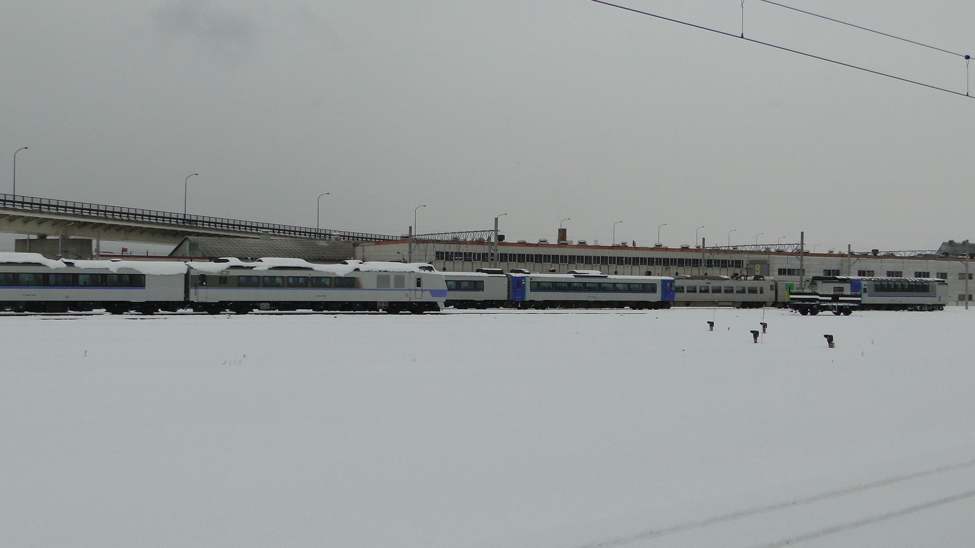
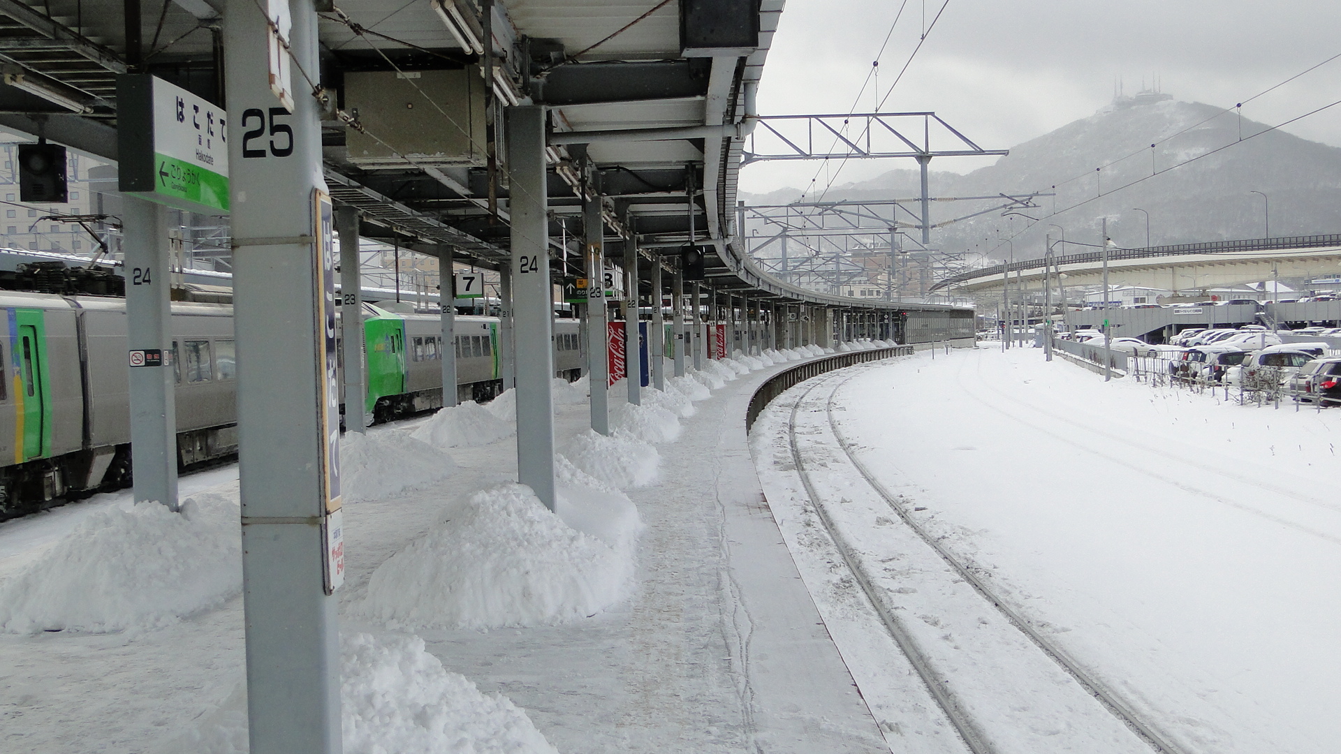
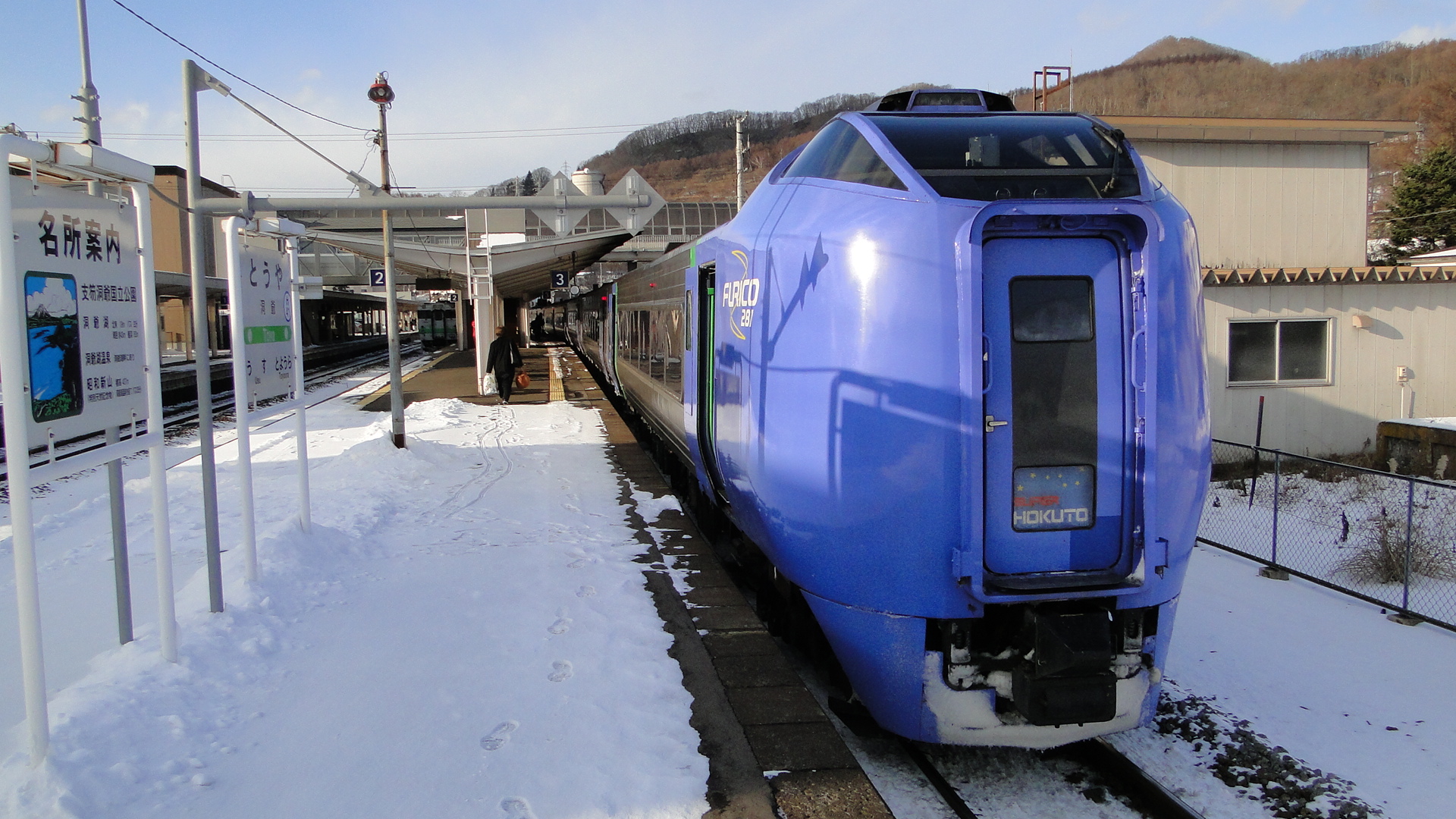
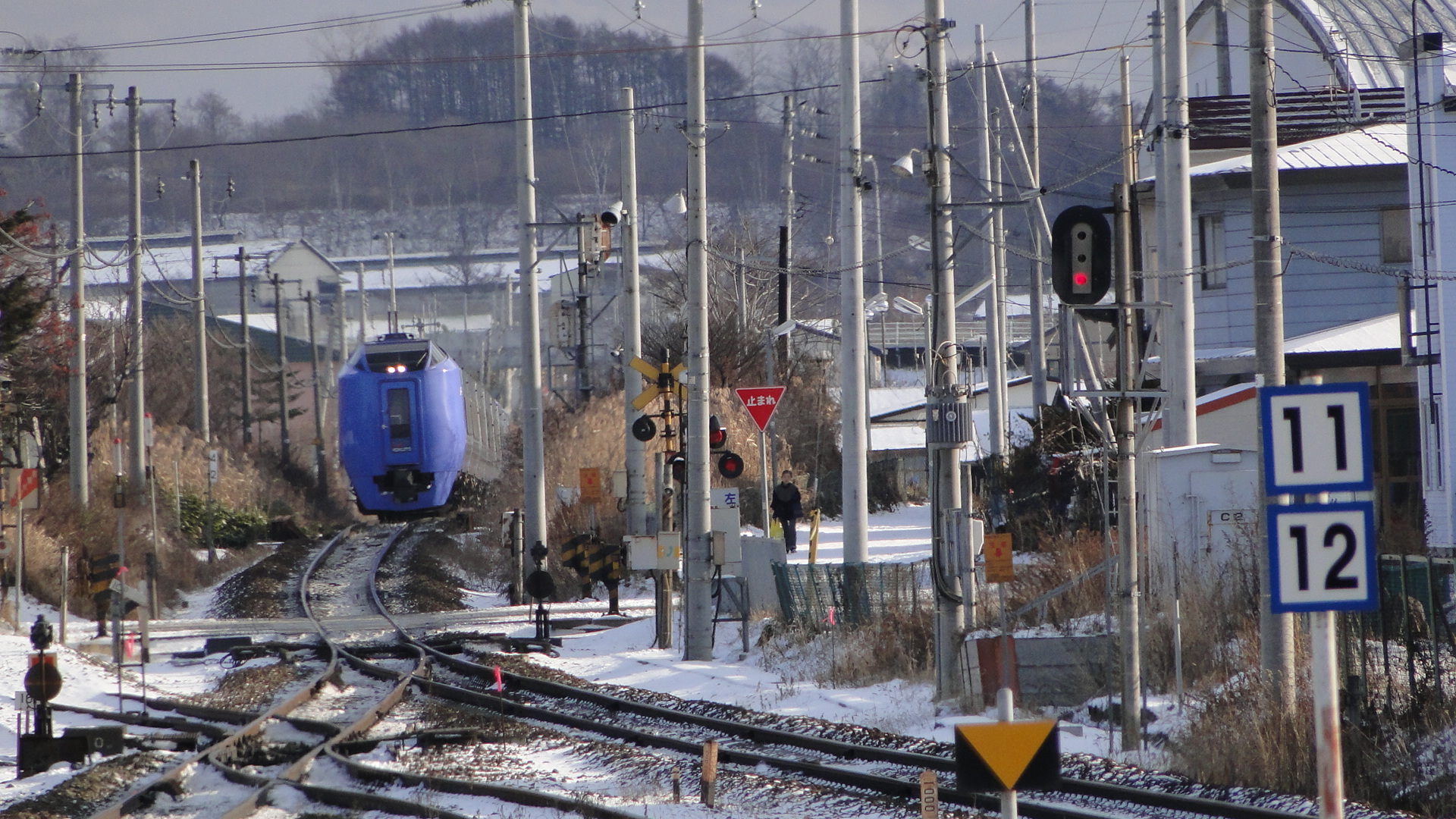
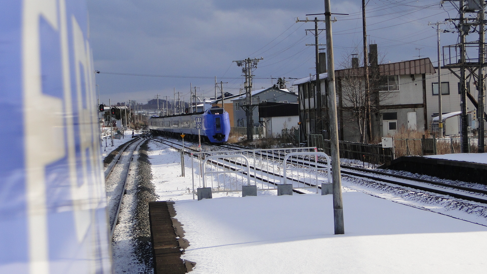
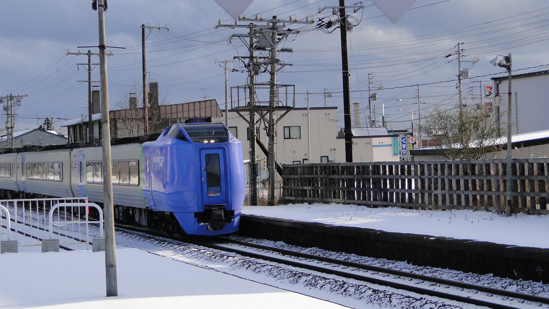
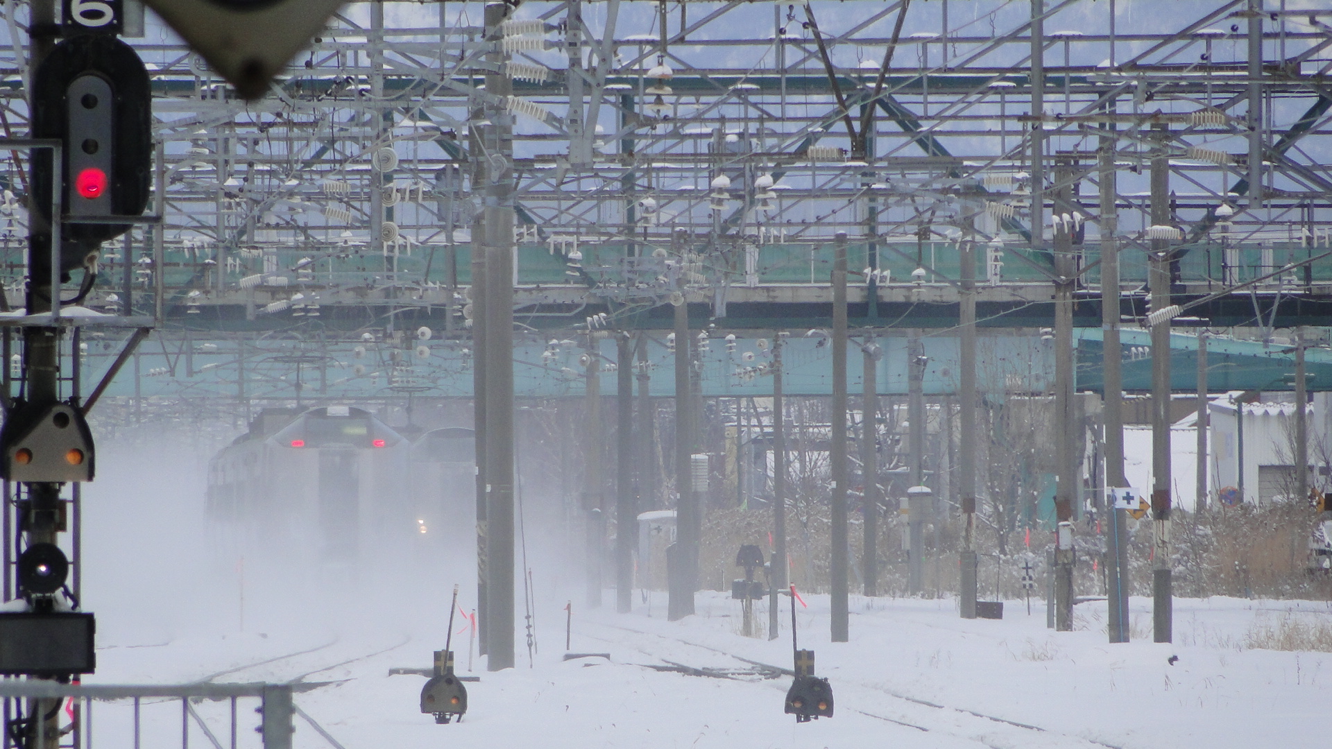
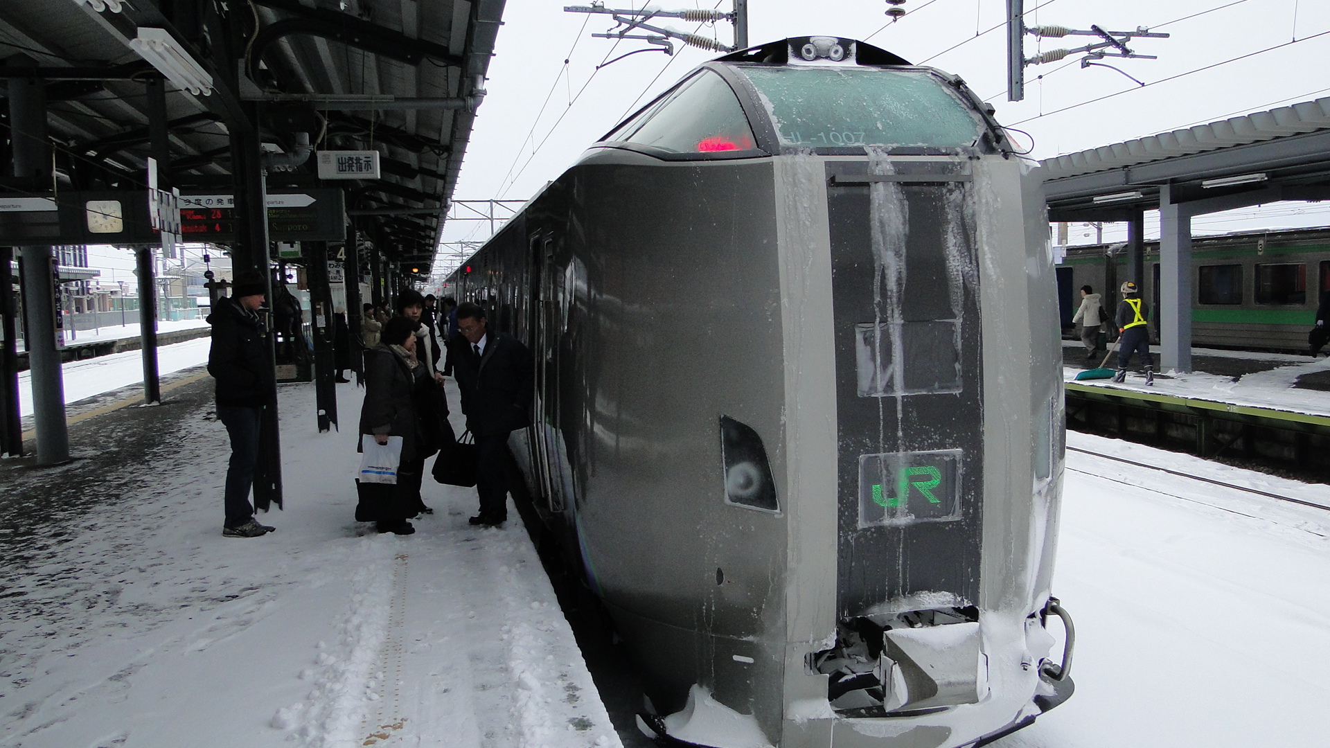
Two words... "Damn cold". I think we averaged around 3 degrees celsius whilst there but loved every minute. Crossing road intersections was a deadly game as you quickly found the ice under the snow and watched as either you or others around fell flat on their asses. All this snow also gave express trains a challenge, but the effects are magical when you get to see one at full speed.
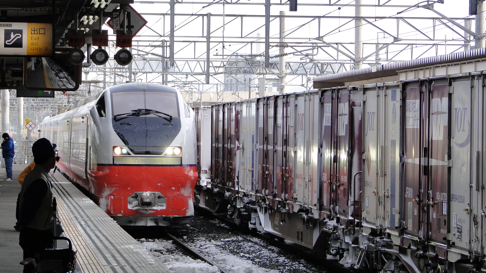
I actually started from Hachinohe and took the Super Hakucho and Hokuto to get to Sapporo. There was no snow falling in Hachinohe but the ground was icy. As we got closer to Aomori the snow on the tracks got thick (I love the front windows in both express services) to the point where you couldn't actually see the rails. I was disappointed to not see any snow plough trains in action.
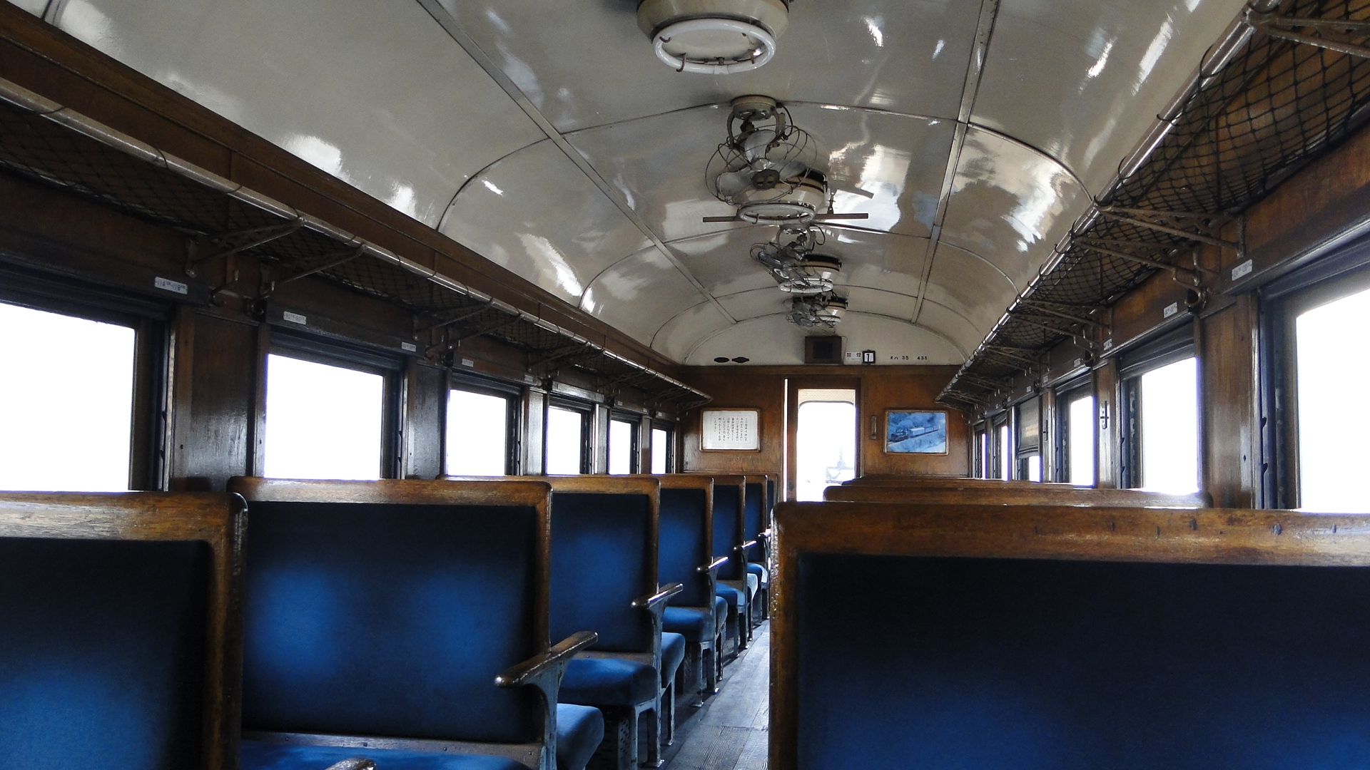
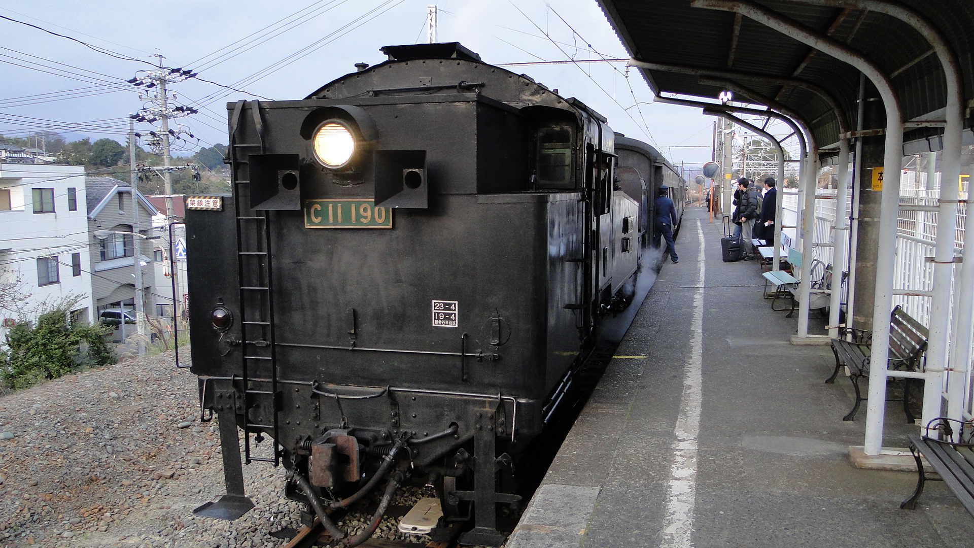
I didn't really get to venture out too far, but the first night there was spent in Otaru. This is a beautiful "canal city" and I happened to stumble upon a steam locomotive when first arriving.
Unfortunately it was cheating with a DE10 up it's rear end. Of course this is required as a fail-safe on mainlines, but you could hear the DE10 doing a lot of the work.
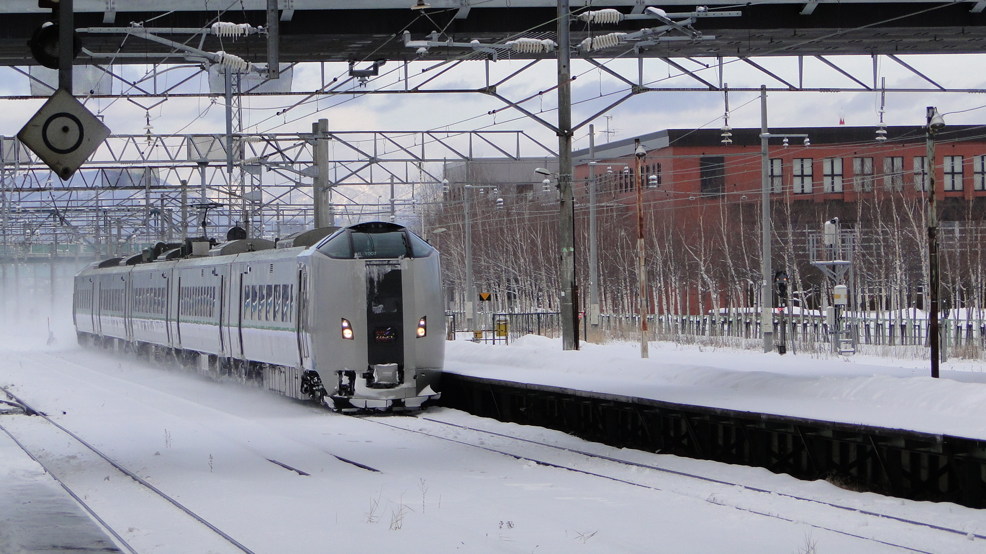
Returning to Sapporo I saw all sorts of services and also rode on the Super Kamui and happened to see one pass another.
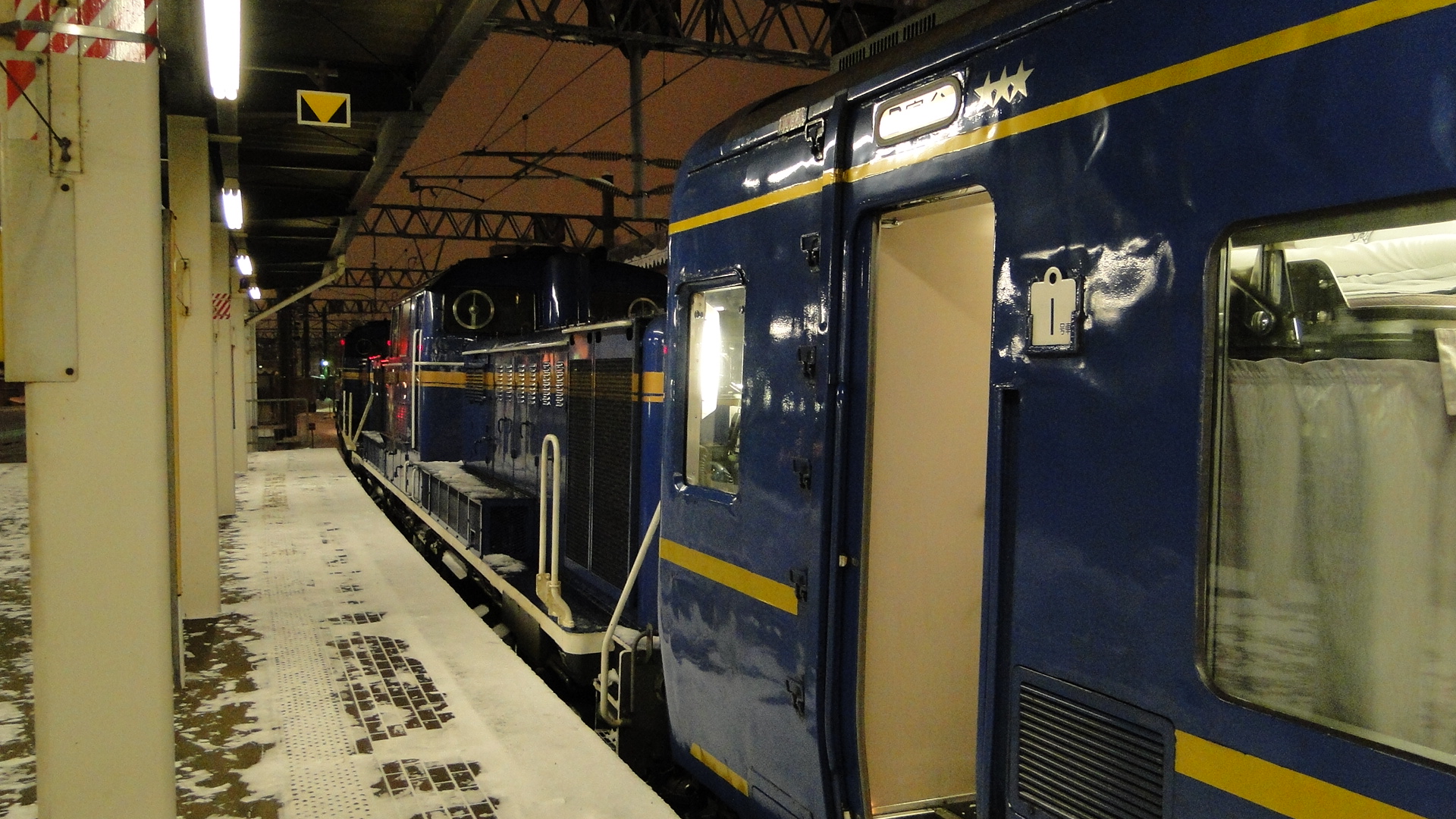
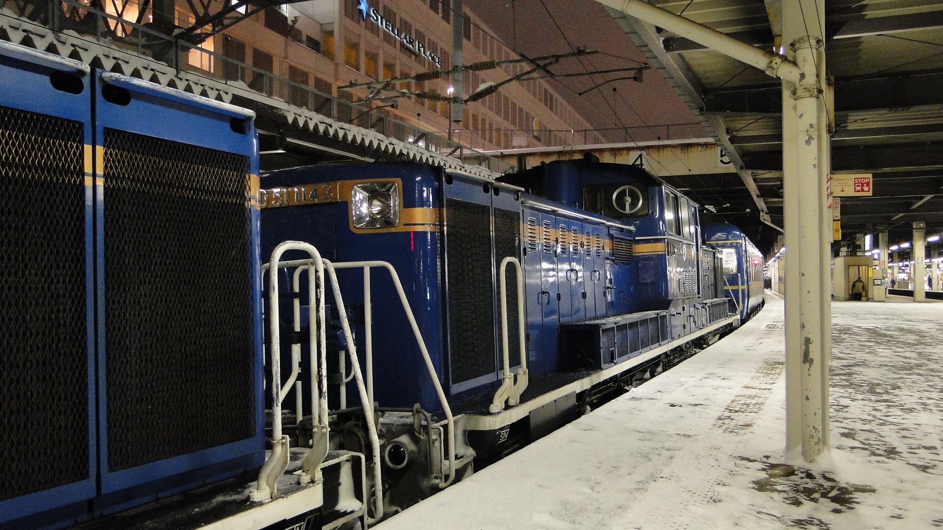
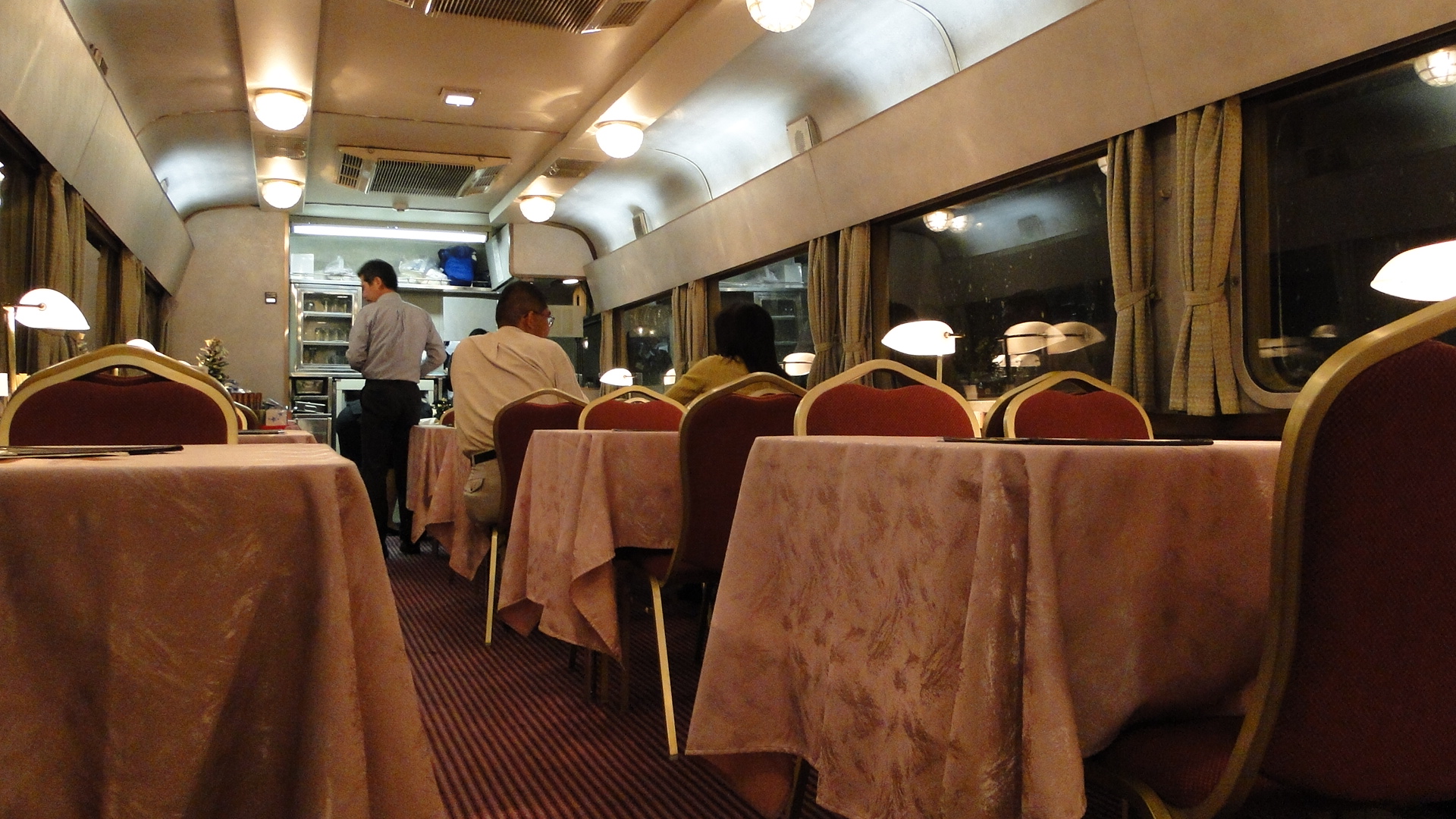
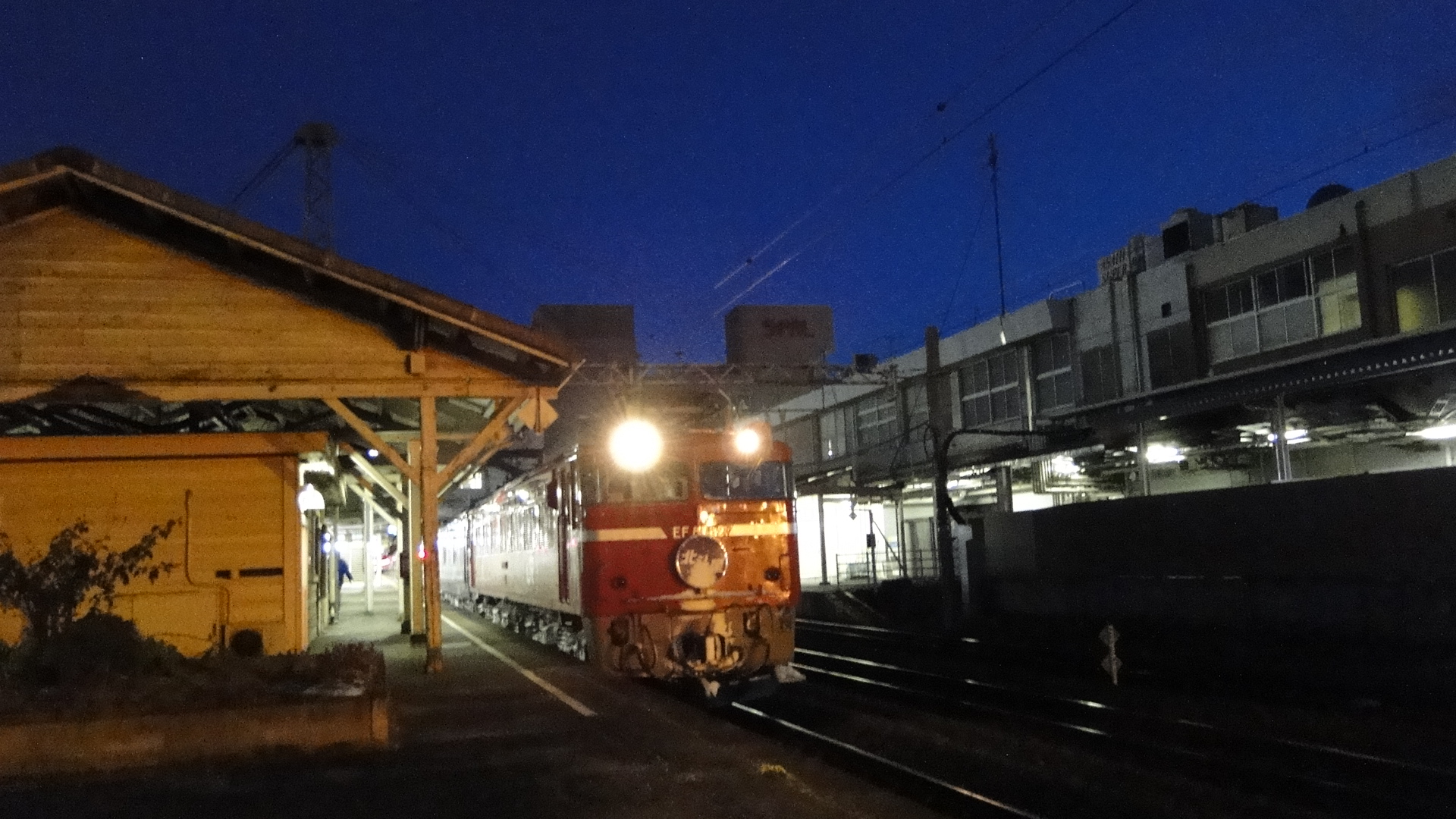
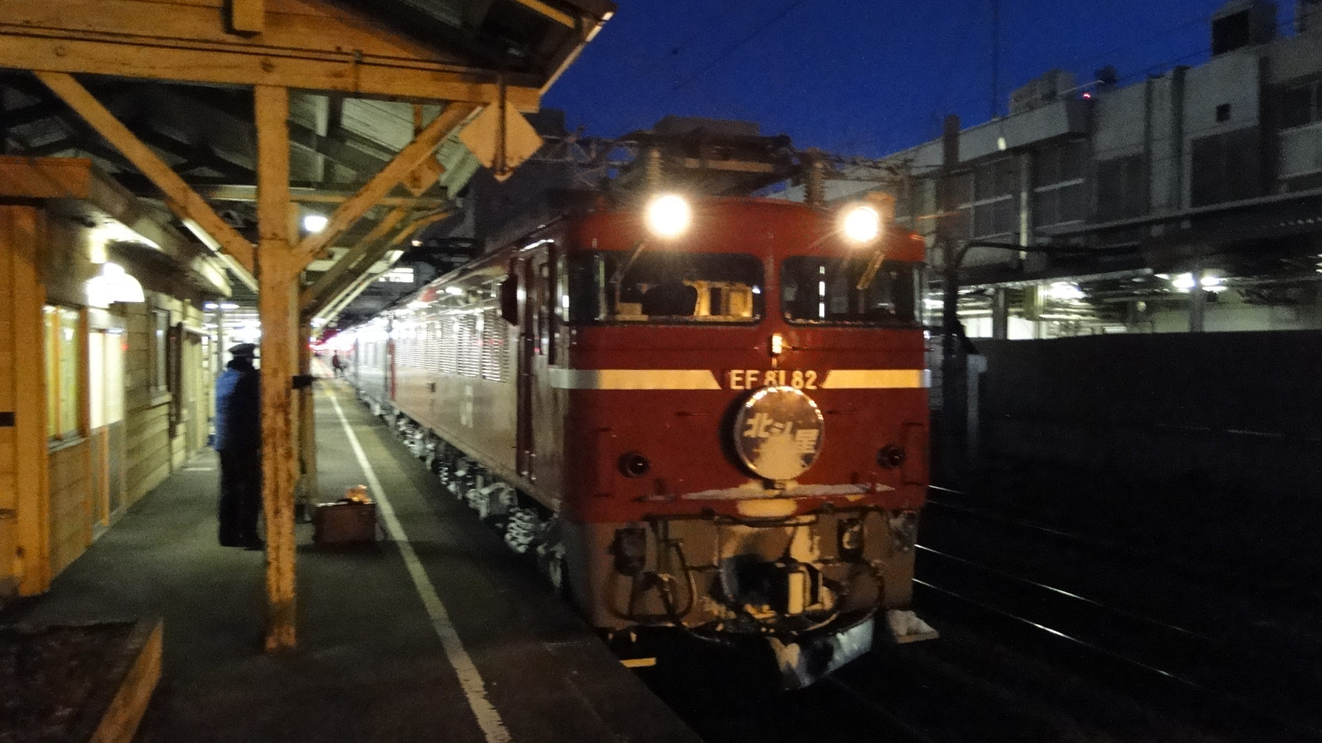
I returned to Osaka overnight on the Hokutosei. I travelled from Sapporo just after 1700, arriving at Fukushima at 0600 to swap to the Tohoku Shinkansen and then the Tokaido Shinkansen. Swapping to the Shinkansens early (instead of sleeping through to Tokyo) meant I saved around an hour and a half in transit.
Oigawa Railway
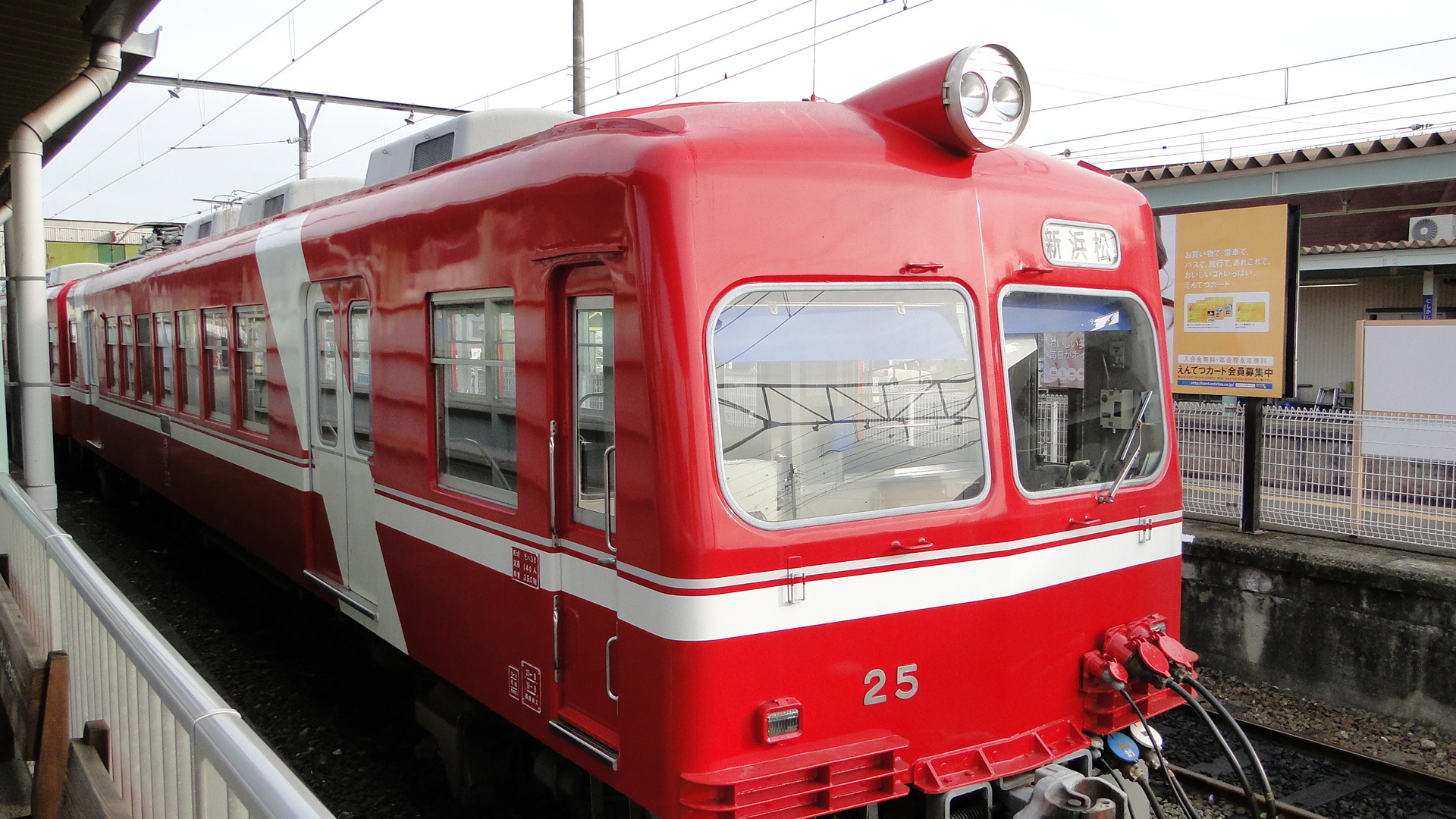
This trip started from Osaka, with a detour via the Entetsu Railway and Tenryu Hamanako Railways:
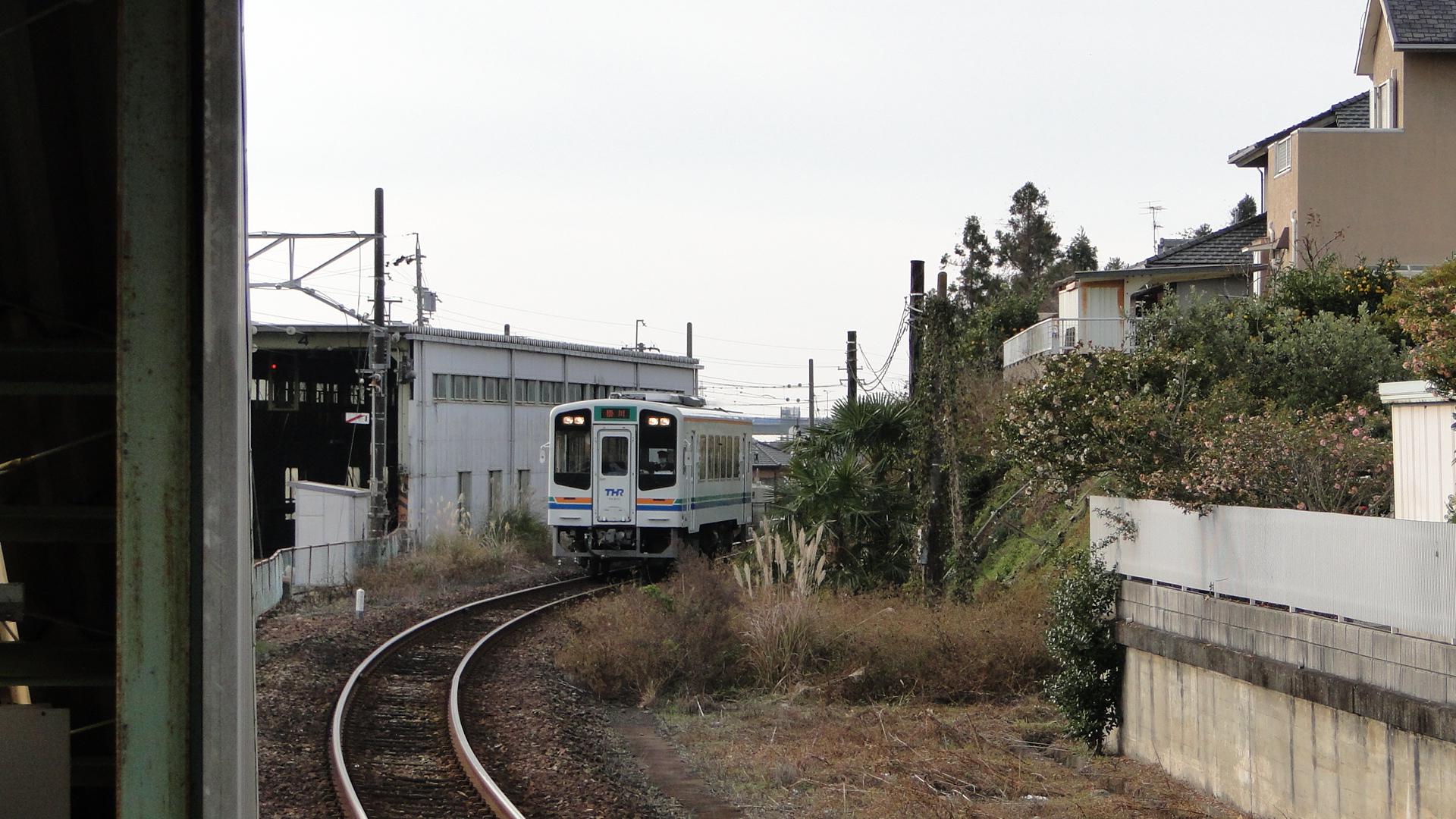
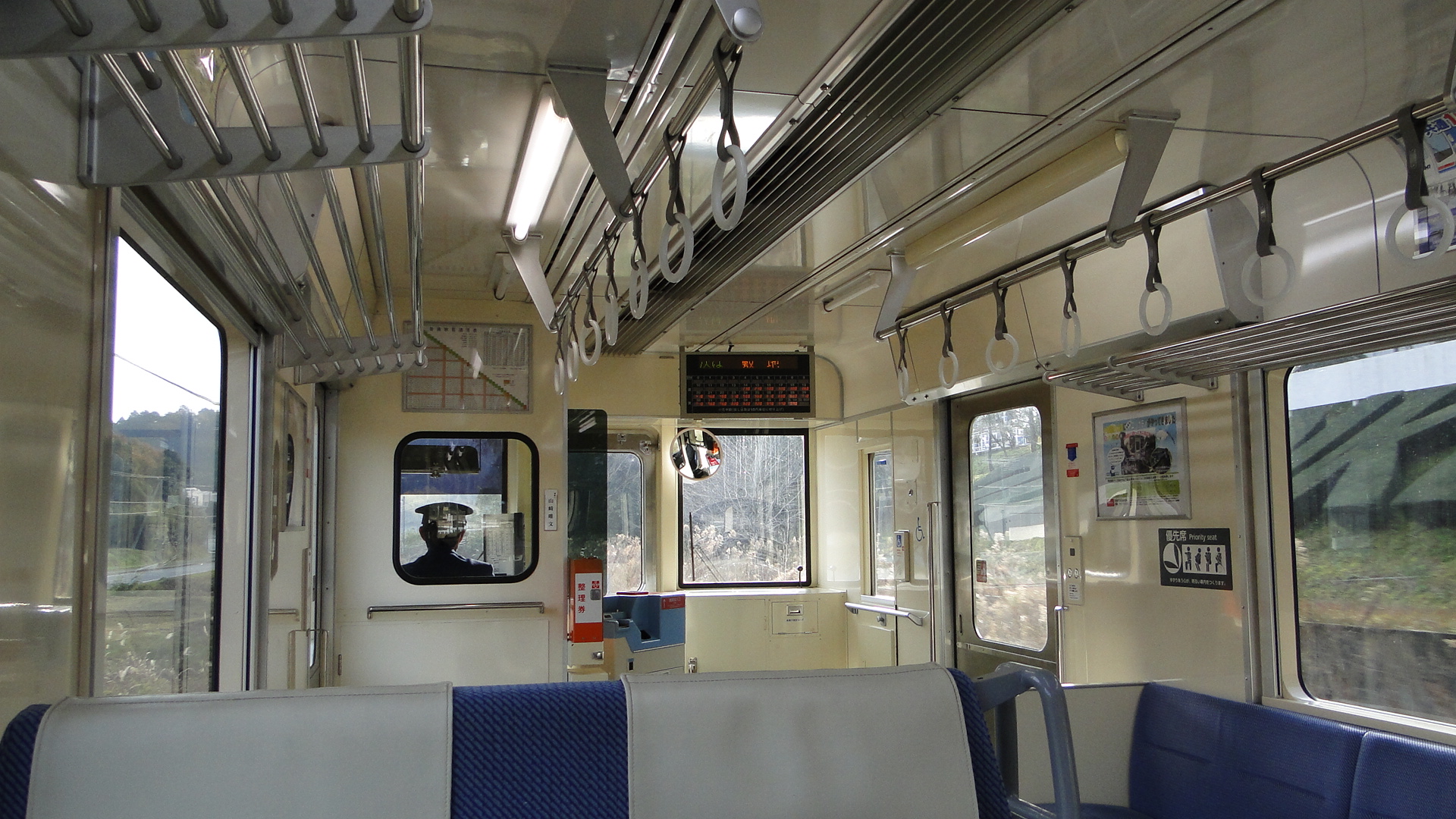
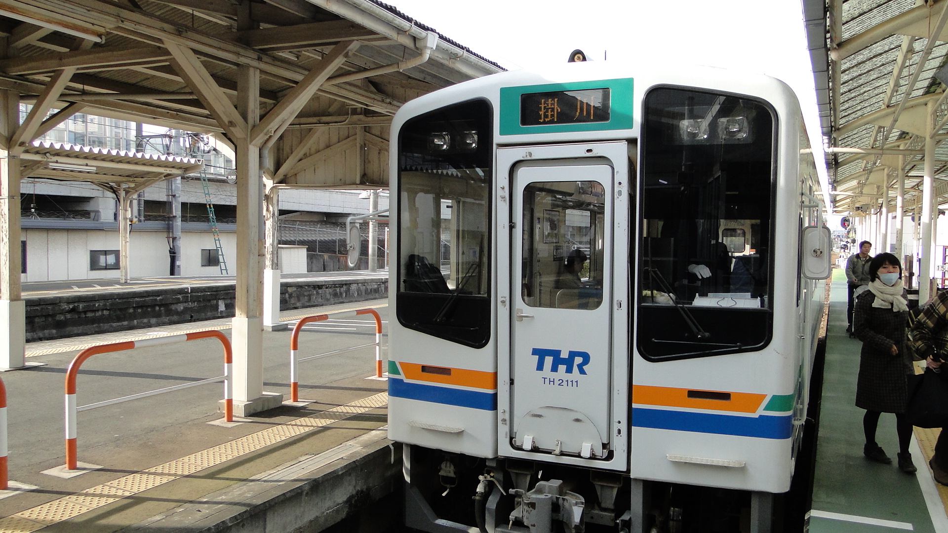
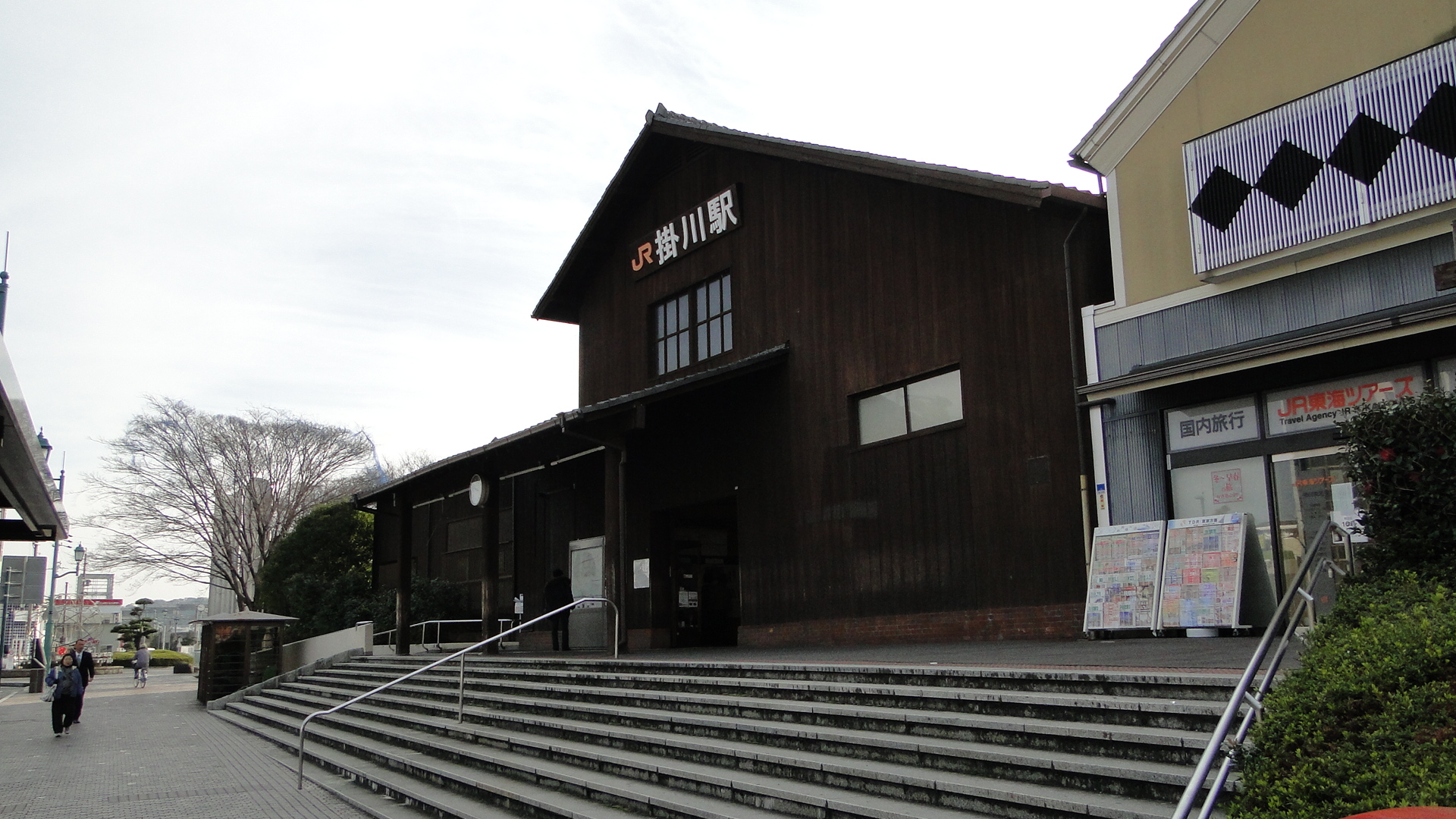
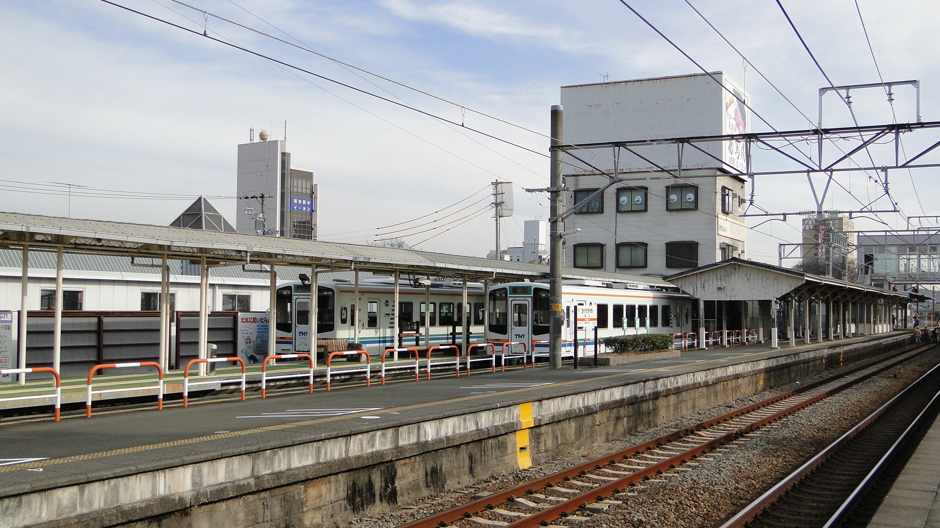
Oigawa Railway is a third sector railway running from Kanaya (JR Hokkaido Line) to Senzu, known as the Main Line, and then through to Ikawa on the Ikawa Line. The line was built to transport equipment and materials to build a dam on the Oigawa River. The Ikawa line is partially a rack railway due to the gradients in some places.
My trip involved travelling through to Okuizumi on the Ikawa Line and staying at the Okuooi Ryokan (highly recommended). I returned via the SL the next day and I also totally recommend this. It was the christmas day special and I booked ahead on their website.
I took a lot of photos, you can find the whole album here... but here are a select few:
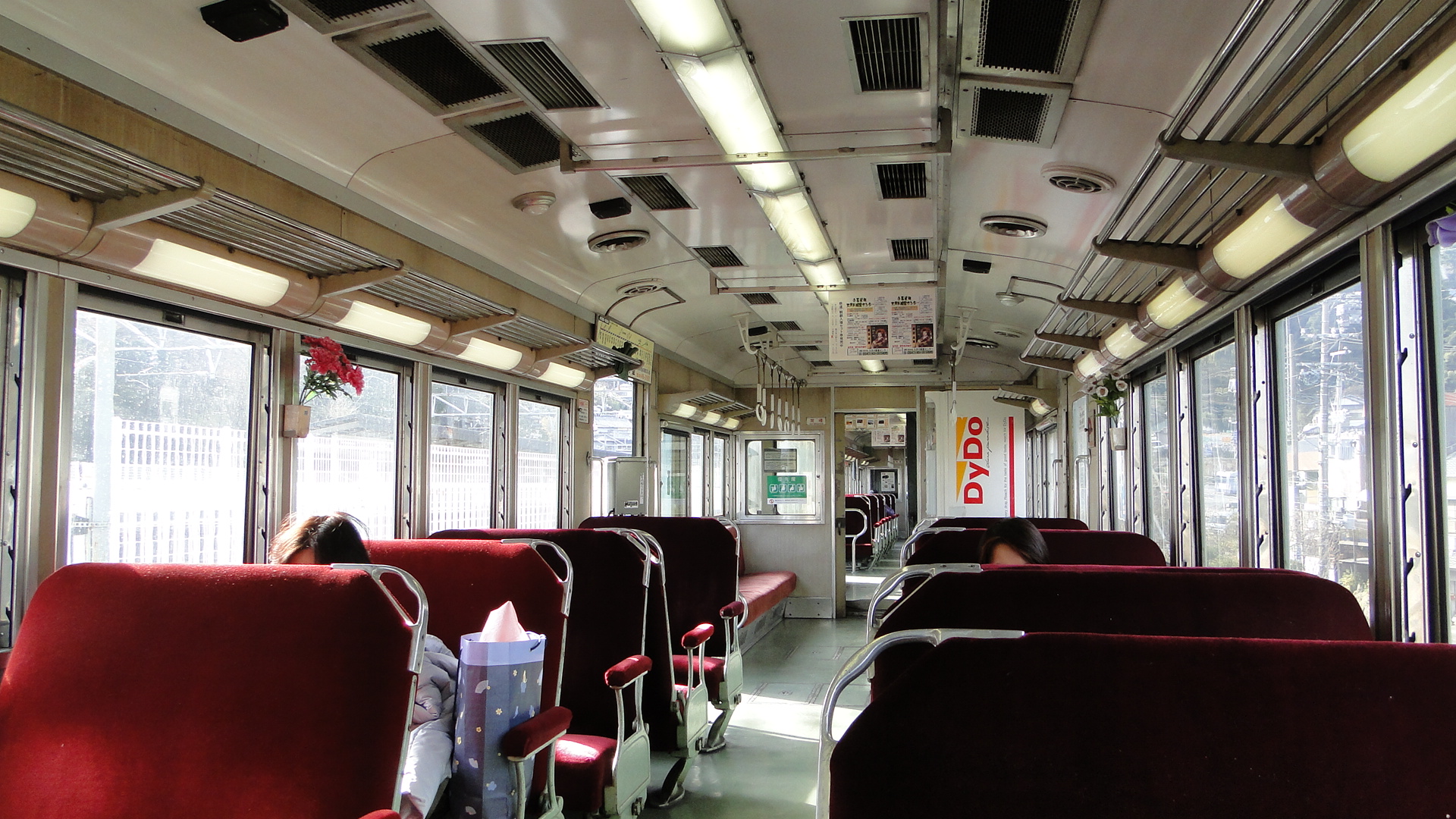
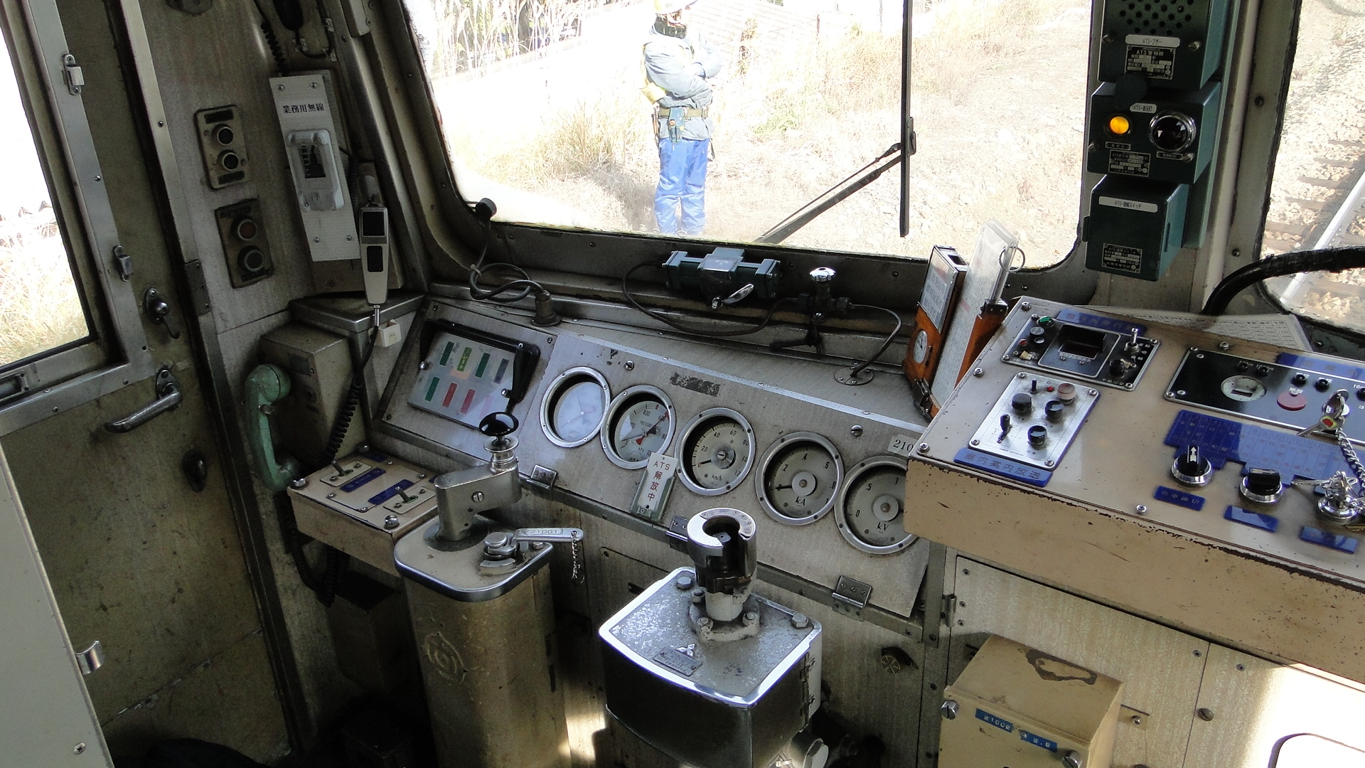
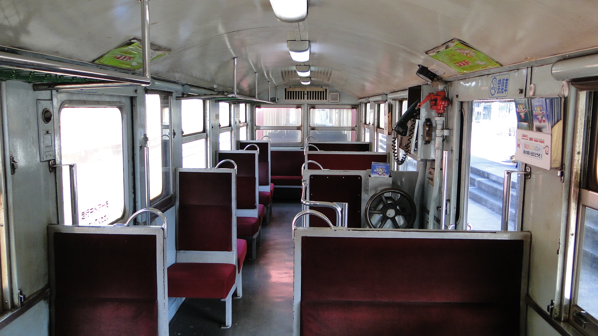
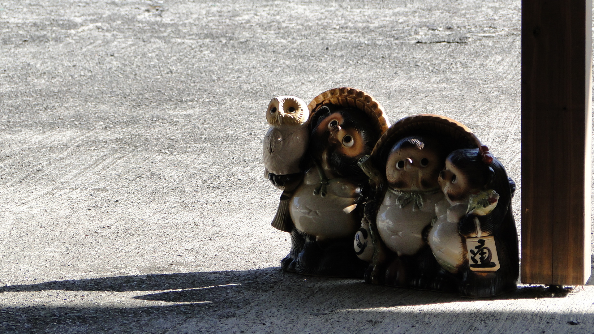
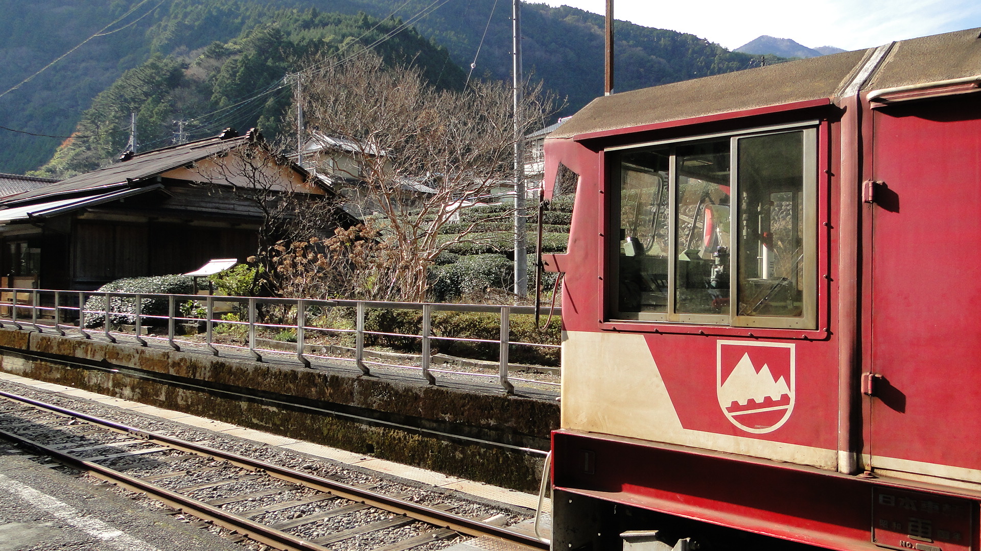
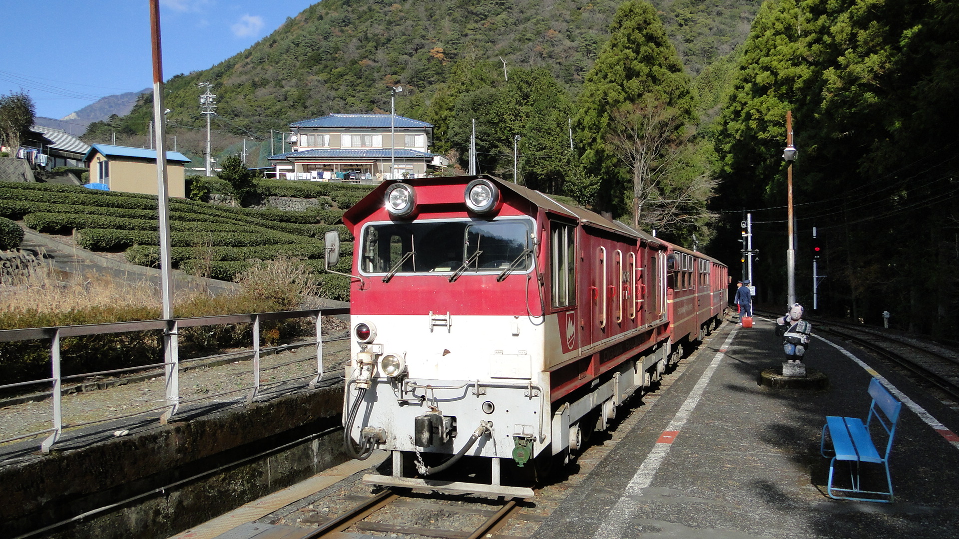
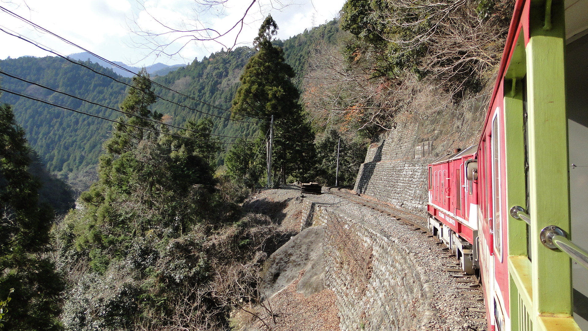
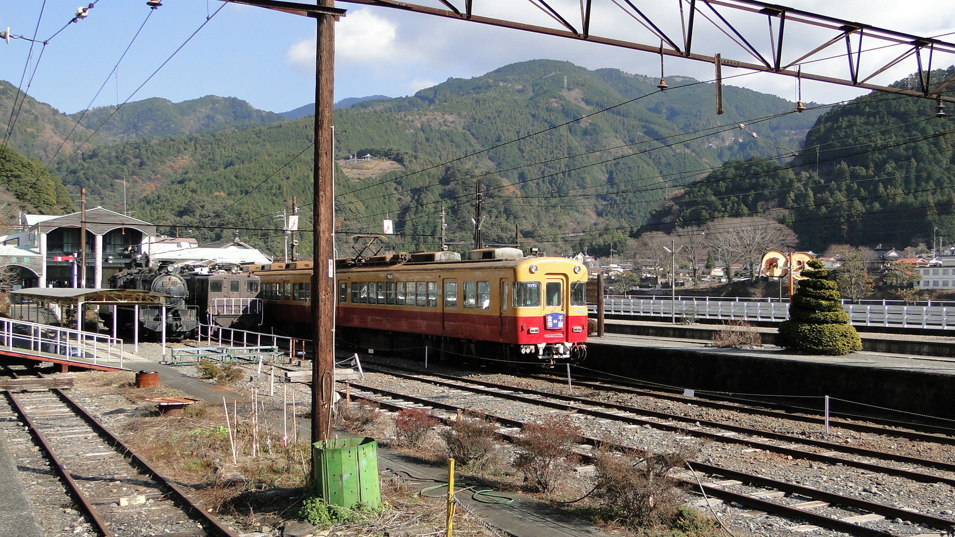
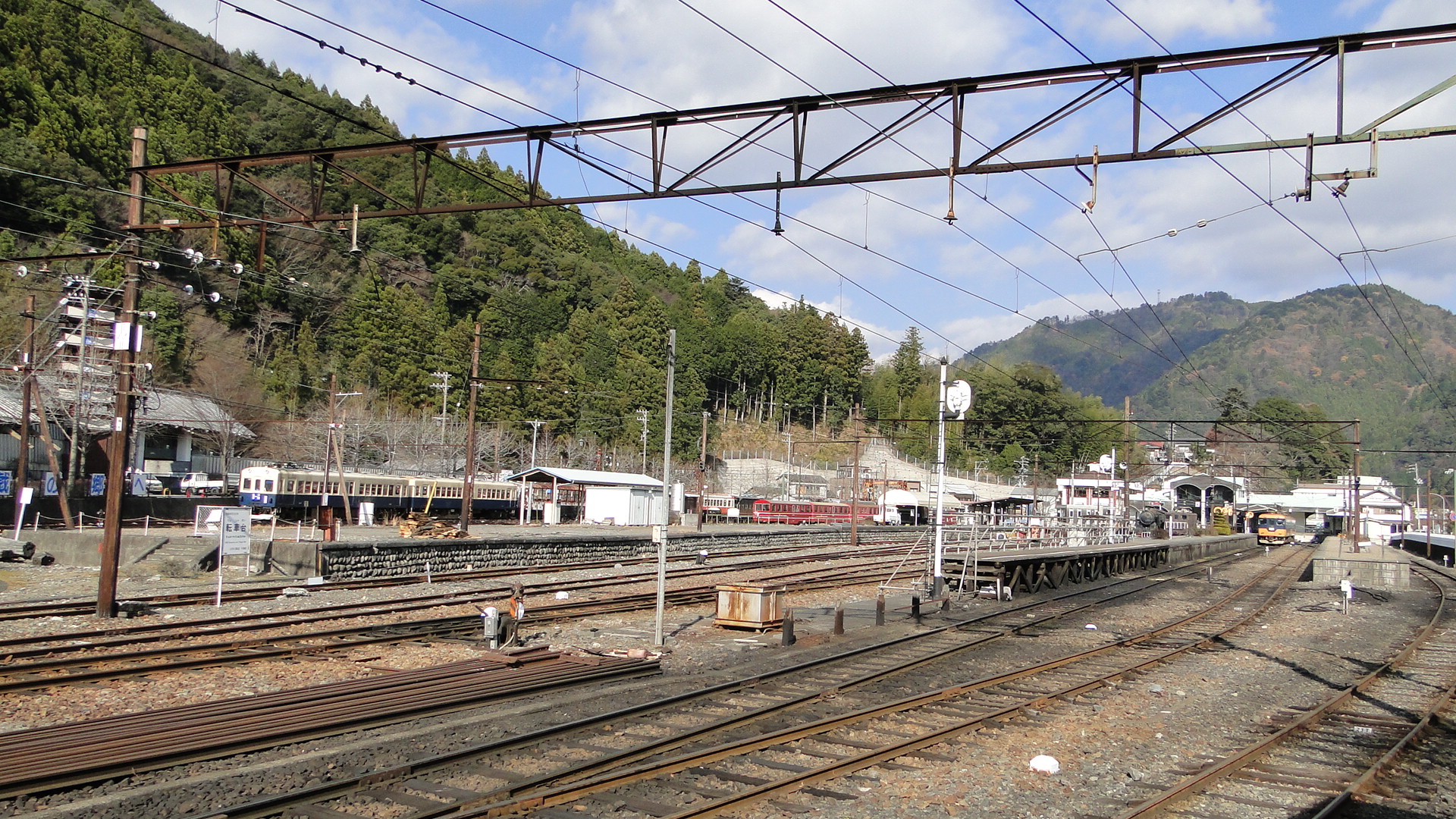
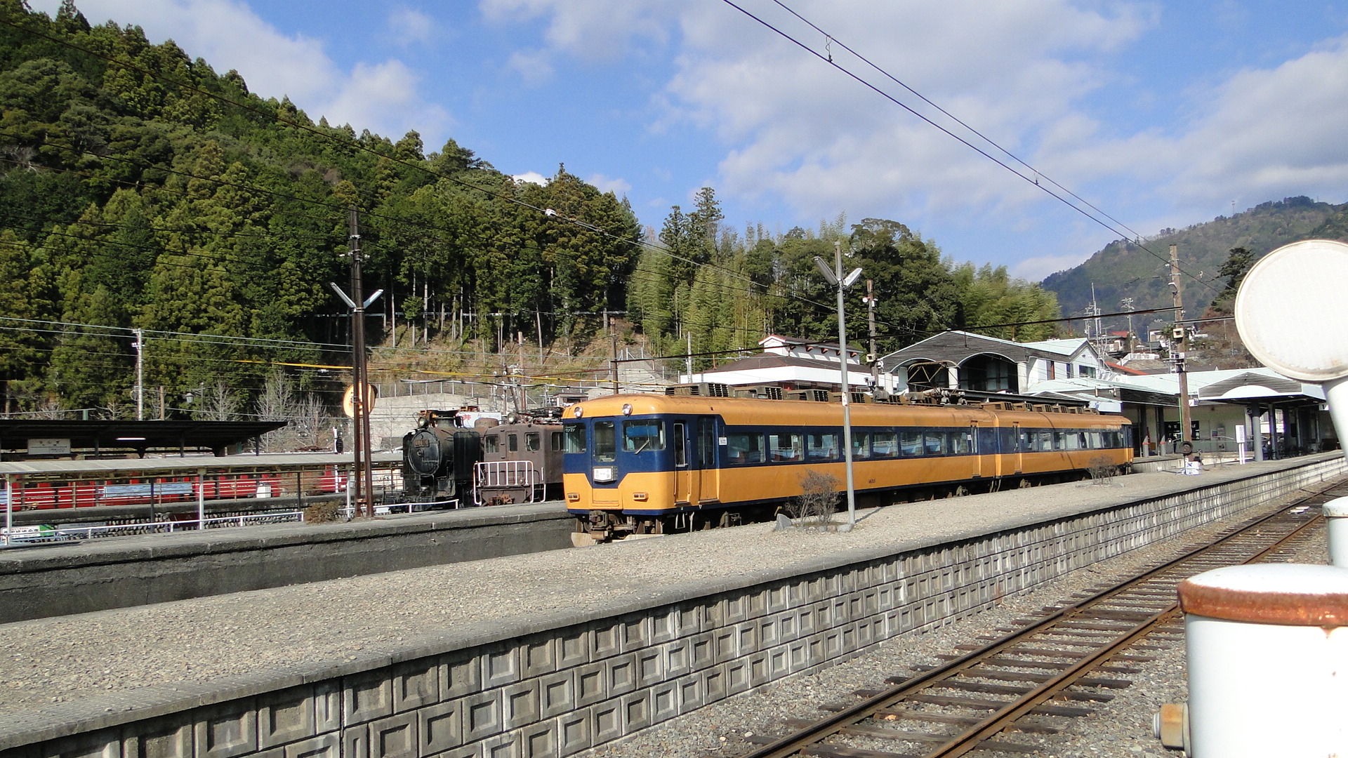
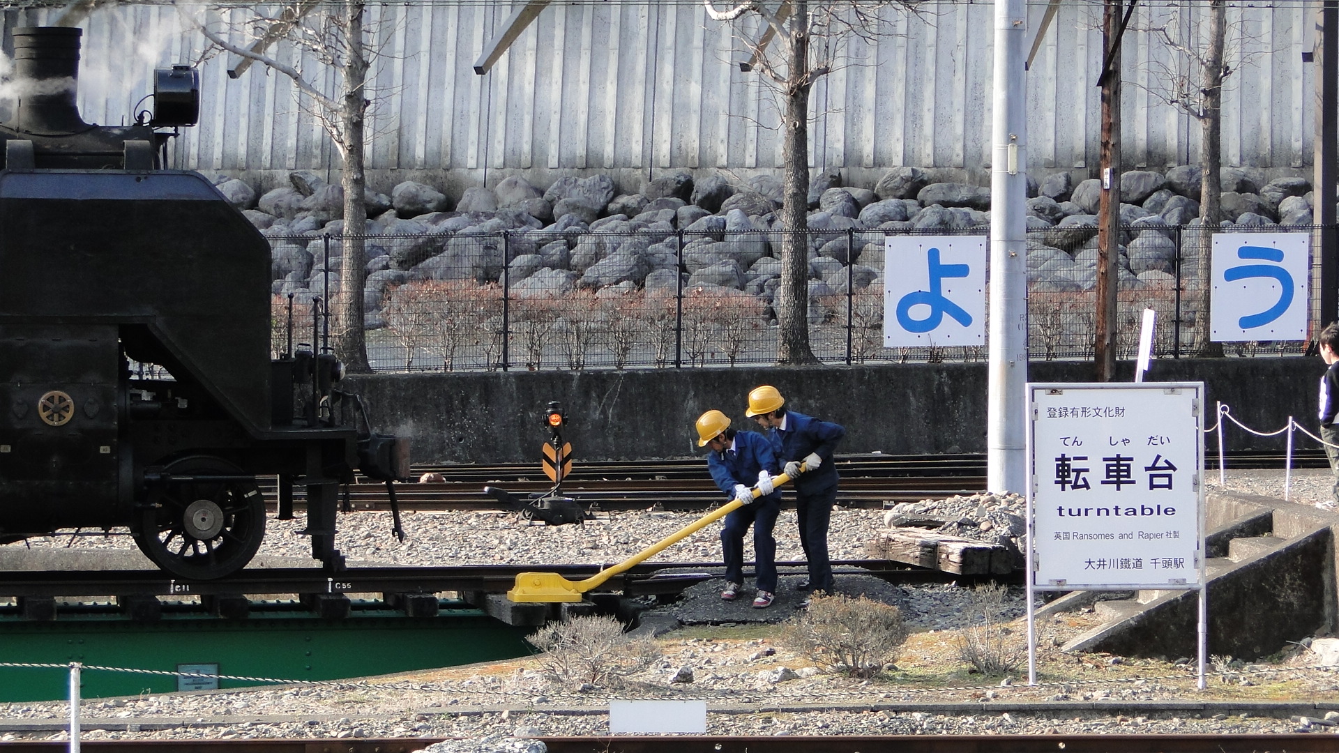
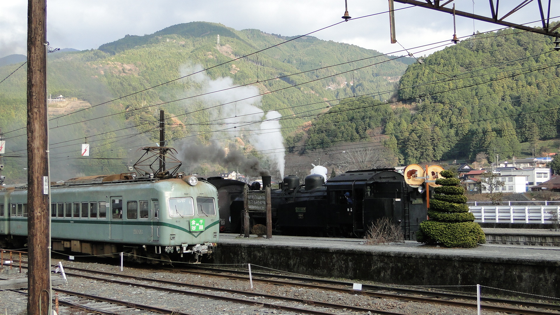
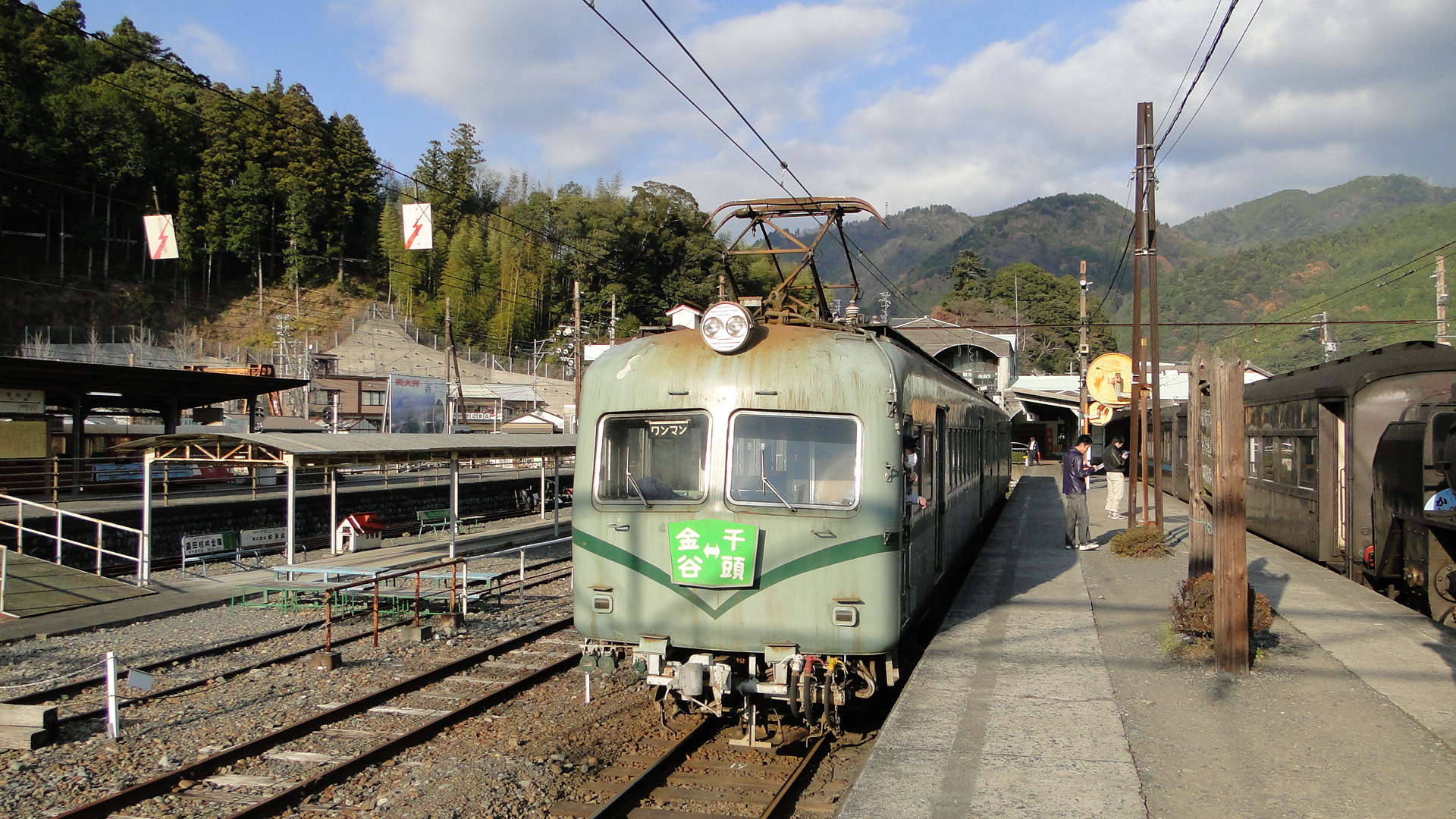
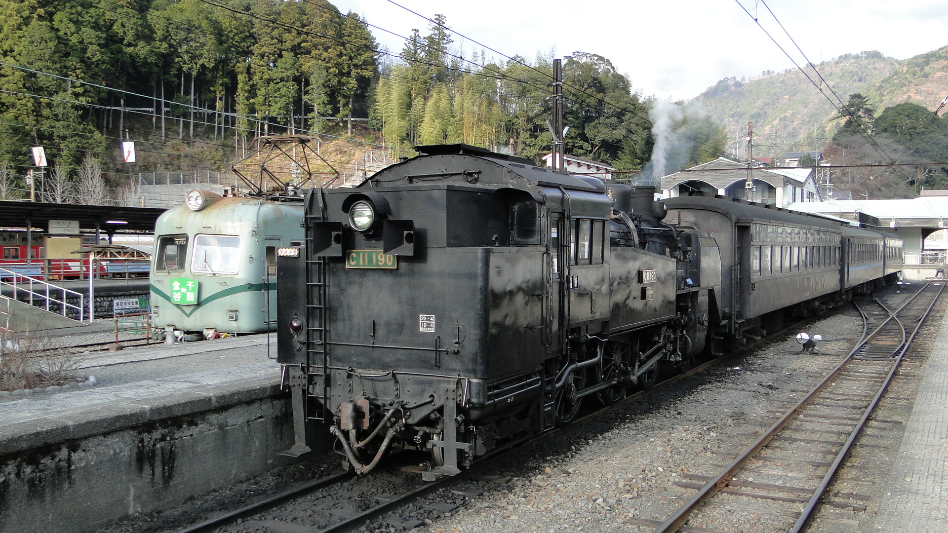
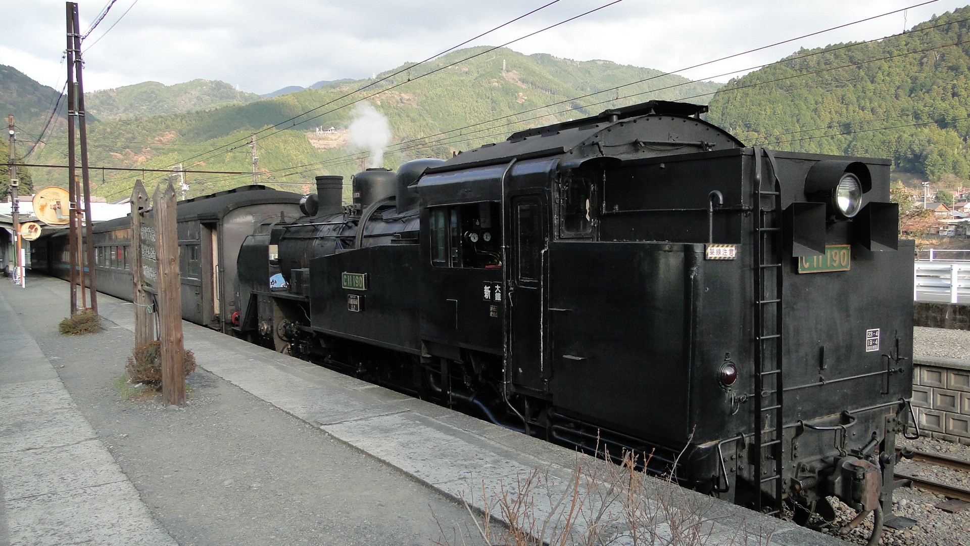
The highlights were the workmen at the start pushing a rail ladder along, the manual operation of the turntable and the in-car entertainment on the way back!
I'll be returning again...
Minamisenju and Aizuwakamatsu
I've recently been though both of these places and thought I'd write a few quick notes on both.
Minamisenju
This is an area of Tokyo known to be a bit of a ghetto...
Here you'll find a lot of down and out souls wandering, drinking and sleeping in the streets. It is a real eye-opener and really brings a different feeling to Tokyo. There are 2 youth hostels here; I stayed at the Aizuya Inn.
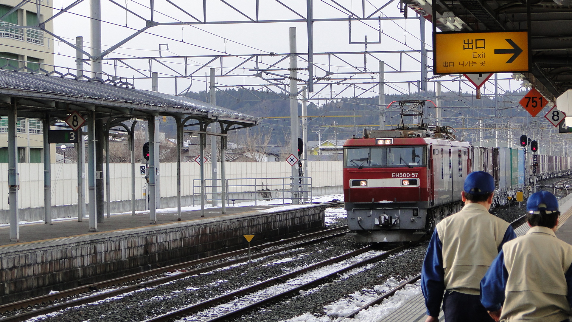
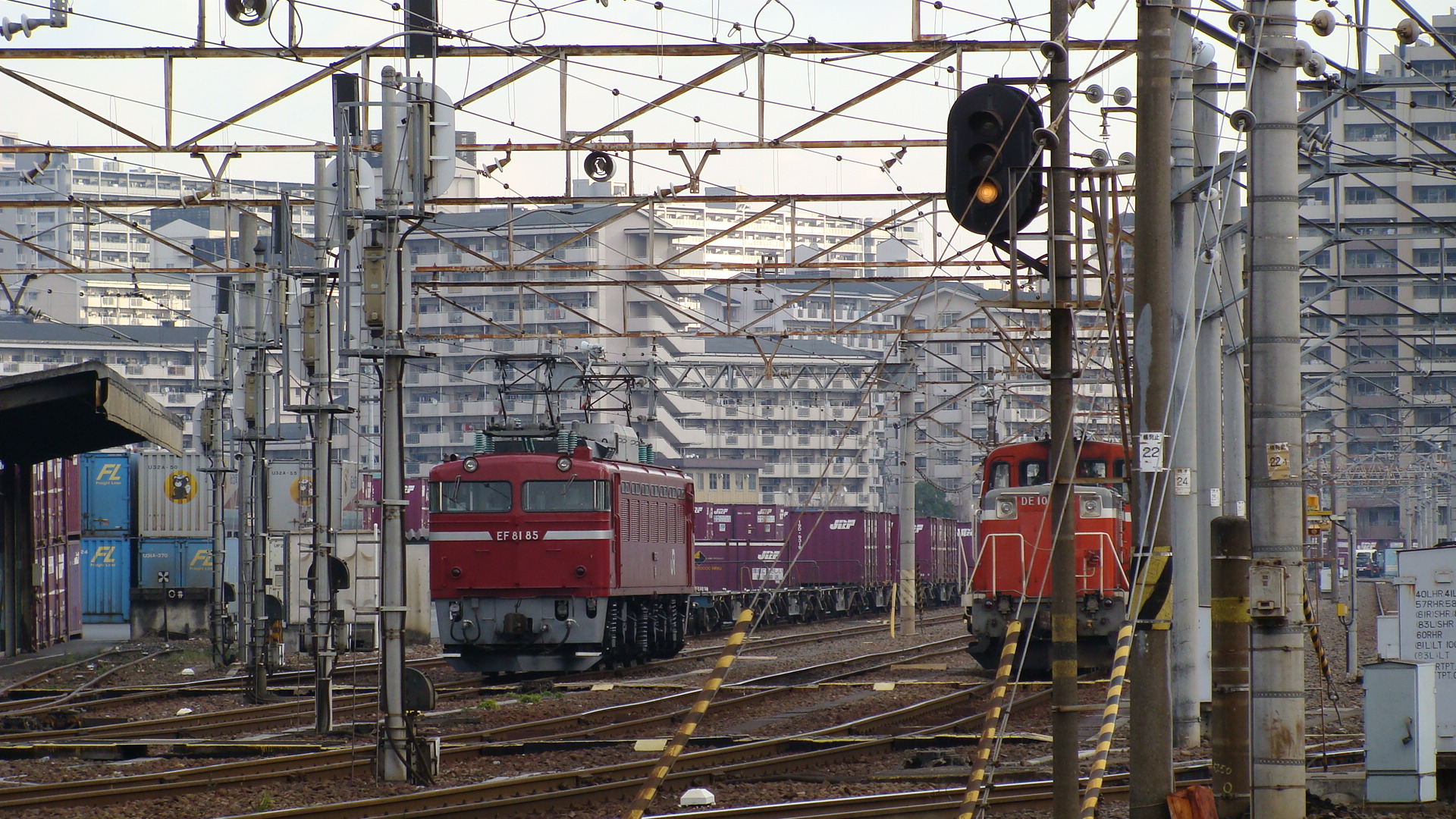
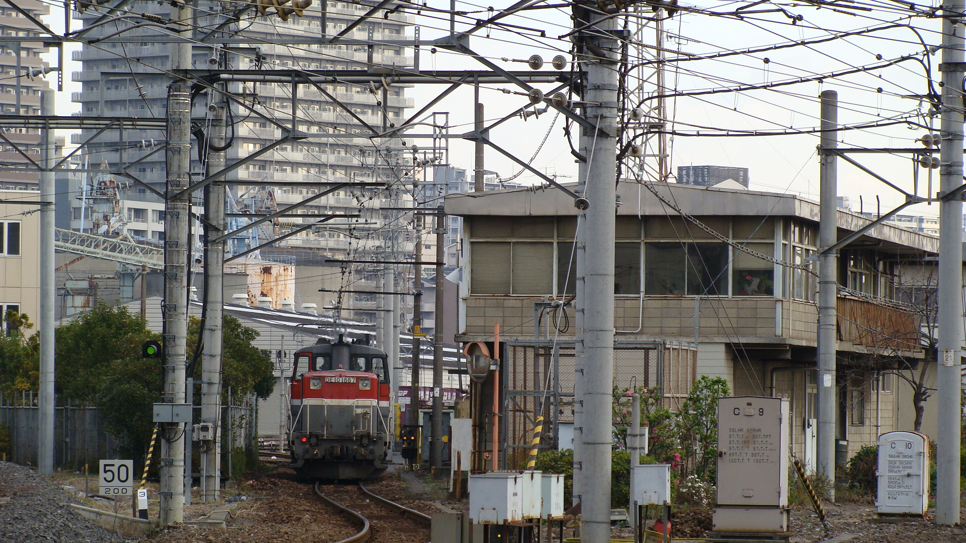
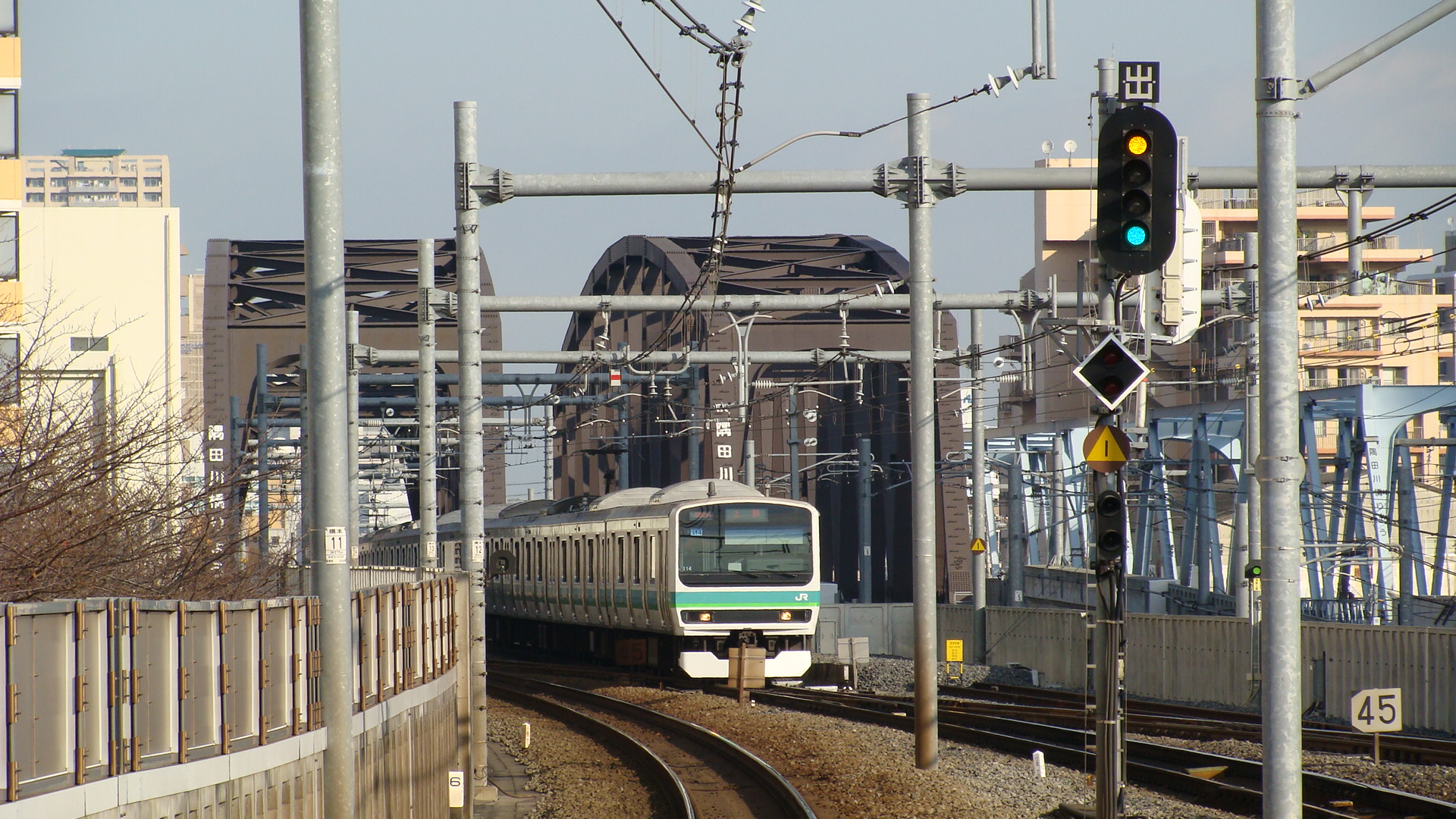
Now, the great thing about this place is that JR East has a nice freight station (Sumidagawa Station Container Terminal) that acts as a transfer point for freight up the east-coast line. Upon first arriving to the passenger station (On the Joban Line, 2 stations off the Yamanote Line) you must cross a pedestrian bridge south to get to the hostel. This bridge passes the entrance to the freight yards and the east-bound freight line.
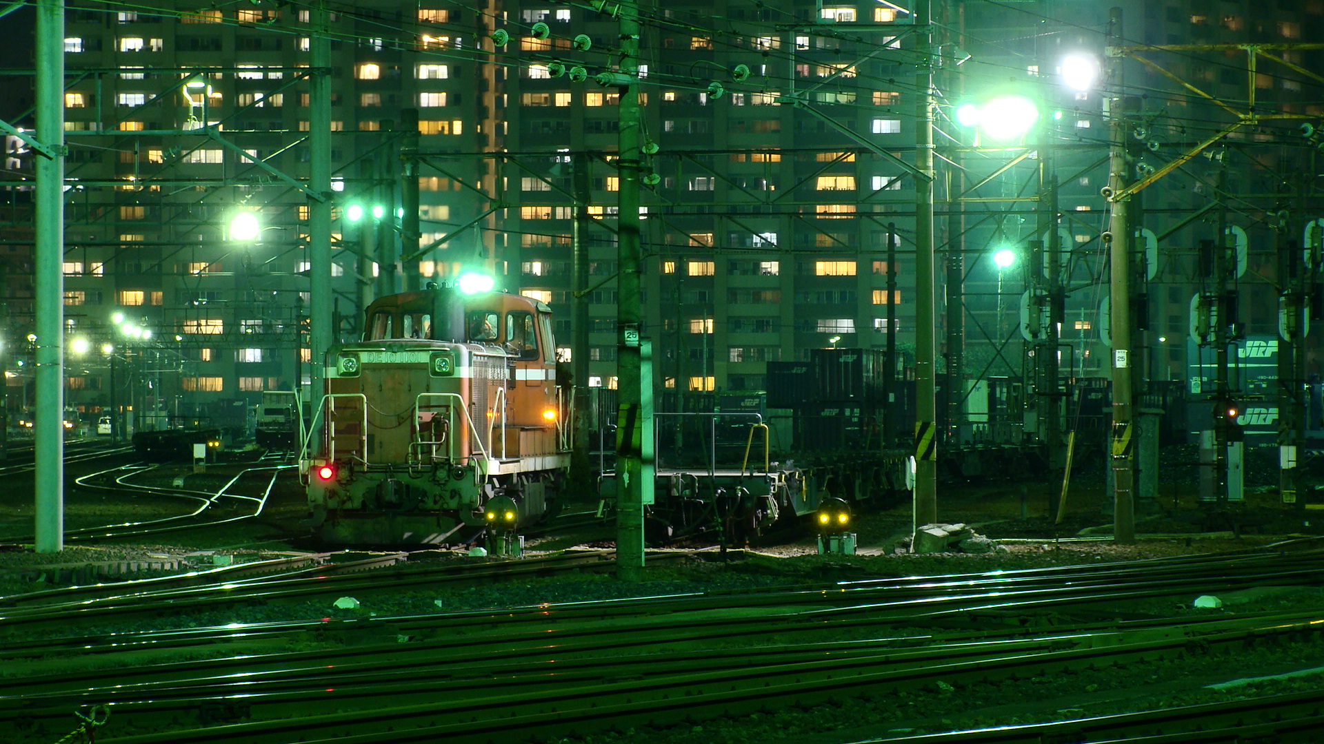
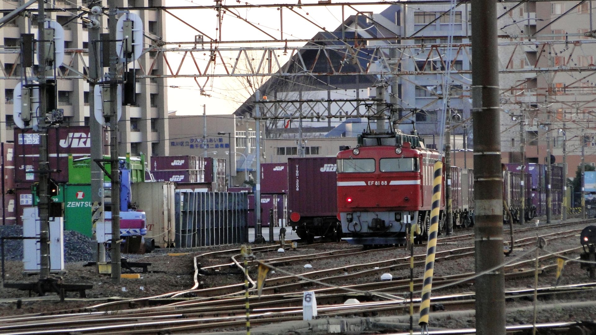
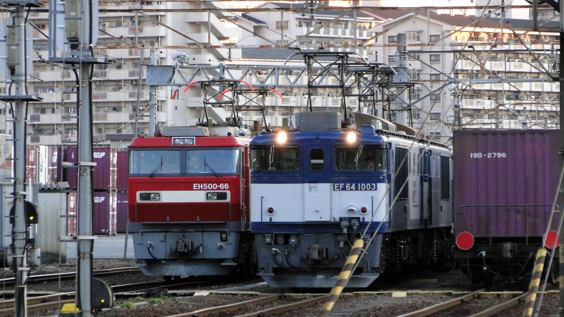
The yard becomes very active at night and quietens during the day. You will find freight trains coming in from both directions, but the best are those heading towards Tokyo, as they will pull past the yard and then reverse in. There are a few DE10 shunters and usual stabled EF81s and smaller electric locomotives. I stayed back one night until it got too cold and saw at least 5 freight trains enter to form at least 2 that then left. Freight seems to be sorted and then longer trains formed. This provides for still shots when the locos are paused to change direction and you have quite a few vantage points along the fence.
Some photos:
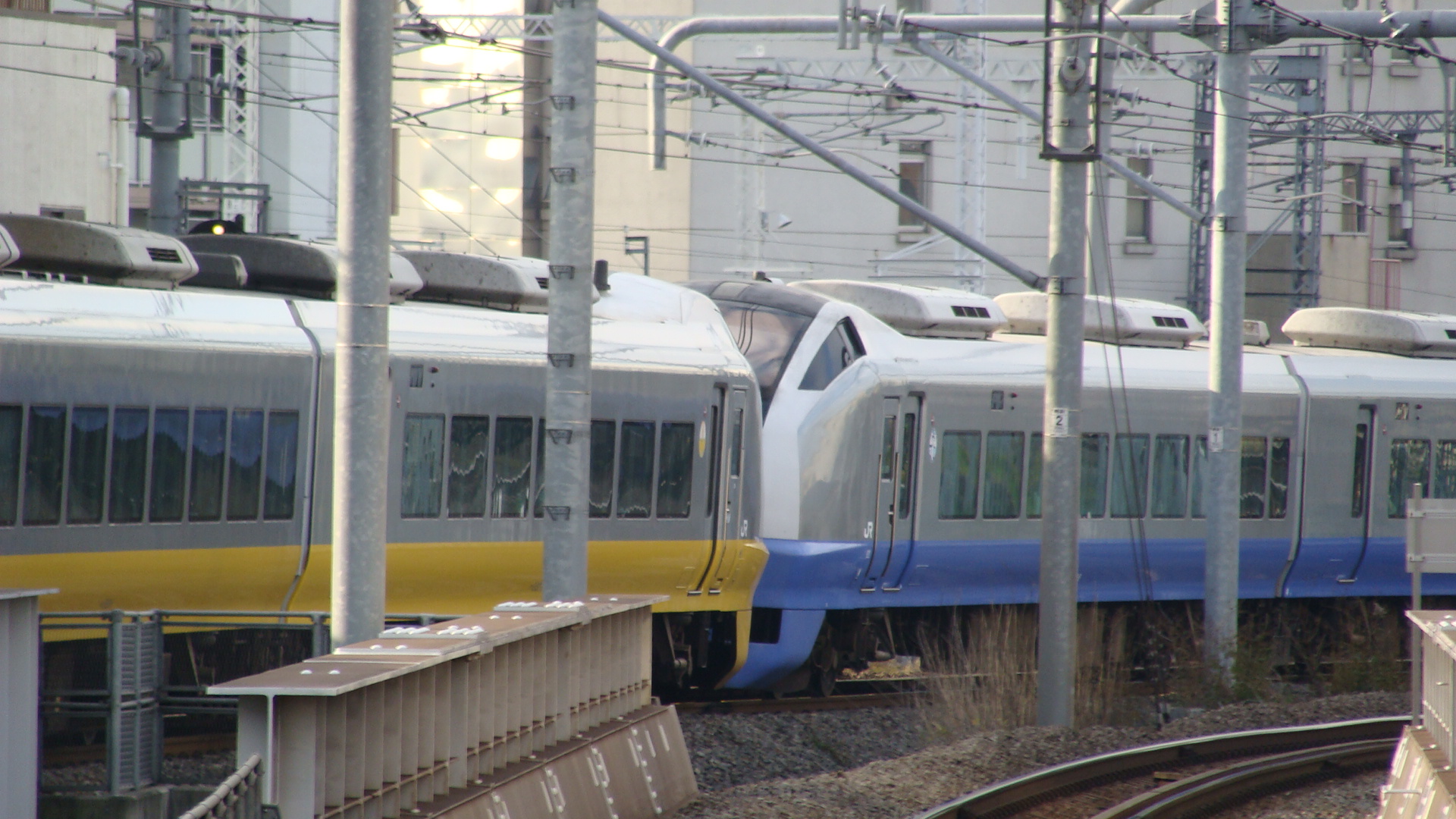
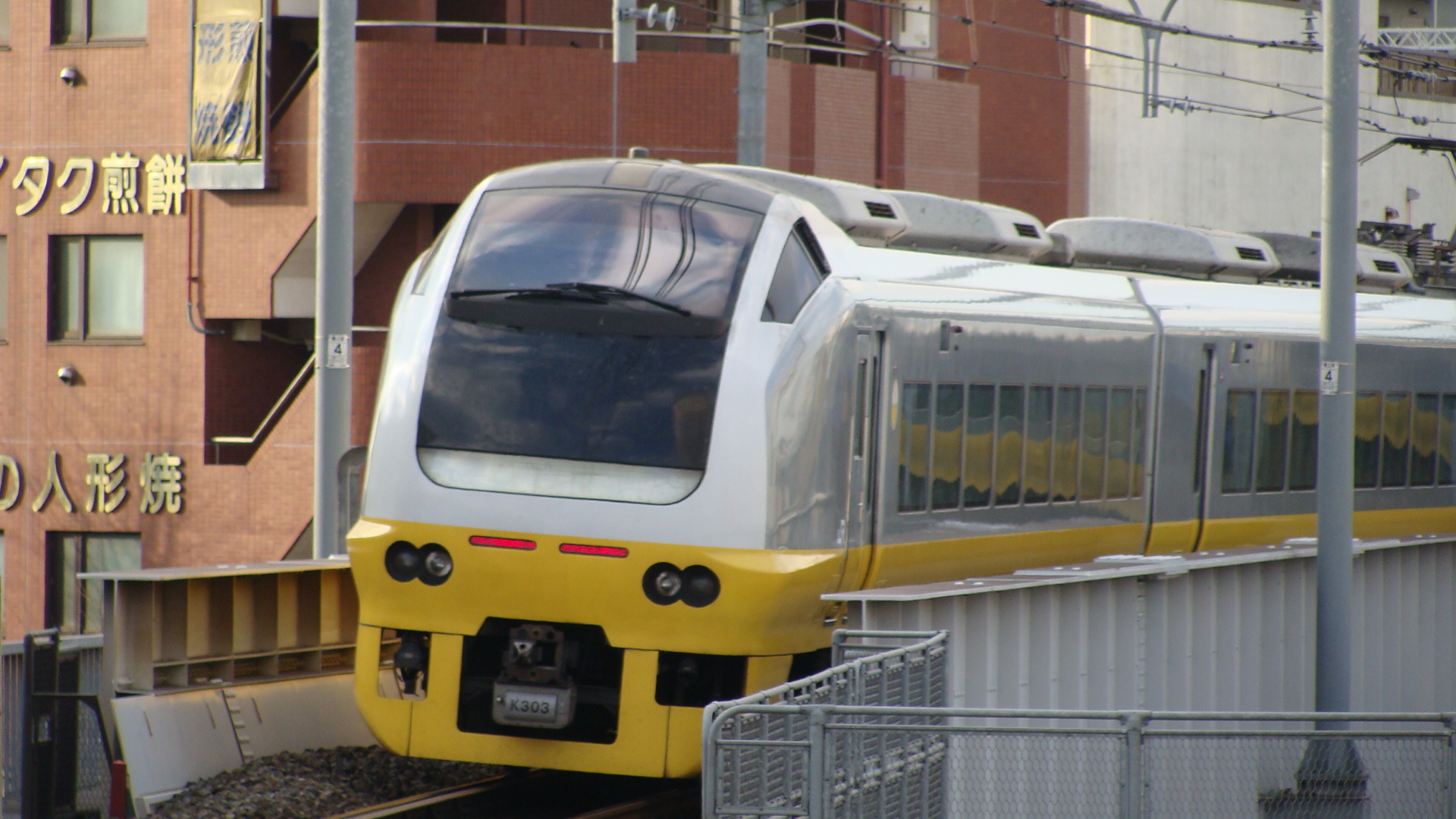
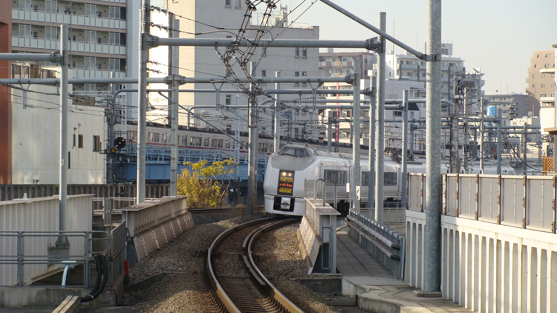
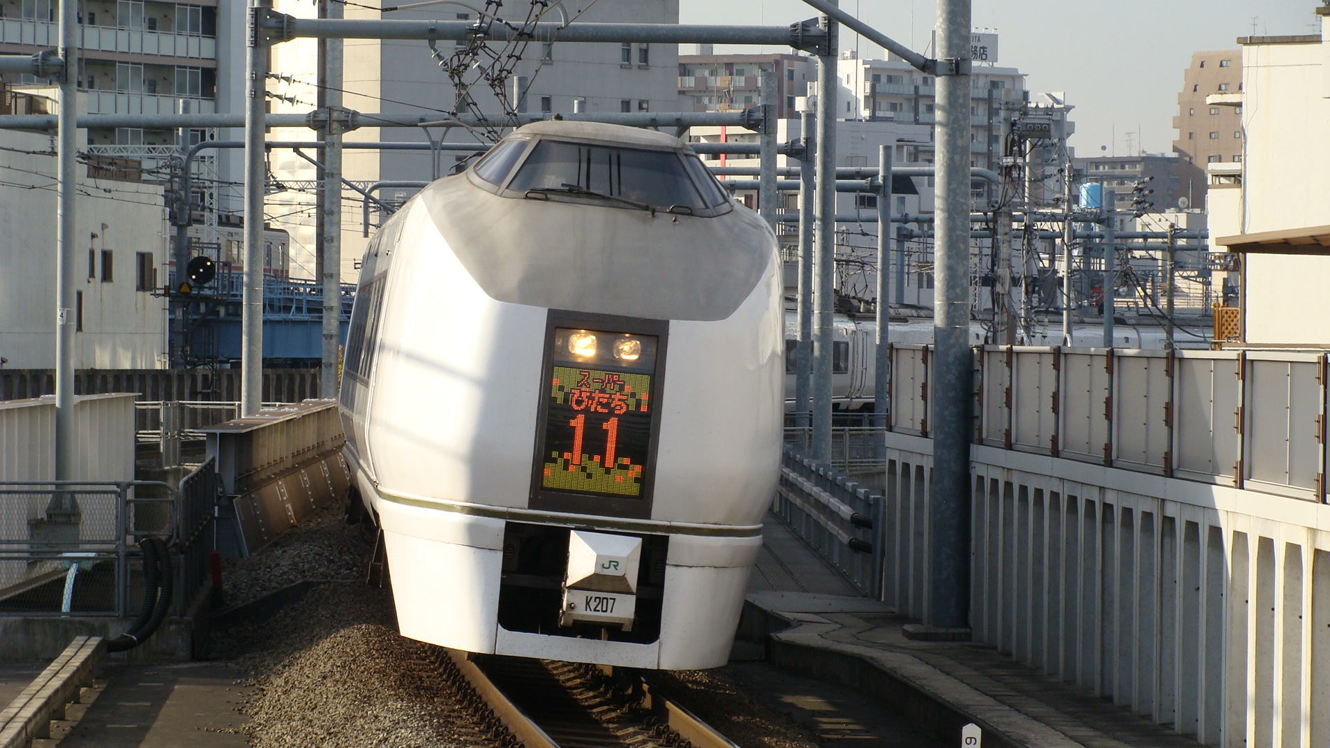
Also, the passenger station has the Ltd Exp. Hitachi services shooting through:
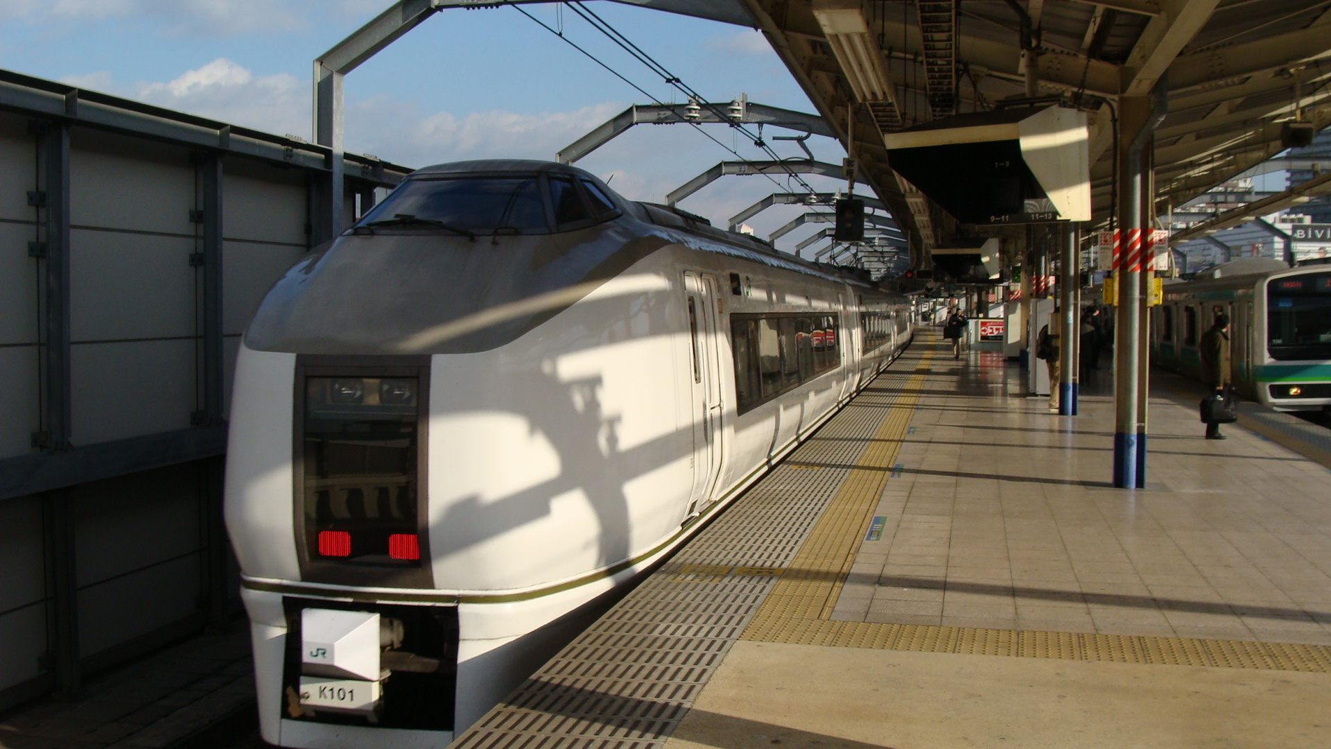
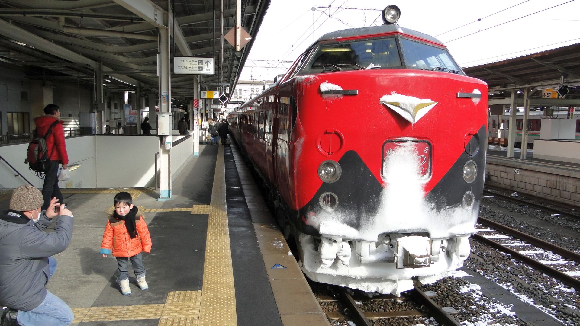
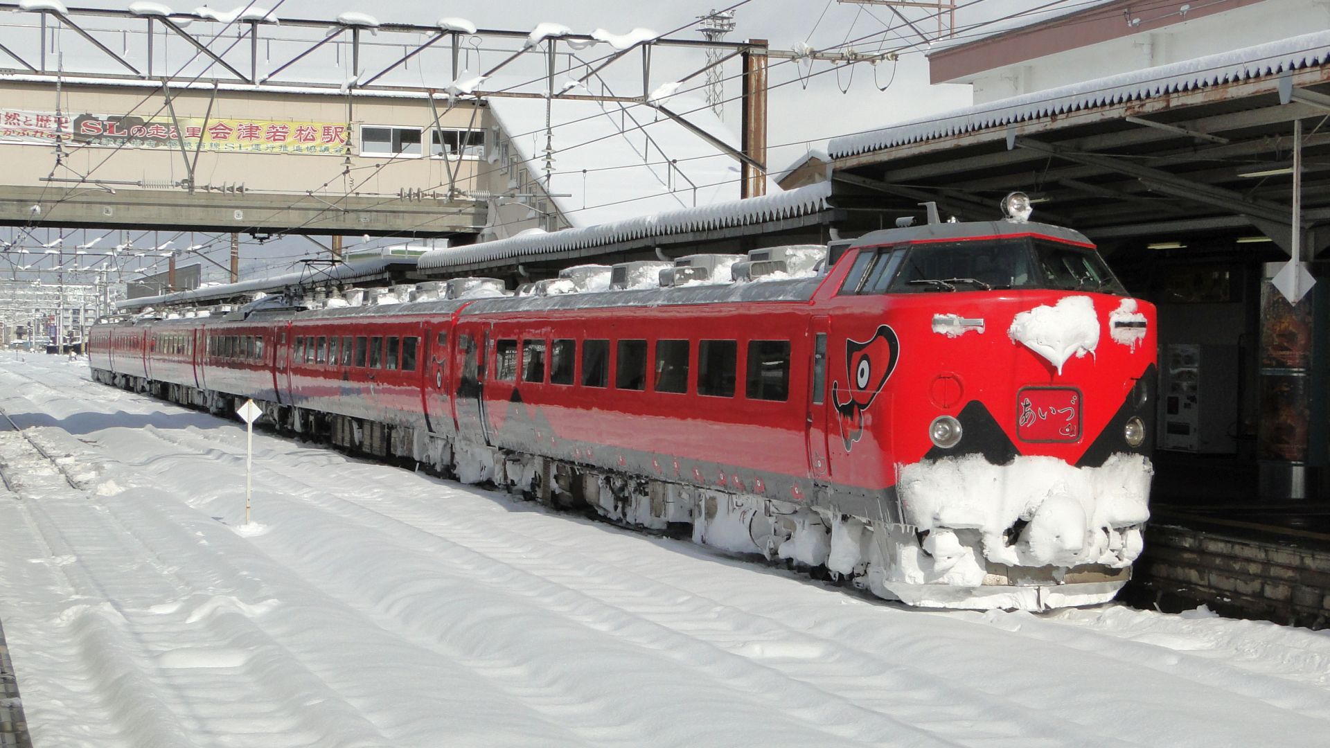
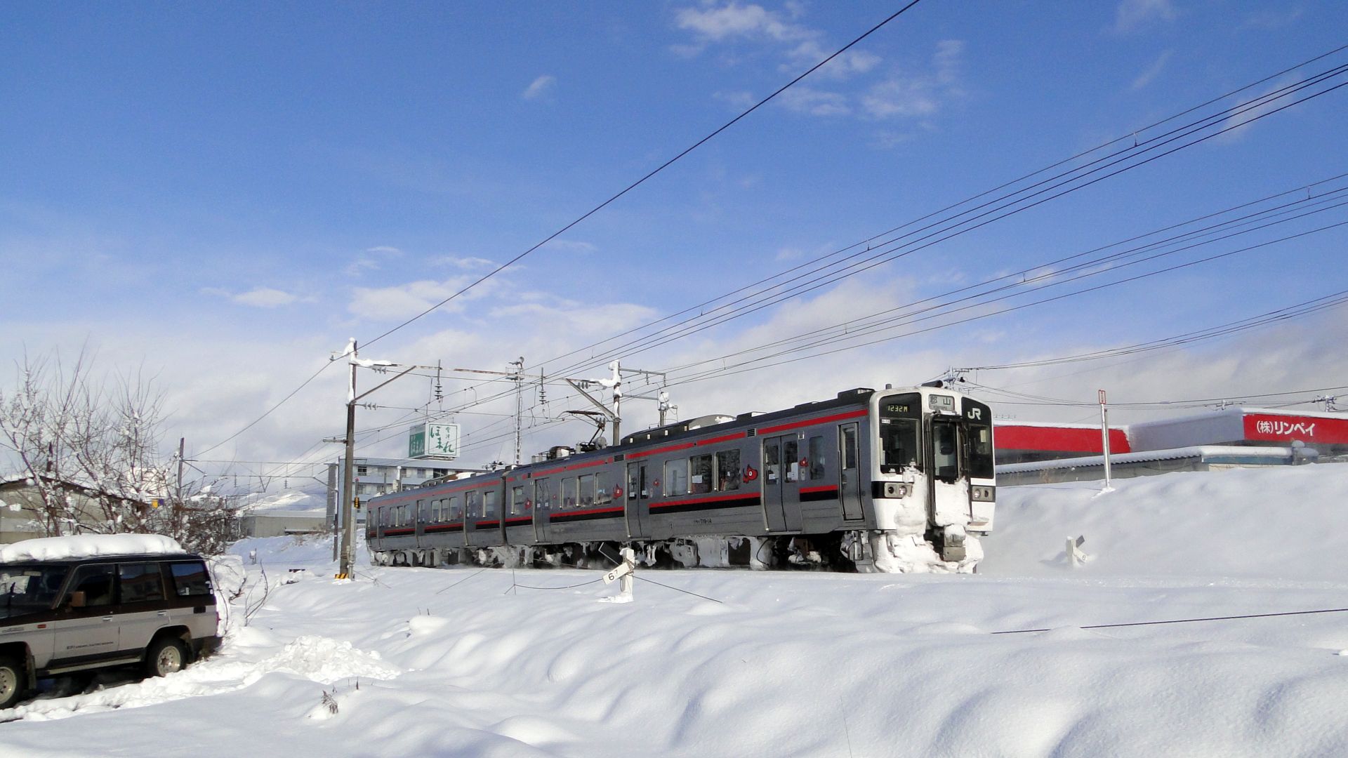
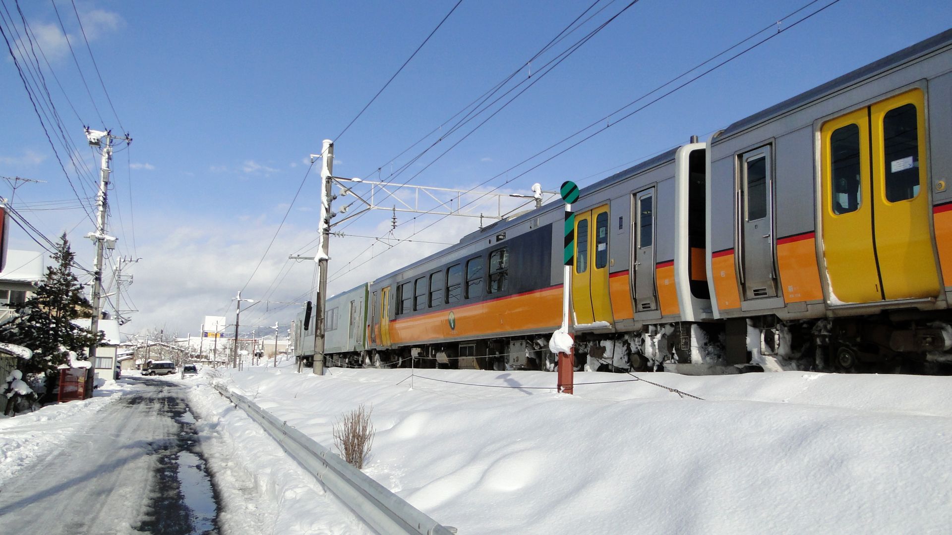
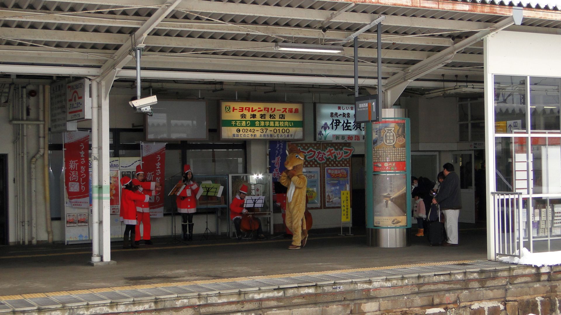
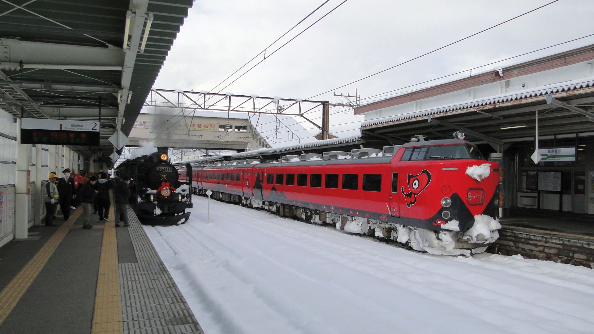
Aizuwakamatsu
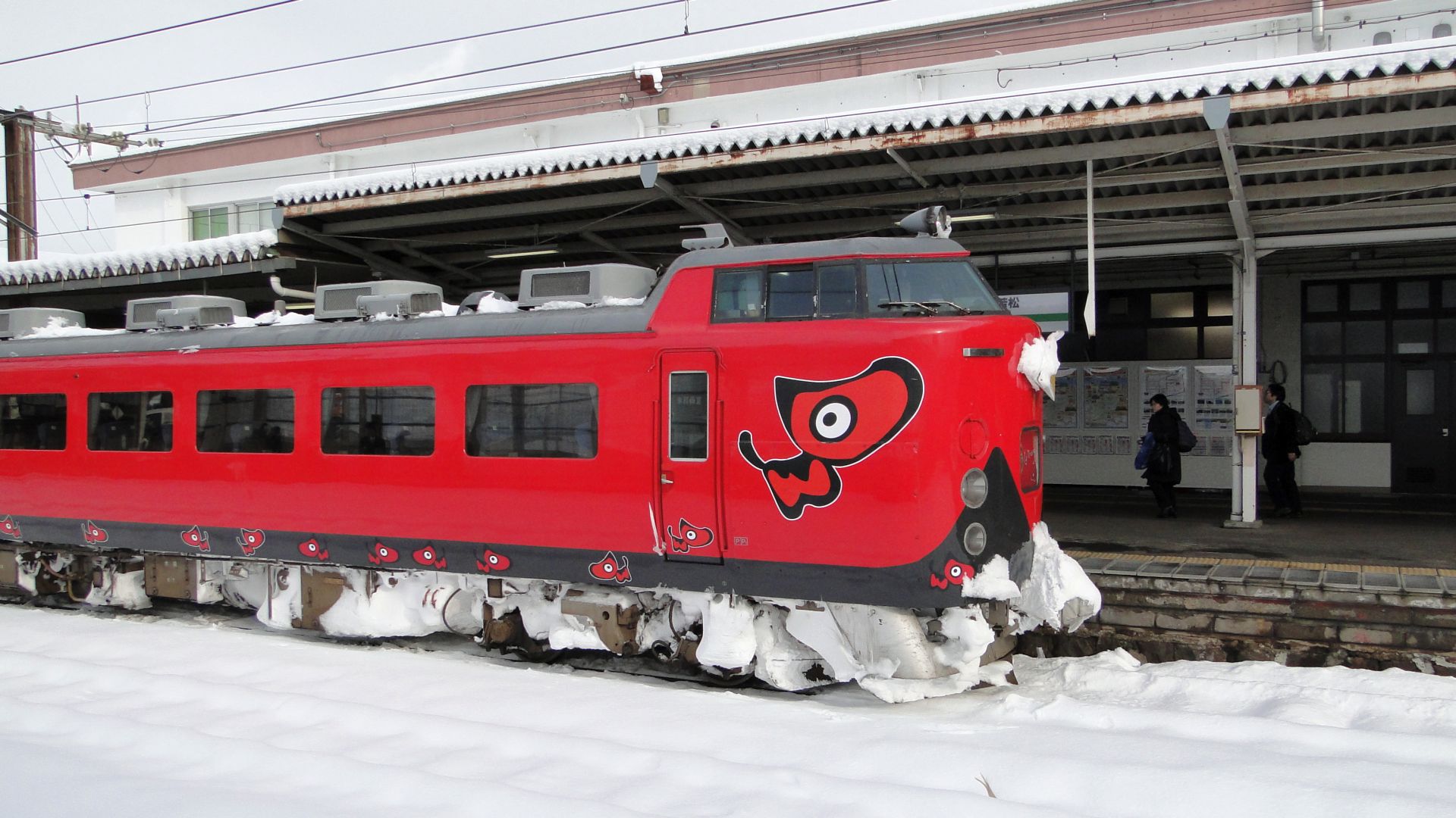
Following the plan in the previous post, I took a Bullet train from Tokyo to Koriyama and then the Aizu Liner 1 from Koriyama to Aizuwakamatsu. The plan was then to catch the local train to Shiokawa to get a shot of the SL Banetsu, but the connection wasn't made as the Aizu Liner 1 was about 4 minutes late and that meant there wasn't enough time to put luggage away in lockers.
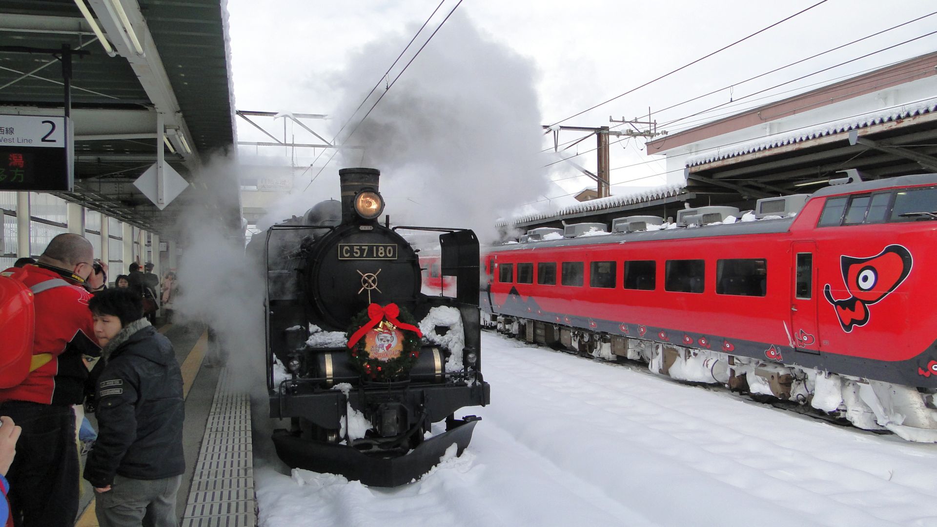
Fortunately this paid off, as the SL was to arrive at 1331 and I was to then catch the return Aizu Liner to Koriyama at 1414. The SL didn't show up until 1404 and that left very little time to get photos.
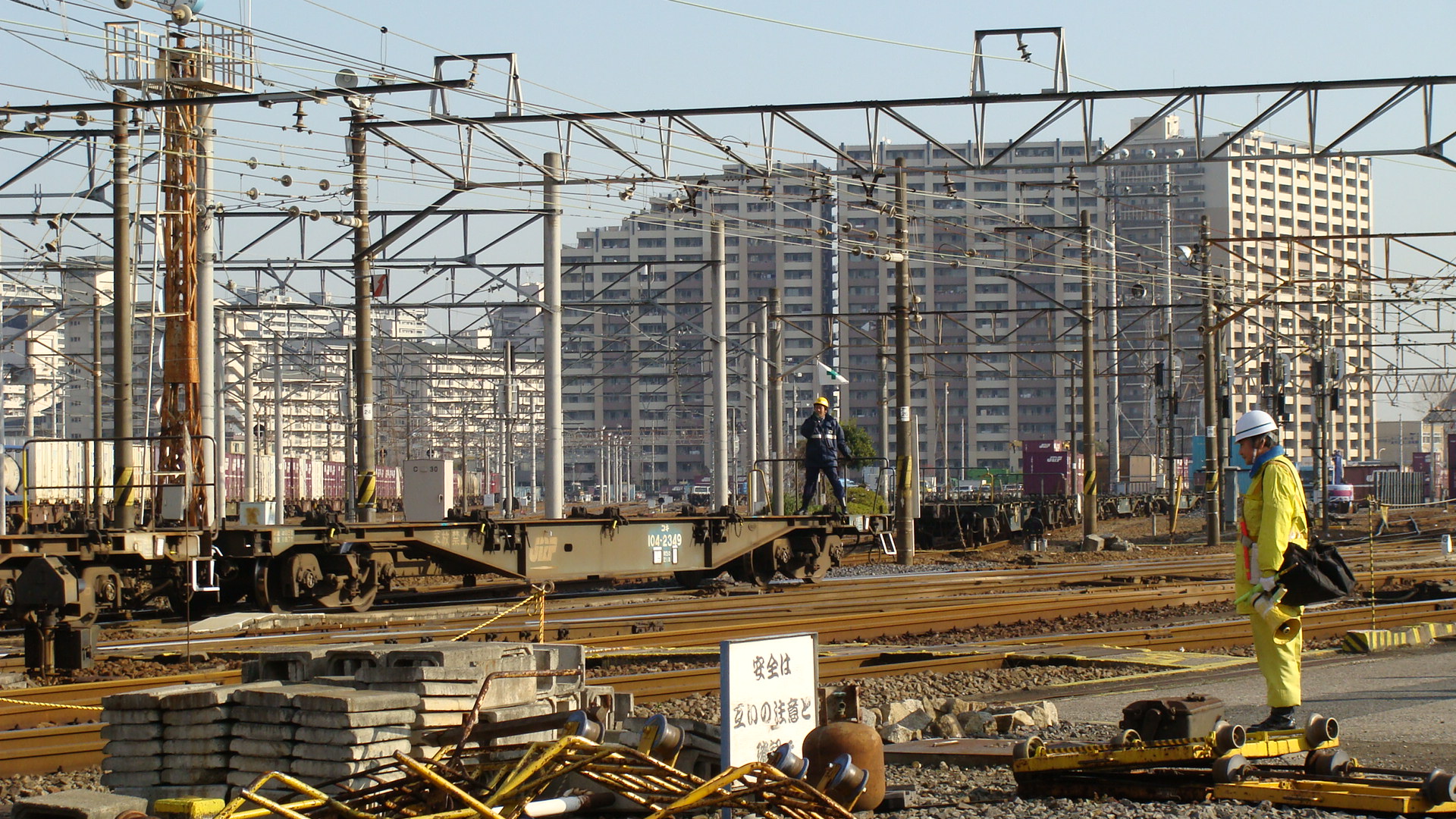
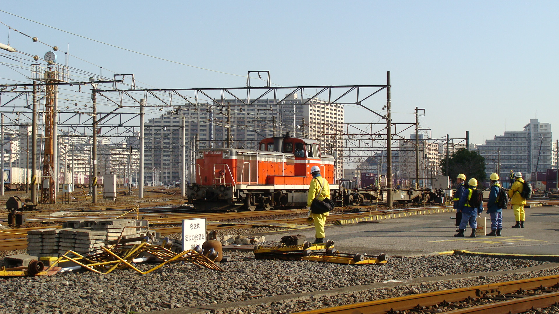
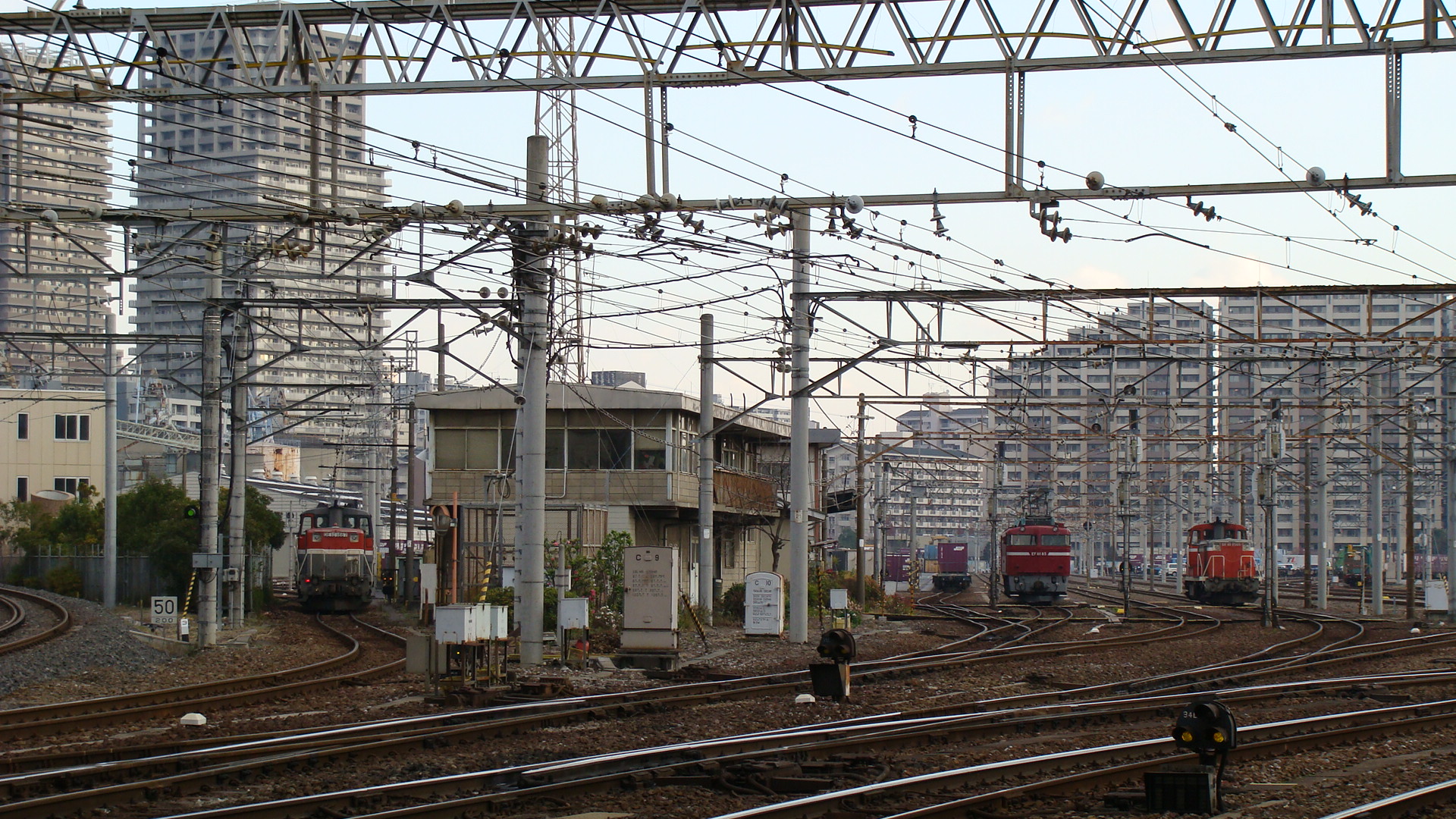
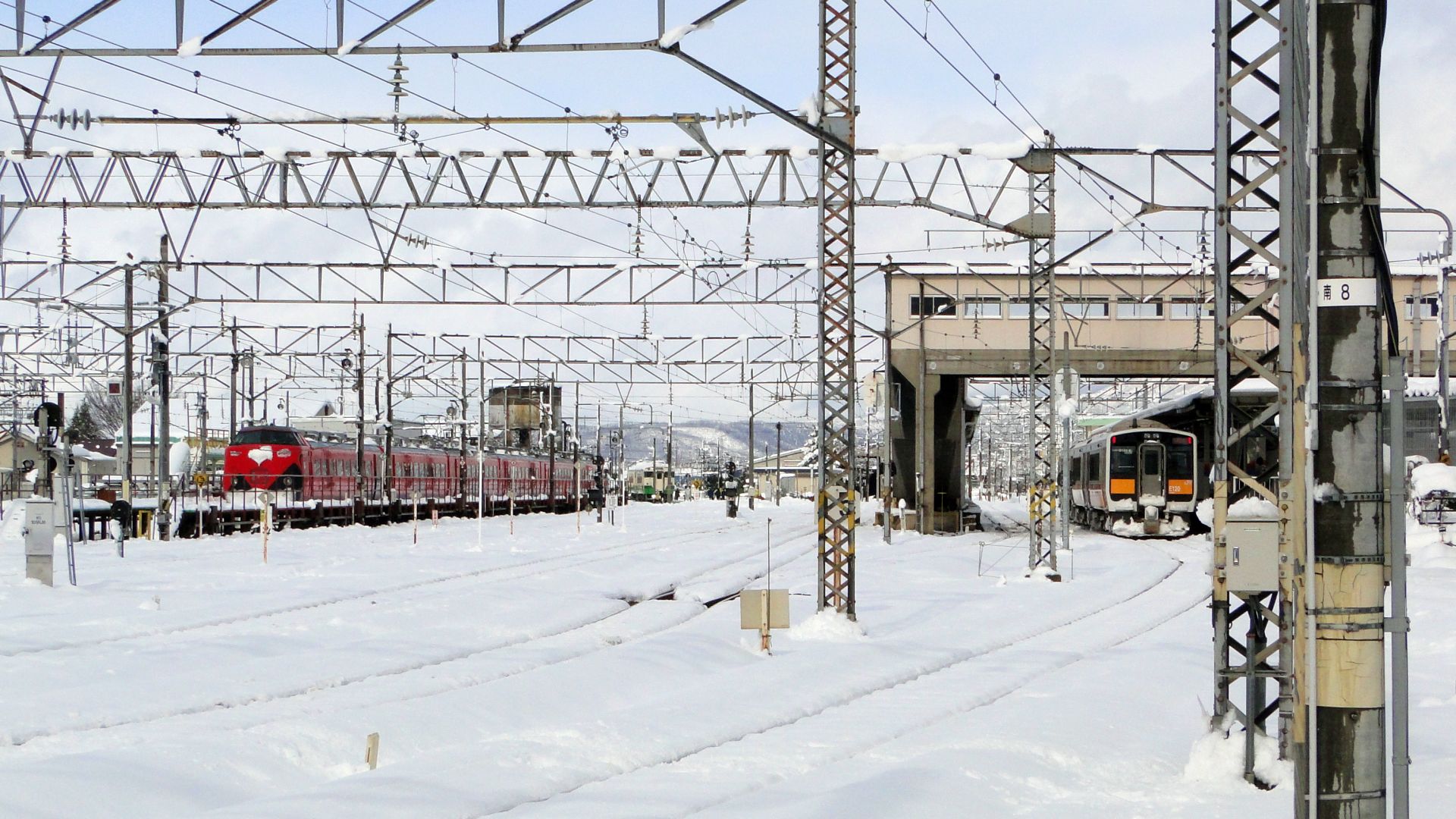
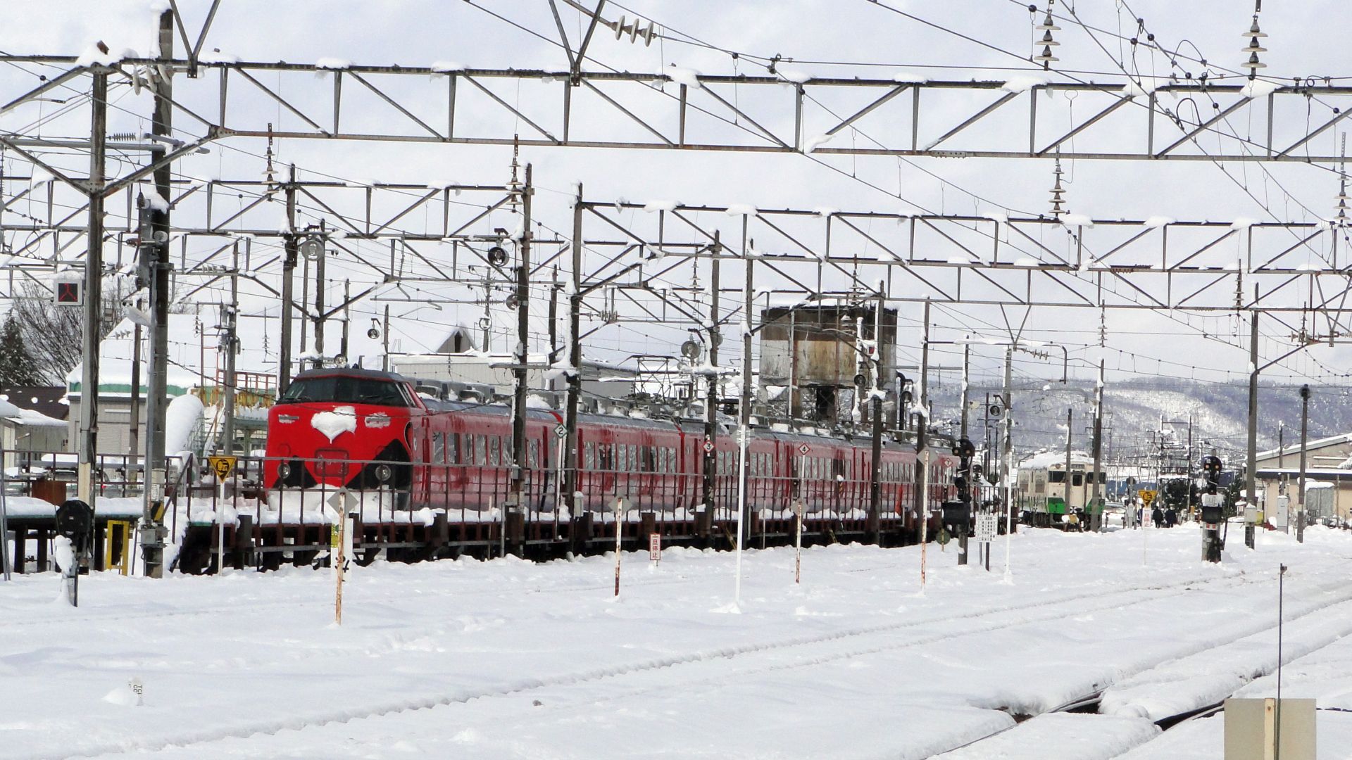
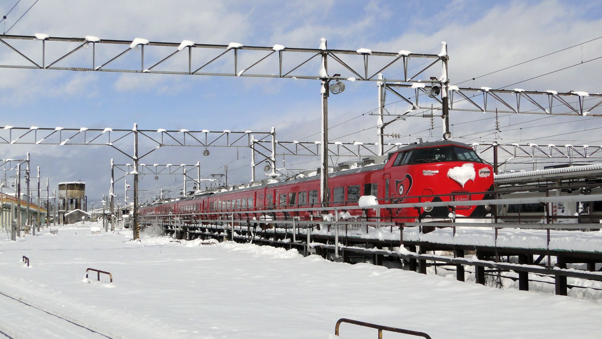
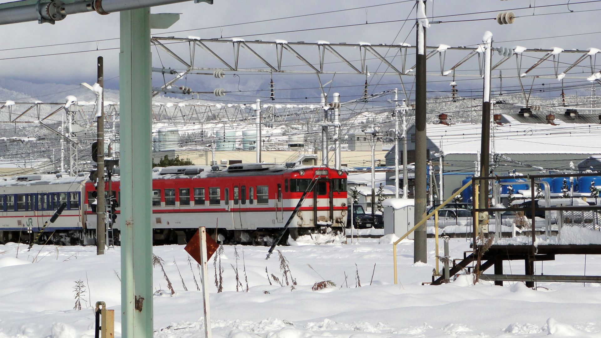
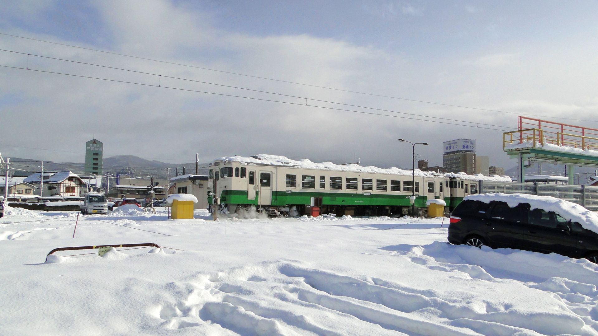
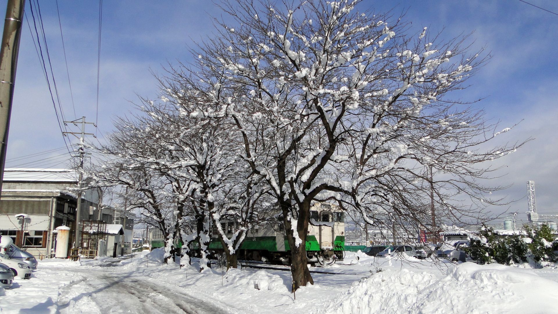
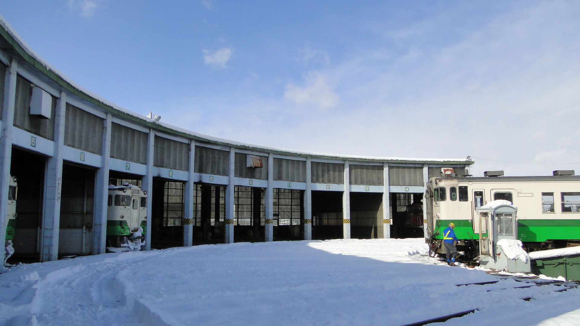
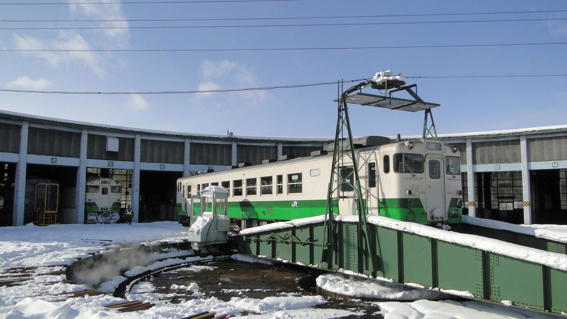
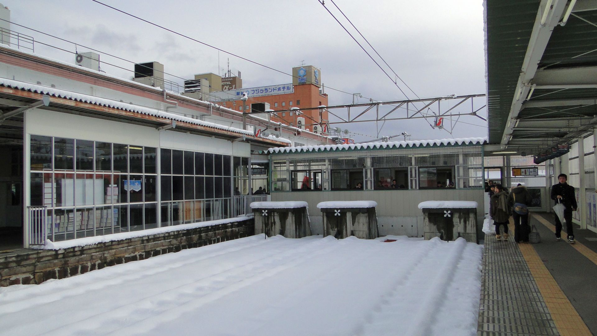
Since I arrived at Aizuwakamatsu juse after 12pm, I then had an hour to loiter and wait for the SL to arrive. I wandered around the station and found a few locals walking a track through the yards, it seemed harmless enough... this turned out to be an amazing walk through the inner workings of the DMU service area (see the photos below.) The snow made it even more perfect.
I made it to a good spot near a pedestrian underpass and waited for the SL. I was about 20mins walk from the station and knew I had to run as the Aizu Liner wasn't going to wait for me. From where I was I saw the Liner pull out of staging and head into the station and I knew I was running out of time. I went back to the station, put my luggage in the Aizu Liner and then the steamer arrived.... took photos... and then went north.
Here's the shots from the day... it's welll worth staying longer:
Japanese Level Crossing Lights
After seeing how small surface-mount LEDs have gotten, and how cheap, I decided I'd grab a few from our local Jaycar Electronics Store and build a Japanese level crossing signal/light.
Ingredients
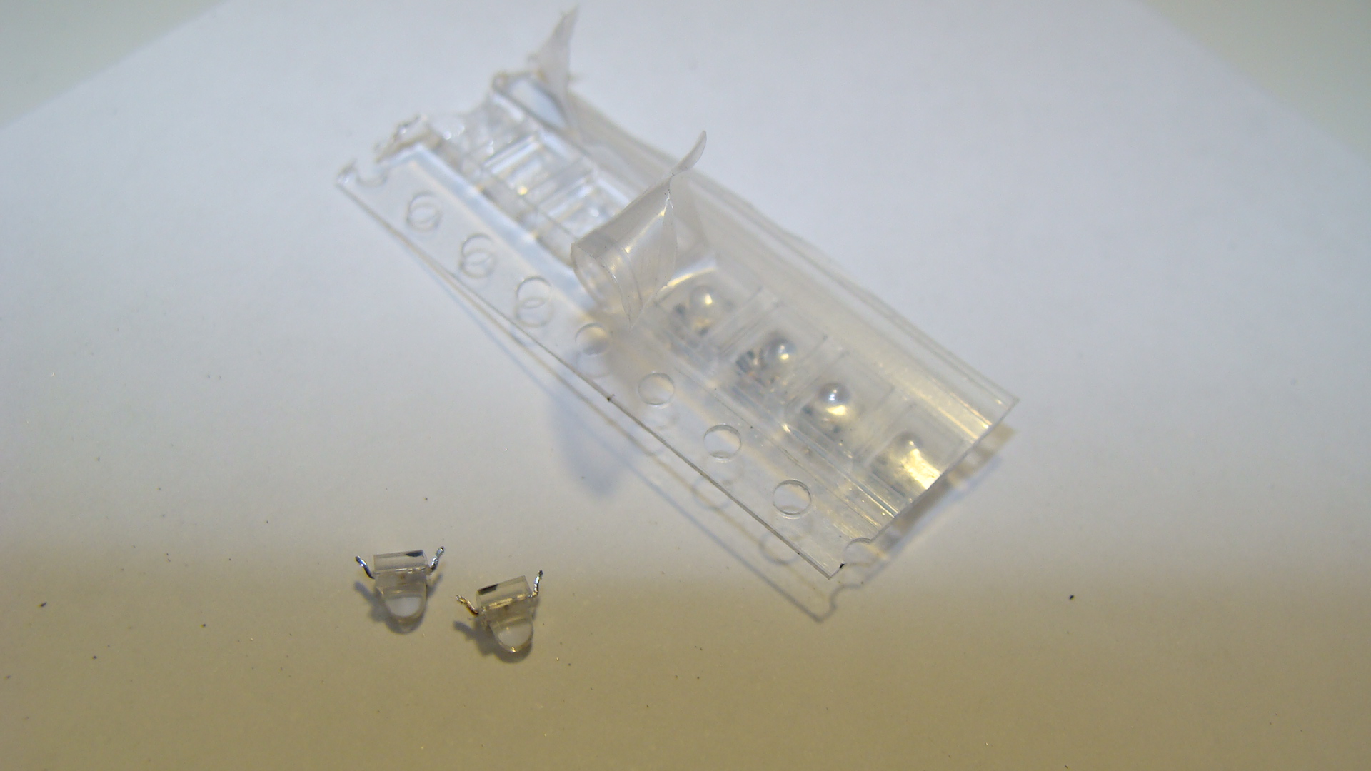
- Red SMD LEDs
- Metal tubing, hollow, for the main pole. I used brass from the local hobby store.
- Copper 'winding' wire. Used since it's already insulated.
- Soldering equipment.
- Thin cardboard
The process
Firstly cut a length of the metal pole and then grind a hole in it behind the area where you intend on soldering the LEDs.
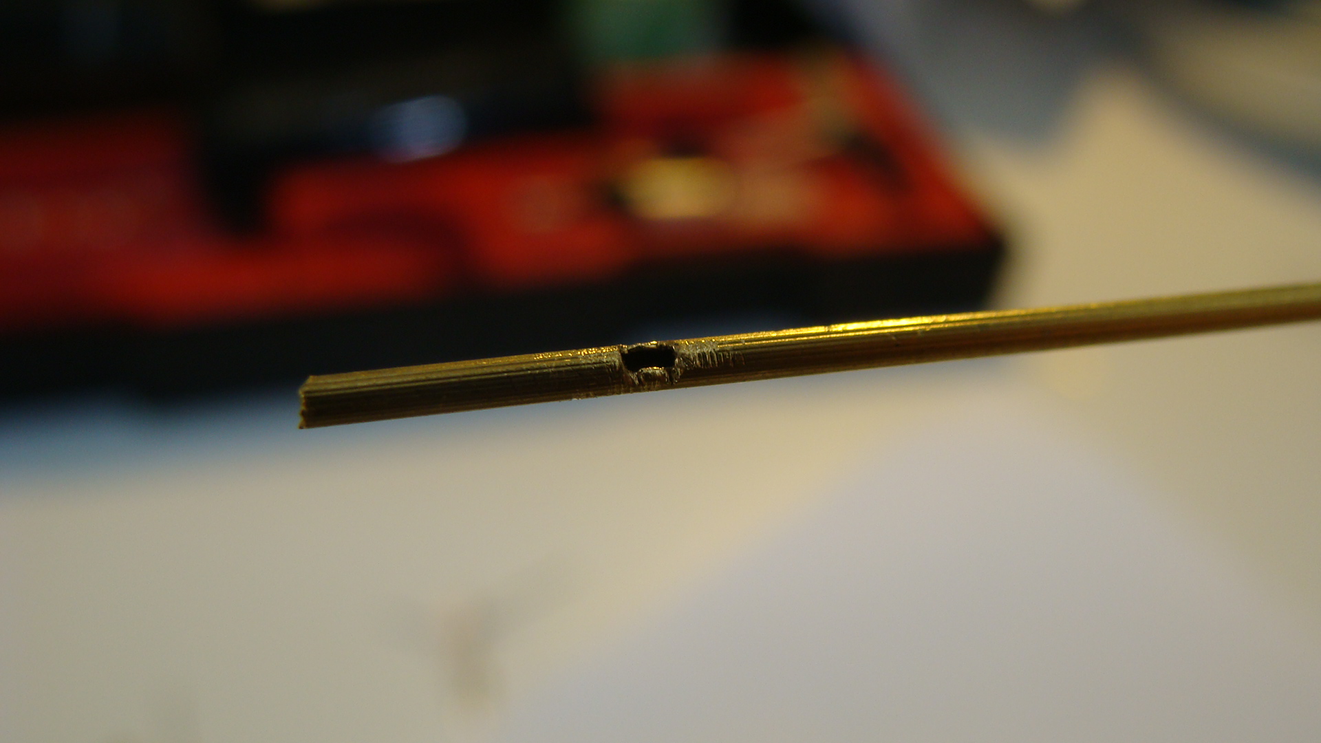
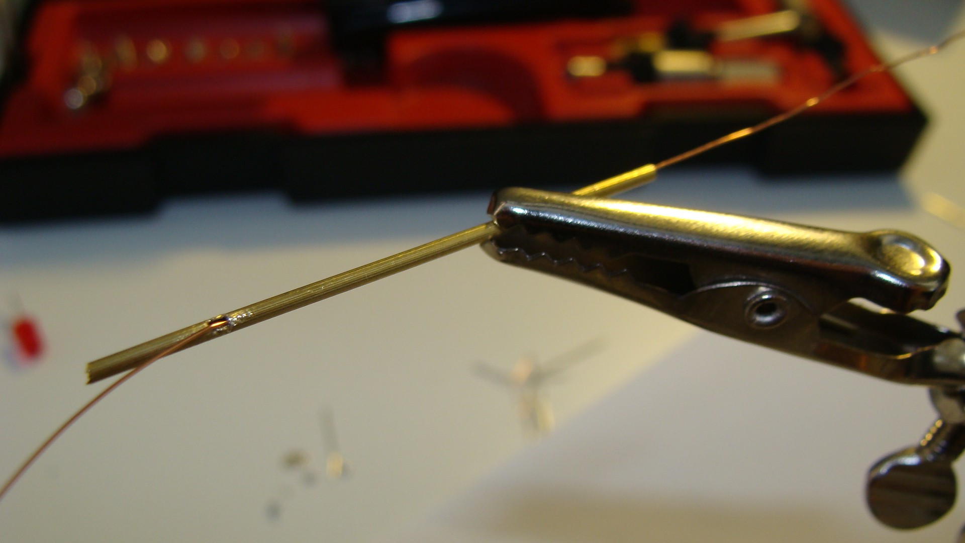
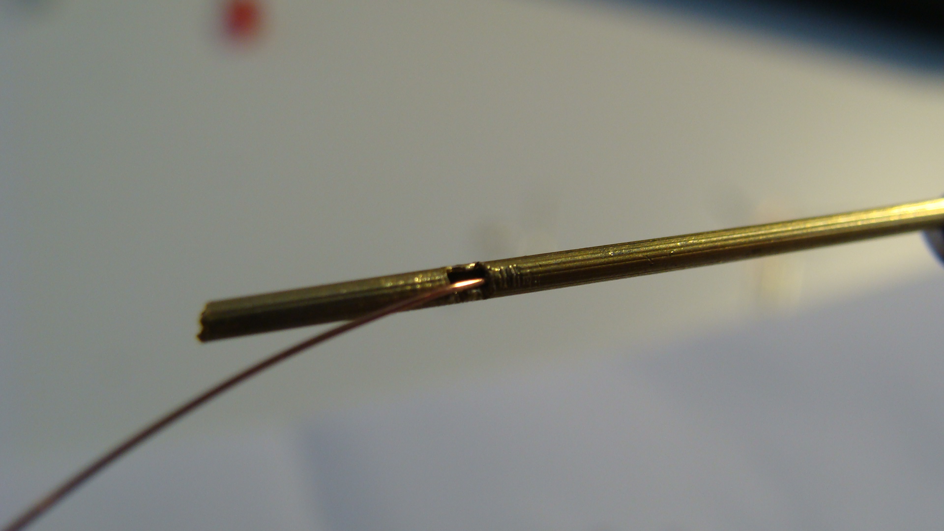
You can see I've run the copper wire through to make sure there are no obstructions. Be careful when doing this as you may well remove the insulation where the wire will rub on the metal pole.
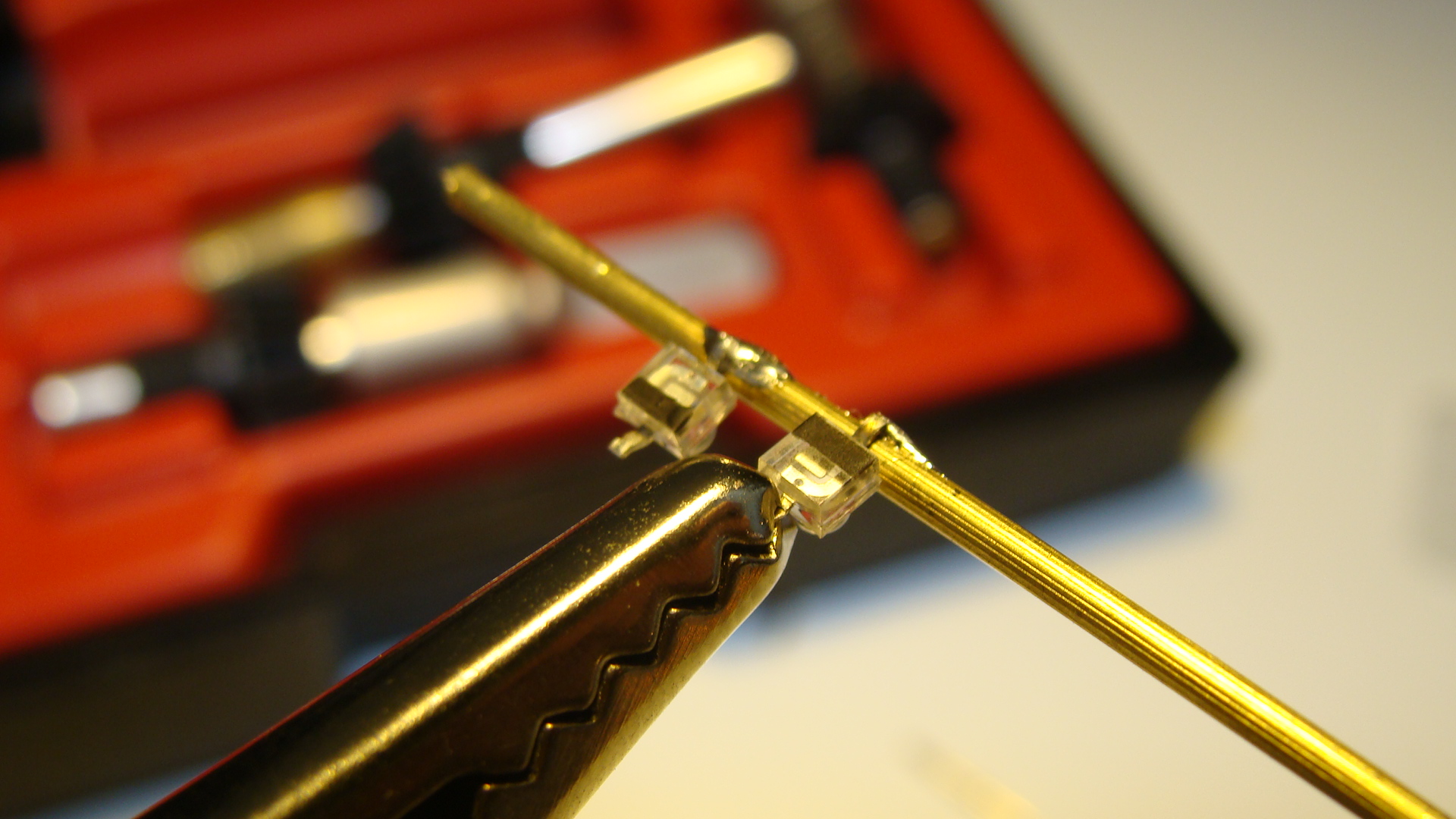
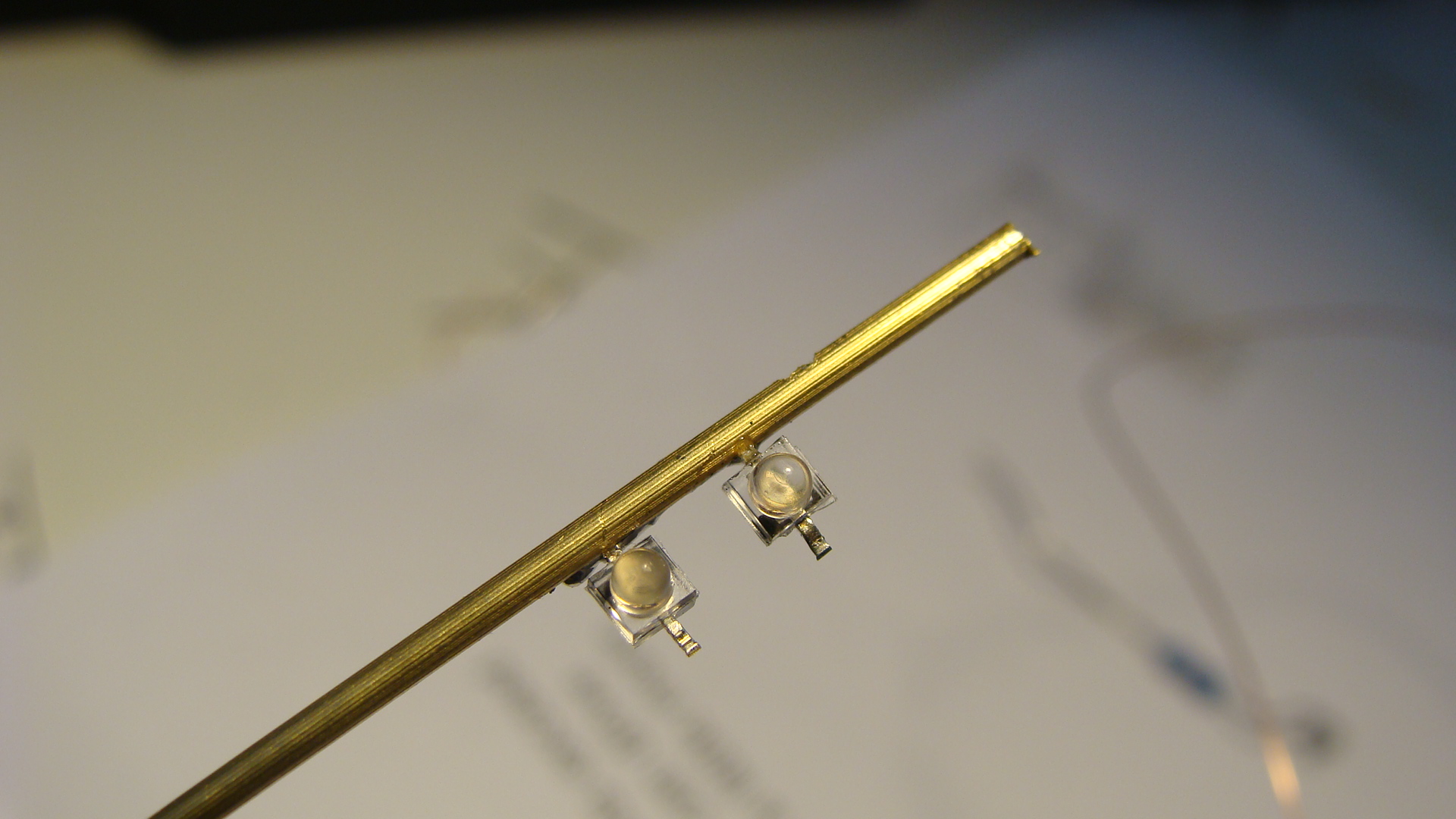
Next rotate the pole around and then solder the LEDs into place. Make sure that one LED is reverse polarity!
Also solder a wire to the base of the main pole.
Run the thin copper wire from the tabs on the LEDs into the hole and then out the bottom of the main pole. Do this after all soldering to avoid melting the insulation.
Cut some thin strips of cardboard and glue them as the cross above the lights.
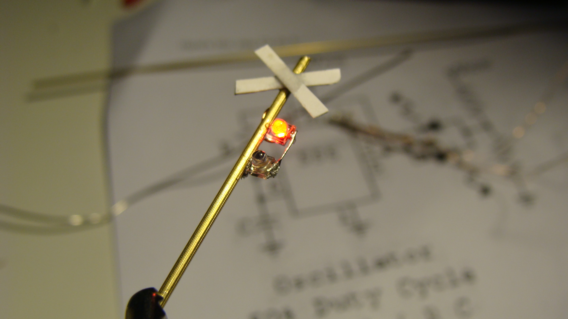
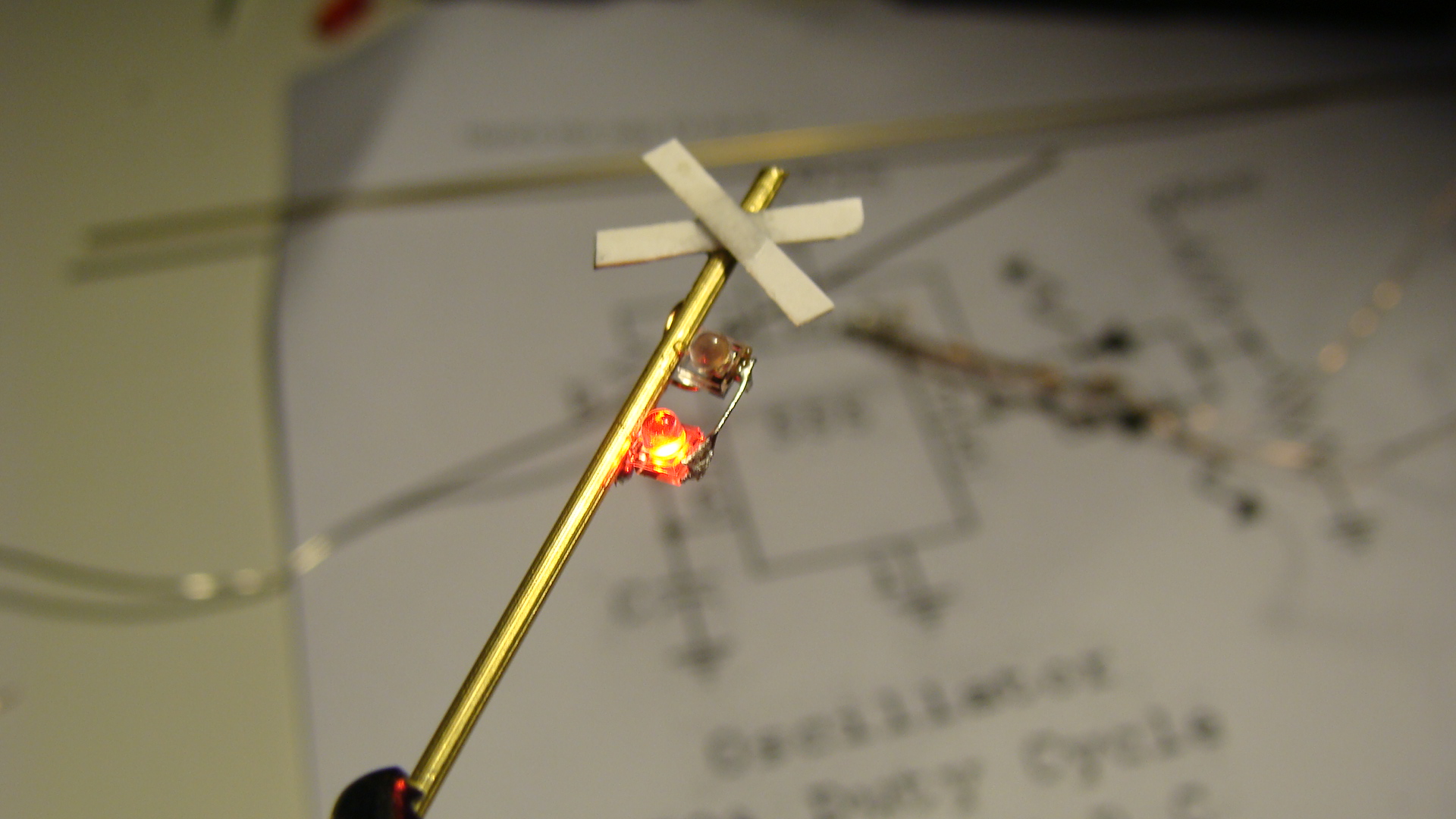
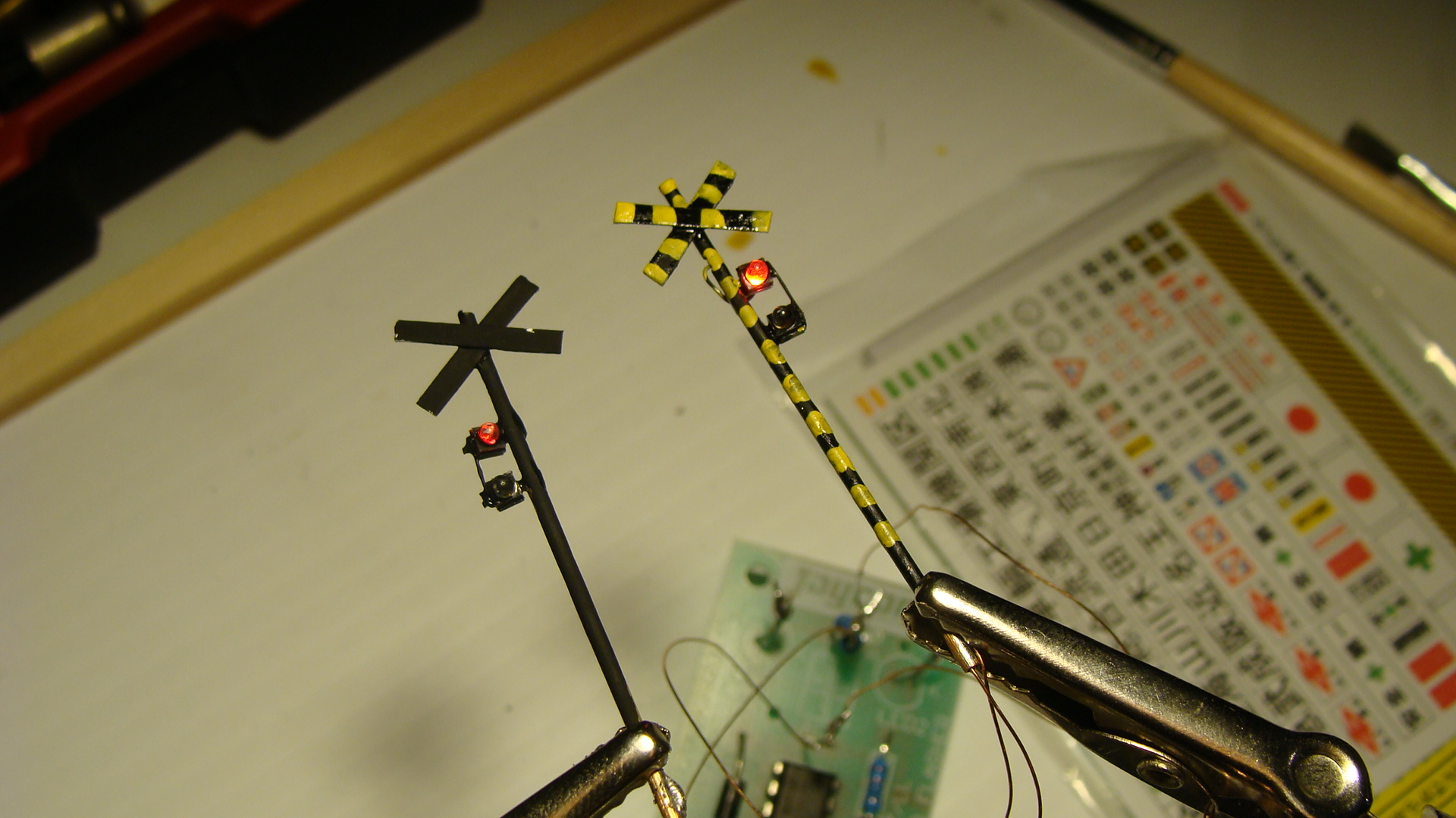
Apply some paint, I was a little sloppy.
The Circuit
Add your favourite flasher circuit.
Make sure that it swaps polarity to only have to use two wires.
And that's about it... Signals next...
SL Banetsu Monogatari (SLばんえつ物語)
Information
Link to Banetsu West Line on Wikipedia
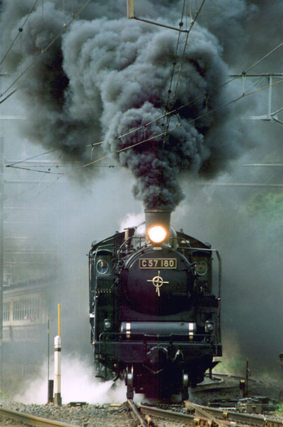
The West Banetsu Line (磐越西線 Ban'etsu-saisen) is a rail line in Japan operated by East Japan Railway Company (JR East). It runs from Kōriyama Station in Kōriyama in Fukushima Prefecture to Niitsu Station in Niigata Prefecture. The name "Banetsu" refers to the Meiji-era province of Iwaki (磐城) and the ancient province of Echigo (越後), which the East and West Lines together connect. "Sai" means "west" in Japanese.
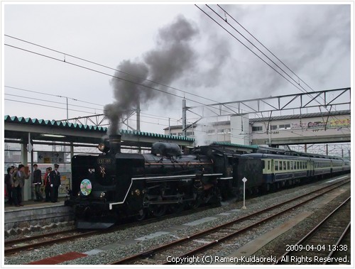
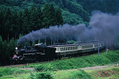
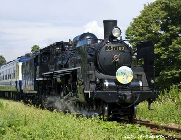
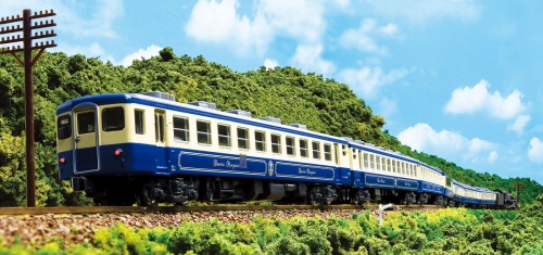
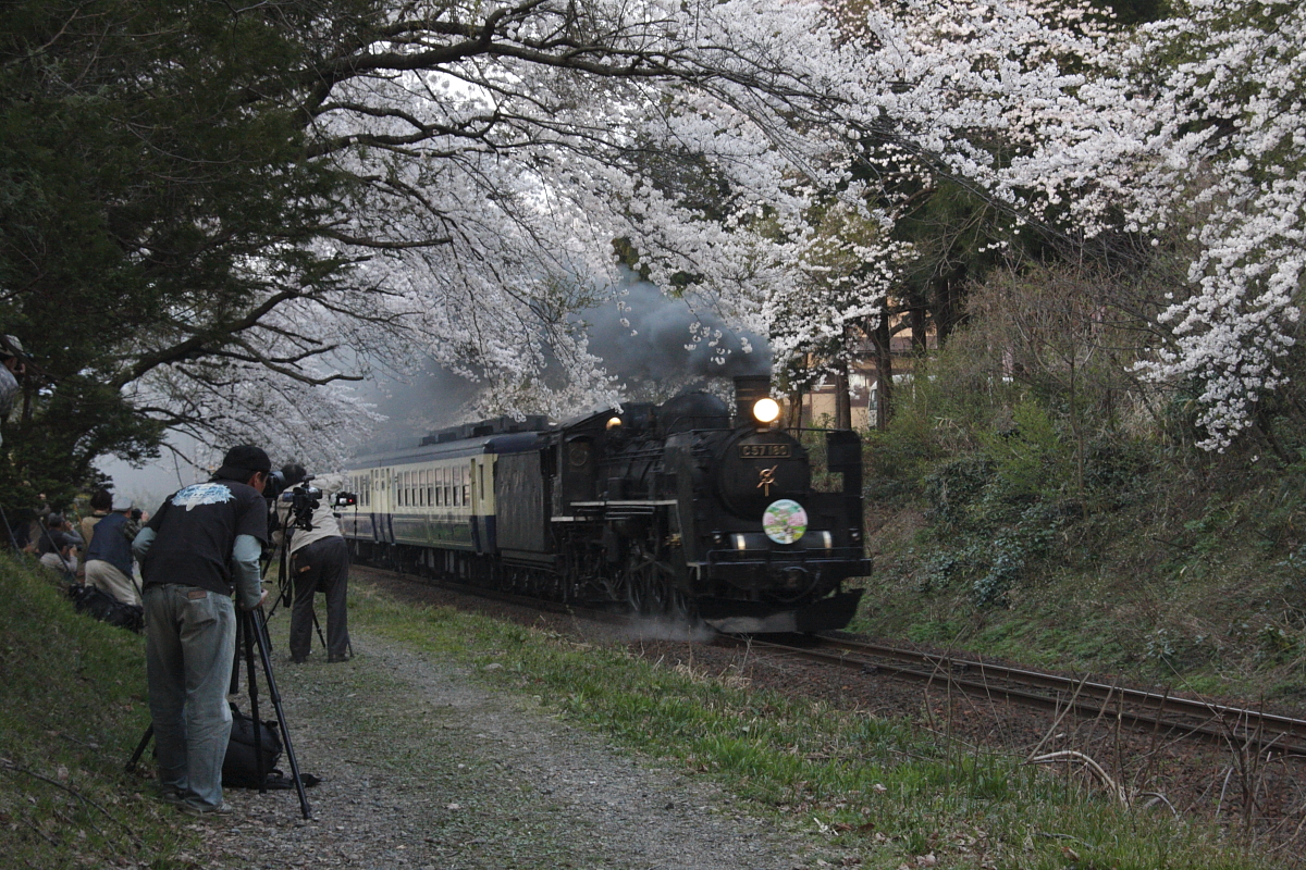
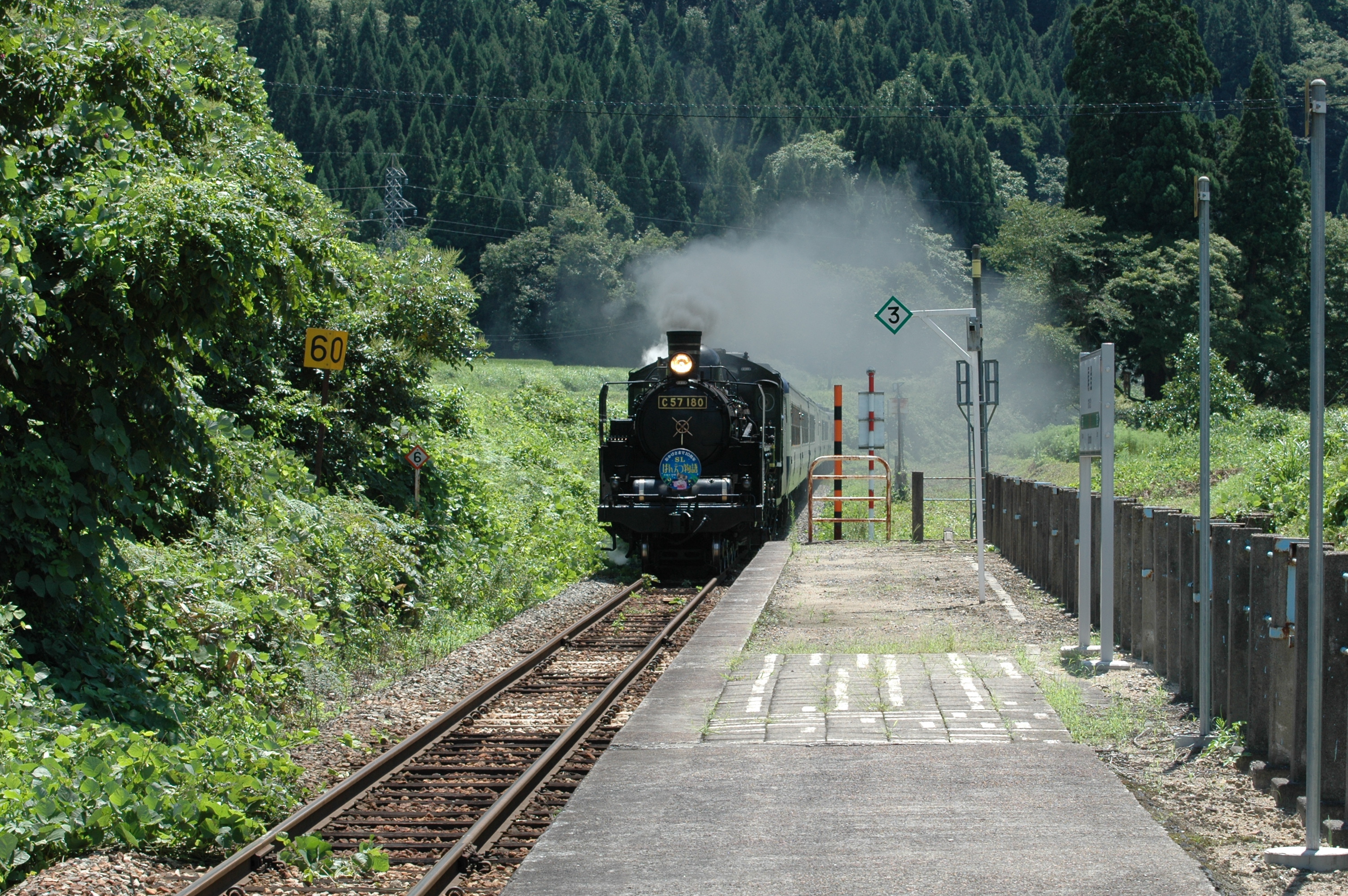
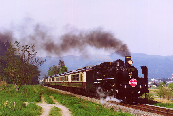
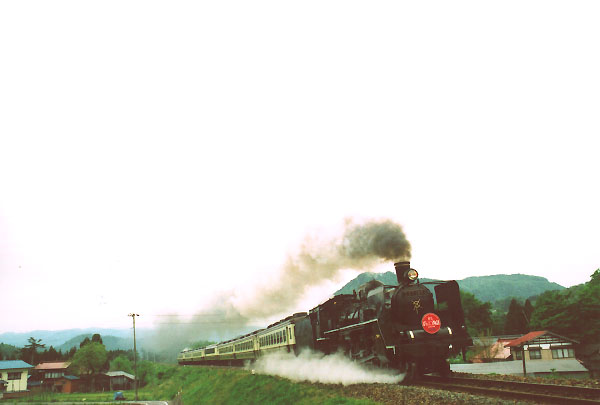
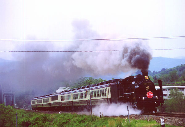
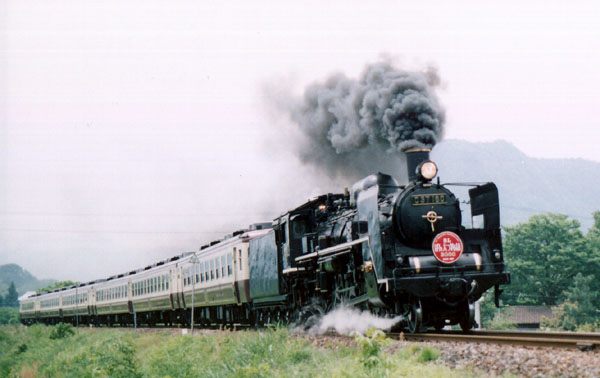
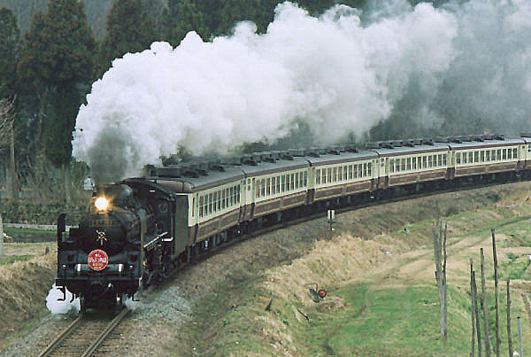
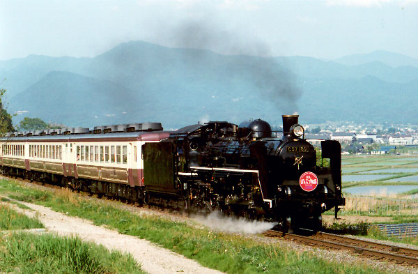
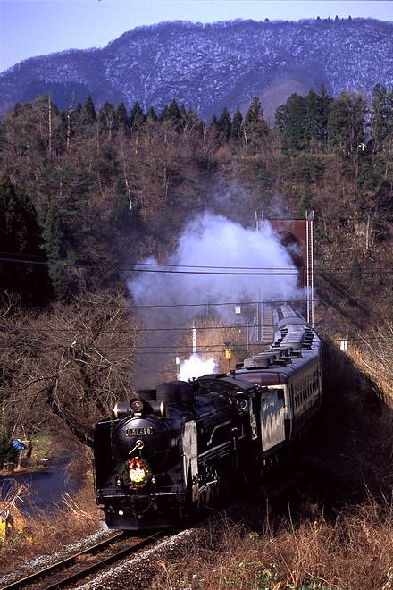
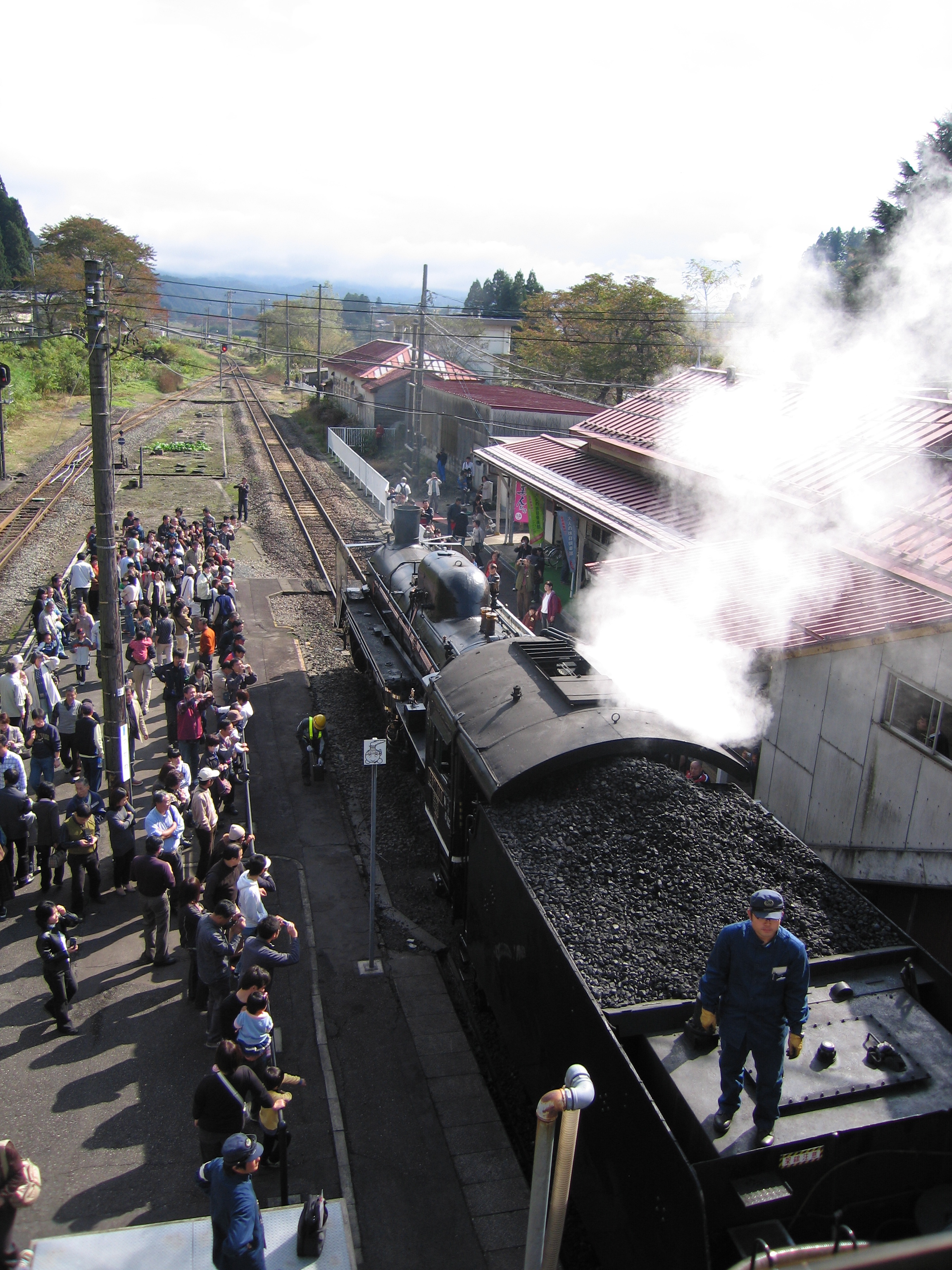
SL Banetsu Monogatari-go is a special express train that runs on a 126-kilometer track from Niigata to Aizuwakamatsu in Fukushima. On an approximately 3.5-hour ride, it stops at 10 stations on the way to Aizuwakamatsu and at nine stations on the way back. Passengers can enjoy a one-way trip to either destination or a round trip on weekends and holidays mainly from April to November. This steam locomotive is a C57-180 type train that was in service from 1946 to 1969. By restoring and repairing the train that had been stored at an elementary school in Niitsu City, its routine run on the Banetsu line began in April 1999. The interior of the train and the uniform of the crew are designed in a style unique to the Taisho era which is also the period when the Banetsu line was opened. The track located along the Agano River runs in a beautiful natural setting. The train stops for approximately 10 to 15 minutes between two of the stations, allowing passengers some time to take pictures. While fully enjoying seasonal scenery with features such as fresh green leaves and crimson foliage, you can experience a pleasant ride on an old-fashioned steam locomotive.
Photos
Timetable
Just for anyone wanting to catch this train, here are some pointers to grabbing tickets. The train runs usually twice each weekend, sometimes only in one direction, see the website and follow these notes:
- The current timetable is here
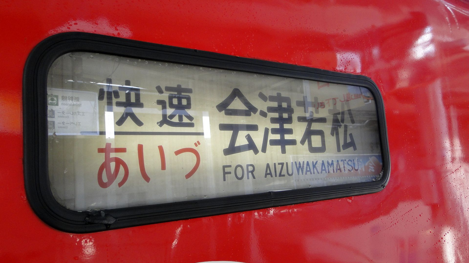
- [Green] 新潟~会津若松(往復運転)
Niigata to Aizuwakamatsu RETURN trip. - [Pink] 新潟→会津若松(片道運転)
Niigata to Aizuwakamatsu one-way ONLY trip. - [Yellow] 会津若松→新潟(片道運転)
Aizuwakamatsu to Niigata one-way ONLY trip.
- [Green] 新潟~会津若松(往復運転)
As for the 'busy' periods:
- Standard weekends are 'boring' for locals, so there's usually no direct hurry to get tickets.
- The XMAS Special is ridiculous and getting tickets is impossible.
My experiences with SL Banetsu
- Saturday 27th June 2009
- Had Japan-wide railpass, went to Tokyo Midori no Madoguchi office the day before and reserved my seat. (very easy with basic Japanese)
- Arrived at 9am to Niigata station and heard an announcement: People wanting to travel Aizuwakamatsu should use Platform 1 (SL is Platform 9 or so.)
- Asked station attendant, showed ticket, and he told me "today SL nai."... no reason was given.
- XMAS Special Saturday 19th December 2009
- Had Japanese friend in Australia call JR Tokyo office on 16th November 2009 to reserve tickets, no luck, they said you can do it online.
- Created account with her assistance on JR East ekinet: Could see SL Banetsu on other days but you can only book one month ahead.
- Came to 19th November 2009 and there was still no visibility of XMAS SL for 19th December 2009.
- Had friend call Japan again, they said it could not be booked online and over the phone bookings required a "view plaza" credit card.
- Requested another friend in Japan to get tickets in person at Tokyo station. He couldn't make it for a week and was to get them on the 28th of November.
- Australian friend called again on 26th November and ALL 3 XMAS special trains are fully booked.
My recommendations
- If you are going for a special service (there's a few in November and the XMAS specials in December) then go to Tokyo Midori no Madoguchi the morning of the day one month before the travel date. You can only book them one month before, and I'm not sure, but I'd wouldn't be surprised if there is a queue.
- Even if you have a ticket in hand, you should probably call Niigata station, or someone else in charge, to be certain that the SL is running on your day of travel.
My plan of attack now
- Saturday 19th December 2009
- Catch the Shinkansen to Koriyama and then the Banetsu line via Aizuwakamatsu to Shiokawa.
- Take a photo of that damn SL even if it kills me.
Bamboo SL Sound Generator
Early this month, I was in Sydney for a weekend and it co-incided with the AMRA Annual Model Railway Exhibition. I was disappointed to not see the usual Japanese Layout by a well known Australian modeller in the Japanese N Scale realm... but found enough goodies in the 2nd-hand junk boxes to satisfy my need for Japanese stock.
An EF81 (missing one panto and other bits) was still for sale from another seller for $80 and I passed on it again as, although I'm sure it'll run fantastically, I don't want to have to spend the extra money (and time search Poppondetta) for all the missing components.
And then... the find of the day... A, and I quote ”BB サウンドシステム SLドラフトN” or translated to: "BB Sound System SL Draft N". [Note: SL stands for Steam Locomotive in Japanese, they've coined the acronym.] When I saw it, I could only guess that it made SL sounds... and should be towed behind an SL. I asked the price, was told $10 and I didn't even ask if it worked, as I just wanted to get it and test it instantly.
On the train back to the city (2 hour ride) I read the instructions... hah... read them like a picture book! I could read the Katakana.. and that hinted something at a 'Power pack' and 'SCR timing pulse'. I thought I'd just bought a lemon that required some magic to get the chuffing happening... boy was I wrong!
If anyone wants to look at this image and give me a proper translation of it then go ahead... I'll post it here. Otherwise, when I get the time, I'll attempt to type it in to Google translator and see what it spits out. I really should've studied Kanji further after Uni ![]()
Inspecting the Kato WAMU freight car (damn heavy!) I saw that there was a reed switch and a magnet glued to the axle. Primitive technology from Japan... but considering the age of the paper the instructions are on, I'm guessing this whole thing is over 10 years old; but i'm yet to actually research it. Anyway, when rotating the axel you could hear the reed-switch clicking... meaning that it would be the 'pulse' required.
Opening it up, very gently, I found a reasonably dated PCB with quite large components.. but everything fitting nicely. There is a standard (what looked like a microphone) speaker mounted downwards and they've also added weights on the inside of the shell.
Finally, tonight, I put some voltage to the unit. I had to turn my Kato Powerpack up to notch '2' to get it hissing... and it sounds good!... I then pushed it along the tracks and the chuffing started... I realised that I could quickly get it to chuff way too fast and sound like a machine gun. After attaching my MicroAce steamer, I realised the main issue; the voltage required to start the sound was so high that the steamer was already flying. At this speed, although it sounded ok, it was still too fast to be enjoyed. When there was no loco on the tracks and the voltage was high, the sounds were great... you could even lock the reed switch open (at the sweet spot) and the chuff would continue forever... as in when an SL releases pressure at the end of a trip.
I then had a closer look at the circuit board to see if I could drop the required voltage to get the sound moving and something dawned on me... The sound worked in both directions... meaning that the circuitry had to work either way the DC voltage was supplied... this meant it had to have a bridge-rectifier in it already... DCC AC Voltage here I come!!!!
Of course, I ran out of time to test it on DCC and I also have no SLs DCC'd up. My MicroAce steamer seems to have a large enough tender... but I love that thing and don't want to hurt it. It also manages to suck power through it's driving wheels and so it'll be a task to convert it.
Videos!
This is the unit running on DCC. I don't have any steamers converted to DCC yet, so I put it in the middle of my 'Aizu Renewal' set. Apart from grotty wheels and tracks, the sound is great.
These videos haven't aged well!
Time is a figment of your imagination.
This is amazing, I was just looking at the main page of this site and realised it's nearly been a year since I've posted any real content!
I can't say I have any more content to post today either... I've been busy on weekends with life (moving state, etc..) and so I haven't had much of a chance to do any work on the models. I'm currently shifting to the state I bought the Shinkansen layout from... how ironic. The layout (due to taking up half of the parents garage) has now been all but deconstructed and boxed. I intend on turning it into a dog-bone, but an L-shape, with a single join. I have 4 weeks to do this, and since sleeping 40 metres from the layout, should see progress. The goal will be to then be able to store this layout on shelves in the garage and not consume too much space.
I've also been busy (call it an addiction) checking out Yass Junction.
Check my page out on the yellow links above... Yass is the closest 'Main South' station to Canberra and gets a lot of good traffic on a Saturday. I usually venture to get down there just before 0600 to see the grain trains, but it all depends on the weather.
Anyway... more news as I get to it.
Random Photos
Search
Tags
Links - Click for details
- Abandoned Rails (Japan)
- AIRLINE (Shinkansen Photography)
- Akihabara Station
- annexpressのブログ
- Australian Model Railway Magazine
- DCC普及協会ホームページ (Japanese DCC)
- Dead Section (Japanese Track Diagrams)
- Delicious Things (Japanese N Scale DCC)
- Densha Wotorou
- Digital Direct for Windows (DCC Server)
- Don's Dream World – AMAZING N Scale Japanese Layout
- Hatena::Diary
- Japanese N-Scale Modeling Forum
- JR Chiisai
- Kaz-T's blog レインボーライン (Rainbow Line)
- LED Resitance Calculator
- Masioka
- Poppondetta Blog
- RailFan Magazine, Japan
- Railmind
- Railway Travelers' Room
- Serenity Valley
- Shashinka Ichiban
- Shuzuku
- Sumida Crossing
- The next station is…
- Tomix N Gauge Track and Japanese N Gauge Trains
- TT Forums (Transport Tycoon Deluxe)
- 名鉄尾西線の貨物列車 (Nagoya: Meitetsu Freight)
- 日本型Nゲージ DCC改造例のご紹介 (Okiraku DCC)
- 泰 茅 轍 道 (Taichi Railway)
- 箱庭登山鉄道製作記 (Hakone-Tozan Layout Blog)
Archive
- July 2026
- May 2026
- April 2026
- March 2026
- February 2026
- January 2026
- November 2025
- October 2025
- September 2025
- August 2025
- July 2025
- June 2025
- February 2025
- January 2025
- November 2024
- September 2024
- August 2024
- July 2024
- June 2024
- May 2024
- April 2024
- March 2024
- February 2024
- December 2023
- October 2023
- September 2023
- August 2023
- July 2023
- June 2023
- May 2023
- April 2023
- March 2023
- December 2022
- November 2022
- October 2022
- April 2022
- March 2022
- February 2022
- January 2022
- December 2021
- November 2021
- September 2021
- August 2021
- July 2021
- May 2021
- March 2021
- February 2021
- January 2021
- October 2020
- September 2020
- August 2020
- July 2020
- June 2020
- May 2020
- April 2020
- March 2020
- January 2020
- December 2019
- November 2019
- October 2019
- September 2019
- August 2019
- July 2019
- June 2019
- April 2019
- March 2019
- February 2019
- January 2019
- December 2018
- November 2018
- October 2018
- September 2018
- August 2018
- July 2018
- June 2018
- May 2018
- April 2018
- March 2018
- January 2018
- December 2017
- November 2017
- October 2017
- September 2017
- August 2017
- July 2017
- June 2017
- May 2017
- March 2017
- February 2017
- January 2017
- December 2016
- November 2016
- October 2016
- September 2016
- August 2016
- July 2016
- June 2016
- May 2016
- February 2016
- November 2015
- October 2015
- September 2015
- August 2015
- July 2015
- June 2015
- May 2015
- April 2015
- March 2015
- February 2015
- January 2015
- December 2014
- November 2014
- August 2014
- July 2014
- May 2014
- April 2014
- March 2014
- December 2013
- November 2013
- October 2013
- June 2013
- August 2012
- April 2012
- March 2012
- February 2012
- November 2011
- October 2011
- September 2011
- July 2011
- June 2011
- May 2011
- April 2011
- March 2011
- February 2011
- January 2011
- December 2010
- November 2010
- October 2010
- September 2010
- August 2010
- June 2010
- May 2010
- April 2010
- March 2010
- February 2010
- January 2010
- December 2009
- November 2009
- October 2009
- August 2009
- January 2009
- December 2008
- November 2008
- October 2008
- September 2008
- July 2008