Picked this up recently and loved the design and specifications. It needed more RAM though, so I started unscrewing it to find the relevant slot. Turns out there's minimal effort needed... not even a screwdriver! Usually you get a panel underneath with a cute RAM icon, or somesuch, but there was no such thing on this unit.
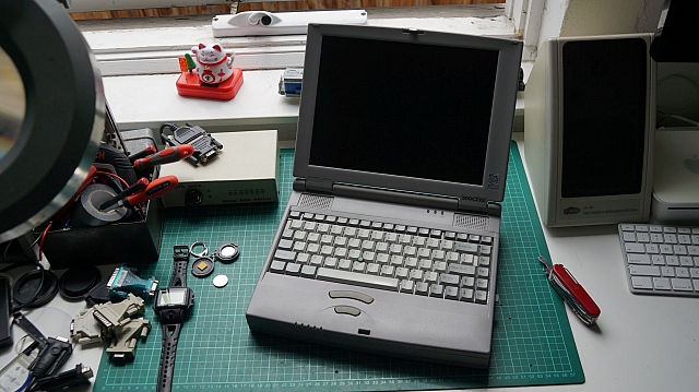
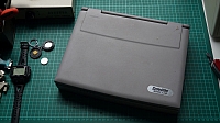
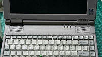

Instead... there's a lever-point on the right-hand-side of the unit, on the edge of the 'bevel' that runs along the top of the keyboard. Once popped out, the keyboard nicely lifts up and you have full access to the RAM slot.
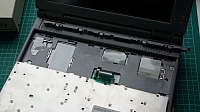
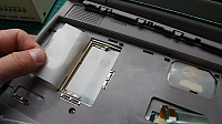
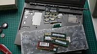
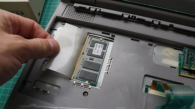
The trusty box-o-crap was emptied and all laptop RAM shown. 4 were a good fit, but all SDRAM. Unfortunately this unit only accepts EDO!
Saw this on eBay... no one else bid on it? Are you serious? It's one of the first smart watches! It was also one of the first to have its own software development kit.
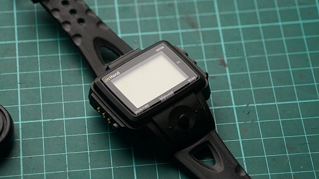
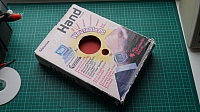
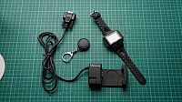

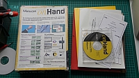
Totally reminiscent of a Casio, it's a chunk Matsucom OnHand PC which is actually the american clone of the Seiko Ruputer. In the package is a whole lot of documentation, software, the watch, a docking station and a cute little extra battery holder.
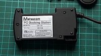
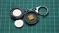
I expected CR2032 coin cell batteries, but it turns out it wanted CR2025s? I went off to find some...
Using it
I was immediately presented with "Fatal Error" after turning it on. The default action is to try and open "My Computer", so I assume that area of memory is crap.
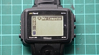
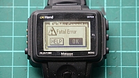
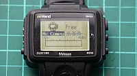
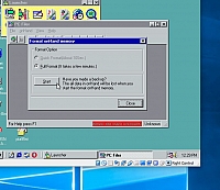
I booted my Windows 98se VM and plugged through the serial port. We were connected in no time and I was straight-away warned that the internal memory was rubbish. A quick format later and I had a connected watch!
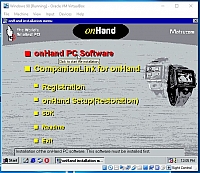
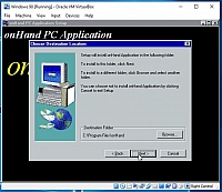
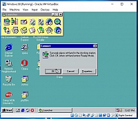
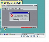

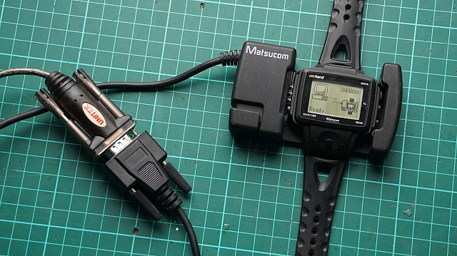
The file browser kept throwing an error that shortcut.ini was missing, so I created an empty file in the relevant directory, which successfully shut the error up. I wonder what software I can put on this thing?
The community still exists!
There's a whole raft of software at PC On Hand. This website actually has all the information you could ever want. If you're bored, it seems you can even convert movies into short animations to play on your watch.
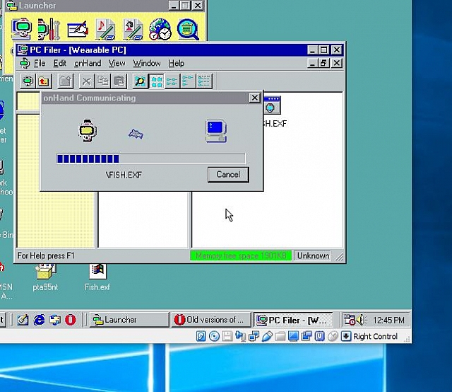
I quickly downloaded the fishtank and copied it to the watch with zero effort required.
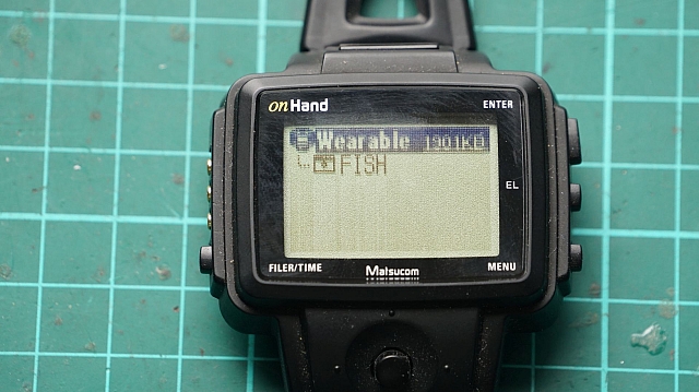
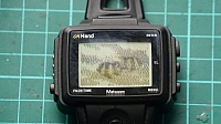
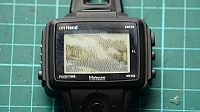

Yup... Fish. Worked nicely... EXF seems to be the compiled executable for the watch and it was seen as such in the file browser after copying. It's then a really quick navigation on the watch itself and, before you know it, you've got a mini aquarium on your wrist!
Software Development
PcOH-C For Windows is here, but they want you to register to download. I tried to do so, as I'm a legitimate human and was happy to see what random emails they wanted to send. Regardless, the signup process is dead... so the file is out of reach... or is it? I changed the URL from .asp to .zip and, you guessed it, the 1.6mb of glory downloaded. Here's a version just for keep-sake. The SDK is required, and that URL doesn't work either... so here's the entire product CD.
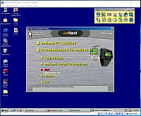
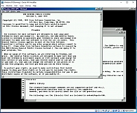
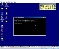
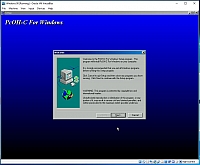
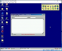
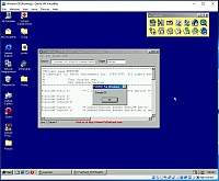
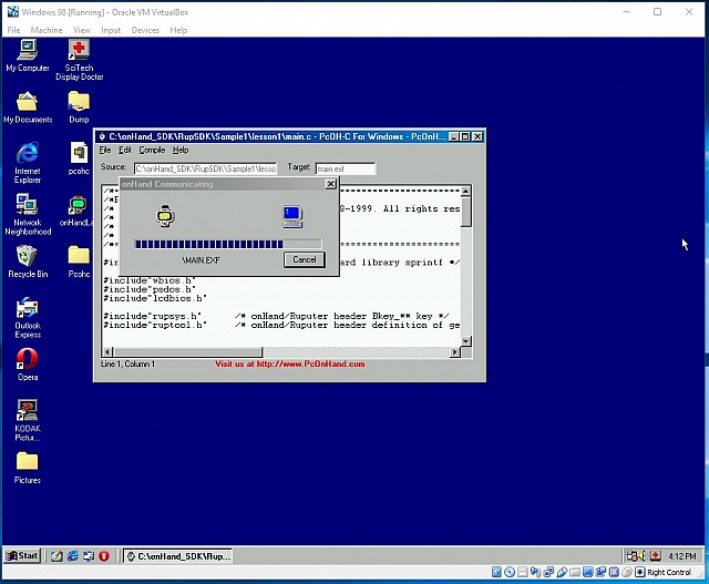
There's a few samples in PConH and I quickly compiled the first one. MAIN.EXF was created and I was able to upload it to the watch straight from the IDE. Before that though, the IDE has an emulator in it! You don't even need to deploy to your watch to test!
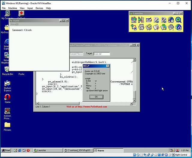
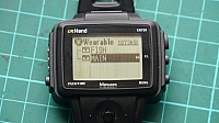
I copied it to the watch anyway...
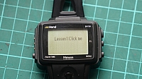
It also executed perfectly fine and, as expected, the relevant indicator popped up when pressing the joystick directions. The best part was that you can do diagonal actions as well... might come in very handy for a game!
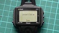
What's next? I think this watch deserves a mini-model-railway.
Have always had a soft-spot for this country. The climate and landscape is awesome, and so are the people and food. Let's also not forget about the IT/Electronics/Junk shopping! Oh yeah, they have railways too... of quite a few kinds! For accommodation, I highly recommend the Sekeping Resorts chain of locations. I don't know if they came before or after AirBnB, but it's the same idea. Someone has developed small neighbourhood properties into temporary accommodation. The first stop was Sekeping Tenggiri, right in the mix near Bangsar and it was fantastic!

Just bring mosquito repellant!
Bangsar
Just east of the main city is a vibrant suburb with a lot of ex-pats. There's great malls and great bars/clubs/restaurants... and also great accomodation. From the station you can also see just about all modes of transit! Bangsar Station has a great view of the airport line and the main rail line. There was a bit of trackwork being undertaken, so all trains had to come to a halt for single-line-working. No freight was seen, but works trains were around. There's also a few pedestrian overpasses down the line towards MidValley Mall which provide great views also.


Chinatown
Always a favourite, in any country. The flea markets are amazing at 7am in the morning. Supposedly Saturday morning is the best? Get there early (i.e. 6-7am) as it gets really hot really quickly and the sellers pack up quick. Expect crowds, junk and a sensory overload. Make sure your belongings are safe in secure bags and pockets! I found a few cool PCMCIA devices and a Sony Clie... for princely amounts of around AUD$2.00. And yeah, Maccas for breakfast.


There's also a cute little bi-directional monorail running through town. It actually starts right back at KL Sentral and takes you into the IT district.


Kuala Lumpur Station
This is a beautiful station, but also really a relic of what the railway used to be. With all the new above-ground modes of transport, this station doesn't see much use at all. It's also not overly-well connected to the rest of the network. KL Sentral, with it's mall and multi-mode connections, is the proper transit station. Regardless, this station is still beautiful and worth a visit! Unfortuantely, platforms 3 and 4 were closed for maintenance; fortunately, there was a railset train in operation!

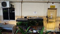


The express to Butterworth came and left as I was checking out the works train.


From the outside, you can actually get shots of the main station building through the cloudy windows... it's a bit of a shadow of its former self!


Across the road is the main KTMB office.


And then... the best part. You can walk the full length of the platform north and end up in Chinatown/Central Market. It was all very much under-construction, to the point where they had a second works train moving spoil around. And guess what? It was a freeeeeeekin DD51 from Japan! In perfectly AWFUL condition!


Serendah
After an amazing 3 days in the jungle at Sekeping Serendah, it was time to get back to the big smoke. This wasn't as easy as expected... getting a taxi from the resort was impossible and the owner's car was misfiring amazingly. I'm actually surprised we made it back and forth.

Anyway, it was down to Serendah Station where I, for some reason, expected a higher frequency of services.


One EMU bolted through, and then people starting appearing on the platform... hopefully a stopper would come through soon. Of course, before that, a light engine bolted through... was that a blue tiger!?!


And then a real freighter! Woo hooooo....

And that was that... an actual service stopped through and took us quickly to a transfer station as the main line into KL was under repair.
From the Rooftop of Alila Bangsar Hotel
This was a nice surprise... the final hotel in Malaysia and a perfect location! The view from the hotel rooms was fantastic. Southbound you get to see the monorail depot and airport trains.

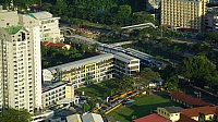


And then the roof! From the roof, you get to swim in the pool (or eat dinner) and watch the trains pass by the base of the building. I probably took waaaaaay too many photos.


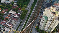


The sunset is fantastic... and there's, of course, other random things to look at...



Putrajaya and Cyberjaya
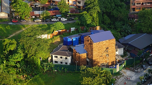
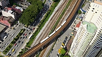
The main target was the Morrocan Mosque, but the take-away was being allowed into the derelict monorail station at the main train station! I'd seen the stubs of decrepit monorail track and had wondered how the german designers had manage to infiltrate Malaysia so well with their technology (it didn't survive in Sydney either.) Of course, this station had been shut down and truncated for quite a while and there was even a new over-ground rail system being extended down to the area.

So those two rails above are the truncated Monorail. Here's why... the LRT is on it's way to this location.


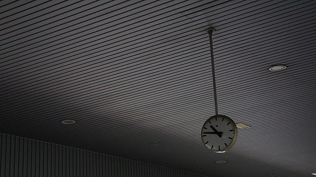
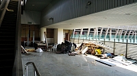
But then the juicy part... the actual monorail station upstairs...
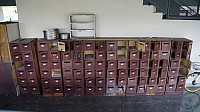
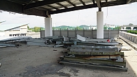
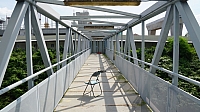


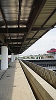

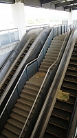

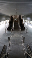
There was a cute little track machine down this end of town also.


It was then a quick trip on the EMU back to Bangsar and then a late evening flight back to Avalon. Skybus actually runs a pretty damn good service, connecting to the Air Asia X flights!
I'll be in Japan again shortly, so have been monitoring the Shin-Osaka Webcam to see if there aren't regular movements that aren't well-known or scheduled. There are slots in the timetable, that I've mentioned before, which are for ad-hoc movements. So sometimes you can guess the timing... but other times the movements are just random... like this one!

A DD51 towing a DE10. Nice.
I'd picked this Kodak DC50 camera up for a steal at a local flea market and had already had success taking photos to a PCMCIA storage card. I'd also already created a serial cable and had used Virtual Box to pull the internal images off. The whole method was a little clunky, so I decided to use kdcpi as a base to write a quick app in C# to get the data myself. I was pretty close ... but kept failing some CRC checks... so I decided to cheat and snoop in on the original conversation.
Virtual Box to Camera
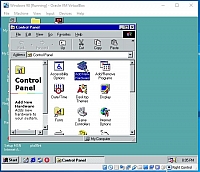
If you just want to use VirtualBox to talk to your camera, then go to the link above. There you'll find everything you need to know to get it set up. One point though, if you don't tell Windows 98 that you have a serial port when installing, then you'll need to fight through the Add New Hardware Wizard to get one installed. I had cheated and piped through a USB Serial port first, but then worked out that I needed to re-add the base serial port.
![2019-02-17 20 06 26-Windows 98 [Running] - Oracle VM VirtualBox](https://gallery3.otenko.com/rest/data/19281?size=thumb)
![2019-02-17 20 13 25-Windows 98 [Running] - Oracle VM VirtualBox](https://gallery3.otenko.com/rest/data/19286?size=thumb)
Once that was out of the way, I used the USB Serial to connect through to the camera and revived the software I built for debugging DOS Interlnk here to snoop on the data. To map the serial ports through, I used Eltima's Virtual Serial Port. It's actually awesome!
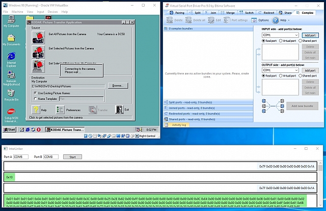
Yessss.... It worked perfectly. The conversation was captured and was already showing some hints as to why my initial C# code wasn't working.
Decoding Conversation
From here I could compare the real conversation to mine. Already I could see that I was putting the last byte of the previous 1024-byte block as the first in the next. No wonder checksums were failing! Anyway, here's the conversation from "Hello", to "What Images do you have for me?" and "Give me that image, there!".
0x7F 0x00 0x00 0x00 0x00 0x00 0x00 0x1A
0xD1 0x01 0x01 0x01 0x0A 0x01 0x00 0x01 0x00 0x02 0x00 0x3C 0x00 0x00 0x25 0x07 0x75 0x00 0xFF 0x00 0x00 0x00 0x00 0x00 0x00 0x00 0x00 0x0C 0xE4 0x00 0x00 0x00 0x00 0x00 0x00 0x00 0x0B 0x00 0x01 0x00 0x08 0x00 0x02 0x00 0x00 0x00 0x00 0x00 0x01 0x00 0x00 0x00 0x00 0x00 0x00 0x00 0x00 0x00 0x00 0x00 0x00 0x00 0x00 0x00 0x00 0x00 0x00 0x00 0x00 0x00 0x00 0x00 0x00 0x00 0x00 0x00 0x00 0x00 0x00 0x00 0x00 0x4B 0x6F 0x64 0x61 0x6B 0x20 0x44 0x69 0x67 0x69 0x74 0x61 0x6C 0x20 0x43 0x61 0x6D 0x65 0x72 0x61 0x20 0x35 0x30 0x20 0x20 0x20 0x20 0x20 0x20 0x20 0x20 0x00 0x00 0xFF 0xFF 0xFF 0xFF 0xFF 0xFF 0xFF 0xFF 0xFF 0xFF 0xFF 0xFF 0xFF 0xFF 0xFF 0xFF 0xFF 0xFF 0xFF 0xFF 0xFF 0xFF 0xFF 0xFF 0xFF 0xFF 0xFF 0xFF 0xFF 0xFF 0xFF 0xFF 0xFF 0xFF 0xFF 0xFF 0xFF 0xFF 0xFF 0xFF 0xFF 0xFF 0xFF 0xFF 0xFF 0xFF 0xFF 0xFF 0xFF 0xFF 0xFF 0xFF 0xFF 0xFF 0xFF 0xFF 0xFF 0xFF 0xFF 0xFF 0xFF 0xFF 0xFF 0xFF 0xFF 0xFF 0xFF 0xFF 0xFF 0xFF 0xFF 0xFF 0xFF 0xFF 0xFF 0xFF 0xFF 0xFF 0xFF 0xFF 0xFF 0xFF 0xFF 0xFF 0xFF 0xFF 0xFF 0xFF 0xFF 0xFF 0xFF 0xFF 0xFF 0xFF 0xFF 0xFF 0xFF 0xFF 0xFF 0xFF 0xFF 0xFF 0xFF 0xFF 0xFF 0xFF 0xFF 0xFF 0xFF 0xFF 0xFF 0xFF 0xFF 0xFF 0xFF 0xFF 0xFF 0xFF 0xFF 0xFF 0xFF 0xFF 0xFF 0xFF 0xFF 0xFF 0xFF 0xFF 0xFF 0xFF 0xFF 0xFF 0xFF 0xFF 0xFF 0xFF 0xFF 0xFF 0xFF 0xFF 0xFF 0xFF 0xFF 0x87
0x41 0x00 0x96 0x00 0x00 0x00 0x00 0x1A
0x55 0x00 0x00 0x01 0x00 0x00 0x00 0x1A
0xD1 0x01 0x01 0x00 0x01 0x00 0x00 0x00 0x00 0x00 0x01 0xF3 0x00 0x23 0x64 0xF4 0x0E 0x01 0x00 0x0D 0xAC 0x00 0x00 0x00 0x00 0x09 0x20 0x00 0x00 0x00 0x00 0x0C 0xDC 0x00 0x19 0x00 0x00 0x00 0x44 0x43 0x49 0x30 0x30 0x31 0x4C 0x00 0x00 0x00 0x00 0x00 0x00 0x00 0x00 0x00 0x00 0x00 0x00 0x00 0x00 0x00 0x00 0x00 0x00 0x00 0x00 0x00 0x00 0x00 0x00 0x00 0x00 0x00 0x00 0x00 0x00 0x00 0x00 0x00 0x00 0x00 0x00 0x00 0x00 0x00 0x00 0x00 0x00 0x00 0x00 0x00 0x00 0x00 0x00 0x00 0x00 0x00 0x00 0x00 0x00 0x00 0x00 0x00 0x00 0x00 0x00 0x00 0x00 0x00 0x00 0x00 0x00 0x00 0x00 0x00 0x00 0x00 0x00 0x00 0x00 0x00 0x00 0x00 0x00 0x00 0x00 0x00 0x00 0x00 0x00 0x00 0x00 0x00 0x00 0x00 0x00 0x00 0x00 0x00 0x00 0x00 0x00 0x00 0x00 0x00 0x00 0x00 0x00 0x00 0x00 0x00 0x00 0x00 0x00 0x00 0x00 0x00 0x00 0x00 0x00 0x00 0x00 0x00 0x00 0x00 0x00 0x00 0x00 0x00 0x00 0x00 0x00 0x00 0x00 0x00 0x00 0x00 0x00 0x00 0x00 0x00 0x00 0x00 0x00 0x00 0x00 0x00 0x00 0x00 0x00 0x00 0x00 0x00 0x00 0x00 0x00 0x00 0x00 0x00 0x00 0x00 0x00 0x00 0x00 0x00 0x00 0x00 0x00 0x00 0x00 0x00 0x00 0x00 0x00 0x00 0x00 0x00 0x00 0x00 0x00 0x00 0x00 0x00 0x00 0x00 0x00 0x00 0x00 0x00 0x00 0x00 0x00 0x00 0x00 0x00 0x00 0x00 0x00 0x00 0x00 0x00 0x00 0x00 0x00 0x00 0x00 0x00 0x00 0x00 0x00 0x00 0x00 0x00 0x00 0x00 0x00 0x00 0x00 0x3D
0x56 0x00 0x00 0x02 0x00 0x00 0x00 0x1A
0xD1 0x21 0x11 0x12 0x21 0x22 0x12 0x22 0x31 0x01 0x21 0x22 0x12 0x31 0x32 0x12 0x22 0x22 0x12 0x22 0x22 0x12 0x21 0x22 0x11 0x22 0x12 0x11 0x21 0x22 0x11 0x21 0x22 0x02 0x21 0x22 0x12 0x31 0x22 0x11 0x21 0x22 0x11 0x21 0x22 0x01 0x21 0x22 0x01 0x21 0x22 0x01 0x21 0x22 0x01 0x21 0x21 0x01 0x21 0x22 0x01 0x21 0x21 0x01 0x21 0x21 0x01 0x21 0x21 0x01 0x21 0x21 0x01 0x11 0x21 0x21 0x21 0x21 0x21 0x21 0x21 0x21 0x21 0x11 0x21 0x21 0x21 0x21 0x21 0x21 0x21 0x21 0x21 0x21 0x11 0x21 0x10 0x11 0x02 0x22 0x21 0x22 0x22 0x21 0x22 0x22 0x22 0x22 0x22 0x21 0x23 0x22 0x21 0x12 0x22 0x11 0x12 0x22 0x21 0x22 0x22 0x21 0x22 0x23 0x21 0x12 0x22 0x11 0x12 0x22 0x21 0x22 0x22 0x11 0x22 0x22 0x21 0x22 0x22 0x11 0x12 0x22 0x21 0x12 0x22 0x11 0x12 0x22 0x11 0x12 0x22 0x21 0x12 0x22 0x11 0x22 0x22 0x11 0x11 0x12 0x11 0x11 0x11 0x11 0x11 0x12 0x11 0x11 0x11 0x12 0x22 0x12 0x22 0x12 0x22 0x22 0x12 0x12 0x12 0x12 0x12 0x12 0x12 0x12 0x12 0x12 0x12 0x12 0x12 0x12 0x11 0x12 0x11 0x22 0x12 0x12 0x22 0x21 0x12 0x23 0x22 0x12 0x22 0x21 0x12 0x22 0x22 0x12 0x23 0x22 0x12 0x22 0x22 0x22 0x22 0x22 0x12 0x22 0x22 0x22 0x22 0x22 0x11 0x21 0x22 0x11 0x22 0x22 0x11 0x22 0x22 0x12 0x22 0x21 0x12 0x22 0x21 0x11 0x22 0x21 0x11 0x22 0x21 0x11 0x22 0x21 0x11 0x22 0x22 0x11 0x22 0x21 0x11 0x22 0x21 0x11 0x12 0x21 0x11 0x11 0x21 0x11 0x11 0x21 0x01 0x11 0x21 0x21 0x22 0x22 0x22 0x21 0x22 0x21 0x21 0x21 0x21 0x21 0x21 0x21 0x21 0x21 0x21 0x21 0x21 0x21 0x21 0x11 0x11 0x21 0x02 0x22 0x21 0x22 0x22 0x21 0x22 0x22 0x22 0x12 0x33 0x21 0x22 0x22 0x22 0x23 0x22 0x22 0x12 0x22 0x22 0x22 0x21 0x21 0x22 0x22 0x11 0x22 0x22 0x21 0x22 0x22 0x21 0x22 0x22 0x21 0x12 0x22 0x21 0x22 0x22 0x21 0x22 0x22 0x21 0x12 0x22 0x11 0x22 0x22 0x11 0x12 0x22 0x11 0x12 0x22 0x11 0x12 0x21 0x11 0x12 0x22 0x11 0x11 0x12 0x11 0x11 0x22 0x11 0x11 0x12 0x12 0x12 0x12 0x22 0x12 0x23 0x22 0x12 0x12 0x12 0x12 0x12 0x12 0x12 0x22 0x12 0x12 0x12 0x12 0x12 0x12 0x12 0x12 0x11 0x22 0x12 0x12 0x22 0x22 0x12 0x22 0x22 0x11 0x22 0x22 0x22 0x32 0x22 0x11 0x33 0x22 0x22 0x23 0x22 0x12 0x32 0x22 0x22 0x22 0x22 0x12 0x22 0x21 0x12 0x22 0x22 0x12 0x22 0x22 0x12 0x22 0x22 0x12 0x22 0x22 0x11 0x22 0x22 0x12 0x22 0x22 0x11 0x22 0x11 0x12 0x22 0x21 0x11 0x22 0x21 0x11 0x22 0x21 0x12 0x22 0x21 0x11 0x22 0x21 0x11 0x12 0x21 0x11 0x11 0x21 0x11 0x21 0x22 0x21 0x22 0x21 0x22 0x22 0x22 0x21 0x21 0x21 0x22 0x21 0x21 0x21 0x21 0x21 0x21 0x21 0x21 0x21 0x21 0x11 0x11 0x21 0x02 0x22 0x21 0x22 0x22 0x21 0x23 0x22 0x22 0x12 0x22 0x22 0x22 0x22 0x21 0x22 0x22 0x22 0x22 0x33 0x21 0x23 0x32 0x22 0x22 0x33 0x22 0x22 0x32 0x21 0x23 0x22 0x21 0x23 0x22 0x22 0x23 0x22 0x21 0x12 0x22 0x21 0x12 0x22 0x21 0x12 0x22 0x11 0x22 0x22 0x11 0x22 0x22 0x21 0x12 0x22 0x11 0x22 0x22 0x11 0x12 0x22 0x11 0x12 0x22 0x11 0x11 0x12 0x10 0x12 0x21 0x12 0x12 0x12 0x12 0x12 0x23 0x13 0x23 0x22 0x23 0x22 0x22 0x22 0x22 0x12 0x12 0x12 0x12 0x12 0x12 0x12 0x12 0x11 0x11 0x22 0x12 0x22 0x33 0x22 0x12 0x22 0x32 0x22 0x22 0x22 0x22 0x33 0x22 0x22 0x65 0x36 0x6A 0x73 0xC6 0x68 0x63 0xA5 0x58 0x53 0x94 0x47 0x53 0x83 0x36 0x33 0x62 0x24 0x32 0x43 0x22 0x32 0x22 0x22 0x32 0x22 0x12 0x33 0x22 0x11 0x22 0x22 0x12 0x22 0x22 0x12 0x22 0x21 0x11 0x22 0x21 0x11 0x22 0x21 0x12 0x22 0x31 0x11 0x22 0x21 0x11 0x21 0x21 0x11 0x11 0x21 0x11 0x22 0x22 0x21 0x21 0x31 0x6B 0xCB 0xC7 0x9B 0xCB 0xBA 0xBA 0x98 0x86 0x65 0x54 0x42 0x21 0x21 0x21 0x21 0x21 0x21 0x11 0x22 0x13 0x22 0x12 0x12 0x22 0x21 0x22 0x22 0x22 0x13 0x22 0x21 0x13 0x22 0x78 0x1C 0xCC 0xCB 0xCC 0xCC 0xCB 0xBC 0xCC 0xA8 0xCB 0xA8 0xBB 0xBC 0xCC 0xBB 0xBC 0xBB 0xBB 0xBC 0xBB 0xBA 0xBB 0xBB 0xBA 0xAB 0xBB 0xAA 0xAB 0xBB 0xAA 0xAB 0xBB 0xAA 0xAB 0xBB 0x42 0x82 0x22 0x21 0x12 0x22 0x21 0x12 0x22 0x11 0x12 0x22 0x11 0x12 0x22 0x11 0x12 0x12 0x11 0x11 0x12 0x13 0x12 0x22 0x22 0x22 0x5C 0xCC 0xBC 0xBB 0xBC 0xBB 0xBB 0xAB 0xAB 0xAB 0xAB 0xAB 0x42 0x12 0x12 0x12 0x12 0x12 0x11 0x32 0x12 0x12 0x32 0x22 0x22 0x22 0x22 0x12 0x22 0x22 0x22 0x33 0x22 0x22 0x88 0x1C 0xBB 0xCC 0x8B 0xA8 0xBD 0x7C 0xA9 0xCC 0xCC 0xBB 0xCC 0xAB 0xBB 0xCC 0xBB 0xBB 0xCB 0xBB 0xBB 0xBB 0xBB 0xAB 0xBB 0xBB 0xAA 0xBB 0xBA 0xAA 0xBB 0xBA 0xAA 0xBB 0xBA 0xAA 0x43 0x82 0x12 0x22 0x21 0x11 0x22 0x21 0x12 0x22 0x21 0x11 0x22 0x21 0x11 0x12 0x21 0x11 0x22 0x11 0x11 0x21 0x22 0x22 0x22 0x32 0x58 0xAA 0xA8 0xCB 0xAB 0xCB 0xBB 0xBA 0xBA 0xBA 0xB9 0xAA 0x51 0x21 0x21 0x21 0x11 0x21 0x21 0x21 0x02 0x22 0x21 0x22 0x22 0x22 0x13 0x22 0x21 0x22 0x22 0x22 0x23 0x23 0x76 0x19 0x9A 0xCB 0xAC 0xBB 0xBB 0xBA 0x98 0xCC 0xCC 0xCC 0x9A 0xAC 0xCC 0xBB 0xBC 0xCC 0xBB 0xBC 0xCB 0xBB 0xBB 0xBB 0xBA 0xAB 0xBB 0xAA 0xBB 0xBB 0xAA 0xA8 0x8A 0x86 0xC7 0x7A 0x41 0x82 0x22 0x21 0x12 0x22 0x11 0x22 0x21 0x12 0x12 0x22 0x11 0x11 0x22 0x11 0x22 0x22 0x11 0x11 0x22 0x12 0x22 0x22 0x12 0x22 0x4B 0x99 0xB7 0xCB 0x8C 0xBC 0xBC 0x98 0x5B 0xAB 0xAA 0x8A 0x52 0x12 0x12 0x12 0x12 0x12 0x12 0x42 0x03 0x22 0x32 0x22 0x22 0x23 0x12 0x22 0x22 0x32 0x22 0x33 0x22 0x22 0x76 0x2C 0xCC 0xDD 0xDB 0xCC 0xCC 0xB8 0x89 0x9C 0x9B 0xAB 0xCC 0xCB 0x98 0xCB 0xA9 0x87 0x99 0x98 0x78 0x8A 0x67 0x66 0xBB 0x79 0x9A 0xBB 0xBB 0xAB 0xBB 0xB9 0xA9 0x9B 0x69 0x99 0x53 0xA2 0x11 0x22 0x21 0x11 0x22 0x21 0x11 0x22 0x21 0x11 0x22 0x74
0x21 0x12 0x22 0x21 0x11 0x22 0x21 0x11 0x22 0x32 0x21 0x32 0x22 0x5C 0xD8 0x8C 0x8B 0x87 0x5A 0xC9 0x9A 0x64 0x7A 0xB6 0x87 0x61 0x21 0x21 0x21 0x21 0x11 0x21 0x42 0x03 0x32 0x64 0x24 0x44 0x21 0x23 0x32 0x22 0x23 0x33 0x21 0x23 0x32 0x65 0x1A 0xBC 0xA7 0x9A 0x9B 0xA8 0xDC 0xCB 0xBB 0x96 0x98 0xA7 0xCB 0xBB 0xBA 0xBC 0xCC 0xBA 0xBB 0xCC 0xAC 0x9A 0x99 0xAA 0xA4 0x35 0x32 0x24 0x32 0xAB 0x78 0x88 0x84 0xA8 0x89 0x63 0xA2 0x22 0x22 0x12 0x22 0x11 0x12 0x22 0x11 0x12 0x22 0x11 0x22 0x22 0x11 0x12 0x22 0x11 0x12 0x22 0x34 0x43 0x22 0x22 0x23 0x3B 0xCC 0xCB 0xA9 0xC7 0xBC 0xAC 0x8B 0x8A 0x22 0x58 0xA7 0x62 0x12 0x12 0x12 0x12 0x12 0x11 0x65 0x05 0x44 0x65 0x44 0x33 0x22 0x22 0x11 0x33 0x22 0x22 0x32 0x23 0x22 0x65 0x1A 0xBC 0x76 0x6C 0xCB 0xAC 0x9C 0xCC 0xDD 0xCC 0xBA 0xCC 0xCC 0xBB 0xCC 0xCC 0xBB 0xAA 0xAB 0xAA 0xCC 0xCB 0xBB 0x9A 0xAB 0xA8 0x64 0xD3 0x48 0x43 0x18 0x76 0xAA 0x97 0x77 0x76 0xB2 0x11 0x22 0x22 0x12 0x22 0x22 0x11 0x22 0x21 0x11 0x22 0x11 0x12 0x22 0x21 0x11 0x21 0x21 0x11 0x35 0x53 0x22 0x32 0x32 0x4C 0xCB 0xBC 0xDC 0x77 0xC8 0x8B 0xCA 0xA4 0xB2 0x29 0x89 0x81 0x21 0x21 0x21 0x21 0x21 0x21 0x32 0x05 0x43 0x32 0x14 0x31 0x22 0x22 0x23 0x22 0x22 0x23 0x22 0x23 0x22 0x63 0x1C 0xDD 0xA6 0xA9 0xA9 0x75 0x6D 0xDC 0xCC 0xCC 0xBC 0x85 0x98 0x9B 0xCB 0xAB 0xBB 0xBA 0xBC 0xCC 0xBB 0xB9 0xAC 0xAA 0xA6 0x44 0xBA 0xA3 0x32 0x21 0x26 0x77 0x58 0x66 0x58 0x76 0xB2 0x22 0x21 0x12 0x22 0x21 0x22 0x22 0x11 0x12 0x22 0x11 0x22 0x22 0x11 0x12 0x22 0x11 0x12 0x22 0x04 0x12 0x22 0x23 0x22 0x2D 0x8B 0xCD 0xB9 0xCC 0xB8 0xAC 0xBA 0xA6 0xB2 0x2A 0x9B 0x82 0x12 0x12 0x12 0x12 0x12 0x12 0x11 0x01 0x11 0x32 0x22 0x11 0x23 0x22 0x22 0x22 0x22 0x22 0x33 0x22 0x22 0x64 0x2C 0xCC 0xCD 0xDC 0xA8 0xA5 0x8D 0xB9 0xAA 0xCA 0x9A 0xDD 0xCC 0xCC 0xCC 0xB8 0xAC 0xCB 0xCB 0xBA 0xBA 0xBA 0x99 0xBB 0xCA 0xA6 0xBB 0xB3 0x23 0x32 0x2B 0xAA 0x99 0xC7 0x87 0x89 0x92 0x12 0x22 0x22 0x11 0x22 0x21 0x11 0x22 0x21 0x11 0x22 0x22 0x11 0x22 0x21 0x11 0x22 0x21 0x12 0x01 0x21 0x32 0x32 0x32 0x3C 0xD7 0x9A 0xA9 0xDC 0xCB 0xBB 0xCA 0x93 0xB6 0x3A 0x89 0x91 0x21 0x21 0x21 0x21 0x21 0x21 0x00 0x02 0x21 0x22 0x23 0x33 0x22 0x23 0x33 0x22 0x33 0x22 0x22 0x23 0x32 0x42 0x1D 0xDD 0x65 0x67 0x8B 0x8A 0x8C 0xCB 0xAB 0x7B 0xBC 0xCC 0xCD 0xCC 0xCC 0xBB 0xBC 0xCB 0xBC 0xCB 0xCB 0xBB 0xCC 0x99 0xB6 0x7A 0xBA 0xA7 0x9B 0x32 0x17 0x69 0x7A 0x78 0x75 0x8A 0x92 0x22 0x21 0x22 0x22 0x12 0x12 0x22 0x12 0x12 0x22 0x11 0x12 0x22 0x11 0x22 0x22 0x11 0x12 0x22 0x01 0x23 0x23 0x23 0x22 0x2D 0xCD 0xCC 0xCC 0xBC 0xCB 0xBC 0xBC 0xB6 0x53 0x39 0x79 0x92 0x12 0x12 0x12 0x12 0x12 0x12 0x00 0x01 0x00 0x23 0x22 0x22 0x22 0x32 0x21 0x23 0x22 0x21 0x23 0x32 0x22 0x43 0x3C 0xCC 0x77 0x49 0x79 0x9C 0x5B 0xAB 0xBB 0xDC 0xCC 0xA9 0xBC 0xCC 0xCC 0xCA 0xBB 0xCC 0xCB 0xA8 0xCC 0xCB 0xAA 0xCB 0xC7 0x67 0x43 0x74 0x47 0xBB 0xB9 0x88 0xBB 0xB6 0x55 0xAB 0x72 0x22 0x22 0x11 0x11 0x22 0x22 0x11 0x22 0x21 0x11 0x22 0x21 0x11 0x22 0x21 0x11 0x22 0x21 0x12 0x00 0x22 0x32 0x32 0x22 0x3C 0x77 0xA8 0xDB 0x9C 0xCB 0xA7 0xCA 0x98 0xCB 0xB6 0x8A 0x91 0x21 0x21 0x21 0x21 0x21 0x21 0x00 0x01 0x11 0x21 0x23 0x33 0x22 0x23 0x32 0x22 0x23 0x32 0x22 0x23 0x33 0x32 0x2D 0xDD 0xBB 0xDD 0xDC 0xCC 0x9B 0xA8 0xCC 0xCA 0xBC 0xCC 0x8D 0xCC 0xCB 0xCB 0xCC 0xBB 0xBA 0xCD 0xCB 0xB8 0xA7 0xB9 0xBC 0xBB 0xBB 0xBB 0xCB 0xBB 0xB8 0x79 0xAA 0xB5 0x56 0x8B 0x83 0x32 0x21 0x12 0x22 0x21 0x12 0x22 0x11 0x12 0x22 0x11 0x22 0x22 0x11 0x12 0x22 0x11 0x12 0x22 0x01 0x22 0x23 0x23 0x23 0x2D 0x77 0x69 0xCD 0xAD 0xC9 0xBC 0xAB 0xAC 0xBB 0xA7 0x9B 0x82 0x12 0x12 0x12 0x22 0x12 0x11 0x10 0x00 0x00 0x33 0x22 0x22 0x32 0x23 0x21 0x33 0x32 0x21 0x32 0x32 0x22 0x33 0x3D 0xCC 0xAA 0x9C 0xCD 0xDD 0xD9 0x98 0xDD 0xDC 0xCC 0xBB 0xDC 0xCB 0xCC 0xCA 0x76 0xDC 0xBB 0xA9 0xB8 0xCB 0xBB 0xCC 0xCB 0xBB 0xCC 0xCB 0xAA 0xBC 0x99 0x9A 0x87 0x87 0x65 0xAA 0x72 0x12 0x22 0x22 0x11 0x22 0x21 0x12 0x22 0x21 0x11 0x22 0x21 0x11 0x12 0x21 0x12 0x22 0x21 0x11 0x00 0x21 0x21 0x32 0x32 0x3C 0x88 0x85 0xDB 0xC6 0x7B 0x99 0xCB 0xCB 0xBA 0x97 0x99 0x82 0x21 0x21 0x21 0x21 0x21 0x21 0x00 0x00 0x01 0x21 0x23 0x22 0x22 0x23 0x22 0x21 0x22 0x22 0x32 0x23 0x23 0x32 0x2D 0xDD 0x96 0x9A 0xAC 0xBA 0xD9 0xAC 0xCB 0xAB 0xBC 0xCB 0xBA 0xAC 0xCC 0xCC 0xCC 0xCC 0xBC 0xCC 0xCB 0xBC 0xCC 0xBB 0xBC 0xCC 0xBB 0xBB 0xBB 0x98 0x89 0x88 0x55 0x78 0x87 0x88 0x83 0x22 0x21 0x22 0x22 0x11 0x12 0x22 0x11 0x12 0x22 0x21 0x22 0x22 0x11 0x22 0x22 0x11 0x11 0x22 0x00 0x13 0x23 0x23 0x23 0x2D 0xBA 0xAB 0x9D 0xCC 0xAC 0xBC 0xBC 0xBC 0xBB 0x98 0x78 0x82 0x12 0x12 0x12 0x12 0x12 0x12 0x00 0x00 0x00 0x22 0x12 0x22 0x32 0x22 0x22 0x32 0x22 0x22 0x33 0x22 0x22 0x33 0x2C 0xCC 0xCD 0x79 0x99 0x88 0x97 0x88 0xDD 0xDC 0xCC 0xDD 0xCA 0xBB 0x87 0xAC 0xCC 0xCC 0xCC 0xBC 0xCC 0xCC 0xBB 0xCC 0xCB 0xBB 0xBB 0xBA 0xAA 0xA9 0xB8 0x77 0xBB 0xB8 0x64 0x89 0x52 0x22 0x22 0x21 0x12 0x22 0x21 0x11 0x22 0x22 0x11 0x22 0x21 0x12 0x22 0x21 0x12 0x12 0x21 0x11 0x00 0x22 0x22 0x32 0x22 0x3C 0x76 0xA9 0xDC 0xD9 0xBC 0xCB 0xCB 0xCB 0xCA 0xAA 0x98 0xA1 0x21 0x21 0x21 0x21 0x21 0x21 0x00 0x00 0x01 0x11 0x03 0x22 0x22 0x23 0x33 0x32 0x23 0x23 0x22 0x23 0x33 0x33 0x2D 0xDD 0x77 0xAC 0xCD 0xCC 0xCC 0xBA 0xCC 0xAD 0xDC 0xCC 0xCB 0xBB 0xB8 0xAC 0x08
0xCC 0xCC 0xBC 0xCC 0xBB 0xBC 0xCC 0xBB 0xBC 0xCC 0xBB 0xBA 0xAA 0x9A 0xAB 0xBB 0xBA 0xAB 0xBB 0xAA 0xA2 0x22 0x11 0x22 0x22 0x12 0x12 0x22 0x21 0x22 0x22 0x11 0x12 0x22 0x11 0x12 0x22 0x11 0x12 0x22 0x00 0x02 0x23 0x23 0x23 0x2D 0x77 0xBA 0x59 0x8C 0xBC 0xCC 0xBC 0xBC 0xBB 0xBB 0xAB 0xA2 0x12 0x12 0x12 0x12 0x12 0x11 0x00 0x00 0x00 0x11 0x02 0x11 0x23 0x22 0x21 0x23 0x32 0x22 0x32 0x22 0x22 0x33 0x2C 0xCC 0x99 0x9B 0xA9 0x79 0x98 0xA7 0xCC 0xD9 0x9C 0xCC 0xCC 0xCC 0xCC 0xCC 0xBB 0xCC 0xCC 0xBC 0xCC 0xCB 0xBB 0xCC 0xCB 0xBB 0xBC 0xBB 0xBB 0xBB 0xBB 0xBB 0xBB 0xBA 0xAA 0xBB 0xB2 0x12 0x22 0x21 0x12 0x22 0x22 0x11 0x22 0x21 0x11 0x22 0x21 0x11 0x22 0x21 0x11 0x11 0x21 0x11 0x00 0x11 0x22 0x22 0x32 0x3C 0x97 0xAC 0xDC 0xDC 0xCB 0xCB 0xCB 0xCB 0xCB 0xBB 0xBA 0xB1 0x21 0x21 0x21 0x21 0x21 0x21 0x11 0x01 0x01 0x00 0x03 0x22 0x22 0x12 0x32 0x22 0x23 0x32 0x22 0x23 0x33 0x32 0x2D 0xDD 0xCC 0xC9 0x68 0x85 0xAD 0xDC 0xCC 0xCD 0xDC 0xCC 0xCC 0xCC 0xCC 0xBC 0xCC 0xCC 0xBC 0xCC 0xBB 0xBC 0xCC 0xBB 0xBB 0xCB 0xBB 0xBB 0xBB 0xBA 0x8B 0xA7 0x9A 0x59 0x74 0x69 0x12 0x22 0x11 0x22 0x22 0x21 0x12 0x22 0x11 0x12 0x22 0x11 0x22 0x22 0x11 0x12 0x22 0x11 0x21 0x22 0x00 0x02 0x12 0x23 0x23 0x2D 0xC9 0x9D 0xCD 0xCC 0xBC 0xBB 0xA9 0x77 0x54 0x22 0x22 0x22 0x12 0x12 0x12 0x12 0x11 0x11 0x21 0x01 0x11 0x21 0x04 0x22 0x42 0x23 0x22 0x43 0x22 0x22 0x22 0x12 0x22 0x33 0x3C 0xCC 0xDD 0xDC 0xCC 0xDC 0xBC 0xB8 0xBC 0x6A 0x96 0x9C 0x38 0x63 0x68 0x05 0x41 0x54 0x13 0x22 0x33 0x32 0x22 0x33 0x32 0x22 0x32 0x22 0x22 0x32 0x22 0x12 0x22 0x22 0x22 0x22 0x22 0x11 0x22 0x21 0x12 0x22 0x21 0x11 0x22 0x21 0x11 0x22 0x21 0x11 0x11 0x21 0x11 0x11 0x21 0x11 0x11 0x12 0x32 0x22 0x32 0x34 0x54 0x32 0x32 0x32 0x22 0x21 0x32 0x22 0x21 0x21 0x22 0x21 0x21 0x21 0x21 0x21 0x21 0x21 0x21 0x02 0x21 0x10 0x15 0x43 0x53 0x25 0x43 0x42 0x34 0x32 0x22 0x23 0x32 0x22 0x23 0x33 0x22 0x22 0x33 0x22 0x23 0x32 0x32 0x12 0x23 0x22 0x23 0x23 0x22 0x13 0x32 0x22 0x22 0x23 0x22 0x22 0x22 0x22 0x22 0x22 0x22 0x23 0x22 0x21 0x12 0x22 0x22 0x22 0x22 0x11 0x12 0x22 0x21 0x12 0x22 0x21 0x12 0x22 0x11 0x22 0x22 0x11 0x12 0x22 0x11 0x12 0x22 0x11 0x12 0x22 0x12 0x04 0x35 0x44 0x22 0x23 0x23 0x23 0x22 0x23 0x22 0x22 0x12 0x22 0x12 0x22 0x22 0x12 0x12 0x12 0x12 0x12 0x12 0x12 0x22 0x01 0x12 0x11 0x14 0x32 0x65 0x35 0x43 0x65 0x55 0x54 0x22 0x22 0x22 0x33 0x22 0x22 0x22 0x22 0x22 0x22 0x22 0x22 0x23 0x32 0x22 0x22 0x22 0x22 0x22 0x22 0x22 0x33 0x32 0x22 0x33 0x22 0x12 0x22 0x22 0x12 0x22 0x22 0x12 0x22 0x21 0x12 0x22 0x22 0x12 0x22 0x22 0x11 0x22 0x22 0x11 0x22 0x21 0x11 0x22 0x21 0x11 0x22 0x21 0x12 0x22 0x21 0x11 0x12 0x21 0x11 0x22 0x13 0x44 0x54 0x22 0x22 0x32 0x31 0x32 0x22 0x22 0x21 0x22 0x21 0x21 0x22 0x22 0x21 0x21 0x21 0x21 0x21 0x21 0x21 0x22 0x03 0x32 0x00 0x05 0x32 0x53 0x25 0x43 0x54 0x34 0x32 0x22 0x12 0x32 0x22 0x22 0x22 0x21 0x23 0x32 0x22 0x22 0x33 0x22 0x22 0x22 0x22 0x22 0x22 0x21 0x23 0x22 0x21 0x23 0x22 0x22 0x22 0x22 0x22 0x13 0x22 0x22 0x12 0x22 0x21 0x12 0x22 0x11 0x22 0x22 0x11 0x12 0x22 0x11 0x12 0x22 0x11 0x22 0x22 0x11 0x12 0x22 0x11 0x12 0x22 0x11 0x12 0x21 0x11 0x11 0x11 0x12 0x03 0x33 0x42 0x23 0x22 0x13 0x13 0x22 0x22 0x22 0x22 0x12 0x12 0x12 0x12 0x12 0x12 0x12 0x12 0x12 0x12 0x12 0x11 0x22 0x12 0x11 0x11 0x03 0x21 0x33 0x23 0x21 0x32 0x22 0x22 0x22 0x32 0x21 0x22 0x22 0x11 0x22 0x32 0x22 0x32 0x22 0x22 0x32 0x32 0x12 0x32 0x22 0x11 0x22 0x22 0x12 0x23 0x22 0x22 0x22 0x22 0x22 0x33 0x22 0x11 0x22 0x32 0x12 0x22 0x11 0x11 0x22 0x22 0x12 0x22 0x21 0x12 0x22 0x21 0x11 0x22 0x21 0x11 0x21 0x21 0x11 0x22 0x21 0x11 0x12 0x21 0x11 0x12 0x21 0x11 0x21 0x01 0x21 0x32 0x21 0x21 0x22 0x22 0x32 0x21 0x21 0x21 0x22 0x21 0x21 0x21 0x21 0x21 0x21 0x21 0x21 0x21 0x21 0x21 0x11 0x00 0x01 0x00 0x02 0x21 0x21 0x12 0x22 0x22 0x22 0x23 0x22 0x23 0x32 0x21 0x22 0x22 0x22 0x12 0x22 0x21 0x22 0x22 0x21 0x22 0x22 0x11 0x12 0x22 0x11 0x22 0x22 0x21 0x22 0x32 0x11 0x22 0x22 0x21 0x12 0x22 0x11 0x22 0x22 0x22 0x22 0x21 0x22 0x12 0x22 0x11 0x22 0x22 0x11 0x12 0x22 0x11 0x12 0x22 0x11 0x12 0x22 0x11 0x11 0x12 0x11 0x11 0x12 0x11 0x11 0x22 0x00 0x02 0x12 0x22 0x22 0x22 0x12 0x12 0x22 0x12 0x12 0x23 0x12 0x12 0x12 0x22 0x12 0x12 0x12 0x12 0x12 0x12 0x12 0x11 0x00 0x00 0x00 0x00 0x11 0x01 0x22 0x22 0x22 0x32 0x22 0x21 0x22 0x32 0x22 0x23 0x22 0x22 0x22 0x21 0x12 0x22 0x22 0x22 0x23 0x22 0x21 0x22 0x21 0x12 0x22 0x21 0x11 0x22 0x22 0x22 0x22 0x21 0x11 0x22 0x21 0x12 0x22 0x22 0x12 0x22 0x21 0x11 0x22 0x22 0x11 0x22 0x21 0x11 0x22 0x22 0x11 0x22 0x21 0x11 0x11 0x21 0x11 0x22 0x21 0x11 0x11 0x21 0x11 0x11 0x21 0x11 0x00 0x01 0x22 0x22 0x22 0x32 0x21 0x22 0x21 0x21 0x21 0x22 0x21 0x21 0x21 0x21 0x21 0x21 0x21 0x21 0x21 0x21 0x11 0x21 0x00 0x00 0x01 0x00 0x02 0x21 0x22 0x12 0x22 0x21 0x22 0x22 0x22 0x22 0x22 0x21 0x23 0x22 0x22 0x22 0x22 0x21 0x22 0x22 0x22 0x12 0x22 0x11 0x12 0x22 0x22 0x12 0x22 0x21 0x12 0x22 0x21 0x22 0x21 0x22 0x22 0x22 0x21 0x22 0x22 0x11 0x22 0x22 0x21 0x12 0x22 0x11 0x12 0x22 0x11 0x21 0x22 0x11 0x12 0x22 0x11 0x12 0x21 0x10 0x11 0x22 0x11 0x11 0x12 0x11 0x11 0x12 0x00 0x01 0x12 0x12 0x22 0x22 0x22 0x12 0x12 0x12 0x12 0x12 0x12 0x12 0x12 0x12 0x12 0x12 0x12 0x11 0x12 0x11 0x11 0x11 0x3A
0x51 0x00 0x00 0x02 0x00 0x00 0x00 0x1A
0xD1 0x1C 0x71 0xFE 0xD8 0x93 0x32 0x66 0x41 0x5C 0x4A 0x66 0x4C 0xC9 0x99 0x33 0x20 0xAE 0x25 0x33 0x20 0xAE 0x25 0x33 0x20 0xA8 0x2A 0x0A 0x82 0xA0 0xA8 0x2A 0x0A 0x82 0xA0 0xA8 0x2A 0x0A 0x82 0xA0 0xA8 0x2A 0x0A 0x82 0xA0 0xA8 0x2A 0x0A 0x82 0xA0 0xA8 0x2A 0x0A 0x82 0xA0 0xA8 0x2A 0x0A 0x82 0xA0 0xA8 0x2A 0x0A 0x82 0xA0 0xA8 0x2A 0x0A 0x82 0xA0 0xA8 0x2A 0x0A 0x82 0xA0 0xA8 0x2A 0x0A 0x82 0xA0 0xA8 0x2A 0x0A 0x82 0xA0 0xA8 0x2A 0x0A 0x82 0xA0 0xA8 0x2A 0x0A 0x82 0xA0 0xA8 0x2A 0x0A 0x82 0xA0 0xA8 0x2A 0x0A 0x82 0xA0 0xA8 0x2A 0x0A 0x82 0xA0 0xA8 0x2A 0x0A 0x82 0xA0 0xA8 0x2A 0x0A 0x82 0xA0 0xA8 0x2A 0x0A 0x82 0xA0 0xA8 0x2A 0x0A 0x82 0xA0 0xA8 0x2A 0x0A 0x82 0xA0 0xA8 0x2A 0x0A 0x82 0xA0 0xA8 0x2A 0x0A 0x82 0xA0 0xA8 0x2A 0x0A 0x82 0xA0 0xA8 0x2A 0x0A 0x82 0xA0 0xA8 0x2A 0x0A 0x82 0xA0 0xA8 0x2A 0x0A 0x82 0xA0 0xA8 0x2A 0x0A 0x82 0xA0 0xA8 0x2A 0x0A 0x82 0xA0 0xA8 0x2A 0x0A 0x82 0xA0 0xA8 0x2A 0x0A 0x82 0xA0 0xA8 0x2A 0x0A 0x83 0x20 0xA8 0x2A 0x0A 0x82 0xA1 0x28 0x32 0x0A 0x82 0xA0 0xA8 0x2A 0x0C 0x83 0x20 0xA8 0x2A 0x0C 0x82 0xA6 0x64 0x25 0x05 0x41 0x50 0x54 0x15 0x05 0x71 0x48 0x2A 0x0A 0x83 0x20 0xC8 0x2A 0x0C 0x82 0xA0 0xAE 0x29 0x05 0x41 0x53 0x52 0x12 0x83 0x38 0xA4 0x15 0x33 0x26 0xA4 0xD4 0x9A 0x9D 0xAB 0x98 0xA3 0x3A 0xD5 0xA7 0x5A 0xB4 0xFB 0x6D 0xB6 0xEB 0x8C 0xFB 0x6E 0xBA 0xEB 0xAF 0xBA 0xEB 0xEE 0xBA 0xDB 0x6F 0xB6 0xFB 0xAF 0xB6 0xDB 0xEF 0xBA 0xFB 0xED 0xB6 0xFB 0x6F 0xB6 0xDB 0xED 0xB6 0xFB 0xEF 0xBE 0xEB 0xEE 0xBE 0xFB 0x6F 0xBE 0xFB 0xEE 0xBA 0xFB 0xAF 0xBE 0xFB 0xEF 0xBE 0xFB 0xEF 0xB6 0xDB 0xEE 0xBE 0xFB 0xAF 0xBE 0xFB 0xEF 0xBE 0xFB 0xEF 0xBE 0xFB 0xEF 0xBE 0xEB 0xED 0xB6 0xDB 0x6F 0xBE 0xFB 0xAF 0xBE 0xFB 0xEF 0xBE 0xEB 0xEF 0xBE 0xDB 0xEF 0xBE 0xFB 0xEF 0xBE 0xFB 0xED 0xBE 0xFB 0xAF 0xBE 0xFB 0xEF 0x0F 0xBE 0xFB 0x8C 0xDB 0xEF 0xBC 0x9F 0x78 0x79 0x9F 0x6D 0xF6 0xDC 0x67 0x93 0x8C 0xF7 0xDF 0x38 0x46 0x89 0x7C 0x5E 0x8F 0x93 0xE1 0xF2 0x7C 0x9F 0x27 0xC9 0xF2 0xBD 0x1F 0x0F 0x95 0xEA 0xBC 0x9F 0x2B 0xC3 0xE4 0xF9 0x3E 0x4F 0x93 0xE4 0xF9 0x3D 0x2E 0x83 0xEA 0xBE 0xAB 0xEA 0xBE 0xAB 0xEA 0xBE 0xAB 0xEA 0xBE 0xAB 0xEA 0xBE 0xAB 0xEA 0xBE 0xAB 0xEA 0xBE 0xAB 0xEA 0xBE 0xAB 0xEA 0xBE 0xAB 0xEA 0xBE 0xAB 0xEA 0xBE 0xAB 0xEA 0xBB 0x50 0x41 0x04 0xE6 0x69 0xE1 0xE8 0xFA 0x9E 0x2F 0x95 0xE1 0xE8 0xF0 0xF4 0x7C 0x3D 0x4F 0xA5 0xE1 0xEA 0xBD 0x2F 0x0F 0x0F 0x87 0xD5 0x79 0x3E 0x8F 0x27 0xA3 0x53 0x45 0xF3 0xB4 0xF9 0x5F 0x2B 0xC3 0xC9 0xF0 0xF9 0x5F 0x2B 0xE2 0xF0 0xF4 0xBC 0x5E 0x1F 0x17 0x93 0xC3 0xEA 0xBD 0x2F 0xA9 0xE8 0xF8 0x78 0xBE 0x4F 0xAA 0xD8 0xD1 0x6F 0x0F 0x0F 0x0F 0x0F 0x0F 0x0F 0x0F 0x0F 0x0F 0x0F 0x0F 0x0F 0x1F 0x87 0x87 0x87 0x87 0x87 0x87 0x87 0x87 0x87 0x87 0x41 0xE1 0xE1 0xE1 0xE1 0xE1 0xE1 0xE1 0xE1 0xE1 0xE1 0xE1 0xE1 0xE1 0xE1 0xE1 0xE1 0xE1 0xE1 0xE1 0xE1 0xE1 0xE1 0xE1 0xD0 0x20 0x82 0x38 0x8A 0x7A 0x9E 0x57 0xAA 0x67 0xBE 0x57 0xCA 0xFE 0x5E 0x1E 0xA7 0xD4 0xFA 0x9E 0x8F 0xA9 0xF4 0xBE 0xE7 0xCA 0xF9 0x5D 0xAA 0x79 0x3D 0xF5 0xCC 0xE7 0xD2 0xB1 0x6F 0xA9 0xF2 0xB8 0xBD 0x1B 0xC6 0x53 0xD5 0x7A 0x3E 0x6F 0x4B 0xD6 0xFD 0xFE 0xE7 0xAA 0xF9 0x5F 0x4B 0xC3 0xC9 0xE8 0xEA 0xA6 0xBE 0x3F 0x73 0xEA 0xBF 0x6F 0x87 0xA3 0xF8 0xF3 0xBD 0x18 0xB4 0x53 0xD9 0xE6 0xF1 0xF8 0x7B 0x3C 0x3C 0x3C 0x3C 0x7F 0x8F 0x0F 0x1F 0x9B 0xC3 0xC7 0xF8 0xF0 0xF0 0xF6 0xFD 0x9E 0x3F 0x67 0x87 0x41 0xE3 0xF6 0xFF 0xDF 0xBD 0xFF 0xFE 0xDF 0xED 0xFE 0xFF 0xFF 0xFD 0xFB 0xFF 0xDF 0xFE 0xFF 0xFF 0xDF 0xFB 0x7F 0xBF 0xF7 0xFE 0xDF 0xEF 0xFF 0xFD 0xBF 0x7B 0xBF 0xE4 0x92 0x4F 0xCD 0xAF 0x78 0x78 0x7A 0xAF 0x7D 0xA4 0xF7 0xD5 0x79 0x3E 0x8F 0x27 0xD1 0xE1 0xE8 0xFA 0x9F 0x4F 0xC5 0xE8 0xF5 0x3E 0xCE 0xAA 0x73 0xDD 0x7D 0x1B 0x47 0xDE 0xFF 0x7A 0xAF 0xE3 0x08 0xC5 0xF3 0x17 0xBC 0x3D 0x4F 0x2B 0xD2 0xFC 0xFF 0x97 0xD1 0xF1 0x7D 0x1E 0x3F 0xE5 0xF0 0xF2 0xD9 0xEF 0xC7 0xC5 0xF4 0xFC 0x3D 0x44 0xE7 0xC9 0xFC 0xBD 0x5F 0xD4 0xEC 0x5A 0x29 0xE1 0xE1 0xE1 0xE1 0xE1 0xE1 0xED 0xF8 0xFC 0x3C 0x3C 0x3D 0x9E 0x1F 0x0F 0x0F 0x0F 0x0F 0x0F 0x0F 0x0F 0x0F 0x1F 0x87 0x41 0xE6 0xF0 0xF0 0xF0 0xF2 0x78 0x78 0x78 0x78 0x78 0x78 0x78 0x78 0x78 0x78 0xBC 0x3C 0x3C 0x3C 0x3C 0x3C 0x3C 0xDE 0x1D 0x19 0xE7 0x9F 0xF0 0xFA 0xF7 0xC3 0xDD 0x20 0x3E 0x97 0x9D 0xF7 0x5A 0xB6 0x93 0xD5 0x35 0xE6 0xFB 0x5F 0xA7 0x96 0xCF 0x7F 0xEF 0xED 0x41 0x42 0xF5 0x3C 0x94 0x73 0xE6 0xF6 0x33 0x93 0x5B 0x6F 0x79 0x39 0xA8 0x86 0xE3 0xDC 0x5F 0xAF 0x57 0xC5 0xEB 0xDE 0x3F 0xAA 0xF3 0xFF 0xA7 0x58 0xD7 0xCB 0x9B 0xDE 0x6F 0xCF 0xEB 0x76 0xED 0xEF 0x0E 0xC6 0xF5 0x60 0x58 0xB5 0x1C 0xBC 0xBB 0x9F 0x55 0xEB 0x5E 0x7B 0xDE 0xD7 0x35 0x83 0xDE 0x90 0x07 0x7E 0x80 0x66 0xD6 0x3D 0x7A 0x9E 0x1E 0xCF 0x1F 0x9B 0xC3 0xDE 0xFC 0x7B 0x3C 0xDE 0x1E 0x1E 0x8F 0x0F 0x73 0xC3 0xD1 0xE6 0xFC 0xFF 0x4F 0x0F 0xDB 0xCA 0xF0 0xEF 0xA7 0x87 0xB7 0xE1 0xE1 0xE1 0xE7 0xFC 0xDF 0x9F 0x8B 0xC3 0xD9 0xE6 0xF4 0xFC 0x3D 0x9F 0xEF 0xCD 0xE6 0xF5 0xFF 0x9F 0x93 0xC3 0xD9 0xDC 0x26 0x9A 0x7F 0x17 0xD7 0xBD 0xD7 0x67 0x85 0xEB 0x32 0xEE 0x7E 0x49 0xC4 0xE7 0x67 0x01 0x98 0x0F 0xA9 0xD7 0x81 0x72 0x6F 0x89 0xF1 0x6D 0xCE 0x7A 0xFC 0xF7 0x93 0xC9 0xEA 0x02 0xF3 0x3E 0x29 0xDF 0xC8 0x01 0xCA 0xF3 0xFC 0xFA 0x84 0xDD 0x85 0x63 0x99 0xEF 0x7C 0xF9 0xFA 0xFA 0xBE 0x2F 0x5E 0xF9 0x7E 0x97 0x56 0x6B 0xD6 0x27
0xA8 0x4F 0xB3 0xA9 0x91 0x27 0xBD 0x3E 0xF0 0xF5 0xC1 0x32 0x15 0x3D 0x5B 0x9F 0x2F 0xFA 0xBB 0x23 0xEF 0x20 0x3E 0x97 0xD2 0xD9 0x09 0xA6 0xF8 0xA0 0x0F 0x7F 0x3B 0x40 0x33 0x97 0x01 0xB8 0x05 0xC1 0xFA 0xFA 0x9E 0x2F 0x0F 0x37 0xC9 0xE1 0xF8 0xF0 0xF8 0x7B 0x3C 0x3C 0xDF 0x73 0xCD 0xE3 0xF6 0x78 0xBE 0x1E 0x6F 0x0F 0x2B 0xCD 0xE1 0xE3 0xE8 0x3E 0x1E 0x1E 0x3F 0x0F 0x0F 0x6B 0xC3 0xC9 0xEA 0x7A 0xBF 0x17 0x87 0x87 0x93 0xE3 0xF4 0x78 0x78 0x79 0xBC 0x3C 0x3C 0xEF 0x0E 0x8D 0x86 0x18 0xFB 0x5F 0x59 0xCF 0xEA 0xF3 0xD3 0x97 0x9B 0x78 0x02 0xF2 0xDF 0x77 0xF5 0x79 0x4F 0xB9 0xE7 0x76 0xF0 0x9F 0xB2 0x25 0xEB 0x62 0x30 0x2F 0x0A 0xAC 0x9F 0x79 0x21 0xB2 0x1A 0xF2 0xD4 0x25 0xAB 0xEF 0x6A 0x01 0x62 0xCC 0x1A 0xE2 0x67 0x34 0x66 0x68 0x22 0x48 0x8C 0xA8 0x93 0x3D 0x64 0x47 0x75 0x38 0x3C 0xC0 0x4D 0xFA 0x99 0xE3 0xFA 0xFA 0xBE 0xD7 0xD7 0xBB 0xDE 0xFB 0x9F 0x0D 0x80 0x40 0xDF 0x3E 0x0B 0x60 0x80 0xC0 0x6B 0x9C 0x87 0xDD 0x78 0x21 0x3E 0xFB 0xEE 0x7A 0xDA 0xCE 0x20 0x19 0xCC 0xB5 0x42 0x1E 0x75 0x40 0x66 0xC5 0x01 0xDF 0x41 0x80 0x76 0xD4 0x77 0xE9 0x52 0xF8 0x03 0xDF 0xFC 0x2D 0xC9 0x00 0xCF 0xBD 0xC4 0x20 0x51 0x3E 0x16 0x32 0xDE 0x60 0x19 0xEE 0xB4 0xF3 0xBC 0x36 0xEB 0xD3 0xF5 0xF5 0x3D 0x9F 0x8F 0x0F 0x6F 0xC3 0xC3 0xC9 0xE1 0xE1 0xE1 0xE1 0xFB 0xFA 0xE8 0x0F 0x87 0x9F 0xF3 0x78 0x78 0x79 0xFF 0x0F 0xF9 0xE3 0xF0 0xE7 0x1F 0x8F 0x0F 0x17 0xB3 0xC3 0xC9 0xEC 0xF1 0xF9 0xBC 0xDE 0xCF 0x5D 0xE1 0xF3 0xFC 0x3C 0x7E 0x4F 0x0F 0x0F 0x87 0x8F 0xC3 0xF4 0xE8 0xD8 0x61 0x8F 0xB5 0xF5 0x84 0xFF 0xAF 0xCF 0xA2 0x73 0xFB 0xFD 0x7F 0xFD 0x63 0x6D 0xC4 0x08 0x17 0x01 0xEE 0xB2 0x39 0xB5 0xB5 0xCE 0x01 0xFE 0xAD 0x3D 0x9E 0xFB 0xE0 0x82 0x49 0x20 0x4C 0x52 0x41 0x0B 0x51 0xC4 0x43 0x02 0x5B 0xC3 0x62 0x92 0x53 0x82 0xA3 0x2A 0xF7 0xC4 0xCD 0x5C 0xF7 0x6B 0x34 0x9E 0xBE 0x09 0x47 0xAF 0xA7 0xED 0x7D 0x7A 0x4F 0x79 0xFE 0xC7 0x7B 0x64 0xEB 0xDF 0x6F 0xBA 0xC8 0x80 0x10 0x0E 0x08 0xA0 0x79 0xFE 0xFD 0xC0 0xB6 0xD6 0xD6 0x47 0x4C 0xEB 0xE4 0x33 0xD3 0x14 0x86 0x79 0x6A 0x58 0xE4 0x0F 0x94 0xEE 0x6B 0x84 0x4D 0x43 0xC3 0x2B 0x80 0x89 0x7D 0x71 0x5E 0x66 0xD4 0x4E 0x7D 0xA7 0x26 0x96 0x0E 0xD9 0x8E 0xEB 0x5F 0xDF 0xCB 0xFF 0x8C 0x23 0x13 0xC3 0xD9 0xE1 0xE1 0xE1 0xF0 0xFC 0x7E 0x3C 0x3C 0x3F 0x1E 0x1F 0x1F 0xD9 0xE1 0xF6 0x7F 0xEF 0x0F 0x0F 0x67 0xF1 0xE1 0xE6 0xE8 0x3E 0x1E 0x1E 0x5F 0x87 0x87 0x8F 0xC3 0xF1 0xE1 0xE1 0xF8 0xFC 0x79 0xFE 0x2F 0x67 0xED 0xE3 0xF2 0x7E 0xDE 0x3F 0x0F 0x0F 0x3F 0xA3 0x61 0x86 0x3E 0xD7 0xCF 0xA4 0xF7 0xBD 0xD7 0x04 0xEA 0x4E 0x51 0xB7 0xB7 0x1B 0x03 0xE4 0xF9 0xA4 0x07 0xEB 0xD7 0x32 0xE7 0xAE 0xFA 0xBC 0xE0 0x13 0xE1 0x80 0x80 0x40 0x5E 0x7A 0xD8 0x99 0x45 0xA8 0xED 0x22 0x40 0xE4 0x81 0x6C 0x11 0x3B 0x5E 0xA8 0x03 0x0E 0x16 0xEC 0x54 0x1D 0xCA 0x2C 0x95 0x01 0x39 0x7B 0xD7 0xD3 0xF6 0xBE 0xBD 0x70 0x1E 0x57 0xD5 0xF0 0x3D 0x47 0x10 0x16 0x9D 0x7B 0x39 0xE6 0x44 0x87 0x7B 0xAA 0xDF 0x13 0xD7 0xBB 0xCC 0xB5 0x1E 0x80 0x40 0xB4 0xF4 0x01 0x61 0x12 0x7B 0xD7 0xB3 0xAE 0xAD 0xD8 0xD4 0x66 0x80 0x01 0x06 0x91 0x2C 0xB4 0x4C 0xA8 0xC4 0x60 0x1C 0x97 0xAB 0x2D 0xD0 0x32 0xD5 0x03 0x7B 0x69 0x9F 0x7D 0xA4 0x48 0xAE 0x33 0xC7 0xF1 0x04 0x62 0x79 0xBC 0xDE 0x1F 0x8F 0x37 0xE3 0xC7 0xF6 0x7A 0x7E 0x1E 0x6F 0x47 0x87 0xC3 0xC3 0xC5 0xEC 0xF3 0x78 0x79 0x3F 0x1F 0xE7 0xED 0xD0 0x78 0x78 0x79 0xBD 0xBF 0x7B 0xFC 0xF6 0x7A 0x3C 0x7E 0xCF 0xCF 0xC3 0xF1 0xEF 0x78 0xFC 0x3E 0x6F 0x0F 0x0F 0x67 0x9B 0xD6 0xD7 0x05 0xDB 0x10 0xC3 0x0C 0x7D 0xAF 0xAF 0x7A 0x9A 0xB5 0x36 0x8D 0x70 0x00 0x29 0xD2 0x9C 0xEE 0xE0 0x56 0x70 0x3B 0x79 0x6F 0xB3 0xEF 0x58 0x06 0xFC 0xD7 0x34 0x0B 0x5E 0x93 0x35 0xB7 0x3E 0xF3 0x36 0xDB 0x5C 0xFD 0x64 0x04 0xCB 0x5D 0xA6 0x24 0x49 0x02 0xD3 0x12 0x0B 0xEF 0x8A 0xF0 0x4B 0xD6 0xC0 0x9B 0xEA 0x38 0x20 0x6B 0xC4 0x3A 0xD6 0x51 0xD6 0xFD 0x7D 0x5F 0x6B 0xE7 0xDE 0x1F 0x77 0x96 0xD7 0x97 0xB4 0x72 0xF1 0x01 0x2B 0x6E 0x80 0x77 0x2F 0x12 0xE3 0x3E 0xDB 0xCC 0xDB 0x55 0x34 0xEB 0x5B 0x78 0x7B 0x33 0xD2 0x22 0x8F 0x3B 0xD4 0x79 0x9A 0x72 0x2F 0xB8 0x9E 0x1A 0x77 0x92 0xEF 0x04 0x67 0x3E 0xF4 0xC1 0x04 0xFA 0x58 0x98 0x2B 0x56 0x03 0x82 0xC8 0xAD 0xBE 0xD9 0xD9 0xC0 0x38 0x20 0x00 0x83 0x96 0x44 0x0F 0x92 0xF5 0x0B 0xFE 0x31 0x10 0x4F 0x73 0xC3 0xDB 0xFC 0xFD 0x9E 0x3F 0x87 0xE3 0xFC 0xF0 0xF2 0xA8 0x17 0x9F 0xE1 0xE3 0xF3 0x7B 0x5E 0x1E 0xCF 0x5D 0xFF 0x3E 0x4F 0x0F 0x84 0xDE 0x1E 0xF7 0xE3 0xC3 0xC3 0xD9 0xFA 0x7B 0x7E 0x1E 0x1E 0x1E 0x1F 0xE7 0x87 0xB3 0xD6 0xFC 0x79 0xFF 0x8F 0x0F 0x27 0xB3 0xF1 0xCE 0x01 0x86 0x18 0xFB 0x5F 0x5E 0xFD 0xD5 0x81 0xEB 0xBE 0xFB 0x6F 0x05 0xCE 0xF7 0xB4 0xE0 0x69 0x01 0x7C 0x30 0x11 0x1E 0x53 0x3C 0xCD 0x3B 0x56 0xC4 0xA9 0x77 0x41 0x03 0xFB 0xDC 0x4C 0x4D 0x20 0xD4 0x00 0x00 0x40 0xB6 0xA9 0x09 0xF7 0x0C 0xCC 0x03 0xBD 0xED 0x3B 0xCE 0x44 0x9E 0xAD 0x69 0x00 0x36 0x3B 0x33 0x4B 0x06 0x69 0xDC 0xFB 0x63 0xC5 0x48 0x20 0x41 0x07 0xD7 0xD3 0xF6 0xBE 0xBD 0xAF 0x73 0xFE 0xFE 0xA7 0xFD 0xFD 0xC6 0x23 0xFE 0xD3 0xEF 0x7A 0xCE 0x07 0x67 0x39 0x37 0xB8 0x01 0x0B 0xEF 0x4D 0xE0 0x07 0x13 0xD8 0xCE 0xB9 0xDF 0x79 0x66 0x54 0xE6 0xF6 0x07 0xF9 0x98 0x17 0x9D 0x66 0x00 0xA6 0x10 0xCD 0x2E 0x24 0x08 0x02 0xCC 0xE0 0x5B 0x85 0x32 0xF6 0xB9 0x6A 0xE0 0x06 0x7B 0xFE 0xBE 0x97 0xED 0xE1 0xE1 0xE1 0x46
0xF9 0x79 0xBC 0x3D 0x1E 0x1E 0x6F 0xDF 0xF8 0xF4 0xFC 0x7F 0x8F 0x37 0x87 0x9D 0xE1 0xFD 0xBD 0xFF 0x87 0xE3 0xA2 0x7C 0x3C 0x9E 0x6F 0x0F 0x7B 0xF1 0xE7 0xF8 0x79 0xDE 0x7F 0xE3 0xF1 0xE8 0xF0 0xFC 0x79 0xBD 0xFF 0xED 0xE1 0xFE 0x78 0xFE 0x1F 0x0E 0xDF 0xB0 0xC3 0x1F 0x6B 0xEB 0xDE 0xAB 0xEA 0x3B 0x56 0x9A 0xFE 0x1C 0x8D 0x47 0xBC 0x8E 0xD6 0xE9 0xF7 0xAD 0x39 0x79 0xF6 0xBA 0xD0 0x15 0x80 0x3E 0xE7 0xBB 0x60 0x18 0x4D 0x82 0x2F 0x39 0xDF 0xB6 0x90 0x20 0x4C 0x87 0x79 0xDE 0x70 0x3E 0xE2 0xA2 0x51 0x23 0xDE 0x7A 0x60 0x2D 0x65 0x0E 0x08 0x03 0xD6 0x02 0xF0 0xD0 0xAB 0x6F 0x5B 0x02 0xAF 0x5F 0x37 0xDA 0xFA 0xF7 0xC5 0xB7 0x2D 0xBB 0x22 0x1A 0x40 0x7E 0x96 0xD0 0x67 0xBB 0xFC 0x17 0xA6 0xCF 0xB9 0x5B 0xA8 0x0F 0x3B 0xD6 0xDC 0x62 0x3D 0x7B 0x11 0x63 0x8E 0xF5 0x01 0x21 0x9F 0x6C 0x4A 0xDE 0x1E 0x1B 0x5A 0xD2 0x20 0x92 0xBB 0xED 0x39 0x08 0x17 0x82 0xD1 0x6A 0xD3 0xAB 0x80 0x91 0x2C 0xF7 0x50 0x16 0xFF 0xBB 0x9E 0x1A 0x14 0x74 0x40 0x86 0xDF 0x3D 0xDF 0x5F 0x53 0xC9 0xF8 0xF1 0xF8 0x78 0xFD 0x9E 0xDF 0x8F 0xC3 0xC3 0xF1 0xE1 0xEC 0xF6 0x7D 0x9F 0xA7 0x87 0xB3 0xCD 0xFE 0x7B 0x3D 0xBF 0xC7 0x5A 0x78 0x7B 0x7E 0xD7 0xE3 0xC3 0xC3 0xF1 0xED 0xFB 0x3F 0xCF 0x0F 0x5B 0xC7 0xE6 0xF0 0xF0 0xF1 0x7D 0x1E 0x1E 0x2F 0x1F 0xED 0xEF 0x77 0x9B 0x0C 0x31 0xF6 0xBE 0xBD 0x73 0x88 0x30 0x2C 0x73 0xB3 0x80 0x67 0xA1 0xEF 0x95 0xC7 0x01 0xEA 0xF3 0x34 0x0A 0x03 0x81 0x98 0x0D 0x25 0x2D 0x96 0x47 0xDD 0xB8 0x1D 0xFB 0x74 0x4E 0xCF 0x01 0x3C 0x3D 0x52 0x0C 0xF5 0xF5 0xDF 0x6C 0x06 0x6C 0x49 0x16 0x0A 0xCC 0x00 0xA3 0xB4 0x02 0xD5 0xE5 0x99 0xF3 0x9D 0xF7 0xDC 0x16 0xB6 0x03 0x0A 0x00 0x5B 0xD5 0x3B 0xEB 0xEA 0xFB 0x5F 0x3E 0xF1 0xE9 0x09 0xD7 0x60 0x38 0x0C 0xE7 0xF2 0x67 0xBD 0x6A 0x82 0xB0 0x50 0x12 0xED 0x7C 0x68 0x09 0x88 0xC1 0x82 0xD0 0xF7 0xFA 0x67 0xAD 0xBD 0xD0 0x5C 0x0F 0xCD 0x38 0x01 0xAB 0x7D 0x55 0x5A 0x67 0x93 0x4E 0x50 0xF9 0x09 0xE8 0x79 0xEA 0x54 0x5A 0xB6 0xDC 0x66 0x90 0x2B 0x79 0xE5 0x34 0x26 0xDB 0x79 0xBD 0x7D 0x4F 0x1F 0xC3 0xCD 0xE5 0xF9 0xBC 0x3C 0x7E 0x6F 0x3F 0xCD 0xEB 0x78 0xBF 0x8F 0xC7 0x97 0xE7 0xF8 0xFC 0x3F 0xE7 0xD1 0xE1 0xE1 0xD9 0x02 0xE7 0x1E 0x3F 0x47 0x87 0x9B 0xFC 0xFD 0xBC 0x3F 0x1F 0x9F 0x87 0x87 0x87 0x9B 0xCD 0xE1 0xE1 0xF8 0xF7 0xBD 0x3F 0x27 0xE7 0xE6 0xF0 0xE0 0x43 0x0C 0x31 0xF6 0xBE 0xB0 0x1E 0x57 0xFF 0x20 0xB6 0xB7 0x5E 0x72 0x40 0x1E 0x08 0xB4 0xF9 0x1F 0xF5 0x7D 0xA7 0x73 0x9D 0xBD 0xB0 0xF3 0x3A 0x89 0x60 0x67 0x3C 0xC0 0x40 0x1B 0x5A 0x97 0x88 0xFE 0x68 0x90 0x38 0x8D 0x82 0xF3 0x81 0x47 0x1D 0x6B 0xC8 0x4D 0x61 0xEC 0x1F 0x01 0x8B 0x53 0x6B 0x04 0x04 0x18 0x1C 0xA8 0xD2 0x42 0x2D 0x55 0x17 0xC8 0x3C 0xFD 0x5F 0x6B 0xE7 0xDB 0x0E 0x7C 0xDF 0xC4 0x9E 0x70 0x2B 0x04 0x06 0x14 0x00 0x0D 0xE9 0xCD 0xA8 0x0B 0x4F 0x33 0x56 0xC0 0xA8 0x27 0x54 0x84 0x77 0xC3 0x54 0xF3 0xA8 0xC2 0x81 0xD4 0x82 0xCE 0x7A 0xA0 0x1D 0xEA 0x1D 0xFF 0x55 0x37 0x34 0x99 0xC0 0xA8 0xC0 0x31 0x68 0x0F 0x71 0x9F 0x23 0x6E 0x20 0x32 0x48 0x92 0x28 0xAD 0x82 0x41 0xFC 0x62 0x20 0xDE 0x1E 0xDF 0x87 0x9F 0xE1 0xE1 0xF8 0xF6 0x78 0xBC 0xDF 0x0F 0xCF 0xC3 0xCD 0xFB 0x79 0xBC 0xDE 0x2A 0x39 0xE1 0xEC 0xF8 0x7E 0x3F 0xE4 0xDF 0x1F 0xB7 0xF8 0xFF 0x9E 0x1E 0x1E 0x6F 0x0F 0x0F 0x0F 0x1F 0x9B 0xF1 0xE7 0x7A 0x7E 0xCF 0x0F 0x67 0xBD 0xE3 0xFF 0xDF 0x0F 0xCF 0x80 0x0C 0x30 0xC7 0xDA 0xFA 0xCF 0x7E 0x9F 0x7F 0xF0 0xFB 0x7E 0x9F 0xD7 0xED 0x00 0xFB 0xEB 0x4E 0x33 0x97 0xD4 0x63 0xDF 0x02 0xA6 0x99 0xAA 0x36 0xEA 0x1B 0x2A 0xA8 0x77 0x80 0x07 0xAC 0xA9 0x4F 0xFC 0xC0 0x33 0xC9 0xA8 0x62 0x55 0x3B 0xEE 0x13 0xC2 0x8E 0xFB 0x4E 0x25 0x05 0x02 0xC0 0x35 0xE0 0x00 0x21 0x10 0x2B 0xB6 0x80 0x2F 0xF1 0x88 0x83 0xFB 0x5F 0x3E 0xFC 0xFD 0xDF 0x88 0x7A 0xF1 0x20 0x79 0xFD 0x51 0x64 0x16 0x49 0x98 0xCB 0x68 0x50 0x7D 0xCE 0xC8 0xDB 0xED 0x78 0x86 0xB8 0xB7 0x54 0xAD 0xF0 0x2A 0x7D 0xA6 0x02 0xB0 0x69 0x92 0x8C 0x33 0x59 0x4F 0xA0 0x6B 0x69 0xAC 0xD0 0x50 0x00 0xD0 0xB6 0x98 0x17 0xDE 0x77 0x9D 0xA1 0x6C 0x1E 0x67 0x98 0x97 0x33 0xBF 0x90 0x44 0x1B 0xCF 0xF0 0xF6 0x78 0x78 0x79 0xBE 0x1E 0x3F 0x67 0x87 0x9B 0xCD 0xF8 0xFC 0x7B 0x3C 0x5E 0xDF 0x4C 0x17 0xBD 0xFF 0xBC 0x7F 0xB7 0x87 0x19 0xE6 0xF3 0x7C 0x3C 0x3D 0xDF 0x93 0xFC 0xFF 0xFF 0xE7 0xE6 0xFC 0x7E 0x3D 0xEF 0x0F 0x7B 0xC7 0xF9 0xFB 0xBF 0xF3 0xC3 0xE5 0xF8 0x79 0xDC 0xD8 0x98 0x61 0x8F 0xB5 0xF5 0xEF 0x9D 0x63 0xEE 0x5A 0x73 0x64 0xE8 0xA1 0x58 0xF4 0xDE 0x48 0x7F 0x70 0xD3 0xA5 0x5B 0x62 0xB9 0x68 0x10 0x19 0xD6 0xDE 0x42 0x5A 0x6B 0xF7 0x3B 0x6E 0x6A 0x96 0x1A 0x1F 0x01 0xDE 0x1D 0x6B 0x74 0x02 0x45 0xE6 0x05 0xF7 0xDE 0x71 0x51 0x29 0x0A 0x03 0xB8 0x3D 0x7F 0x2B 0x1A 0xB6 0xCA 0xDF 0x7C 0xE0 0x33 0x92 0x4D 0xD1 0x3F 0xAD 0xDF 0x24 0x57 0xDB 0x5C 0x10 0x7F 0x90 0x43 0x1F 0xDA 0xFA 0xF7 0xC4 0x9E 0xDA 0x83 0x7A 0xF3 0x4E 0x20 0xD7 0xA3 0x74 0xD8 0x15 0xB6 0x00 0xFA 0x9D 0xA8 0x07 0x77 0x85 0x7D 0xAE 0xBE 0x59 0x9F 0x7A 0x14 0x4F 0xBA 0xEB 0xEE 0xBC 0x3E 0x8B 0x57 0xC0 0x66 0xBF 0x41 0xE7 0x29 0x34 0x3C 0x08 0x2E 0xAA 0xC3 0xE4 0xA2 0x08 0x20 0xBE 0xCB 0xA0 0x38 0x09 0xA6 0x7D 0xED 0xBD 0x66 0x5D 0xA7 0x79 0xDD 0x7A 0x6A 0x76 0xE8 0x1F 0x5F 0x53 0xC3 0xC3 0xC3 0xC3 0xC3 0xCD 0xED 0xFE 0x3C 0x3F 0x77 0x9D 0xE4 0xF5 0xFE 0x1E 0x5F 0xE3 0xC3 0xC7 0xF9 0xF9 0x3C 0xDE 0x2F 0x0E 0xB4 0xF0 0xF3 0x78 0x47
0x7E 0x3F 0x1E 0x1E 0x2F 0x2B 0xCD 0xF0 0xF0 0xF6 0x78 0x7B 0x3C 0x3C 0xDE 0x1E 0x3F 0x87 0xB7 0xE1 0xE1 0xF9 0xF2 0x04 0xC3 0x0C 0x7D 0xAF 0xAF 0x7A 0xD4 0x6B 0xB5 0x9A 0xFB 0x3D 0x5B 0x3A 0xFB 0xDB 0xD3 0x5F 0xA7 0x75 0x39 0xFD 0xDF 0x7E 0xCE 0x81 0xD6 0x21 0xBA 0x21 0xD1 0x00 0x6B 0x54 0xF3 0x39 0x32 0x26 0xD5 0xA6 0x01 0x2A 0x00 0x20 0x54 0x08 0x30 0x7C 0x10 0x5F 0x0B 0xE3 0x63 0x00 0x49 0xA6 0x80 0x0B 0x6E 0xA9 0x25 0xDD 0xB5 0x4C 0xCF 0xBF 0xFC 0x62 0x18 0xBE 0xD7 0xD7 0xBC 0x60 0x1F 0xFF 0x79 0x6F 0xF9 0xFF 0x5F 0x5B 0x66 0xA2 0x0A 0x40 0x33 0xEF 0x7B 0xF6 0x0D 0xAF 0xEB 0xFD 0xC9 0x04 0xA7 0xFB 0xDA 0xC1 0x6D 0x77 0x3E 0x6D 0xB9 0x16 0xE9 0xC4 0x4E 0x28 0x57 0xDF 0x76 0xA5 0x00 0x07 0xDF 0x53 0x7F 0x0A 0x4F 0xBE 0x24 0x9F 0x02 0x60 0x20 0x07 0x99 0x00 0x0A 0xD7 0x5F 0xD7 0xD4 0xF3 0x79 0xFE 0xCF 0xC7 0x87 0x8B 0xCE 0xF8 0x78 0x78 0x7E 0x3C 0xDE 0x6F 0x0F 0x37 0xBD 0xEF 0x7B 0x5F 0x0F 0x7B 0xC7 0xE1 0xEF 0xFA 0x47 0x9B 0xC3 0xDF 0xF9 0x7E 0x3F 0x67 0xF9 0xE1 0xE6 0xF8 0x79 0xFE 0x8F 0xC7 0xF1 0xE1 0xE1 0xE3 0xF0 0xF2 0xFC 0x7E 0xF7 0x8F 0xCD 0xC3 0x03 0x0C 0x31 0xF6 0xBE 0xBD 0xB0 0xF2 0x01 0xD2 0xF5 0xFD 0xF4 0x04 0x3E 0xF5 0xB7 0x00 0x1C 0x0B 0x60 0x84 0x96 0xF7 0xAF 0x01 0x20 0x40 0xFB 0x57 0x00 0xED 0x15 0x31 0xF8 0xB6 0x48 0x99 0x40 0x0F 0x3B 0x4C 0x56 0xDC 0xB2 0x2A 0x40 0x48 0x50 0xAE 0x18 0x7A 0x41 0x31 0x20 0x39 0x14 0x05 0xA6 0x02 0xDB 0xE1 0x7F 0xF7 0xDE 0xA7 0xAF 0xAB 0xED 0x7D 0x78 0x79 0x9C 0xCE 0x7B 0x66 0xEB 0xD0 0x0B 0x68 0x91 0x63 0xEE 0x22 0x35 0x44 0x6E 0x80 0xA2 0xC3 0xEF 0x31 0x6D 0x38 0x1D 0xEE 0x75 0xBA 0x90 0x64 0x3F 0xE3 0x00 0xEF 0x7D 0x3F 0xFA 0xEE 0x6B 0xBC 0xE0 0x92 0xD5 0xB2 0x07 0xDE 0x91 0x53 0x7A 0xF3 0xC4 0xEA 0x81 0x2E 0x18 0x8E 0x07 0x6A 0x89 0x7C 0xAE 0x7C 0x03 0xBC 0xC0 0x90 0xE0 0x6F 0xFF 0xC6 0x21 0x8D 0xE1 0xE1 0xE1 0xF8 0xF0 0xFD 0xBF 0x1F 0x8F 0xDB 0xF1 0xE6 0xFC 0xFD 0x9E 0x1E 0x1E 0x2F 0xE3 0xC3 0xC3 0xC3 0xFE 0x7C 0xAF 0xC7 0x72 0x7C 0x3F 0xCF 0xD7 0xEC 0xF0 0xF0 0xF5 0x3F 0x3F 0x0F 0x37 0x8B 0xD9 0xFB 0x78 0xFD 0xFD 0x02 0xF0 0xFF 0x7F 0x8F 0xED 0xEB 0xFC 0xDF 0xAF 0xC6 0x84 0xC3 0x0C 0x7D 0xAF 0xAF 0x7B 0xDF 0x1F 0xB5 0xFD 0x5B 0x72 0xC2 0x9E 0xE7 0x91 0xCB 0x7B 0xDF 0x0F 0x5A 0x03 0xFF 0xAD 0x82 0x03 0x12 0xB5 0xF5 0x9E 0x66 0x44 0x9E 0xFE 0x9C 0xFC 0x17 0x9C 0x86 0x5A 0x60 0x3B 0xCC 0xE8 0x00 0x0C 0x43 0xCC 0x4F 0x9E 0x5A 0x74 0xAA 0x53 0x1B 0xCC 0xE9 0x60 0x39 0x2E 0x12 0xB0 0x52 0xCE 0xD7 0x2D 0xD0 0x10 0xAF 0x80 0xE0 0xBC 0x7F 0x18 0x46 0x2F 0xB5 0xF5 0x80 0xA3 0x9D 0xA0 0x0F 0xB3 0xFD 0xFD 0x56 0xC9 0xCB 0x42 0x48 0x10 0x44 0xDF 0xDE 0x60 0xDE 0xBC 0xDB 0xD7 0xDB 0x73 0xEE 0xB7 0xB0 0x44 0x56 0xC3 0xA6 0x2D 0xE1 0x67 0x7A 0x6F 0x25 0xB7 0x6F 0x39 0x56 0x9E 0xEE 0xA5 0xD7 0x08 0x7C 0x10 0x10 0x01 0x1B 0xF3 0x54 0x04 0x10 0x93 0x60 0x88 0xCB 0x80 0x32 0xF5 0xB7 0xB9 0x40 0x7F 0x8C 0x23 0x13 0xCD 0xE6 0xF0 0xF3 0x7E 0x3F 0x77 0xB3 0xC3 0xC3 0xD1 0xE1 0xE1 0xEC 0xFC 0x78 0x78 0xFC 0x3C 0x7F 0xB7 0xF9 0xE6 0xEF 0xB0 0xBD 0x1C 0x67 0xB3 0xC3 0xF1 0xE9 0xFB 0x7E 0x3F 0x6F 0xC5 0xFE 0x7B 0x7E 0x3F 0x0F 0x27 0x9B 0xC3 0xDB 0xF7 0xDE 0x97 0xBD 0xFC 0x79 0x3F 0xB7 0xF9 0xD8 0xD8 0x61 0x8F 0xB5 0xF5 0xE6 0x71 0xDC 0xF2 0x0F 0x15 0x49 0x27 0xDC 0x77 0xBD 0x5B 0x80 0x2A 0x47 0xF4 0xBA 0x69 0x41 0xE9 0x75 0x02 0x48 0x0C 0x84 0xBD 0x9C 0xF7 0x65 0x22 0x0D 0xA8 0xED 0x12 0x5A 0x67 0xBE 0xD6 0x93 0x41 0x6F 0x8A 0xD3 0xB6 0xE2 0x14 0x17 0x5F 0x68 0x7D 0x4D 0xE8 0x90 0x80 0x26 0xF6 0x5B 0xC6 0x56 0x8C 0x02 0x7C 0x15 0x99 0x01 0x61 0xAF 0xAA 0x76 0x9F 0xF8 0xC2 0x31 0x7D 0xAF 0xAC 0x17 0xDF 0xB1 0x20 0x79 0x98 0x0B 0x4B 0x5F 0x22 0xF2 0x1F 0xBB 0x39 0xF2 0x52 0x01 0x73 0xE9 0xD8 0x06 0xE9 0xA9 0x3D 0xEA 0xAA 0x7B 0x76 0x09 0x57 0xDF 0x7B 0x49 0xD0 0x5C 0xD9 0x02 0x18 0x1D 0x89 0x6E 0x49 0x86 0x02 0xD2 0x4C 0x28 0x1C 0xC6 0xAA 0x05 0x71 0x72 0xF0 0x01 0xE6 0x02 0x60 0x3B 0xCE 0xD8 0x87 0xF1 0x84 0x63 0x78 0x7B 0xDE 0xDF 0xE7 0xE3 0xF0 0xFC 0x78 0xFC 0x3D 0xBF 0xC7 0x87 0x8F 0xCD 0xE7 0xF8 0x7B 0x3C 0x3C 0x7E 0x8F 0x1E 0x80 0xBC 0xFF 0xC3 0xC3 0xF9 0xF8 0xFD 0x9E 0xCF 0x0F 0xDB 0xDB 0xF0 0xF6 0x7B 0x3D 0x9E 0x1E 0xDF 0x87 0x9B 0xC3 0xDB 0xFE 0x9E 0x3F 0x67 0x87 0xCE 0xEE 0x6C 0x30 0xC7 0xDA 0xFA 0xF7 0xFF 0xE6 0x7A 0x80 0x4D 0xE7 0x6C 0x0F 0xE5 0xB7 0xB5 0xF7 0xC8 0x12 0x3B 0xD4 0x07 0xBD 0x50 0x5E 0xE5 0x8E 0xB6 0xA8 0x1F 0x1D 0xC0 0x25 0x9D 0xF7 0xBC 0xB1 0xF3 0xAD 0x39 0x53 0x81 0x6A 0xA0 0x2C 0x36 0xF6 0x27 0xA5 0x4B 0x05 0x2C 0x92 0x63 0x3B 0xC1 0x19 0x4F 0x88 0x9E 0x64 0x72 0xB0 0x07 0x01 0xD6 0x70 0x9F 0xF8 0xC4 0x32 0x7D 0xAF 0xAF 0x33 0x9D 0xEE 0x7B 0xDE 0xB0 0x2A 0x2C 0xED 0x43 0xDF 0x3A 0xC0 0x5A 0xFC 0x5E 0x7C 0x4A 0xD8 0xB6 0xF0 0xF7 0xEA 0xFD 0xDC 0xE3 0x5E 0xD6 0x35 0xC9 0x05 0xE9 0xDA 0xA0 0x0B 0xD7 0xDF 0x02 0x45 0x9A 0x20 0xB6 0x51 0xEA 0x0F 0xB6 0x08 0x2F 0x20 0x80 0x33 0xC1 0x69 0x89 0xA5 0x90 0xB6 0xE0 0xAC 0x96 0x88 0x01 0x3D 0x7D 0xE1 0xA9 0x7F 0x18 0x86 0x37 0xB3 0xC3 0xC3 0xCE 0xF0 0xF0 0xF0 0xF0 0xF0 0xF4 0x79 0xBC 0x3C 0x9F 0x17 0xED 0xE1 0xE7 0xF8 0xBC 0x3F 0x6F 0x0F 0x47 0xA5 0xD5 0x4F 0x0F 0x37 0xAD 0xE1 0xE3 0xF1 0xF8 0x78 0x78 0xFF 0x3F 0x0F 0x67 0xFE 0xF0 0xF1 0xF8 0xBD 0x9E 0x1E 0xFF 0xCF 0xF6 0xFF 0x6F 0xFB 0xE3 0xF4 0xCB 0x0C 0x31 0xF6 0xBE 0xBD 0xFF 0xAF
0x7E 0x80 0x0E 0xFD 0xBC 0xE0 0x85 0xB8 0x46 0x66 0x87 0xB4 0x9C 0x67 0x32 0x80 0xFA 0xBB 0x16 0x1F 0x04 0x0E 0xDF 0xBD 0x26 0xDD 0x41 0x9E 0xDE 0x88 0xB6 0xD8 0x1D 0xD2 0xD5 0x75 0x6D 0xEB 0x1E 0xB4 0x78 0x9B 0xA7 0xDF 0x24 0x12 0x1C 0x06 0x21 0x35 0x96 0x20 0x5B 0xAB 0x80 0xC2 0x3D 0x12 0x04 0x3B 0xC8 0x8F 0xB4 0x7A 0xFA 0x7E 0xD7 0xD7 0xBB 0xD4 0xE3 0x82 0x17 0xCA 0xBC 0xE7 0xE9 0x6D 0xE9 0x3E 0xD2 0x68 0x02 0xD3 0xD2 0x7D 0x8E 0x76 0xFB 0x9D 0x4D 0xEA 0x82 0xCC 0xD8 0x8E 0xF5 0xE7 0x5C 0x82 0xD6 0x1F 0x73 0xD0 0xC2 0x5F 0x7C 0x27 0x7A 0x4F 0x90 0xEF 0x92 0x00 0xB8 0x5A 0x6E 0x32 0xA4 0x14 0xD2 0x87 0x7B 0xBB 0x08 0xEE 0xB5 0x08 0x80 0x01 0x6E 0xB5 0x76 0xF5 0xE6 0x97 0xF1 0x88 0x62 0x78 0x78 0x79 0xDE 0x1E 0x6F 0x0F 0xDB 0xD9 0xE2 0xF0 0xF0 0xF7 0x7E 0x1E 0xE7 0xE3 0xC3 0xF1 0xEF 0x7F 0x9F 0x0F 0xC7 0x87 0xB3 0xA6 0x7C 0xFF 0x0F 0x1F 0x97 0xF8 0xF3 0xFE 0x1E 0x1E 0xE7 0x87 0xB9 0xF8 0xF1 0xFE 0x7E 0x6F 0x6F 0xC5 0xF8 0xF4 0x79 0xBD 0x4F 0xA5 0xE8 0xE8 0x30 0xC3 0x1F 0x6B 0xEB 0xD5 0x01 0xF3 0xD8 0x0F 0x5F 0x5B 0x6F 0x5A 0x72 0xF8 0x2D 0x7C 0xA4 0x06 0xD0 0x0F 0xBE 0xDF 0x80 0x00 0xEA 0xA7 0x98 0xB1 0x94 0xEA 0x94 0x97 0x41 0x01 0x08 0x36 0xB0 0xFB 0xD5 0x39 0xAB 0x7A 0x4F 0x56 0xD4 0xC1 0x05 0xB5 0x19 0xF5 0x5E 0x59 0xA6 0x00 0x5A 0x54 0x84 0x00 0x20 0xF4 0xDF 0x78 0x7A 0xD0 0x7A 0x66 0x6D 0x1E 0x40 0x88 0xE1 0x3B 0x93 0xF5 0xF5 0x7D 0xAF 0xAF 0x6C 0x80 0x4E 0x30 0x1B 0x53 0x97 0xDA 0xDE 0xDE 0xFB 0x97 0x84 0xA8 0x0A 0x80 0xBC 0xE7 0xF4 0xD5 0x3A 0x0B 0x6D 0x77 0xB2 0x25 0xBA 0x02 0x15 0xF7 0xDF 0x13 0x2D 0xF7 0xDC 0x09 0x05 0xAA 0xDE 0x77 0x5E 0x27 0x50 0x5C 0x8D 0xFC 0x47 0x3A 0xD8 0x8E 0x08 0x57 0x9F 0x7A 0xF1 0x13 0x69 0xC5 0x7D 0x8B 0x08 0xD7 0x00 0xC0 0x91 0x60 0x0E 0xF5 0xEF 0xE3 0x08 0xC4 0xF0 0xFC 0x79 0x3C 0x3C 0x3C 0x3D 0x4F 0x67 0x40 0x2F 0x7F 0xF0 0xF5 0xDF 0xBF 0xF6 0xF1 0x7B 0x3C 0x3F 0x8F 0xAD 0xE9 0xFD 0x9E 0xF7 0xED 0xC6 0x7B 0x3C 0x7E 0x1F 0x37 0xB3 0xC3 0xCD 0xE1 0xE6 0xF1 0xF8 0xFC 0x7E 0x1E 0x1E 0x3F 0x37 0x8F 0xF1 0xFF 0xBC 0x3E 0xF7 0xFF 0xFF 0xBE 0x8D 0x86 0x18 0xFB 0x5F 0x5E 0xEE 0x8E 0x5A 0x7D 0x50 0xBE 0xEF 0x50 0x0D 0xC6 0x13 0xE0 0x38 0x1E 0x5A 0x71 0xDF 0x5D 0xC1 0xEF 0x3B 0xDF 0xB2 0xDF 0xC8 0x68 0x7A 0x6F 0x75 0x8E 0x6D 0x4F 0xBC 0xCE 0x39 0x2A 0x80 0xEF 0x30 0x6E 0x6C 0xDB 0x05 0x8A 0x9A 0xCA 0x7B 0xEA 0x93 0x62 0x27 0x82 0x19 0xE4 0xBE 0x66 0x90 0x53 0x21 0x5B 0x8C 0xE1 0xFC 0x62 0x20 0xFE 0xD7 0xCF 0x80 0x2B 0x71 0x80 0x62 0xBB 0x86 0xC0 0xBC 0xE6 0xA8 0x86 0x6A 0x80 0x58 0x1B 0x6F 0x26 0xB6 0xC2 0x6E 0xCC 0x93 0x5F 0x6F 0x1B 0xEF 0xB9 0x53 0x20 0x38 0x03 0xC3 0xE0 0xBE 0x43 0x86 0xE6 0xC9 0x66 0x7D 0xC7 0x09 0x9F 0x5D 0xE7 0x7B 0x95 0x11 0x42 0x24 0xF8 0x22 0x49 0xE4 0x1A 0xC3 0x2E 0x69 0x92 0x5B 0xA2 0x4A 0x9A 0x52 0xFB 0x9F 0x56 0x3C 0x3C 0xBF 0x8C 0x44 0x1B 0xFD 0xFB 0x3C 0x7F 0xB7 0xB7 0xEF 0x79 0xFE 0x4F 0xCF 0xD9 0xF6 0x79 0xBF 0x6F 0x87 0xED 0xFF 0x3C 0x3F 0xF7 0xFE 0xF7 0xBD 0xBF 0x75 0xE1 0xD6 0x3C 0x5F 0x9F 0x87 0xB3 0xD1 0xE1 0xEC 0xF6 0xFD 0x9E 0x6D 0x80 0xBC 0xBF 0x87 0x9F 0xE1 0xE1 0xE1 0xE1 0xF8 0xF3 0xBD 0x9E 0x2F 0x0E 0x8C 0x4C 0x30 0xC7 0xDA 0xFA 0xF7 0x57 0x3C 0xCE 0xBC 0x9E 0xED 0x41 0x38 0x8F 0xBE 0x27 0xD5 0xFA 0xB1 0xAF 0xE8 0x35 0x30 0x10 0x56 0x3A 0xD0 0xD7 0x60 0xB4 0x2A 0x08 0x20 0x33 0x5F 0x79 0xDE 0xFF 0xAD 0xBD 0xB7 0x87 0x44 0xCA 0x79 0x85 0x6C 0x77 0xDF 0x7C 0xF9 0xA9 0xF9 0xF2 0xD4 0x17 0x2F 0x55 0x54 0xC8 0x34 0xE1 0x3B 0x5F 0x30 0x45 0xF5 0x49 0x70 0xCB 0x51 0xCB 0x75 0xAD 0xE9 0xE3 0xF8 0xC4 0x41 0xFD 0xAF 0xAF 0x33 0x9E 0x93 0x81 0xB7 0x81 0xD4 0x36 0xF6 0x47 0xC0 0xE9 0xEE 0x81 0xA8 0x0B 0xD3 0x05 0xA6 0x6B 0xED 0xF7 0xA9 0xED 0x53 0xDA 0xA6 0x99 0xC6 0x5D 0xEC 0x8F 0x48 0xBA 0xA0 0x4F 0xAE 0xFC 0xAC 0x12 0xD4 0xB5 0x4D 0x4A 0xD3 0x55 0xD5 0x2D 0xD3 0x55 0x55 0x77 0x55 0x55 0xD5 0xFC 0xDD 0x57 0xF9 0x59 0x65 0x56 0x95 0xB3 0x34 0xAD 0x95 0xDE 0x5B 0x65 0xB6 0x5B 0xDE 0x5B 0xDE 0x57 0xDE 0x5B 0xDE 0x5B 0xDE 0x53 0xDA 0x83 0x5A 0x71 0x1A 0x99 0x49 0x98 0xC9 0x3E 0x00 0xA3 0xBC 0x54 0xAF 0x00 0x2D 0x90 0xFF 0xC8 0x22 0x0D 0xEB 0x78 0x7E 0x7E 0x1E 0x3F 0x67 0x87 0xBF 0xF0 0xF0 0xF0 0xF0 0xF0 0xF1 0xFE 0x3F 0x9F 0x82 0x7B 0xE9 0x7D 0x6F 0xB7 0xE6 0xF7 0xBF 0x3A 0x39 0xED 0xF9 0xBC 0xFF 0x0F 0xF3 0xCD 0xF0 0xFC 0x7E 0x3D 0x9F 0xE7 0x9B 0xD9 0xEC 0xFB 0xFF 0x0F 0x67 0xC7 0xEF 0x7E 0xBF 0x0F 0x0F 0x5B 0xB3 0xD8 0x61 0x8F 0xB5 0xF5 0xEE 0xEB 0x03 0x48 0x2E 0xB6 0xE5 0x4D 0xA9 0xFE 0x6A 0xC4 0xF2 0xC0 0x42 0xED 0x27 0xCE 0x1A 0xD5 0xB6 0xFB 0xCC 0xDB 0x6A 0x49 0xE6 0x7D 0xF7 0x99 0x86 0x79 0xA9 0x97 0xF3 0x4C 0xB5 0x55 0x37 0x96 0xA8 0xA9 0x6A 0xAF 0xAA 0xEB 0xBB 0xF7 0xCB 0x4A 0xCA 0xB4 0xAD 0x35 0x4A 0xD9 0x5D 0xE5 0x77 0x99 0xD9 0x5F 0x79 0x6F 0x79 0x5F 0x79 0xAF 0x79 0x5F 0x7E 0xD7 0xFF 0xBB 0x7B 0xCD 0xBD 0xE7 0x6F 0x79 0xDB 0xDE 0x76 0xF7 0x9F 0x7B 0xD9 0xF7 0xBD 0x9F 0x7B 0xDE 0x7D 0xFF 0xB3 0xEF 0xF6 0x7D 0xED 0x9F 0xFD 0x67 0xFF 0x59 0xF7 0xB6 0x7D 0xED 0x9F 0x7B 0x4F 0xB5 0x3E 0xD4 0xEF 0x69 0xF7 0xA5 0xDE 0xA7 0x15 0x8C 0x3A 0x59 0x23 0x91 0x96 0x0B 0x2E 0x38 0x20 0x82 0x7C 0x9A 0x39 0x0C 0x7B 0xD2 0x59 0x9A 0x70 0x1F 0xF8 0xC4 0x31 0x7D 0xEB 0xEB 0xCE 0x07 0xC9 0xD5 0x4F 0xB8 0x3D 0x83 0xEF 0x38 0x20 0x20 0x19 0x30 0x3E 0xBF 0xBF 0x4D 0x5F 0x5B 0x05
0x39 0xAA 0x3A 0xFB 0xE0 0x0F 0xBD 0x25 0x9D 0xD9 0x98 0x1F 0x5E 0x5A 0x5F 0x2F 0x55 0x53 0x75 0x55 0x5F 0x55 0xF5 0x7F 0x96 0x95 0xA5 0x69 0x5D 0x95 0xB3 0x3B 0xCA 0xFB 0xCA 0xFB 0xCD 0x7B 0xCD 0xBD 0xE7 0x6F 0x79 0xDB 0xDE 0x7D 0xED 0x9D 0xED 0x9F 0x7B 0x67 0xDE 0xD9 0xF7 0xB6 0x7D 0xED 0x9F 0x7A 0xCF 0xBD 0x4F 0xBD 0x4F 0xBD 0x4E 0xF5 0x3B 0xD4 0xED 0x4E 0xD4 0xE9 0x9D 0x95 0xD9 0x5D 0x95 0xB2 0xB6 0x56 0x95 0xA5 0x69 0x4F 0xBF 0x52 0x1E 0xD7 0xD5 0xF3 0x7C 0xD7 0x35 0x2D 0x73 0x53 0x55 0x2F 0xEA 0xAA 0x9A 0xCA 0xF8 0xB3 0x97 0xCB 0x32 0x6F 0x25 0x41 0x03 0xB2 0x80 0xFA 0x8E 0xA8 0x17 0x88 0x7F 0xE3 0x08 0xC4 0xF0 0xF0 0xFD 0xBC 0x7E 0xF7 0xC5 0xFE 0xFE 0x4F 0x1F 0x87 0xB3 0xC7 0xE4 0xEC 0xA7 0xBE 0x97 0xD5 0x7D 0x57 0xB3 0x1B 0xF9 0x9A 0x7D 0xEF 0x27 0xA7 0xEE 0xFA 0x87 0x87 0x87 0xC3 0xD9 0xFC 0xFC 0x9F 0xE7 0x8F 0xD9 0xEC 0xF7 0xDF 0xFB 0xDB 0xFF 0x3F 0xDF 0xFF 0xFF 0xBF 0xFD 0xBA 0x43 0xC7 0xE1 0xFB 0x7F 0xEE 0xBC 0x25 0x14 0x53 0xED 0x7D 0x7B 0xAB 0x9E 0xF6 0xD9 0xEF 0xFB 0x70 0x13 0xEE 0x7B 0x5D 0x4D 0xE4 0xDB 0x56 0x39 0xDA 0x4B 0x65 0x3C 0x2E 0xBD 0x2C 0xFE 0x9A 0x9A 0xAA 0xAA 0x9A 0xAA 0xAB 0xEB 0xBF 0x2B 0x2B 0x4A 0x59 0x5D 0x95 0xD9 0x5D 0xE5 0xBD 0xE6 0xB7 0x9D 0xB6 0x76 0xD9 0xDB 0x67 0xDB 0x4E 0xF6 0x9D 0xEA 0x7D 0xA9 0xDA 0x9D 0xA9 0xDA 0x5D 0x95 0xD9 0x5D 0x2B 0x4A 0xD2 0x1F 0x57 0xD5 0xF3 0x74 0xDC 0xD5 0x55 0x4D 0x53 0x55 0x55 0x2B 0xF7 0xDF 0x7D 0xF7 0x0D 0x4A 0xD2 0xC6 0x7D 0xEF 0x53 0x93 0xE8 0xAF 0x9B 0x3E 0xFD 0xCE 0x07 0x20 0x12 0x40 0xDA 0xDE 0xEE 0xE1 0x4B 0x5F 0xD7 0xD5 0xF1 0x7D 0x66 0x3E 0x1F 0x9F 0x65 0xB8 0xEE 0x20 0x10 0x1B 0x27 0xDA 0x67 0xAC 0x7B 0x56 0xE5 0xA5 0xDF 0x9A 0x9B 0xBF 0x2F 0x55 0x53 0x55 0x55 0x5F 0x57 0xD5 0xF5 0x7F 0xE5 0xA5 0x69 0x5D 0x95 0xD9 0x5D 0x99 0xDE 0x6B 0x79 0xAD 0xE7 0x6D 0x9D 0xED 0x9D 0xB6 0x77 0xB4 0xFB 0xD4 0xFB 0x33 0xEF 0x4B 0xB5 0x3B 0x53 0xB5 0x3A 0x56 0x95 0xA5 0x69 0x0F 0xAB 0xAA 0xF9 0xAA 0xAE 0x5A 0x96 0xA5 0xA9 0x6A 0x57 0xEF 0xBC 0x3E 0xF3 0x3D 0xA4 0xFB 0xC9 0x1D 0x21 0xC0 0x64 0x37 0x90 0xDE 0x43 0x61 0x42 0x79 0x3E 0x51 0x45 0x7C 0xD9 0xC0 0x5A 0x01 0x00 0xCE 0x81 0xEF 0xD1 0x1D 0xFC 0xD8 0x16 0x9D 0xF5 0xF5 0x3C 0xDE 0x1E 0x1E 0x1E 0x1E 0x1E 0x1E 0x6F 0x0F 0x0F 0xA9 0xE2 0xF4 0x79 0xFF 0xFB 0xDB 0x70 0xBF 0xFF 0xF6 0xA8 0xAF 0x0F 0x0F 0x0F 0x0E 0xBC 0xF8 0x78 0xFC 0x3F 0x1E 0x1E 0x7F 0x87 0x9B 0xF8 0xF1 0xFF 0x9F 0xB7 0xB3 0xC3 0xC3 0xE1 0xF4 0x79 0x3C 0x3C 0xDE 0x1E 0x4F 0x73 0xAD 0xAE 0xBA 0xFF 0x17 0xD7 0xAA 0x6A 0x81 0x7D 0x0C 0x08 0x10 0xE4 0x01 0x96 0x03 0x55 0x27 0xCE 0xBC 0x23 0x4E 0xD5 0x75 0x55 0x55 0xD7 0x77 0x5F 0x96 0x95 0xD9 0x5D 0x95 0xF6 0x57 0xDE 0x6B 0xDE 0x6B 0xDE 0x6D 0xEF 0x3B 0x7B 0xCE 0xDE 0xF3 0xED 0xBC 0xFB 0xDB 0x3E 0xF6 0xCF 0xBD 0xB3 0xEF 0x69 0xF7 0xA9 0xF7 0xA9 0xF6 0x67 0x6A 0x7D 0x95 0xD9 0x5A 0x56 0x95 0xA5 0x69 0x0F 0xAB 0xEA 0xB9 0xB9 0x6A 0x57 0xEF 0xBF 0x54 0xBE 0x1E 0xB4 0xFB 0xEF 0x33 0xEE 0x7D 0xCE 0xC5 0xA5 0x38 0x36 0x77 0xBD 0x9F 0x66 0x42 0x90 0xA7 0x65 0x7C 0x1B 0x68 0xE7 0xD5 0x76 0xEB 0xA2 0xFE 0x6C 0xE0 0x1C 0x2B 0x62 0x3B 0xE2 0x3B 0x67 0xBE 0x88 0x24 0xB8 0x04 0xF5 0x8A 0x00 0x04 0xF3 0x3C 0x00 0x7A 0xFA 0xBE 0xD7 0xD7 0x99 0xD7 0xBD 0x75 0xA7 0xB4 0xC8 0xF7 0xDF 0xF9 0xC3 0x23 0xFF 0x37 0xEB 0x1E 0x6D 0xEF 0x3B 0xDE 0xCE 0xF7 0xB3 0xEF 0x6C 0xFB 0xDB 0x3E 0xF6 0x9F 0x7A 0x9F 0x6A 0x7D 0xA9 0xDA 0x5D 0x95 0xD9 0x5A 0x56 0x55 0xA5 0x3E 0xAF 0xAB 0xAA 0xAA 0xBA 0xAE 0x5A 0x96 0xA9 0xA9 0x6A 0x57 0xEF 0xBD 0xD9 0x4F 0x7A 0xAF 0x27 0xD2 0xE2 0x68 0x4E 0x31 0x9F 0x03 0xAB 0x7C 0x3E 0xF2 0xDE 0xF2 0xBE 0xF2 0xBE 0x80 0xEF 0x4C 0xDE 0x7C 0xAE 0x55 0xD1 0x5F 0x16 0x72 0x1E 0xAF 0x56 0xF9 0x09 0xF2 0x1C 0x29 0x82 0x13 0x82 0x88 0x02 0x40 0x22 0xFF 0x18 0x86 0x37 0x87 0xB3 0xC3 0xC3 0xC5 0xE1 0xF8 0xF9 0x3C 0x5F 0x0F 0xFF 0xFD 0xFE 0xFF 0xD9 0xF8 0xFD 0xEC 0xF7 0xE3 0xC2 0xA0 0xBE 0x1E 0x3F 0x37 0x9B 0xA9 0x3C 0x3C 0xEF 0xDB 0xC7 0xE6 0xF6 0x74 0x40 0x78 0xFD 0xFF 0xE3 0xD3 0xF2 0x7A 0x3D 0x1E 0x1E 0x4A 0x39 0xE1 0xD0 0x53 0xE2 0xF6 0xFC 0xBF 0x2F 0xBE 0x09 0x55 0x55 0xFB 0x5F 0x59 0xC4 0x03 0xB5 0x52 0xDF 0xEF 0xE6 0xC6 0xF7 0xD9 0xEF 0xEA 0xFD 0xB7 0x66 0xA5 0xA4 0x68 0x4F 0x6B 0x96 0xF5 0xA9 0x5F 0xBE 0xFD 0x52 0xFD 0xE6 0x6B 0xE5 0x7D 0x53 0x39 0xE5 0x79 0x3E 0xAB 0xAA 0xB4 0xCF 0x18 0xCE 0x4A 0x93 0x9D 0xB6 0x76 0x96 0x95 0xA9 0x76 0xA7 0x54 0x76 0x9E 0xAB 0xA5 0x76 0x57 0xCD 0xAF 0x7E 0xB1 0xA1 0xB7 0xA6 0x43 0x35 0xF3 0xFA 0x47 0x1B 0xD7 0xD5 0xF1 0x7D 0x7B 0xD2 0xDE 0xC4 0x60 0x3F 0x56 0xFE 0x47 0x9B 0xE3 0xC3 0xF2 0xFD 0x5F 0xBC 0x9A 0xFA 0x3E 0xAB 0xC9 0xF4 0x99 0xEF 0xA9 0xF2 0x7C 0x92 0xF2 0x39 0xC9 0x57 0x39 0xDB 0x27 0x53 0xF7 0xDF 0xAD 0x6A 0x57 0x9E 0x1D 0x2B 0xB2 0xBE 0x2D 0x67 0xBB 0x79 0xEC 0x8A 0x92 0xE5 0x81 0xBE 0xD7 0xAA 0x1E 0x70 0x5D 0xF5 0xF7 0x4F 0x0F 0x0F 0xC7 0x87 0x87 0x9D 0xC5 0x15 0xFF 0xBD 0xFF 0xE3 0xCD 0xE3 0xF0 0xF3 0x78 0x79 0xDE 0xE7 0xE3 0x43 0x60 0x78 0x7C 0x3E 0x1E 0x2E 0x89 0xE1 0xE1 0xE1 0xE8 0xF2 0x78 0x70 0x39 0xF0 0xF0 0xF0 0xF8 0x79 0x3C 0xDE 0x1E 0x1E 0x1E 0xFF 0xC7 0xA0 0x4F 0x0F 0x0F 0xB7 0xE1 0xD5 0x42 0x61 0x86 0x3E 0xD7 0xD7 0xB4 0x01 0x50 0x20 0x75 0x37 0x3D 0x5F 0xFD 0x3A 0xED 0x5A 0x78 0x7A 0x84 0xFC 0xDF 0x62 0x64 0xFA 0x9F 0x47 0x8B 0xD4 0xF8 0x7D 0xB8
0x57 0x95 0xE9 0x1E 0x49 0x71 0x8A 0x67 0x3A 0xD1 0xD2 0xF5 0xEF 0xA9 0xED 0x64 0xEC 0xAF 0x87 0x3E 0x4F 0x33 0xE1 0xBE 0x4B 0x6E 0x92 0x03 0x8D 0x69 0xEA 0xD6 0x66 0x91 0x2F 0x9C 0x02 0x50 0x3F 0xF2 0x08 0xA3 0xFB 0x5F 0x5E 0xF2 0xAD 0xBD 0x22 0x1C 0x07 0x7D 0xE4 0x7B 0x5F 0xA5 0xB5 0x3E 0x73 0xBC 0xDF 0x8B 0xA1 0x74 0xF1 0x79 0x5F 0x27 0xA9 0xEA 0xBC 0x9E 0x5F 0x68 0x07 0xC6 0x76 0x99 0xF6 0xDA 0x26 0x4F 0xAA 0xF0 0xEC 0x5F 0xEC 0xBC 0x4A 0xB6 0xB0 0x0E 0x0B 0x41 0x2E 0x8A 0x5B 0xE5 0xAA 0xD3 0x34 0xEF 0xBC 0x3C 0xEF 0x33 0xCE 0x4B 0xFD 0x63 0x06 0xDB 0x7D 0x5F 0xE4 0x11 0x06 0xF0 0xF4 0x7A 0x3D 0x1E 0x2F 0xD3 0x87 0x13 0x20 0xFC 0x7E 0x7E 0x6F 0x1F 0x87 0x87 0x93 0xC3 0xE5 0xFF 0xBF 0x0C 0xB7 0xF3 0xB4 0xF2 0x7E 0x3D 0x9E 0x1D 0xC9 0xF0 0xF0 0xF0 0xF6 0x78 0x7B 0x3A 0x90 0x5E 0x1E 0xA7 0x93 0xC5 0xEB 0x79 0x3C 0xDE 0x1E 0x8F 0x47 0x8B 0x05 0x3E 0x4F 0xF9 0xF9 0x7C 0x3B 0x4C 0x0C 0x30 0xC7 0xDA 0xF9 0xF7 0x9F 0xED 0x71 0x1F 0x59 0x9E 0xFA 0xA4 0x05 0xF2 0x5A 0xE9 0xEA 0xFD 0xD7 0x42 0xE9 0xE1 0xE4 0xF0 0xF6 0x78 0x78 0x79 0xDD 0x0D 0x11 0xDA 0xCD 0xDA 0xC7 0x71 0xEE 0x7A 0x9E 0x07 0xFB 0x2B 0x12 0xAD 0x9F 0x27 0xDF 0xA9 0x98 0x91 0x6F 0x9D 0x59 0xC1 0x3E 0x18 0x2B 0x80 0xED 0x32 0x2D 0xAA 0xC5 0xE2 0xDD 0x25 0xA1 0x9F 0xE4 0x11 0x05 0xF6 0xBE 0xBC 0x80 0x77 0xB6 0x1A 0x4B 0x49 0xEF 0x8D 0x84 0xB4 0xB3 0x00 0x28 0xE4 0xBD 0xD9 0x6B 0xFC 0x5D 0x5B 0x78 0x79 0xBD 0x4F 0x47 0xC9 0xE4 0xF4 0x75 0x1E 0x44 0xA6 0xE9 0x99 0x9E 0xA7 0x87 0xC4 0xDD 0x15 0xF3 0x0E 0x3D 0xF7 0x90 0x4D 0xD6 0xA7 0xC5 0x25 0x10 0xC9 0x5C 0x12 0x51 0x0D 0x12 0xDD 0x05 0x06 0x10 0x03 0x5C 0xD0 0x0F 0xF1 0x84 0x63 0x7B 0x3C 0xDF 0x67 0xBF 0xFC 0x7A 0x38 0xC5 0x78 0x7E 0x3C 0xDE 0x1F 0x0F 0x1F 0xB7 0xF8 0x60 0x3C 0x3C 0x3C 0xD5 0x11 0xF3 0x78 0x7E 0x7E 0x2E 0xE1 0xE1 0xE1 0xE3 0xF0 0xF8 0x78 0x78 0x7F 0x9E 0x8F 0x1F 0x87 0x9B 0xCD 0xE1 0xE1 0xFD 0xBF 0x1E 0x6D 0xCD 0x32 0x7B 0xE7 0xFD 0x3F 0x1F 0xE3 0xAF 0xD8 0x61 0x8F 0xB5 0xF5 0xEB 0x9C 0xF9 0x4E 0xB8 0x56 0x9D 0x73 0xF7 0x8E 0x79 0xD6 0x01 0x53 0x93 0xFD 0xDB 0xA2 0x64 0xFC 0x7B 0x3F 0xCF 0x0F 0x4F 0xC3 0xE5 0x76 0x3F 0x08 0x5A 0xA2 0x74 0xF8 0xBC 0x3F 0x46 0xFF 0x65 0xE2 0x35 0x87 0xC6 0x95 0x8E 0xDB 0xC0 0x08 0x12 0x54 0x7A 0x55 0x15 0xB2 0x01 0x49 0x05 0xB0 0x35 0x41 0xBD 0x1E 0xBE 0xAF 0xB5 0xF3 0xE4 0xE6 0xB3 0x5B 0xE0 0x07 0xAA 0x00 0x23 0xBC 0xC0 0xA8 0x0F 0xFF 0xDA 0xFF 0x17 0x62 0x24 0xFC 0x7E 0x3E 0x1E 0x2F 0x87 0xD1 0xE1 0xC2 0xD1 0x9C 0x71 0xD6 0x73 0x3E 0xA7 0xA9 0xE9 0x4B 0xED 0x36 0xE6 0x1F 0x40 0xA0 0x38 0x35 0x88 0x81 0x46 0xA5 0x05 0x4B 0xAA 0x4B 0xC7 0x88 0xEF 0x69 0x3D 0x51 0xBF 0xC8 0x21 0x8D 0xFC 0x7B 0x3F 0x6F 0xE3 0xE1 0xE3 0xE3 0xE3 0x54 0x1F 0x8F 0x47 0xDC 0xF3 0x7B 0x3C 0x3F 0x1D 0x6B 0x4B 0x0F 0x73 0xF6 0xF6 0x7E 0x69 0xF2 0x3C 0xDE 0x1E 0x2F 0x0E 0xE1 0xE1 0xE1 0xE1 0xE3 0xF0 0xF6 0x78 0xBF 0x1F 0x37 0x87 0x87 0x87 0x87 0x87 0x83 0xB9 0xFB 0xBC 0x3C 0x21 0x17 0xBC 0x5E 0x1E 0x9F 0xC3 0xB9 0xB0 0xC3 0x1F 0x6B 0xEB 0xD4 0x0D 0xB0 0x2A 0x03 0xB3 0x94 0x44 0x30 0x96 0x88 0x4E 0x49 0xB7 0x5E 0x70 0x5F 0x02 0xF0 0x67 0x3F 0xEE 0xBB 0x13 0x27 0xB3 0xC3 0xF1 0xE1 0xE2 0xF0 0xF0 0xE3 0x79 0x22 0xB1 0x5B 0x7D 0x3F 0x6F 0xC7 0x1F 0x69 0xB7 0x29 0x7A 0x4A 0x5C 0x53 0x3C 0xB3 0x2C 0x74 0x00 0x5E 0x1C 0x75 0x9A 0xA9 0x2F 0xE9 0x93 0x40 0x33 0x12 0x5F 0xE3 0x10 0xC7 0xF6 0xBE 0xBD 0xC9 0x3C 0xCD 0x31 0x1F 0xD7 0xF8 0xD5 0x3C 0x3E 0x07 0xAE 0xCC 0xBF 0xC5 0xD0 0xBA 0x7E 0x3C 0xDF 0x17 0x87 0x8B 0xE8 0xFA 0xAE 0x27 0x95 0x2D 0x4D 0xF7 0x10 0x14 0x48 0x7D 0x4A 0x04 0x0F 0xF2 0xD7 0xDA 0x66 0x28 0xCB 0x6F 0x5B 0x41 0xC4 0x75 0x81 0x38 0xFA 0x94 0x40 0x25 0x26 0x00 0x58 0xBF 0xC6 0x22 0x0D 0xE7 0xF8 0xBD 0x1E 0x1E 0xE7 0x85 0x1C 0x51 0x32 0x0F 0x0F 0x37 0x87 0x87 0xE7 0xE3 0xF0 0xE1 0x2A 0x7B 0x9E 0x6F 0x0F 0x44 0x3E 0x17 0xB3 0xF1 0xE3 0xFB 0xDD 0xE1 0xE7 0xFB 0x7E 0x6F 0x16 0xB0 0x5F 0x97 0x8F 0xF1 0xEC 0xF6 0x78 0x79 0xBC 0x3C 0xDE 0x37 0x73 0xFC 0xF6 0xFC 0x29 0xA6 0x4F 0x7B 0x3F 0x7F 0xCD 0xEF 0xF8 0xC2 0x61 0x86 0x3E 0xD7 0xD7 0xA8 0xE7 0xF8 0xED 0x7D 0xD2 0x71 0xDA 0x67 0x5C 0xFC 0xD9 0xA1 0xCD 0xE9 0x5F 0x8B 0xAB 0x6F 0x37 0xB7 0xFE 0x78 0x7C 0x3C 0xFF 0x67 0x1F 0x8C 0xF7 0x71 0xD0 0xF0 0x99 0x50 0x54 0x3C 0x7A 0x21 0x1D 0x95 0xD9 0x53 0x2A 0x0A 0x80 0xA0 0xA8 0x2A 0x2A 0xAA 0xCA 0xD0 0xAA 0xB2 0x3E 0xD3 0x6E 0x6C 0xE6 0xC5 0x6B 0x54 0x28 0x53 0x20 0x6D 0x42 0x99 0x2A 0xA6 0x80 0x10 0x41 0x04 0x9B 0x54 0xBE 0xFB 0x60 0xFA 0xFA 0x7E 0xD7 0xD6 0x63 0x9C 0x03 0xA9 0x01 0x71 0x03 0x93 0x02 0x4A 0x7B 0xD4 0x23 0xA9 0xFE 0x2E 0x89 0xD3 0xDC 0xFC 0x7A 0x9F 0x0F 0x47 0x93 0xCD 0xAA 0xD1 0x5E 0x11 0x27 0x4E 0x8B 0xD9 0x98 0x97 0xFA 0x8A 0x4F 0x7C 0xFD 0x0F 0xB3 0x3B 0xCC 0xFB 0x4B 0xEC 0x8E 0xC0 0xED 0xB3 0x8D 0x9D 0xBD 0x9D 0xBD 0x9C 0x7B 0x21 0xEF 0x26 0xF6 0xD6 0x38 0xDF 0x69 0xB4 0x72 0x82 0xD7 0xB2 0xD4 0x77 0xBB 0xE3 0xF6 0xCA 0x49 0x2E 0x08 0x56 0xED 0x14 0x20 0x90 0x3F 0x53 0x31 0xF5 0xF4 0xBC 0xDE 0x3F 0x67 0x87 0x87 0x9F 0xC6 0x2C 0x0F 0x0F 0x0F 0x0F 0x1F 0x87 0x87 0x87 0x00 0x5E 0x1A 0x41 0x7B 0x7B 0xA7 0xF3 0x34 0xF3 0x7B 0x3C 0x3C 0x3A 0x27 0xB3 0xF1 0xF8 0xFB 0x7E 0x1E 0x3F 0x5D 0xF8 0xFD 0xBC 0xBF 0x67 0x87 0x9B 0xD9 0xD3 0xCE 0xFD 0x02 0x9D 0xD0 0x3D 0x1C 0x81 0x5E 0xFC 0xFC 0x3C 0xC3
0x3C 0x38 0x00 0xC3 0x0C 0x7D 0xAF 0xAF 0x7B 0xF4 0x05 0x8C 0x5A 0x11 0xC1 0x75 0xCD 0x5B 0xAF 0x3A 0xA0 0x80 0x36 0xE2 0x6B 0xBC 0xC1 0xFB 0xAE 0xD6 0xDE 0x7F 0x87 0x8F 0xC5 0xF0 0xF3 0x78 0xB4 0xB4 0x4E 0xA7 0x3B 0xC4 0xEB 0x93 0xF3 0x46 0xE1 0x7F 0xAF 0x3E 0xDB 0x66 0x76 0x57 0xDE 0x57 0x79 0x0F 0x79 0x0F 0x64 0x36 0x42 0x80 0xFC 0x1F 0x83 0xF8 0xF4 0xED 0x99 0x77 0xFF 0x69 0xB7 0x36 0xB1 0x2F 0xA2 0x59 0x20 0xB6 0xF6 0xD6 0xD1 0xA5 0xA3 0x22 0x03 0x16 0xFB 0x83 0xC8 0x84 0xFB 0x60 0x36 0x56 0xFC 0x62 0x18 0xBE 0xD7 0xD6 0x03 0xB4 0x9E 0xEB 0xA7 0xBC 0xFA 0x84 0x62 0x00 0x24 0xF9 0x0E 0xFB 0x53 0x79 0x81 0x07 0xEE 0xDD 0x0B 0xA7 0x46 0x07 0xBE 0xF0 0xF2 0x78 0xBC 0xAF 0x0C 0xAF 0x24 0x4E 0xF3 0xEA 0x1E 0x63 0x2E 0x32 0x59 0x93 0x38 0xD7 0xB5 0x2D 0x2B 0x4A 0xD2 0xB4 0xAE 0xCC 0xED 0x4E 0xF5 0x3E 0xF4 0xBE 0xF5 0x3E 0xF5 0x37 0xD8 0x5B 0xEA 0xD8 0xFB 0x4D 0xA3 0x14 0x60 0x27 0x38 0xA1 0x6D 0x72 0x19 0xEC 0x00 0x00 0x01 0x01 0x3A 0x05 0xE5 0xAD 0x93 0xFC 0x62 0x18 0xDF 0x97 0x87 0x8F 0xDB 0xF6 0x7B 0x9C 0x38 0xD5 0x07 0x8F 0xC3 0xC3 0xF6 0xF0 0xF0 0xF0 0xFC 0x79 0xB0 0xD3 0x27 0xBE 0xAA 0x45 0x27 0xC8 0xF6 0x7D 0x9E 0xCF 0x37 0x70 0xFA 0x3E 0x1E 0x64 0x17 0xCF 0xF2 0x7E 0x7F 0xDF 0xE1 0xE3 0xF7 0x3C 0x3F 0x1E 0x3F 0x0A 0x26 0xA7 0x86 0x71 0x5E 0xFE 0xFB 0xCB 0x4C 0x9E 0xF4 0x79 0xBD 0x9E 0xCE 0x96 0xC3 0x0C 0x7D 0xAF 0xAF 0x0F 0x6F 0xED 0xDA 0x87 0x8B 0xF3 0xC4 0x28 0x20 0x5E 0x53 0xEA 0xF9 0x6F 0xC5 0xD0 0xBA 0x38 0x3A 0x95 0x55 0x55 0x15 0x0E 0x50 0x54 0x15 0x1C 0x47 0xA3 0xC3 0xCF 0xF4 0x78 0x78 0x4F 0x34 0x6D 0xE3 0xA0 0xFE 0x16 0xC1 0xF8 0x3D 0xAE 0xFF 0x1B 0x4E 0xAE 0x74 0x1F 0x7E 0xA5 0x7E 0xFB 0xF7 0x2D 0x75 0x7B 0x6C 0xCF 0x66 0x2B 0xC7 0xDA 0x6D 0xCD 0x9F 0x30 0x90 0x55 0xF7 0x89 0x5D 0x25 0xE0 0x2F 0x92 0x02 0x06 0xA2 0x40 0x3D 0xBE 0xFE 0x31 0x0C 0x7F 0x6B 0xEB 0x06 0xD7 0x26 0xA7 0x46 0x28 0x2F 0x81 0xF7 0xDB 0xB0 0xB6 0x00 0xBE 0xF5 0x88 0xFC 0x5D 0x5B 0x1A 0x63 0x93 0x64 0x3D 0xE4 0xDE 0xF3 0xB6 0xF3 0xED 0xB3 0xEC 0x0F 0xBC 0x0E 0xC6 0x47 0xC6 0xB1 0x4F 0xA5 0xE5 0x78 0xBE 0x57 0x87 0x83 0x7B 0x73 0x49 0xD3 0xB2 0xA4 0x7F 0xB6 0xEE 0x46 0x36 0xCD 0xDE 0xFF 0x3C 0x4A 0xEB 0x9B 0x53 0xD1 0xE8 0xED 0x67 0xED 0x6E 0xFF 0xED 0x36 0x92 0x31 0xC4 0x09 0x54 0xA3 0x9D 0x4A 0x48 0x9D 0x33 0x26 0xFB 0x8C 0xF0 0x5B 0xD7 0x81 0x7D 0xF6 0x92 0xCB 0xF8 0xC4 0x42 0x3C 0xBF 0x67 0xB3 0xC3 0xC3 0x7C 0x17 0x58 0x57 0xBF 0xF6 0x79 0xBC 0x3C 0x3C 0x7F 0x8E 0x67 0x45 0x1C 0xF0 0xB6 0xE9 0x6E 0x7F 0xE8 0xE3 0x68 0xEF 0x81 0xF9 0x7E 0x3F 0x1E 0xD7 0x44 0xF3 0x7F 0xBF 0x67 0x9B 0xD6 0xF0 0xF5 0xDF 0xC7 0xA3 0xF1 0xF8 0xF6 0x7B 0x7E 0x1C 0x6E 0x63 0x9F 0x87 0x23 0xE2 0xE8 0xD5 0x08 0x15 0xEF 0x3F 0xCE 0xF1 0xF8 0x70 0xF4 0xCB 0x0C 0x31 0xF6 0xBE 0xBD 0x45 0xB2 0x89 0x6D 0xE4 0xE7 0xF9 0x6D 0xF7 0xAE 0x6B 0xDA 0x85 0x87 0xAD 0x07 0xF1 0xBA 0x26 0x50 0xF8 0xF1 0xE7 0xD8 0x5C 0x5D 0xD4 0x5D 0xC6 0xC8 0x7B 0xC8 0xFB 0xCA 0x7B 0xC9 0xDE 0xDC 0x6E 0x56 0xCC 0x99 0x3C 0x3C 0xFF 0x27 0x87 0xB3 0xE7 0x1E 0xF7 0x1D 0x26 0x4E 0xA1 0xA2 0x1E 0xF3 0x72 0x4E 0xFE 0xBA 0x2B 0x9F 0x49 0xBD 0x16 0xB3 0xD5 0xB9 0xFE 0xBD 0xD0 0xA4 0x02 0x45 0x48 0x00 0xB1 0x40 0x15 0x6A 0x15 0x01 0x03 0x35 0x14 0x7D 0xF4 0x5E 0xD7 0xFF 0x20 0x86 0x4F 0xB5 0xF5 0xEF 0x56 0x09 0x8D 0xE7 0x6D 0xEF 0x95 0x63 0x5E 0xBE 0x6A 0xB6 0xB6 0xB2 0x3F 0x37 0x57 0xFE 0x88 0x44 0xEB 0x6F 0x79 0xF7 0xB6 0x7D 0xEA 0x7D 0x99 0xD9 0x5A 0x67 0x65 0x76 0x67 0x1B 0x76 0xAD 0x27 0x8F 0x0F 0x17 0xA5 0xE8 0xF0 0xE8 0x9F 0xF1 0xDB 0xA4 0xE9 0xD1 0x0B 0xF1 0x74 0xEA 0x7E 0xFB 0x4A 0x6E 0x7B 0xFD 0x71 0x3C 0x2F 0x7E 0x43 0xFE 0x4B 0x59 0x6B 0xE3 0xD6 0xE8 0x62 0x81 0xEF 0x15 0x30 0x84 0x11 0x20 0x04 0x15 0x5E 0x42 0x88 0x55 0x2F 0xD1 0x3C 0x09 0x3E 0x38 0x4C 0xBB 0x52 0xFE 0x31 0x0C 0x8F 0x0F 0x0F 0x0F 0x1F 0x87 0xE9 0xC4 0x98 0x90 0x6F 0x4D 0x7C 0xBF 0xC7 0x87 0x87 0xB3 0xC7 0xC4 0x2B 0xFF 0xF5 0xDC 0x6C 0x0B 0xC6 0xB6 0x4E 0x69 0x40 0xC0 0x7F 0xEF 0x0F 0xFB 0xF6 0x77 0xC7 0xC3 0xD6 0xF4 0x78 0xFE 0x1F 0xE7 0x4A 0x03 0xCF 0x9B 0x5F 0x8F 0x0F 0x7B 0xC3 0xC3 0xD8 0x9F 0x0B 0xC7 0x26 0xC1 0x5B 0xC2 0xB7 0x1C 0x57 0x3C 0x3E 0x2F 0xF3 0xF1 0xD1 0xB0 0xC3 0x1F 0x17 0xD7 0xAF 0x29 0xBA 0x01 0x3D 0xFD 0x63 0x9B 0x5B 0x6D 0x5A 0x6D 0x77 0x2D 0xB9 0x80 0x0E 0x0F 0xCD 0xDA 0xDF 0xC9 0x16 0xCE 0x6A 0x4E 0x9A 0x95 0xFD 0x4A 0xFD 0xF7 0xFE 0x66 0xE4 0xEF 0x4E 0x63 0xE1 0xE0 0xE0 0x91 0xE1 0xE1 0xE1 0x69 0xFF 0xD7 0x45 0x5B 0xA3 0xD1 0xD6 0x8F 0xE2 0x8F 0xC2 0xD1 0x9F 0xA3 0xAD 0x18 0x5F 0x0E 0xCA 0x99 0x50 0xCF 0x19 0xA1 0xA5 0x00 0xDE 0x0B 0x59 0x58 0xDE 0xB7 0x23 0x11 0xB0 0x5A 0x44 0x26 0xC5 0x24 0xEB 0x53 0xAB 0xC7 0x7E 0x9C 0x99 0x86 0x03 0x51 0x50 0x41 0x6D 0x70 0x0F 0xE3 0x11 0x07 0xF6 0xBE 0xBC 0xC1 0x7B 0xDD 0x7C 0x46 0xA9 0xD2 0x41 0x04 0x07 0x0D 0xEB 0xCE 0xC9 0xAF 0xBD 0xFD 0x7F 0x9B 0xAB 0x7F 0x15 0xAC 0xCD 0xF7 0x1A 0x66 0xFA 0xDD 0xEB 0x3C 0xCF 0x0E 0x40 0x39 0x43 0x94 0xC8 0xEC 0xA8 0x0C 0x33 0xE4 0xF8 0xBD 0x29 0x54 0xDF 0xAE 0x8A 0xF7 0x69 0x68 0xEE 0x6D 0x3E 0x13 0xA3 0x73 0x8E 0xB4 0x7A 0x3B 0xBE 0xF6 0x5D 0xE5 0x7C 0x04 0x93 0x0F 0x6C 0xF9 0x1D 0x91 0x32 0xB8 0x58 0x5C 0xA5 0xCA 0xC6 0xF7 0x6E 0x46 0x21 0xE0 0xBA 0x0A 0xE4 0x77 0xD0 0x2F 0x5F 0x14 0x50 0x48 0x01 0x7B 0xE6 0x17 0x00 0xF5 0x18
0xF5 0x3F 0x7F 0x87 0xE3 0xF1 0xE1 0xF0 0xE1 0x96 0x1A 0x27 0x7B 0xF3 0x4E 0x9E 0xFE 0x3C 0x7E 0xCF 0x73 0xC3 0xC6 0x71 0x1C 0xFE 0x18 0xA4 0xF9 0x5F 0xEE 0x8E 0x33 0xA0 0x78 0xBF 0x1E 0x9F 0xE3 0xA4 0x7B 0xDE 0x2F 0x7B 0xDF 0x7F 0xBF 0x4F 0xCE 0x0A 0xF6 0x20 0xD6 0xFC 0x78 0xFC 0x3C 0xDE 0x3F 0x4D 0x82 0xF0 0x62 0xCB 0x15 0x6F 0xCA 0x0B 0x74 0x20 0x4F 0x87 0x9B 0xCB 0xF5 0xBA 0x60 0x30 0xC3 0x1F 0x6B 0xE7 0xDF 0x17 0xCA 0xF3 0x56 0x22 0x79 0xD6 0x70 0x5E 0xA3 0xCE 0x03 0xA2 0x03 0xA3 0xF3 0x76 0xBF 0xF6 0xE8 0xB1 0x14 0xBE 0x51 0x55 0x15 0x45 0x41 0x51 0x18 0x0F 0x9F 0xE8 0xED 0x64 0xAD 0xBC 0x58 0x03 0xE4 0x33 0xB6 0xCF 0xBC 0x2E 0xF3 0x3E 0xC8 0x8E 0xC5 0x94 0xFC 0x78 0x78 0x31 0xFF 0xAE 0x8A 0xF7 0x5C 0xD9 0x5C 0xBB 0x04 0x3F 0x11 0x6E 0x8E 0x34 0xA5 0xAF 0x0F 0x79 0x5F 0x79 0x3E 0xD3 0x2B 0x5F 0xED 0xBB 0x3B 0x53 0xED 0x2F 0xBC 0xAE 0x11 0xD3 0x59 0xCC 0x6F 0x5E 0xE4 0x52 0x97 0xD7 0x6D 0xC1 0xEE 0xE6 0x28 0x09 0xF1 0x09 0x38 0xB1 0xE7 0x78 0x20 0x54 0x17 0x7F 0x90 0x64 0x27 0xDA 0xFA 0xF7 0x7D 0x32 0xE7 0xB3 0x68 0xD6 0xD4 0xF7 0x06 0x69 0x97 0xDF 0x01 0x3A 0x14 0x23 0xF3 0x74 0x4C 0xFD 0xEF 0xD6 0x4E 0xFC 0x6B 0xCE 0xF7 0xB3 0xBD 0x87 0x60 0x76 0x07 0xD8 0x1C 0x6D 0xB2 0x67 0xFD 0x6B 0x59 0x29 0xF0 0xD3 0xF3 0x91 0xD8 0xAF 0x34 0xB4 0x3B 0x39 0x8F 0x7B 0x9D 0xCA 0x58 0xCD 0x1A 0x96 0x78 0x7C 0x3A 0x2F 0x37 0xA2 0x55 0xA5 0x01 0xB2 0xAE 0x7D 0x0A 0xFB 0x39 0x96 0xEB 0x75 0x38 0xA5 0xAF 0xD9 0x1D 0x69 0xF6 0x63 0xCF 0x35 0x79 0xAE 0x75 0xEC 0xCE 0xF2 0x9E 0xF2 0x3E 0xC9 0x64 0xDE 0x1B 0xD6 0xE4 0x61 0x34 0xC0 0x24 0x5B 0x68 0x21 0xDF 0x44 0x06 0x5D 0xF1 0x40 0x64 0x2D 0x36 0xA3 0x22 0x40 0x8B 0x6F 0xFF 0x18 0x88 0x47 0x87 0xE3 0xC3 0xC3 0xCD 0xEC 0xE6 0x14 0xEB 0x7E 0x0D 0x3B 0xA6 0x51 0x78 0xFC 0xEF 0x1F 0xED 0xFE 0xFB 0x3B 0x9C 0x81 0x7B 0x39 0xFF 0x19 0x44 0xE1 0xB6 0x4F 0x48 0x17 0x13 0xA1 0x78 0xFF 0x2F 0xDB 0xD9 0xDC 0x9E 0x1E 0x1E 0x4F 0x0F 0x3B 0xDA 0xE0 0x50 0xE3 0x69 0xFC 0xA1 0x50 0xBE 0xCF 0xDB 0xEA 0x7B 0x3C 0xDE 0xFB 0xFC 0xC6 0xE8 0xAB 0x82 0xB0 0x0A 0xDB 0xFB 0x53 0x15 0xCF 0x37 0x87 0xE7 0xE1 0xC2 0x02 0xCB 0x2D 0xF6 0xBE 0xB0 0x1E 0xB5 0x1B 0x23 0x59 0xEF 0xB6 0x84 0x93 0xD6 0x90 0xB9 0xF7 0x5C 0xA9 0x5F 0x9B 0xAB 0xFF 0x6E 0x3A 0x47 0x7C 0x13 0x47 0x65 0xBD 0x9A 0xD9 0xAD 0x94 0xDB 0x69 0xDB 0xF1 0xAA 0xA6 0xBF 0xE4 0xB5 0x95 0x9E 0x18 0xB4 0x47 0x64 0xAB 0x4E 0x74 0x54 0x7E 0x6A 0x6C 0xAE 0x1D 0xC1 0xC6 0xD1 0x7C 0x90 0x86 0xCB 0x0E 0x23 0xC3 0xC2 0xBC 0xA1 0xCC 0x08 0xE1 0x0D 0x90 0xD9 0x5C 0x0C 0x02 0x2F 0xF9 0x6C 0xC6 0x36 0x85 0x92 0xFF 0x79 0x62 0xAF 0x4A 0x4A 0xF9 0xB0 0x50 0xF2 0x04 0xDE 0x0E 0x78 0xEA 0x56 0x95 0xA5 0x76 0x56 0xA6 0xF9 0xBD 0xDB 0x81 0x84 0xF9 0x00 0x2B 0xBE 0xB0 0x5A 0xA0 0xB9 0xAE 0x71 0x9D 0x78 0x14 0x8F 0xAE 0x25 0xDE 0x56 0x8D 0xE7 0xEA 0xFB 0x5F 0x5E 0xB6 0xE3 0x3E 0x48 0x54 0x03 0xC6 0x3D 0xB0 0x08 0x08 0x17 0xAD 0x85 0xDA 0x8E 0x36 0x69 0xFA 0x7E 0xC5 0x4F 0xDB 0xB7 0x49 0xAC 0xF1 0xDA 0x06 0x85 0xA4 0x39 0x37 0x83 0xA9 0xFD 0xF4 0x5C 0xDD 0x4F 0xC3 0xDA 0xCC 0xCF 0x16 0x1E 0x45 0xAC 0xB9 0x13 0xF1 0xA9 0xDA 0x4E 0x90 0xFD 0x43 0xE8 0xEF 0x8B 0x29 0xE4 0x70 0xCE 0x65 0x61 0xCF 0x5F 0x04 0x0F 0xD5 0x00 0xF9 0x01 0x36 0x1C 0xDD 0x78 0xD9 0x3B 0x6D 0xA2 0xF6 0xDD 0x38 0x05 0x71 0x88 0x8E 0x8D 0xE3 0xB6 0xD0 0xE4 0x6E 0xD1 0x2D 0x15 0x4F 0xF6 0xDC 0xA1 0xB0 0x65 0xF2 0xC4 0x31 0xC6 0xD9 0x07 0xDF 0x7A 0x7E 0x8E 0x0A 0x69 0x7D 0xD0 0x11 0x2F 0x49 0xEB 0xEF 0x7D 0xFB 0x86 0x90 0x03 0xDA 0x24 0xBD 0x7D 0x2F 0x0F 0x37 0xED 0xE1 0xE1 0xE1 0xE2 0x38 0xDC 0x0A 0x9B 0x2E 0x66 0x80 0xAF 0x85 0xE1 0xE1 0xFA 0xFC 0x3F 0x1D 0xFB 0x7B 0xD9 0xE9 0x32 0x09 0x4F 0x73 0xF1 0xE8 0xFD 0xBC 0x3C 0x89 0xF0 0xF0 0xF6 0x78 0x7E 0x3F 0x7F 0x0D 0x40 0xA0 0x2D 0xFD 0xCF 0xDB 0xC3 0xCF 0x60 0x3E 0xCF 0x37 0xCD 0x5B 0x9F 0x63 0x02 0xA4 0x14 0x8A 0xE9 0x84 0xF8 0xFD 0xEF 0x7B 0xC3 0xAD 0x81 0x45 0x14 0xFB 0x5E 0xBD 0xD7 0xC0 0x78 0x26 0xC0 0xFD 0xDF 0x2B 0xEE 0x6F 0xCF 0x37 0xE9 0xE8 0xA9 0xFB 0x76 0xE9 0x35 0xF0 0x70 0x81 0xBF 0x2A 0xAE 0x6B 0xFE 0x7D 0x0E 0x32 0x09 0x66 0x77 0xFE 0x2B 0x54 0x99 0xE1 0x87 0x1B 0x3B 0x93 0xBF 0xA6 0x6F 0xF4 0xCA 0xC0 0xD9 0x7D 0x0B 0xD8 0x48 0x4F 0xED 0xB6 0x73 0x3C 0x5C 0x65 0x72 0x82 0xA0 0xAA 0x72 0xA2 0xA0 0xA8 0x8C 0x0D 0x2C 0xF2 0x1E 0x45 0x44 0xEA 0xEA 0x76 0x96 0xA5 0xA5 0x6D 0x2D 0x52 0x76 0xB8 0xD2 0xAE 0x3D 0x2D 0x19 0xF5 0x01 0xCA 0xFF 0xA2 0xAD 0x12 0xEB 0xE5 0x64 0x29 0x6A 0x36 0x43 0xDB 0xA6 0x4C 0x9B 0x0D 0xFB 0x8E 0x07 0x19 0xD5 0xE4 0x04 0xBD 0x47 0xC0 0xA1 0x60 0x80 0x02 0xD3 0x84 0x00 0xF9 0x5E 0x47 0xAF 0xAB 0xED 0x7D 0x79 0x35 0xF2 0x58 0xF7 0xD3 0xFD 0x55 0xB4 0x9E 0xF9 0xFB 0xBF 0xD2 0x43 0x57 0xC7 0x6E 0x95 0x3E 0x96 0xF4 0x73 0xE6 0xFF 0x66 0x7C 0xC7 0x9B 0x53 0x2A 0x52 0xF1 0xA6 0xDE 0x3E 0x4C 0x5C 0xE7 0xBB 0x37 0x38 0x68 0x50 0x3A 0x67 0x85 0xDB 0x63 0x4E 0xBB 0x69 0x3A 0x75 0x2F 0xC8 0xE4 0x0C 0xED 0xB2 0x06 0x4D 0x87 0x08 0xEC 0xCE 0xD2 0xE1 0x11 0xC0 0xA0 0xB0 0x80 0xC7 0xA2 0x11 0x3F 0xAA 0x8F 0xE7 0xEF 0xD5 0x35 0x2D 0xED 0xEA 0x55 0x2B 0x8D 0xCA 0x41 0xE6 0xF5 0xAC 0xAE 0x15 0xC2 0xD9 0xD8 0xEF 0xED 0x99 0x5D 0x7E 0xF6 0xF5 0x29 0xD4 0x0A 0xFB 0x71 0x49 0xD3 0x8A 0xF4 0x70 0x30 0xC8 0x73 0xF7 0x58 0xF6 0xDD 0xA5 0xA4 0x3E 0x03 0xAD 0x0E
0x27 0xDF 0xAA 0x5F 0xFA 0xFA 0xE7 0x87 0x87 0x87 0x87 0x8B 0xC3 0xD2 0x38 0xD8 0x05 0xC2 0x50 0x15 0xBC 0x3C 0xDE 0x5B 0x19 0xEB 0x78 0x7C 0x3E 0x8A 0xDF 0x0B 0xE5 0x73 0x8A 0x78 0xBC 0x3E 0x4F 0x0F 0x13 0xC3 0xCD 0xF8 0xF3 0x7C 0x9E 0x1C 0x87 0x42 0xAD 0xC7 0x72 0x5C 0xCD 0x3F 0x8F 0x0E 0x11 0x5F 0x75 0xE4 0xF1 0x7B 0x7F 0x20 0xE6 0xF0 0xAF 0x0F 0x87 0xC3 0xE1 0xE8 0xFC 0xC0 0x26 0x9A 0x7F 0x17 0xD6 0x79 0x9C 0xFB 0x5F 0x49 0x9C 0x44 0x25 0xDA 0xDB 0xDB 0x03 0xA3 0x73 0x58 0x1F 0xA4 0x6F 0xFD 0xBB 0x52 0x66 0xB6 0xD9 0x8F 0x18 0x7A 0x22 0xD1 0x1D 0x22 0xF1 0xC5 0x27 0x4F 0x0B 0x05 0xEA 0x3F 0x92 0xD9 0xBC 0xB2 0x07 0xD0 0x64 0xDB 0x3B 0x2B 0x95 0x0C 0x1E 0x0E 0x40 0x4D 0xB2 0x61 0x02 0xB0 0x3F 0x87 0x65 0x76 0x6D 0xA7 0x54 0xCD 0x90 0xDB 0x93 0xA7 0x65 0x70 0x65 0x70 0x28 0x00 0x9E 0x55 0xD7 0x75 0x69 0xB1 0x52 0xFA 0x95 0x8A 0xE0 0x95 0x87 0x3F 0xEB 0x70 0x05 0x70 0x56 0x93 0xB3 0xDC 0x62 0x58 0x7D 0xE3 0x44 0xD3 0x32 0xDA 0x1F 0xD9 0x8B 0x94 0x72 0x49 0x42 0x80 0x77 0x45 0x13 0xA0 0x3B 0x5B 0x75 0x4D 0x52 0xD4 0xB5 0x2B 0xFA 0x95 0xFF 0xAF 0xAB 0xE2 0xF5 0xEE 0xD5 0xBD 0xF7 0xBE 0x76 0xE3 0xD4 0x7B 0x8A 0x13 0x6A 0x6D 0xBD 0x33 0xF4 0x89 0x55 0xF6 0xE1 0x93 0xA1 0xEE 0xD3 0x38 0xDF 0xFA 0xDC 0x59 0x1B 0xE0 0x5E 0x33 0x66 0x4F 0x4A 0xFE 0x8A 0xB6 0x5F 0xC9 0xB5 0x85 0x60 0x15 0x79 0x0C 0xE0 0x70 0x72 0xDF 0x82 0xC9 0xDB 0x70 0x74 0xED 0x20 0x2E 0x67 0xF3 0xB6 0x7D 0xA9 0xA9 0x3E 0xAF 0x9B 0xD6 0xF5 0xF3 0x2B 0xA6 0x52 0xB1 0x3B 0x8C 0xAE 0x1C 0x8E 0x15 0x12 0x84 0x0F 0x31 0x3B 0x41 0xA5 0x55 0x16 0x86 0x51 0xBF 0x99 0x57 0xA7 0x85 0x36 0x89 0xB8 0xF6 0xDA 0x75 0x4B 0x49 0x35 0xF6 0xA3 0xD9 0x3C 0x89 0x2C 0xDF 0x70 0x7A 0x38 0x19 0x40 0x89 0xDA 0xE7 0xD7 0x39 0x3E 0x47 0x96 0x3E 0xF8 0x0D 0x54 0xBC 0x40 0x80 0xFE 0xBE 0xA7 0x87 0x87 0x87 0x87 0x87 0xED 0xE2 0x39 0xD8 0x03 0xBC 0x0A 0xF4 0x15 0xF8 0xE1 0x69 0xD3 0xDE 0x4F 0x53 0xE8 0xF5 0xBC 0x26 0xA5 0x44 0x6E 0x8A 0xFE 0xDF 0x8F 0xC7 0xE7 0xE4 0xFA 0xA6 0x78 0x78 0x78 0x7E 0x3C 0x7E 0x1E 0x50 0x52 0x55 0x67 0x5B 0xF8 0xF0 0x05 0x7C 0x17 0xBF 0x8F 0x5F 0xED 0x78 0xFA 0x04 0x7D 0x9A 0x6F 0x78 0xBF 0x4F 0x0F 0x27 0xAD 0xE6 0x74 0x51 0x47 0xE2 0xF5 0xEF 0x9D 0xF8 0xBE 0x17 0x79 0x81 0xD7 0x64 0x38 0x5B 0x47 0x2C 0x17 0xE9 0x11 0xDB 0xE2 0x8F 0x00 0xFA 0xD3 0x34 0xDF 0xFA 0x22 0x72 0xA1 0xD2 0xBC 0x83 0x2C 0xCF 0x09 0x83 0xA9 0x3A 0xCD 0xF9 0x59 0xB2 0x79 0x7F 0x04 0x20 0x88 0xB4 0x2B 0xF3 0xB6 0x76 0xA7 0x4C 0xD3 0x3A 0x65 0x28 0x6E 0xF6 0xCC 0xE9 0x4A 0x97 0xEE 0x33 0xEF 0xD6 0xBE 0xA1 0x66 0x84 0xDE 0x1D 0xE0 0x57 0x08 0x89 0x95 0x12 0xC6 0x19 0x13 0x80 0x10 0x04 0x01 0x5C 0xFA 0x8D 0xFD 0x4B 0x89 0xBC 0xC3 0x2E 0x6F 0xAB 0xD5 0xFC 0xEB 0xF2 0x70 0xB0 0x0C 0xA2 0x41 0xD3 0x3C 0x2B 0x3B 0xCE 0xA5 0xB3 0x04 0x69 0x86 0xEB 0xC3 0xEC 0x7E 0xFF 0x3C 0x7D 0xF4 0x40 0x59 0x68 0x00 0x0F 0xAF 0xAB 0xE2 0xF5 0xED 0x93 0x9B 0xC0 0x3E 0xC4 0xF8 0x17 0x80 0x41 0x7F 0xB6 0x03 0x7B 0x10 0x17 0xE9 0x11 0x9B 0xE0 0xE5 0x00 0x50 0x17 0x0C 0xD3 0x5F 0xEB 0x76 0x34 0x39 0x41 0x00 0x08 0xFE 0x98 0x9D 0x1E 0x54 0x54 0x39 0x11 0x13 0x26 0x32 0x18 0x48 0x25 0x0F 0xD0 0x81 0x5F 0xC4 0xE7 0x6A 0x65 0x4E 0x97 0xEF 0xD6 0xBE 0xA1 0x52 0x7D 0x6A 0x5B 0xBC 0x9F 0xF9 0x95 0x96 0x47 0x34 0xB9 0x59 0x4A 0xEC 0x4A 0x20 0xAE 0x13 0x0C 0x1B 0xF0 0x6D 0xE4 0xFF 0x8D 0x2B 0x0E 0x7A 0x35 0xAE 0xC6 0xF8 0x52 0x51 0x3E 0x67 0x6C 0xBF 0x82 0x50 0x05 0x70 0xA8 0xA8 0x1A 0x6E 0xEE 0x9C 0x47 0xFD 0x1C 0x0C 0xC7 0x86 0x9D 0x77 0x2F 0x81 0x40 0x45 0x01 0x9C 0x4F 0x43 0xEF 0xAC 0x02 0xD4 0xC6 0x3D 0x7A 0x9E 0x6F 0x0F 0x0F 0x1F 0x9B 0xC3 0xA7 0x05 0xA7 0xA6 0x4F 0x7F 0x1E 0x1E 0x8F 0x67 0xB7 0xE8 0xFC 0x78 0xFC 0x3D 0xEC 0x14 0xF6 0x78 0x78 0xBC 0x5E 0x93 0xC3 0xF1 0xE1 0xE4 0xF0 0xF0 0xE9 0xC1 0x91 0xEB 0x7B 0x3C 0x3E 0xCF 0xFD 0xE1 0xEC 0xF8 0xBC 0x28 0x27 0xC7 0xF9 0xFD 0x6F 0x0F 0x37 0xB7 0xD6 0xC4 0x82 0x08 0x7C 0x5E 0xBD 0xEF 0x7A 0x3F 0x9F 0x97 0xFA 0x7E 0xB7 0x09 0x03 0x75 0xBB 0xBE 0xE4 0xFC 0x3E 0x87 0xDD 0xC1 0xD1 0xB8 0x2B 0x82 0xA0 0x5F 0x96 0x89 0x93 0x97 0xF9 0x25 0x36 0xCE 0x01 0x30 0x38 0x50 0x15 0x5A 0xE4 0x55 0x44 0x23 0xF9 0x99 0xD4 0x9D 0x2F 0x2D 0x54 0xB7 0xD6 0x59 0x23 0x94 0x55 0x16 0x94 0x46 0xAA 0xF5 0xF4 0xB1 0x3C 0xFF 0xE4 0x72 0x1A 0xB7 0xF0 0x50 0x32 0xF8 0xDB 0x5E 0xA1 0x13 0xFE 0x14 0xCD 0x2C 0x89 0xC0 0x01 0x02 0x8A 0xB8 0x97 0x70 0xD3 0x16 0xC5 0x8B 0xC1 0xDF 0x04 0xB8 0x50 0x5B 0xE5 0x6B 0xEE 0x8B 0x66 0x08 0x4B 0x81 0xF1 0x37 0x5A 0xCB 0xCE 0xAD 0x35 0x93 0xEE 0x15 0x55 0x34 0xEA 0xD5 0xCC 0xFF 0xD7 0xAB 0xE2 0xF5 0xEF 0x7F 0xED 0x6D 0x1A 0xFA 0x9F 0x4F 0xDF 0x56 0xF1 0x96 0x77 0x73 0x5F 0x30 0x6F 0x83 0xE1 0x7A 0x77 0x23 0x43 0xBC 0x7D 0x4A 0xD2 0xB4 0x17 0x39 0x84 0xF2 0xC8 0x8C 0x07 0x28 0xAA 0x8B 0x84 0x01 0x56 0x55 0x60 0x20 0x87 0xA6 0x52 0xBF 0x9A 0xCE 0xA4 0xA9 0x00 0x32 0xAB 0x56 0xFE 0x01 0x01 0xF3 0x74 0x96 0x93 0x43 0xF5 0xB7 0xA5 0x85 0xDD 0xE3 0xDB 0x2B 0xA6 0x52 0xC8 0x4E 0x26 0xF6 0x25 0x60 0xDB 0x1F 0x92 0x07 0x13 0xFA 0x67 0x84 0x6A 0xD2 0xB4 0x27 0x71 0x26 0x9A 0x17 0x9D 0x64 0x41 0xA0 0x3C 0x4F 0x15 0xB5 0xA9 0xD4 0xAD 0x28 0x0D 0xD6 0xCC 0x16 0x47 0xD7 0xB3 0x9F 0xB8 0x01 0x2C 0x9E 0x2B 0xEA 0x64 0x1E 0xB9 0xF0 0x7D 0x7A 0x9E 0x4F 0x0F 0x0F 0x3B 0xE2 0xF1 0x74 0x41 0x7B
0x71 0x1E 0xF0 0xF1 0x7C 0x9E 0x1F 0x8F 0x73 0xE8 0xFC 0x7C 0xDE 0x18 0x29 0xE1 0xE1 0xE6 0xF2 0xBE 0x67 0x87 0x87 0x87 0x9B 0xC9 0xE1 0xD1 0x05 0xEF 0xBC 0x7E 0xE7 0x87 0x87 0x87 0x9D 0xED 0xFD 0xBF 0x1F 0xA3 0xCD 0xE1 0xE1 0xE1 0xE1 0xA0 0x08 0x20 0x87 0xC5 0xEB 0x39 0xE9 0x77 0x53 0x5E 0xFB 0xDC 0xFD 0x3E 0xBA 0x60 0xDD 0xDF 0x3A 0x9C 0x0A 0x12 0x82 0xA0 0xA8 0x02 0x00 0x80 0xA0 0x28 0xA2 0x0A 0x98 0x12 0x1C 0xB3 0xF8 0x11 0x34 0x3B 0x03 0xB2 0xA2 0xD8 0x2D 0xAA 0x7B 0xF4 0xCD 0xF2 0xF2 0xA0 0xC3 0x33 0x69 0x8A 0x4F 0xD5 0x25 0x2B 0xF7 0xC4 0xE0 0xAD 0xAC 0xFE 0x48 0xB6 0x2D 0xD7 0x99 0x5D 0x2B 0x14 0x84 0xE2 0x72 0x0C 0xC4 0xF1 0x26 0x6F 0x22 0xF1 0xC9 0x65 0x5A 0x57 0x4C 0x3F 0x5B 0x23 0x65 0x9F 0x82 0x80 0xFC 0xBD 0x1F 0x24 0xF0 0x22 0x00 0x80 0x28 0x0A 0x82 0xA0 0x90 0xE7 0x9B 0xD1 0x02 0xB0 0x06 0x7D 0xD0 0x40 0x76 0xDF 0x71 0x11 0xEA 0x0B 0x13 0x35 0x2D 0x55 0x55 0x2D 0xF3 0x36 0xA6 0x2E 0x04 0x5F 0x5E 0xAF 0x8B 0xD7 0xBC 0xDF 0xD7 0xE3 0xA0 0x1E 0x9F 0x7B 0xDE 0xDF 0xC1 0x07 0xE9 0x5C 0xCA 0xF9 0xBB 0x35 0xA6 0x6C 0xAE 0xCA 0xE9 0x1D 0x91 0xD2 0x16 0x42 0xC8 0x59 0x0D 0xBC 0x72 0xEE 0x80 0xBE 0x22 0x10 0x40 0x82 0x02 0x7D 0xE6 0xAD 0x5E 0xE5 0x95 0x95 0xA5 0x37 0x45 0xF0 0x6A 0x43 0x26 0x0F 0x84 0xAB 0x49 0x32 0x50 0x0E 0x15 0xEF 0x47 0x7C 0x49 0xE6 0xA9 0x6F 0xAF 0x59 0x59 0xA4 0x34 0x2F 0x72 0x65 0xA2 0x5C 0xBF 0xB9 0xF3 0x6F 0xA8 0xA1 0x5A 0xDF 0x2F 0x9A 0x32 0xF6 0xA5 0xA6 0x76 0x57 0x54 0xCD 0x94 0xB2 0x14 0x07 0x72 0x77 0x05 0x26 0xA7 0x6A 0x74 0xB1 0x74 0x6F 0x47 0x19 0x12 0x3E 0xAF 0xE5 0xF7 0x22 0x6A 0x6A 0x98 0x0B 0xA7 0x50 0xBC 0xEF 0x47 0xAF 0x53 0xC3 0xC3 0xC3 0xC3 0xC3 0xC3 0xC5 0xFD 0x5E 0x4F 0x53 0xCB 0xF0 0xFC 0x78 0x78 0x7D 0x6F 0xCB 0xC3 0x51 0x4F 0x27 0x8F 0xC3 0xD5 0x7B 0xCF 0x0F 0x0F 0x0F 0x0F 0x3F 0xC3 0xA2 0x15 0xCF 0x04 0x57 0x93 0xE1 0xE1 0xED 0xF8 0x7D 0xBF 0xC7 0xC3 0xF3 0xF5 0x3D 0x6F 0x0F 0x1F 0x8F 0xF1 0x07 0x9E 0x7F 0xC5 0xEB 0xDF 0xD3 0xFA 0x7E 0xDE 0x1E 0xEF 0xAA 0xDE 0xB0 0xDB 0x7B 0xB2 0x7E 0x9E 0x8F 0x9A 0xAA 0xAA 0xBE 0xAF 0xAF 0x32 0xB4 0x2D 0x09 0xF5 0xE9 0x5F 0x1C 0x33 0x21 0x93 0x56 0x14 0x9A 0x77 0xA9 0xF9 0xAF 0xCD 0x4C 0xA9 0x34 0x9C 0x99 0x8A 0xEA 0x48 0xE0 0xE4 0x8A 0xC6 0xEF 0x16 0x9E 0xE9 0x4D 0xDD 0x7C 0x9A 0xB8 0x1E 0x67 0xEF 0x5F 0x50 0xB3 0x42 0x6F 0x58 0xEB 0xBB 0x33 0xE2 0x0F 0x4C 0x12 0x8E 0x33 0x3E 0xFD 0x53 0x5C 0xD7 0x57 0xD7 0xA9 0x5B 0x2B 0x69 0x6A 0x95 0xA4 0x35 0xE3 0x66 0x78 0x6D 0x98 0xB3 0x00 0x72 0x26 0xF7 0x60 0x18 0x1C 0x99 0x6F 0x19 0x14 0x53 0xBC 0x9E 0x97 0xAF 0x57 0xCD 0xEB 0x01 0xFD 0x5F 0x27 0xF5 0x4D 0xEF 0x95 0xF4 0xF7 0x1E 0x05 0xBB 0xBB 0x23 0x71 0x3C 0x67 0x99 0xE6 0x7F 0x1C 0xE9 0xD0 0xF4 0x40 0xA2 0x03 0xB1 0x3F 0xF5 0x51 0xDC 0xFD 0xF7 0xD6 0x27 0x1D 0x14 0x6D 0xF7 0xF2 0xA6 0xBB 0x3E 0x3E 0x44 0xED 0x67 0xF0 0xA1 0x86 0x7D 0xB7 0xEB 0xAF 0x42 0xE1 0x86 0xED 0xBA 0xFE 0x49 0x45 0x15 0x05 0x01 0x00 0x1C 0xE1 0xCC 0x67 0xDC 0xB4 0xFB 0xF5 0x4D 0x73 0x7B 0x5B 0x5C 0x67 0xA7 0x41 0xFD 0x18 0x21 0x9A 0xE6 0x00 0xC0 0x65 0x35 0x9F 0x52 0xBF 0xD3 0x2A 0xB6 0x26 0x4A 0x0B 0xD5 0x3E 0xFF 0xAF 0x53 0xC3 0xC3 0xE1 0xE1 0xE1 0xE1 0xD1 0x02 0xF7 0xBD 0xE1 0xE1 0xEF 0x79 0xDE 0x1E 0x1E 0x1F 0xCB 0xD9 0xD1 0x05 0x35 0x3C 0x3D 0x1E 0x2F 0x4B 0xDD 0x3C 0x3F 0x1E 0x1E 0x4F 0x0F 0x87 0x40 0x55 0xBC 0x11 0x5E 0x1E 0x1E 0x2F 0x47 0x87 0x86 0xCD 0xAF 0xEA 0xF8 0x7B 0xDE 0x1E 0x1E 0x1E 0x9F 0xD1 0x00 0x41 0x04 0x3E 0x2F 0x5E 0xF1 0x33 0x5F 0xD4 0xCE 0x79 0x56 0x3A 0xFB 0xDA 0x4E 0x7E 0x86 0x79 0xDB 0xDF 0x44 0x4E 0x63 0x4B 0x54 0xB4 0xB1 0xB1 0xA6 0x99 0x0F 0x24 0x0C 0xB3 0xFE 0xC9 0xCB 0xD3 0x37 0x90 0xFB 0xC5 0x2C 0xA5 0xE3 0x18 0xEE 0xE3 0x43 0xDF 0xB8 0xAE 0xF2 0x6F 0xCC 0x39 0xEA 0x9B 0xBA 0xF9 0x93 0x6B 0x4E 0xDE 0x4A 0xC4 0xEE 0x0A 0x02 0x90 0xAC 0xC6 0xDF 0x98 0xE7 0x94 0xCF 0xAF 0xE3 0x8A 0x4E 0x8D 0xE8 0xE3 0x21 0xDB 0x4D 0xBA 0x25 0x4F 0xBE 0xF5 0x64 0x3D 0x4A 0x19 0x58 0xDD 0x54 0x84 0x09 0xBE 0xF3 0x7A 0xF5 0x7C 0x5E 0xBD 0xE6 0xF8 0xBC 0x2A 0x73 0x54 0x07 0xA5 0xFC 0xCC 0xF3 0xBB 0xBE 0x88 0x9D 0x5F 0x2D 0x85 0x05 0x96 0x4B 0xC9 0x64 0x4C 0xAE 0x06 0x0E 0x39 0x64 0xEA 0x1C 0x10 0x02 0x73 0x3C 0xB8 0x5D 0xF9 0x98 0x9D 0x01 0x49 0xCA 0x86 0xDF 0x78 0xCD 0xA7 0x8E 0x33 0x67 0x4B 0x34 0xC3 0x43 0x11 0x1C 0x47 0xEC 0xFE 0x18 0x35 0x8A 0x76 0xF8 0x22 0x51 0x05 0x77 0xED 0x33 0x54 0xDA 0x9D 0x31 0xDD 0xA2 0xAD 0x19 0xCF 0x54 0x97 0xF1 0xC5 0x27 0x46 0xF4 0x46 0x02 0x6F 0x3B 0x8E 0xF8 0x1E 0xBE 0xF3 0xC3 0xEB 0x92 0xFD 0x13 0xCC 0xD2 0x1F 0x7D 0xC6 0xF5 0xEA 0x78 0x78 0x7E 0x3C 0x3E 0xCF 0x0E 0x88 0x55 0xBF 0x1E 0x6F 0x0F 0xB3 0x66 0xE7 0x87 0x82 0x23 0xA3 0x73 0xA2 0x2B 0xC2 0xA2 0xA1 0x4F 0x0F 0x77 0xF0 0x77 0x3C 0xDB 0x27 0x8F 0xD1 0xE1 0xE1 0xE8 0xF0 0xE8 0x82 0xF0 0x82 0xBF 0x1F 0x27 0x87 0x87 0xC3 0xC5 0xFA 0xBF 0xDF 0xE9 0xF2 0x7F 0x1E 0x1F 0x0F 0xBE 0xFC 0x21 0x22 0x8A 0x3F 0x17 0xAF 0x79 0x74 0x0B 0xF3 0xFC 0xBE 0xAF 0xEB 0xD3 0x59 0x39 0xD3 0x96 0x7A 0x2D 0x37 0xBE 0x34 0x38 0x57 0x21 0x9E 0x59 0x32 0x87 0xFC 0x6A 0x42 0x74 0xD9 0x5D 0xF9 0x5C 0x8A 0xFA 0xD7 0xEB 0x3B 0xD3 0x80 0x1A 0x76 0xF4 0xD5 0xF1 0xE4 0x72 0xA4 0x87 0x76 0xD1 0x44 0xFA 0xAF 0x8F 0xD6 0x52 0xD6 0x99 0xE0 0x32 0x21 0x9F 0x7B 0xF8 0x2F 0x6E 0x4D 0x5C 0x4F 0x59 0x3B 0x74 0x85
0x65 0xB2 0x3C 0x54 0xD7 0x35 0xEB 0x72 0xBF 0xD1 0x56 0x9A 0x19 0xA0 0x08 0x10 0x49 0x0B 0xA2 0xA9 0x93 0x3A 0x0D 0xFA 0x23 0x01 0xFD 0x10 0x54 0x04 0x2E 0xDC 0x7C 0x12 0xEA 0x56 0x90 0xFB 0xC3 0xEF 0xBF 0xEB 0xEA 0xF8 0xBD 0x7B 0x40 0x1B 0x0F 0x75 0xA7 0xBE 0x4D 0x60 0x37 0xE0 0x13 0xD9 0xA7 0x4A 0x7B 0xE9 0xB4 0xEE 0x8F 0xBD 0x36 0x23 0x6E 0xE1 0xBA 0xA3 0xA8 0x59 0x66 0x69 0x56 0xB7 0xF0 0xC0 0x53 0x25 0x33 0x7A 0xD5 0x93 0x82 0x5F 0xF9 0x65 0x70 0x9D 0xA2 0xF1 0x9D 0xA6 0x6C 0xFE 0xA2 0x91 0xB2 0x8F 0xF4 0x53 0xC4 0xF2 0x3C 0x88 0x09 0xFC 0x14 0x35 0x0C 0x07 0x04 0xEB 0x67 0xFC 0x49 0x9A 0xA4 0xCD 0xB3 0x6B 0x91 0x6D 0x56 0xC9 0xD4 0x4D 0x7D 0x83 0x20 0x08 0x9B 0xCB 0xC0 0x8A 0x82 0xA2 0x28 0xAC 0xAE 0x2F 0x84 0xCA 0xC3 0xFB 0x31 0x65 0x9A 0x80 0xBE 0x07 0xAB 0x08 0xBC 0x09 0x40 0x04 0xCC 0x95 0xED 0xA9 0xB5 0xFD 0x7A 0x9F 0x9F 0xA3 0xC3 0xC3 0xC3 0xC3 0xA2 0xD1 0x3B 0x24 0xD4 0x53 0xEB 0xBE 0x86 0x0B 0xF9 0xC8 0xAF 0x17 0x87 0xAB 0xA8 0xAF 0xCB 0xC3 0xD6 0x14 0xF0 0xF0 0xF0 0x4E 0x7E 0x7A 0xE7 0x8B 0xC3 0xC3 0xC3 0xC3 0xE1 0xA1 0xAD 0xFD 0xCF 0x0F 0xE7 0xFD 0xFD 0xC0 0xAE 0x78 0x78 0x7B 0x2B 0x6C 0x2D 0x08 0xAD 0xFC 0xBD 0x9E 0x1E 0x1F 0x8F 0x2F 0xDE 0x00 0x82 0x08 0x7C 0x5E 0xBD 0xED 0x5E 0x03 0x59 0x6F 0x7B 0xFE 0x79 0x3D 0xE3 0x9D 0x5E 0xEF 0xA6 0xD3 0x6B 0x1D 0x3F 0x5B 0x21 0x9E 0x63 0xCC 0x5A 0x33 0x84 0x15 0x05 0x93 0x5C 0x8F 0xF8 0x63 0x01 0x2A 0xDF 0xD3 0x38 0xB9 0x0A 0xEF 0xDB 0x69 0xA5 0xBC 0x34 0xC7 0x08 0xCA 0xF7 0xD7 0xB6 0x51 0xF5 0xE9 0x92 0x01 0xF0 0x84 0xB5 0xB9 0x57 0x7C 0x25 0x53 0xF2 0x63 0x64 0x7A 0x9D 0x95 0xF1 0xC5 0x26 0x4D 0x56 0xCD 0xD2 0x41 0xC2 0xFD 0xDD 0x58 0x19 0xBB 0x83 0xDE 0xCA 0xEC 0xAE 0xCA 0x80 0x21 0xB2 0x83 0xA6 0xEC 0xE8 0x3F 0xE5 0xE3 0x00 0x84 0x75 0x93 0x5F 0x54 0x01 0x50 0x6D 0x3B 0x73 0x39 0xF2 0x87 0xFD 0x7A 0xBE 0x2F 0x5E 0xE5 0x6F 0x7E 0x6C 0xF7 0xB9 0xDF 0xB7 0x2C 0x05 0xE4 0x07 0x6D 0x73 0xAB 0x5D 0xF4 0xDA 0x6F 0x7C 0x30 0x48 0x73 0x04 0x99 0xE8 0xAB 0x45 0xD2 0xA8 0x59 0x3A 0xBC 0x9D 0x4C 0x9A 0x9E 0x18 0x01 0x1F 0x99 0x89 0x9E 0x5D 0xCD 0x7E 0x6A 0x3F 0x9F 0x3F 0x91 0x35 0xCB 0xA2 0x61 0xA5 0x8F 0xB8 0x6C 0xA3 0xEF 0xBD 0x1A 0x27 0x94 0x40 0xDE 0x24 0xCD 0xBD 0xF6 0x34 0xEB 0x66 0xFC 0x43 0x9E 0xAA 0x8B 0xF8 0x86 0x4E 0x9B 0x2D 0x95 0xA8 0x9F 0xCE 0x7E 0xA5 0xF5 0x23 0xBC 0xBF 0x86 0x83 0x8B 0x95 0x59 0x50 0x35 0xDB 0x66 0xF2 0x46 0x23 0x1D 0x4C 0x5C 0xD7 0x7A 0x9C 0xAC 0xA7 0x6E 0x96 0x36 0xA7 0xDD 0x7D 0xFF 0x5E 0xA7 0x87 0x87 0xC3 0xC3 0xC3 0xCD 0xD1 0x02 0xF3 0xA2 0xA7 0xF1 0xF1 0xF5 0xB7 0xBF 0x3F 0x3B 0xC3 0xC3 0xCD 0xE2 0x48 0xB9 0xE1 0x0A 0x78 0x78 0x7C 0x3E 0x8E 0x9C 0xD7 0x93 0xC3 0xC3 0xC3 0xCD 0xE1 0xA1 0xB0 0x18 0xAB 0x6E 0x69 0x11 0x63 0x9F 0xDF 0xF0 0xF1 0xFC 0x3A 0x22 0x5A 0xDE 0xCE 0xE8 0xD4 0xD3 0x0B 0xD4 0xFE 0x3C 0x3C 0x3C 0x3C 0x8B 0x4C 0xA0 0x82 0x1F 0x17 0xAF 0x79 0x4E 0x47 0xD7 0x7B 0xAD 0x27 0xBD 0x28 0x7B 0x8F 0x9C 0x69 0xEF 0xA6 0xD3 0xBB 0xE0 0xE5 0x05 0x86 0xF4 0xEF 0x47 0x5A 0x26 0xD6 0xFA 0xF5 0x95 0x96 0xF3 0x9B 0x53 0xC2 0x80 0x1C 0x5B 0xC6 0x6A 0xF4 0xB2 0xE9 0x3B 0x86 0x07 0xC8 0xA8 0x8D 0x62 0x33 0xBA 0x04 0xFB 0xCD 0xB2 0x74 0xC9 0x8B 0x46 0x62 0xBF 0x26 0xDE 0x4C 0xB4 0x73 0xE2 0xAA 0xE7 0xE0 0xCB 0x45 0x2C 0x99 0xBE 0x24 0x93 0xC6 0xAB 0x65 0x1B 0x7F 0x1A 0xBB 0x14 0xC9 0x9D 0xAD 0xBD 0x65 0x66 0xC8 0xCD 0xF1 0x5A 0x5E 0xC2 0x9D 0x7A 0x71 0xB2 0x96 0x3A 0xD8 0x9A 0xA0 0x3F 0xB5 0x15 0x6D 0x72 0x5E 0x87 0xA9 0xE7 0xD5 0xF1 0x7A 0xC0 0x7F 0xBF 0x93 0xD2 0xFB 0x77 0x9E 0xF5 0x5C 0xAF 0x9D 0x5A 0xDF 0xA6 0xD3 0xAB 0xD2 0xAC 0xD3 0x2B 0x7B 0xA2 0x35 0x10 0x3E 0xFD 0x33 0xF3 0xDB 0xA3 0x57 0x0E 0x08 0x7C 0x9C 0xB8 0x1F 0xAD 0x6B 0x97 0xCE 0x0E 0x44 0x4C 0xBE 0x96 0xC8 0xE6 0x47 0x55 0x3E 0x6D 0x32 0x7B 0x0E 0xA8 0xED 0x4B 0x4B 0xEC 0xEC 0xE6 0x7B 0xEE 0x4E 0xB5 0xC9 0xB9 0xC4 0xF4 0x54 0xDF 0x0C 0x4D 0x63 0x55 0xD1 0x56 0x88 0xFF 0xB3 0x0A 0x84 0x77 0x6C 0x56 0xB7 0xB7 0xB6 0x56 0x6C 0xA4 0xE2 0x6D 0x33 0x3C 0xDE 0x5E 0x06 0x63 0xDD 0xAF 0x13 0xED 0x7D 0xFB 0x53 0x28 0x5A 0x4F 0xBC 0x9A 0x3D 0x7D 0x4F 0x0F 0x37 0x87 0x87 0x87 0x8B 0xA0 0x8B 0x9E 0xAD 0x73 0x34 0xFC 0x78 0xD8 0x0F 0x27 0xB9 0xE1 0xE6 0xA8 0x57 0x3C 0x3F 0x1D 0xB1 0x4F 0x0F 0x0F 0xC5 0x41 0x7B 0xD5 0x3E 0x1E 0x8F 0x0F 0x0F 0x0F 0x0D 0x07 0x7B 0xBE 0xEB 0x73 0xD6 0xF7 0x5E 0x1B 0xC3 0x3C 0x3C 0x9F 0x1E 0x9B 0x8E 0xE7 0xA7 0xF3 0x7F 0x77 0x87 0x87 0xE3 0x40 0x10 0x41 0x0F 0x8B 0xD7 0xBD 0x7F 0xAD 0xEF 0x7D 0x4F 0x55 0x73 0xDB 0xDA 0xC4 0x65 0x57 0x7D 0x16 0x9A 0xD5 0x35 0xEA 0xF8 0xF5 0xA6 0x71 0x15 0x79 0xED 0xD1 0x9B 0x97 0x04 0x46 0x14 0xD4 0x45 0x80 0xE8 0x9E 0x11 0x8E 0xFE 0x89 0xE4 0x48 0x65 0x4C 0x90 0x4B 0xD8 0x3B 0x56 0xBF 0xEC 0xBF 0x8E 0x1C 0xBE 0x99 0x68 0x4F 0x7E 0x65 0x95 0xF1 0x26 0x6A 0x27 0x5F 0x93 0x89 0xC4 0x6C 0x74 0x55 0xA2 0x6D 0x64 0xD8 0x9F 0xD3 0x32 0xAA 0x96 0xF6 0xF5 0x97 0xD9 0xAD 0x9B 0xC6 0xF2 0xC7 0x98 0x49 0x01 0xF3 0xFE 0xAD 0x34 0xAA 0x54 0xA0 0x7F 0x51 0xEB 0xE6 0xF8 0xBD 0x7B 0xE9 0x7C 0x3F 0xFA 0xC7 0xBE 0x5A 0x0B 0xDF 0x67 0x46 0xB5 0x6F 0xDC 0x46 0xF1 0xC6 0x78 0xC9 0x1B 0x88 0xAB 0xEB 0xA3 0xE3 0xCA 0x98 0x29 0x69 0x8D 0x44 0xF9 0x00 0x79 0x10 0x22 0xFA 0x9B 0xD1 0x38 0x8B 0x7E 0xBE 0x8C 0x6E 0x7A 0xD3 0x75 0x48 0xD4 0xB7 0xC4 0x99 0x12
0xBF 0x24 0xA3 0x82 0x86 0x6C 0xF2 0xA7 0x28 0x2A 0x1B 0x63 0xF2 0x41 0x64 0x59 0xDF 0xD1 0x97 0x8C 0xE6 0x0B 0xF9 0x87 0x3F 0xF3 0x2B 0x2A 0x4C 0x86 0x61 0x92 0x7E 0xB5 0xEC 0xCB 0x66 0x78 0x9D 0x7E 0x58 0xC4 0x6F 0xE0 0x5B 0x09 0xDA 0xBE 0x1B 0x4C 0xF4 0x3F 0x96 0x56 0x50 0x1D 0x3F 0xD7 0xCC 0xF0 0xF0 0xF0 0xF0 0xF0 0xF0 0xE8 0x91 0x7C 0x2F 0x61 0xCC 0xD3 0xF9 0x7E 0x5F 0xC6 0x85 0x5C 0xF9 0xBC 0x3C 0x7D 0x11 0x5E 0x8B 0x8A 0x85 0x3E 0x1E 0x1E 0x1E 0x8F 0x13 0xC3 0xC3 0xC3 0xC3 0xC3 0xCD 0xA1 0xB0 0x3E 0x75 0x1C 0xFE 0x5C 0x37 0xBF 0xCF 0x0F 0x47 0x82 0x5B 0xC9 0xE5 0xFC 0x89 0xD0 0x91 0x5F 0x0F 0x0F 0xE9 0xE1 0xD0 0x12 0x08 0x21 0xF1 0x7A 0xCE 0x7C 0x3D 0x4F 0xFF 0x40 0x38 0x1E 0x8F 0x3B 0x79 0x1A 0xD5 0xBB 0x27 0xE6 0x2C 0x00 0x0A 0x38 0xDC 0xD5 0x7E 0x6D 0xC8 0x00 0x23 0x2A 0xD3 0x35 0xC8 0xB2 0x08 0xF0 0x84 0x71 0xF4 0xCE 0x44 0x6B 0xBA 0x71 0xB2 0xD3 0x22 0xDE 0xE8 0x3F 0xE0 0x5D 0xB1 0x2F 0xE0 0x54 0x50 0xB2 0x3D 0x2F 0x20 0x26 0xC3 0xB2 0xBB 0x2B 0x85 0x11 0x53 0x03 0xC9 0xBE 0x8C 0xFE 0x78 0x6D 0x97 0xB0 0x7F 0xC5 0x1E 0x1F 0x78 0xD1 0xBD 0x9C 0x0A 0x00 0x13 0xFA 0x33 0x59 0x89 0xBF 0x2C 0x62 0x20 0x37 0x4E 0x1E 0xD3 0x79 0xDA 0x77 0xAA 0x55 0x80 0x0B 0x9C 0xB6 0x0F 0xAF 0xAB 0xE2 0xF5 0x9E 0xFD 0x35 0xE0 0x6D 0x1F 0x01 0xC0 0xFC 0xFF 0x8D 0x9B 0xD1 0x19 0x55 0x36 0x3F 0xC0 0xA8 0x82 0xA0 0xA8 0x28 0x1A 0x67 0x86 0x19 0x0E 0x54 0x54 0x15 0x1D 0x53 0xF8 0x57 0x01 0x93 0x1B 0x69 0xD1 0x17 0x2D 0x71 0x4B 0x69 0xB7 0x7E 0x54 0x9D 0xCA 0x5C 0x7C 0x29 0xAA 0x8F 0x11 0x53 0x64 0xAC 0x69 0xB9 0xFC 0xB5 0xE0 0xEC 0x60 0x59 0xFC 0x88 0xE0 0x41 0x55 0x68 0x2E 0x5A 0x03 0x92 0x16 0x19 0x2E 0xCA 0xFE 0x18 0x65 0x15 0xB1 0x4E 0xDD 0x1A 0xB0 0x08 0x7D 0x0B 0xC0 0x48 0x4A 0xA0 0x30 0x00 0x3D 0x11 0x28 0xDE 0x13 0x37 0xCB 0x18 0x0E 0xDD 0x4E 0xA7 0x08 0x16 0xBB 0xC8 0x83 0x4A 0x81 0xCB 0x40 0x28 0x18 0xA0 0xFA 0xF9 0x9E 0x4F 0xA5 0xED 0x78 0x7C 0x3C 0x3C 0x9F 0x8A 0x73 0xB0 0x0F 0x87 0xA7 0xE2 0xF0 0xFE 0x3C 0x5C 0x05 0x78 0x7E 0xD0 0xA5 0x14 0xF0 0xF0 0xF0 0x4B 0x78 0x69 0x3C 0x3C 0x3C 0x3D 0x1E 0x1E 0x1A 0x1A 0xFC 0xB4 0x82 0xF9 0xFE 0xAF 0xF1 0xE0 0xEF 0x81 0xE1 0xE3 0x48 0xBE 0x16 0x91 0x1E 0x2A 0xD6 0xF6 0x78 0xFC 0x3F 0x6F 0x0C 0x10 0x41 0x0F 0x8B 0xD7 0xBD 0x41 0xED 0xE9 0xCF 0xD3 0xC4 0x01 0xF4 0x30 0x9B 0x66 0xE3 0x3A 0x66 0xB7 0xF2 0xD3 0xDD 0x5C 0x1D 0x21 0x40 0xDF 0xCC 0xDC 0x6E 0x93 0x2A 0x0A 0x83 0x68 0x7B 0x77 0xC2 0x32 0x4F 0x3E 0x74 0xD3 0xC3 0xBF 0x53 0x72 0xEB 0x2B 0xB1 0xBE 0x64 0x9B 0xAA 0x16 0x44 0xAC 0xCC 0xE9 0xE2 0x1F 0xFA 0x5B 0x13 0xAD 0x97 0x52 0xB2 0xD8 0xD9 0xA5 0x80 0x5F 0x00 0x60 0xDF 0xA6 0xA6 0xA9 0x69 0xFE 0x4E 0xE0 0x52 0xC6 0x37 0x45 0xFC 0x71 0x49 0xD3 0x62 0xC6 0xF8 0x21 0x4C 0x2A 0x0A 0x82 0x2B 0x69 0xC8 0x56 0x07 0x70 0x22 0xA0 0x50 0xF2 0x44 0xEB 0x78 0x37 0xE5 0x8F 0x7C 0x7C 0xC7 0x92 0xDB 0xD0 0xAB 0x82 0x28 0x20 0x5C 0x08 0x20 0x82 0x0F 0xAF 0xAB 0xE2 0xF5 0xEF 0xB1 0x01 0xB2 0x7B 0xEC 0xD9 0x3D 0xAE 0x03 0xCB 0xCE 0x8C 0xE9 0x90 0xAD 0x6F 0x5F 0x50 0xB4 0x8D 0x26 0x7A 0x5A 0x53 0x35 0xAF 0xA8 0x5D 0x29 0xBF 0xC4 0x31 0x3D 0x2D 0x69 0xA7 0x89 0xCC 0xD9 0x73 0x22 0xE9 0x29 0xE5 0xAE 0x99 0xE6 0x11 0x01 0x11 0xD5 0xEF 0x3C 0x1E 0xB7 0xF4 0x2E 0x14 0x9F 0xAE 0xB4 0x6B 0x44 0x19 0x39 0x33 0xF9 0x76 0x6B 0x66 0x6C 0xAE 0xCA 0xE8 0xAE 0x6F 0x92 0x78 0x93 0x36 0xFD 0x0F 0xF1 0xC3 0x17 0x4C 0x3C 0xB6 0xDB 0x15 0x2F 0x83 0x78 0xCA 0x82 0xE9 0x37 0x54 0xB4 0xAD 0x52 0x15 0x81 0xBC 0x28 0x00 0xFD 0x2B 0x14 0xEB 0xF0 0xC7 0x98 0x11 0x3F 0xB0 0xF5 0xF7 0x49 0x6A 0xD0 0x2D 0x38 0x20 0x82 0x0E 0x65 0x12 0x08 0x46 0x5A 0x03 0xEB 0xEA 0x78 0x78 0x79 0x3C 0x3C 0x3C 0xAF 0x0F 0x0A 0x9F 0x0B 0xC5 0xB8 0xF8 0x2E 0x79 0x7E 0x1A 0xF7 0x3E 0xA7 0x87 0x44 0x17 0x91 0x29 0x45 0x3C 0x3C 0x3C 0x28 0xE7 0x8A 0x8F 0x0F 0x0F 0xC7 0xB3 0xC3 0xE1 0xE3 0xF1 0xF9 0xA8 0xE7 0xEE 0xF4 0x78 0x77 0xED 0xCF 0xCF 0xD2 0xFC 0xBE 0xAF 0xA6 0x2B 0xE4 0xF4 0x7A 0x3C 0x3C 0x0F 0x3C 0xFF 0x8B 0xD7 0xBE 0x4F 0x0F 0xE5 0xEB 0x7F 0x9A 0x44 0x6D 0xF1 0x9B 0x63 0xCA 0x8A 0x82 0x80 0xA0 0xA0 0xA8 0x2A 0x2C 0x0D 0x29 0x48 0x23 0x65 0xAA 0xF8 0xA6 0x6B 0xC1 0xA6 0x9E 0x47 0x65 0x65 0x57 0x4A 0xDA 0xB3 0x5F 0xE8 0xDB 0x4A 0x83 0x03 0x7A 0xF6 0x99 0x3C 0x48 0x57 0xEF 0x6C 0x9C 0x6D 0xFA 0x2B 0x51 0x1D 0xA5 0xFC 0xCC 0xD2 0x9F 0x57 0xCD 0xF5 0xEA 0x56 0xA9 0x5A 0x22 0xB9 0x22 0xD1 0x1F 0x7F 0xC4 0xB2 0x74 0xC3 0xC6 0x84 0x41 0xA0 0xCC 0xBF 0x53 0x5F 0x23 0xCE 0xBE 0x61 0x65 0x45 0xF4 0xF6 0xF0 0xCD 0xE1 0xC0 0x1E 0xAE 0xE7 0xB7 0xF7 0x2A 0x01 0xC9 0x44 0x10 0x41 0x07 0x13 0x01 0x00 0x04 0x1F 0x5E 0x9F 0x9B 0xD7 0xBE 0x53 0xBD 0xE6 0xB9 0xEF 0x53 0x5E 0x07 0xFF 0xED 0x71 0x9D 0x33 0xD1 0x3C 0x03 0xA3 0xFC 0x14 0xAD 0x2B 0x65 0xB4 0xB5 0x35 0x4D 0x52 0x95 0xC3 0x32 0xCB 0x87 0x22 0x72 0x59 0x67 0x75 0x16 0xAC 0xAE 0x51 0xAA 0xF4 0xE4 0xFD 0x2D 0xE6 0x63 0xB1 0xFB 0xDE 0x0B 0x34 0xC5 0xD1 0x5F 0x36 0x7C 0x52 0xCA 0x5F 0x99 0xAA 0xA1 0x3C 0xD5 0xAF 0xA8 0x58 0x6F 0x46 0xE7 0x22 0xF5 0x37 0xC5 0x12 0x68 0xC9 0x92 0x32 0xB8 0x06 0x3E 0x5E 0x51 0x38 0x01 0x00 0x54 0x0A 0x0B 0x60 0xF8 0xDE 0xD6 0xC8 0xAA 0x5F 0x86 0x3D 0x91 0xAE 0xEB 0x05 0xF0 0x5B 0x79 0x80 0xB8 0x80 0x50 0x1C 0x10 0x2E 0x00 0xF5 0xE6 0x78 0x78 0x78 0x78 0x78 0x78 0xF4 0x15 0xF8 0xD8 0x40
0x0B 0xB1 0x05 0xE7 0x78 0x78 0x7B 0x9F 0xB6 0xD4 0x0B 0x98 0x29 0xE1 0xE4 0xF1 0xF8 0x7C 0x3C 0xBF 0xD2 0x1F 0x0F 0x0F 0x47 0x87 0x87 0x87 0x87 0x87 0xAD 0xE1 0xE9 0xF8 0x78 0xBF 0x4F 0x0C 0xC5 0x6F 0x41 0x7D 0x9E 0xE7 0xE5 0xF8 0xF8 0xFC 0x3C 0x20 0xF3 0xCF 0xF8 0xBD 0x60 0xBF 0xBF 0xEA 0xFF 0xFE 0xC5 0xB7 0xCB 0x6C 0x9C 0xF9 0x44 0x66 0xDF 0xC9 0x15 0x99 0xD4 0xB4 0xAD 0x21 0xD5 0x7A 0xDF 0x37 0xAD 0xEB 0xEA 0x1F 0x47 0x5B 0x2C 0x39 0x34 0x23 0x77 0x0C 0x01 0x43 0xF3 0x0E 0x73 0x8F 0x1F 0x15 0x37 0xD6 0x82 0xC8 0xF7 0xA8 0x81 0xCB 0x40 0x76 0x37 0x16 0x24 0xD3 0xF3 0x56 0xEA 0xA7 0xEF 0xAB 0x3F 0x89 0x0F 0xCD 0x5F 0x0F 0x13 0x58 0xA3 0xF8 0xE3 0xED 0xA9 0xD3 0x35 0x4A 0xD9 0x4A 0x43 0x42 0x77 0x27 0x70 0x53 0x89 0x41 0x51 0x45 0x42 0x4D 0x0A 0x75 0xF8 0x63 0xDB 0xF8 0x0C 0xF4 0x80 0x93 0xEB 0x38 0x16 0x01 0x6C 0x12 0x36 0xB0 0x7D 0x7D 0x5F 0x17 0xAF 0x7E 0xDF 0xEE 0xC6 0xB7 0xC0 0x7E 0xAD 0x0D 0x79 0x9E 0x33 0x6F 0x9A 0x37 0x7B 0xF7 0xDC 0xB4 0xFB 0xF6 0x57 0xCD 0xA0 0x56 0x58 0x21 0xA6 0x77 0x51 0x64 0xB5 0xCC 0xB9 0xCA 0x9D 0x27 0xB3 0x53 0x3D 0x3A 0x7C 0x4C 0x5D 0x52 0x9F 0x93 0xBE 0x51 0x9B 0x4F 0xC5 0x7B 0xC0 0x7E 0xFB 0xF9 0x27 0x68 0x8F 0xF9 0x38 0x9A 0x65 0x0F 0xC7 0x1B 0xFA 0xA5 0xAE 0x6F 0x9F 0x52 0x34 0xAD 0x33 0x54 0xCD 0x2B 0x48 0x58 0x4F 0xE2 0x5D 0xBC 0x26 0xF0 0xE0 0x0F 0xC7 0x74 0x75 0x44 0xF6 0x50 0x2F 0xBE 0xB0 0x08 0x0E 0xD0 0x08 0x3E 0xBD 0x2F 0x0F 0x0F 0x0F 0x0F 0x0F 0x0D 0x05 0x7F 0x1F 0x8F 0x3E 0xA2 0x3F 0xD7 0x86 0x90 0x6E 0x7E 0x7A 0x61 0x7A 0x3F 0x1A 0x00 0xF0 0xF4 0xBC 0xDE 0x1E 0xD6 0x87 0x87 0x87 0x87 0xA9 0xE1 0xE1 0xF0 0xF8 0x56 0xD9 0x1F 0x16 0xED 0xF2 0x2F 0xBD 0xE1 0xE2 0xF6 0x75 0x35 0xBB 0x99 0x5F 0xBE 0x8D 0x5C 0x57 0xC3 0xC3 0xC3 0xD2 0xF1 0x1E 0x79 0xFF 0x17 0xAF 0x76 0x7B 0x5F 0x17 0xF2 0xF8 0xFC 0xAB 0x62 0x5E 0x01 0xE7 0x3A 0x67 0x8D 0x35 0x68 0x69 0x96 0x91 0x54 0x54 0x15 0x06 0x8A 0x2A 0x9B 0x8C 0x5A 0x20 0x2F 0x5B 0x16 0xE6 0x2D 0xD6 0xC1 0xCE 0xA7 0x41 0x04 0x9E 0xCA 0xC6 0x79 0x70 0xF0 0x4D 0xBE 0xFE 0x8C 0x48 0x76 0xF0 0x29 0xE9 0x45 0x6D 0xA3 0x71 0x96 0xAA 0xEC 0xCB 0x46 0x7A 0xD7 0x89 0x66 0xF1 0x27 0xDF 0x7E 0xAA 0xBD 0x7D 0x48 0xD2 0xB2 0xD8 0xE3 0xB7 0x45 0x52 0xFC 0x33 0xEE 0xB8 0x26 0xC0 0x1D 0x38 0x07 0x00 0x7A 0xF8 0x20 0x20 0x41 0xF5 0xE9 0xF8 0xBD 0x7B 0xE2 0xFD 0xDF 0x3B 0xE1 0xE9 0xFB 0x56 0x03 0x59 0xBF 0xF1 0xCD 0x26 0x43 0xC0 0x08 0x02 0x02 0x82 0xA0 0xA1 0x89 0xE2 0x66 0xE3 0x95 0x5A 0x20 0x5E 0x52 0xBD 0xDC 0x57 0x3B 0x7A 0x95 0x59 0x12 0x87 0x36 0xD7 0xE3 0x6B 0x31 0xA8 0x40 0x73 0x48 0x46 0x8C 0x68 0xB7 0x70 0x69 0x93 0xDE 0x89 0x59 0xDC 0x61 0xAB 0x74 0x6D 0x72 0x94 0x5F 0xC7 0x2C 0x9D 0xE5 0x80 0x1A 0x4F 0x0F 0xE3 0x2D 0xBA 0x26 0xFC 0x3C 0x7B 0x5E 0x04 0x2E 0x03 0x11 0xEF 0xAE 0x04 0x01 0xE7 0x04 0x07 0x04 0x10 0x7D 0x7A 0x9E 0x1E 0x1E 0x1E 0x2F 0x17 0x93 0x41 0x4E 0xE7 0xE4 0xC5 0x91 0xF1 0x78 0xBD 0x1E 0x1E 0x5F 0x87 0xA3 0x49 0x17 0x3C 0x2B 0x7B 0xD1 0xE3 0xF0 0xF4 0x78 0x65 0xBC 0x3C 0x3C 0x3C 0xDE 0x1E 0x1A 0x1C 0x0A 0xFE 0xAF 0x73 0xCD 0xE7 0x7B 0x3C 0x9F 0x0F 0x0C 0xCF 0x79 0x3D 0x1E 0x3F 0x8F 0xC3 0xC3 0xE1 0xF0 0x45 0x14 0x7E 0x2F 0x5E 0xD4 0x6B 0xEF 0xD9 0xD0 0x19 0xCF 0xFA 0xF6 0xAD 0xBC 0xEF 0x72 0xEA 0xCD 0xBF 0xB7 0x1D 0x27 0x50 0xF8 0x4E 0xA3 0x65 0x76 0x6A 0x99 0xAF 0x3E 0x33 0x20 0xFF 0xB7 0x73 0x85 0x01 0x9E 0x5F 0x88 0x8D 0xE2 0x40 0x15 0xAD 0x73 0x53 0x51 0x51 0x53 0xFA 0xAF 0x1E 0x85 0x17 0x07 0xAB 0x2D 0x28 0x8B 0x34 0x48 0x1D 0x4A 0x27 0xCB 0x1A 0xE4 0xEF 0x0E 0xF7 0x89 0x3F 0x55 0x7C 0xF3 0xA4 0xF6 0x8E 0xF9 0xED 0x67 0xAA 0xF1 0xC5 0x23 0xBE 0x33 0xE4 0x36 0x44 0x33 0xC6 0x68 0x00 0xEF 0xBF 0xE3 0x8A 0x4E 0x8C 0xFF 0x86 0x3D 0xA6 0xFB 0xD7 0xDF 0xA5 0x88 0x7B 0xBB 0x9C 0x60 0x59 0x7A 0x79 0x68 0x08 0x20 0x83 0xEB 0xEA 0xF8 0xBD 0x7A 0xF0 0x9F 0x5D 0xB4 0x6B 0x7C 0x47 0xFC 0x4D 0x79 0xC9 0xEB 0x75 0x9D 0x33 0xF1 0xDB 0xB3 0xE3 0xFD 0x6E 0x59 0x53 0xEA 0xFA 0xBD 0xB7 0x61 0xE1 0xFF 0xE9 0x5C 0x17 0xE5 0xD9 0x68 0x83 0xF3 0x15 0xF3 0xE5 0x61 0xC6 0xA5 0x89 0xFA 0xA5 0xFB 0xF3 0xE8 0x49 0xE4 0xB2 0xD2 0xCA 0x02 0x25 0xAC 0xBC 0x1F 0xC2 0xB5 0x88 0x9D 0x0C 0xED 0x3F 0x95 0xBA 0xDB 0x8E 0x36 0xED 0x0F 0xF1 0xC3 0x27 0x4A 0xBC 0x71 0x4A 0xDF 0x92 0x08 0xBE 0x14 0x93 0x41 0xE0 0x7C 0x8E 0x15 0x0F 0x25 0xFC 0x71 0x49 0xD1 0x4C 0xDC 0x31 0x3A 0x00 0x6D 0x60 0x77 0xED 0xB5 0x99 0xF0 0x41 0x6D 0xE7 0x04 0x89 0xFA 0xFA 0x9E 0x1E 0x1E 0x1E 0x1E 0x1E 0x3D 0x86 0x8E 0x72 0x00 0xEE 0x7B 0x3E 0x2F 0xC7 0xA3 0xC3 0xCD 0xF1 0x69 0x0A 0xE7 0x30 0x37 0xD4 0xFE 0x18 0x35 0xA1 0x4F 0xC7 0x93 0xC3 0xCE 0xF3 0xDF 0x0F 0x0F 0x0F 0x0F 0x0F 0x36 0x85 0x3E 0xFF 0x0E 0x66 0x9F 0x17 0xE3 0xCD 0xE1 0xE4 0xF1 0x69 0x15 0xFE 0x76 0xAD 0x6F 0x80 0x57 0x87 0x87 0x8B 0xC3 0xC4 0x79 0xE7 0xFC 0x5A 0xF7 0x8B 0xDB 0xF3 0x78 0x7D 0xDF 0xAB 0xA0 0x35 0x9B 0x7F 0xD5 0x32 0xFE 0x8F 0x7C 0x4C 0x33 0xBA 0xA0 0xF3 0x7C 0x3A 0x99 0x88 0x2C 0x5E 0x73 0x6C 0x02 0xDB 0xFA 0x27 0x97 0x65 0x44 0x56 0x95 0x3B 0xCE 0xC7 0xEA 0xA6 0xCC 0xB8 0xA0 0x05 0xBE 0xFB 0xFE 0x21 0x97 0x6F 0x82 0xD5 0x23 0xD0 0x9B 0xC7 0x9A 0x7A 0x96 0xF8 0xE4 0x93 0x24 0x2B 0xE3 0x8E 0x95 0x3D 0x51 0xF6 0x9B 0xCD 0x8E 0xD0 0x78 0x21 0x4A 0x71 0x32 0x98 0x15 0xF1 0xC7 0x49 0x91 0x3F 0x82 0x67 0x8A 0xD8 0x64 0x46
0x50 0x10 0xBF 0xD3 0x00 0xD4 0xD0 0x81 0x01 0xFD 0x7A 0x7E 0x2D 0x7B 0xD5 0xFE 0xFF 0xCB 0xB5 0xC0 0x7F 0x4F 0xA9 0x6E 0xB3 0x6F 0xFA 0xE3 0x2F 0xF2 0x5F 0xC2 0x8B 0x01 0x42 0x04 0x1F 0x53 0xA4 0xC8 0xDE 0xDD 0x3B 0x1A 0x02 0x53 0x8D 0xBD 0x59 0xBE 0x77 0x8D 0x1B 0xD8 0x10 0x98 0x53 0xB8 0xFC 0xC4 0x78 0x7D 0xE4 0xF8 0x86 0x76 0x91 0x9C 0xBE 0x99 0xBD 0xCB 0x47 0xF4 0xCC 0xFA 0x21 0xFC 0x59 0xA7 0x6A 0x6F 0x8A 0x24 0xD1 0x0A 0xF8 0xE3 0xA5 0x4F 0x0E 0x7D 0x95 0xC3 0x8D 0xB4 0xFF 0x36 0x7D 0x36 0xC4 0xDD 0xD4 0x1D 0x15 0x4C 0x99 0x91 0x3F 0x86 0x27 0xD8 0x97 0x01 0xC0 0x16 0xBC 0x06 0xAD 0xC9 0x02 0x4D 0x4A 0xF9 0xC1 0x07 0xD7 0xA9 0xE1 0xE1 0xE1 0xE1 0xE1 0xE1 0xD1 0x15 0xDA 0x6E 0x42 0x9F 0x1F 0x87 0x9B 0xC2 0xB7 0xBF 0x1D 0x01 0x5C 0x77 0x2A 0x28 0x11 0xDC 0xF1 0xFF 0x77 0x87 0x87 0xC3 0xC3 0x7C 0xF0 0xF0 0xF0 0xF0 0xF0 0xF8 0x68 0x53 0xEE 0x65 0x95 0xE5 0x7E 0xEF 0x0F 0x17 0x97 0xFC 0x68 0x29 0x15 0xFA 0xC2 0x90 0x4E 0xB3 0xBD 0x70 0x5F 0x0F 0x27 0x87 0x87 0x89 0x04 0x10 0xF9 0xBD 0x79 0xDF 0x09 0x01 0xFC 0x38 0x1E 0xD7 0xDD 0x7F 0xB7 0x03 0xA7 0xD6 0x74 0x4F 0xEA 0xCC 0xBF 0x33 0xF9 0xE6 0xC0 0xEE 0x04 0x40 0x14 0x01 0xCB 0x4E 0x83 0xFC 0x65 0xCF 0x4D 0x44 0x73 0xA7 0x41 0x14 0x6D 0xC4 0x96 0x8C 0x54 0x92 0x91 0x6B 0xE6 0x98 0xF9 0x27 0x53 0x09 0xF7 0xE9 0x91 0xDE 0x31 0x0B 0x4A 0xD2 0xB1 0x35 0xCD 0xED 0x02 0x5F 0x06 0xA9 0x3E 0x09 0xFF 0x14 0x49 0xD9 0xD7 0xE5 0x89 0xA4 0x4B 0xA2 0xA9 0x93 0x33 0xF0 0xC4 0xEF 0xF8 0x92 0x6E 0xBF 0xC5 0x1F 0x53 0x64 0x66 0xEB 0x0D 0x9B 0x4C 0xCB 0x27 0xFD 0x99 0xF3 0x01 0xCA 0x3E 0x02 0x79 0x9A 0x60 0x3E 0x26 0x72 0x1A 0xBF 0xEB 0xEA 0xF8 0xBD 0x7B 0xEE 0x7D 0xDF 0xE8 0xCE 0x74 0xA1 0x3C 0xBA 0x35 0x5D 0xC7 0x45 0x7E 0xB8 0x57 0xCB 0xF9 0x95 0xA6 0x52 0xBC 0x9F 0x47 0xB8 0x9A 0xF9 0xBE 0x13 0x19 0xDC 0xC3 0x2E 0xFD 0x06 0x2A 0x87 0x79 0x79 0x63 0x03 0xF2 0x55 0xFA 0x78 0xE4 0xF1 0x99 0x34 0xD1 0x47 0xDE 0x1B 0x7F 0x88 0xD5 0xE4 0xF9 0x33 0xE6 0x2B 0xF1 0x4B 0x54 0xB7 0x3C 0x23 0x1C 0x69 0xD9 0xD7 0xA3 0x2D 0x19 0xE6 0xD9 0x09 0x94 0x3C 0x51 0x37 0xFE 0x24 0x9B 0xA1 0xE2 0x89 0xDD 0xF0 0xC4 0xDE 0x7F 0xA3 0x6B 0x99 0xE4 0xFF 0x86 0x70 0x6E 0x76 0xB9 0xCE 0x5C 0x07 0xF5 0xBA 0x4C 0xE5 0xF0 0x41 0x07 0xD7 0xD4 0xF0 0xF0 0xF0 0xF3 0x78 0x78 0x74 0x39 0x9A 0x7B 0x53 0x2B 0xF7 0xF8 0xBE 0x6F 0x0F 0x4F 0xC3 0xC5 0xF9 0xBB 0xE8 0xAC 0x28 0x28 0x9D 0x2B 0xD6 0xF1 0x78 0x78 0x79 0xB4 0x3C 0x3E 0x1E 0x1F 0x0F 0x0F 0x0D 0x0A 0x30 0x5E 0x5F 0xC3 0xDC 0xF5 0xBE 0x1E 0xD7 0xE9 0xE0 0x15 0xD4 0xDC 0x0A 0x0A 0x72 0xDD 0x2A 0xF0 0x55 0xB9 0xE1 0xE6 0xF4 0x79 0xDD 0x2C 0xF3 0xCF 0xF8 0xBD 0x7B 0xFE 0xBE 0xBB 0xDE 0xDB 0x80 0xF9 0x7F 0x57 0x52 0xE2 0xDC 0x74 0x57 0xC7 0x6E 0xCF 0x35 0x4B 0x7D 0x7A 0x95 0xA5 0x3A 0x89 0x73 0x9D 0x8A 0xCC 0x32 0x74 0x3F 0xA7 0xAB 0xEC 0xEF 0x0A 0xE2 0xED 0xAB 0x98 0x31 0xEC 0x01 0xC6 0x7A 0x64 0xE9 0x7A 0x66 0x93 0x9F 0xA9 0x74 0xC3 0xFC 0x19 0x64 0xF8 0x2F 0xB9 0xE1 0x18 0xEB 0x4C 0x87 0x46 0xD6 0x22 0xCD 0xFE 0xAC 0xC4 0x28 0xAA 0x20 0x18 0x6D 0xEF 0x88 0x05 0x46 0x87 0x89 0x67 0x77 0xCB 0x13 0x64 0x34 0x65 0xB3 0x2C 0x9F 0xF0 0xAE 0x02 0xFB 0x49 0xB2 0x35 0x4F 0x7A 0xBA 0x9E 0xD0 0x14 0xFD 0x7A 0x7E 0x2F 0x5E 0xF2 0x77 0x27 0xA4 0xF7 0xCA 0xA0 0x16 0x01 0xFC 0x60 0x0D 0xC7 0x35 0x7C 0x70 0xE7 0x2A 0x7E 0xA9 0x23 0x44 0xEA 0x3E 0x4A 0x01 0x2B 0x1E 0xA3 0x7D 0x56 0x99 0xE1 0x29 0x57 0xCA 0x9B 0x68 0x38 0xB0 0xFE 0x44 0xCC 0x6D 0xB6 0x1E 0x30 0xAE 0xB9 0x07 0xEA 0x9B 0x64 0x77 0xC9 0x7B 0xC2 0x1F 0xE3 0x53 0xC7 0x65 0x63 0x2D 0x32 0x35 0x15 0xE0 0xA1 0x7A 0x76 0xAB 0xF8 0x07 0x8D 0x48 0xA8 0x6D 0xB7 0xBE 0x18 0x39 0x16 0x0E 0x85 0x94 0x6F 0x94 0xCD 0xC2 0x82 0x3B 0x58 0x0D 0x60 0x26 0xD7 0xCF 0xEE 0x60 0x3F 0xAF 0x53 0xC3 0xE1 0xE1 0xE2 0xF0 0xF0 0xE8 0x15 0xE6 0x83 0xBF 0x8F 0x0F 0x17 0x84 0x21 0xE4 0xF0 0xF9 0x34 0xDF 0x01 0x81 0x7D 0x0F 0xB5 0xF8 0xF0 0xF0 0xF0 0xF0 0x4F 0x0F 0x0F 0x0F 0x27 0x93 0xC3 0x61 0x4F 0x0A 0x0A 0xF8 0x56 0x2A 0xA7 0x8A 0x0A 0xF0 0xF2 0x7B 0x3C 0x3C 0x5F 0xFB 0xD6 0xDB 0x15 0xF0 0xF1 0x79 0xBC 0x5E 0x44 0x51 0x47 0xE2 0xF5 0xEE 0xE6 0xF8 0x5F 0x54 0xCE 0x6E 0x80 0xF9 0x3E 0x7F 0x7D 0x83 0x71 0xD7 0x5F 0x0C 0x14 0x20 0x48 0xD4 0x07 0xC8 0x13 0x6F 0x33 0x65 0x98 0x81 0xEC 0x67 0x9C 0xC9 0x91 0x13 0x2F 0xAC 0xEB 0x9B 0x78 0x35 0x63 0x29 0xC2 0x53 0xBD 0xF7 0x45 0x89 0xCA 0xEA 0x58 0x36 0xF8 0xBC 0xCC 0x5F 0x99 0x8F 0x78 0x55 0xC6 0x67 0x8A 0x2F 0xE2 0x09 0x3A 0x35 0xC9 0xEA 0xE5 0xB2 0x9F 0x55 0xB7 0xA9 0x55 0xA4 0x2C 0x94 0x93 0xDF 0x04 0xBB 0x52 0x00 0xA0 0xCB 0x72 0x25 0x7F 0x85 0x7D 0xEA 0x56 0x09 0xD3 0x59 0x3C 0xCD 0x54 0xE6 0xC9 0xCB 0xFE 0xBE 0xAF 0x8B 0xD7 0xBE 0x3F 0xE5 0xF7 0xBA 0x47 0x5E 0xF4 0xEC 0x7B 0x7F 0xB8 0xDF 0x8F 0xE0 0x84 0x41 0x5C 0x0A 0x0B 0x0B 0x42 0xCA 0xB4 0x8A 0x87 0x00 0x04 0x5F 0x44 0xFA 0x8B 0x2E 0xC9 0x53 0xF7 0x71 0x97 0xE0 0x0D 0x76 0xEA 0x9F 0x52 0x3B 0x39 0xDA 0xC6 0xFC 0x0B 0xA6 0xCE 0xE9 0xD1 0x4C 0xD1 0x9D 0x35 0x2D 0x0C 0xBE 0x59 0x3E 0xAB 0x5E 0x16 0x85 0x98 0x86 0x9D 0xBE 0x2B 0x49 0x61 0xFC 0xE8 0x47 0x65 0x70 0xA9 0x95 0x02 0xC2 0xF8 0x5F 0x0B 0x49 0xAC 0x4B 0xC1 0xF2 0xF0 0x55 0x6D 0x93 0xFE 0x15 0xF2 0x01 0xD7 0x03 0xFC 0x67 0x19 0x69 0x38 0xCE 0xBC 0x3C 0xE4 0x20 0x40 0x7F 0x5F 0x53 0xC3 0xC3 0xC9 0xF0 0x7B
0xF0 0xF0 0xF0 0xF8 0xAB 0x74 0x2F 0x93 0x54 0x0B 0x9F 0x8F 0x17 0xAD 0xF8 0xF3 0xC0 0x5C 0xF2 0xFD 0x5F 0xC5 0xF6 0x7E 0x3C 0x3C 0x38 0xCF 0x0F 0x0F 0x27 0xDB 0xF1 0xF8 0x68 0x53 0xF5 0x79 0x7E 0x6F 0x47 0xA3 0xCD 0xEC 0xF0 0xAD 0xCE 0xB1 0xCF 0x87 0xCD 0xF8 0xF2 0x78 0x78 0x7E 0x21 0x14 0x51 0xF8 0xBD 0x60 0xBE 0xBF 0xB7 0x00 0xEF 0x40 0x28 0xD7 0x8A 0xD3 0x9C 0x30 0x7E 0x91 0xC8 0xDE 0x3B 0xC6 0x7F 0x07 0xF1 0xA9 0x04 0x40 0x10 0x04 0x01 0x00 0x4C 0x20 0xBF 0xC3 0x44 0xF7 0x51 0x23 0xB2 0x2B 0x7B 0x64 0x4F 0x00 0xF8 0x57 0x5D 0x1E 0xBE 0xAC 0x65 0x2B 0x33 0xD7 0xE1 0xAF 0x36 0x33 0x47 0x40 0xF2 0xDE 0x77 0x8C 0xC3 0xA6 0xBA 0x67 0x54 0x9F 0x15 0x32 0xCE 0xAA 0x14 0xED 0xF2 0x71 0xB4 0x71 0xB2 0x64 0x32 0x7A 0x95 0xC1 0x48 0x53 0x8A 0x42 0x50 0x57 0x0A 0x30 0x3C 0x0F 0x83 0x28 0xB8 0x1E 0x54 0xB7 0xC2 0x3E 0xA0 0x2F 0x6E 0x3D 0x53 0xC9 0xF0 0x2E 0x72 0xE1 0x3B 0xFB 0xD7 0xD5 0xF1 0x7A 0xF7 0xD1 0xBF 0x36 0x07 0xA5 0xF5 0x3B 0x11 0x2D 0x7F 0xF3 0x0B 0x73 0xE8 0xBF 0x94 0xE1 0x75 0xB5 0xD4 0x37 0x8D 0x35 0x07 0xFB 0x8D 0x21 0x4A 0xEC 0xDA 0x8F 0xE9 0x9B 0xAB 0x11 0xD8 0xF9 0x66 0xB8 0x80 0xBA 0xA6 0xE5 0xE5 0x52 0xD9 0x31 0xDF 0x07 0x32 0xAE 0x66 0xF5 0x09 0x92 0xFB 0xC0 0xC6 0xD2 0xA1 0x49 0x5C 0x95 0xBC 0x2B 0xCC 0xDA 0x64 0x4F 0xF6 0x6E 0x71 0x3C 0x46 0xDE 0xDB 0x4E 0xD4 0xED 0x4D 0x53 0x34 0xAE 0x95 0xD2 0x1B 0x21 0xB2 0x1B 0x21 0x44 0xFC 0x9D 0xC6 0x5A 0x78 0x53 0x3F 0xC4 0xBE 0xE1 0x3D 0xFA 0x9B 0x33 0x47 0x03 0x64 0xBA 0x1F 0xFE 0xBD 0x7D 0x4F 0x0F 0x67 0x8F 0xC3 0xC3 0xD4 0xD0 0xE7 0xE5 0xAA 0x05 0xCF 0x33 0x05 0xD9 0x6E 0x78 0x75 0xB7 0x3C 0x3C 0x3D 0x1E 0x2F 0xFD 0xF6 0x7C 0x3C 0x3E 0x1E 0x14 0x78 0x78 0x78 0x78 0x7A 0x9E 0x6F 0x1F 0xC7 0xE7 0x78 0xFF 0xB7 0xE3 0xD4 0xFE 0x3C 0x3A 0x37 0xBC 0x7E 0x6D 0x37 0xBC 0x3C 0x3F 0x1E 0x1D 0x04 0x51 0x47 0xE2 0xF5 0xEB 0x1A 0xF4 0x74 0x41 0x6D 0x40 0x67 0x36 0xFA 0x1D 0xFF 0x73 0x6A 0x06 0xEB 0xD1 0x7C 0x6F 0xB3 0x36 0x43 0x5E 0x1F 0xCB 0x2D 0xA3 0xE1 0x7C 0x5F 0x1B 0xD6 0xE5 0x1B 0x66 0xAB 0x52 0x5E 0x05 0x44 0xCA 0x89 0x20 0xA8 0x72 0xAA 0xC0 0x29 0x29 0x39 0x8E 0xEA 0xE8 0xCD 0xCC 0x35 0x15 0xA8 0xA7 0x44 0xDE 0x16 0x55 0x40 0x36 0x89 0x82 0xFC 0x4C 0x7B 0xD1 0x00 0x96 0xB4 0x59 0x5F 0x69 0x33 0xEF 0xF1 0x93 0xD3 0x54 0xD4 0xD7 0xAD 0xF5 0x7D 0x7A 0x91 0xA5 0x69 0x5A 0x56 0xD2 0xDA 0x98 0xAF 0x19 0x33 0xA2 0x5F 0xC2 0x38 0x0D 0x37 0xAF 0x3E 0xA2 0x01 0xDA 0x77 0xC0 0xEF 0x66 0x98 0x0B 0xFE 0xBE 0xAF 0x8B 0xD7 0xB7 0x80 0x7C 0x9F 0x4F 0xEE 0xDD 0xEF 0xE7 0xAA 0x5A 0x79 0x6B 0x75 0xB7 0xFD 0x59 0x8F 0xDF 0x52 0xBA 0x66 0x69 0x0D 0x78 0x3F 0xE0 0x94 0x11 0x50 0x54 0x4A 0x03 0x7D 0x95 0xB4 0xC0 0x3E 0x59 0xE4 0x57 0x65 0x40 0xCE 0xC0 0xEC 0x08 0xAE 0x60 0xFC 0xC5 0x0C 0xB1 0xB9 0x49 0x75 0x14 0xEC 0x1F 0xE7 0x36 0xA8 0x1F 0x78 0x35 0x76 0xBF 0x2A 0x65 0x6D 0x54 0x5A 0xB9 0xFE 0x4E 0x36 0x88 0xFF 0x19 0x9C 0x67 0x99 0xE6 0x7D 0xF7 0xE8 0xAC 0x64 0xCE 0x8A 0x67 0xF8 0x87 0x39 0xEC 0xBE 0xBB 0x57 0xDE 0x66 0x92 0x02 0xD6 0x39 0x20 0x40 0x5E 0xBE 0xA7 0x87 0x87 0x87 0x87 0x9D 0xE6 0xE8 0x73 0x34 0xF6 0x7E 0xAF 0x47 0x97 0xF8 0xF0 0xF6 0x78 0x78 0xFE 0x3E 0x9C 0x55 0x41 0x78 0x78 0x78 0xFC 0x3D 0x0F 0x0F 0x0F 0x0F 0x67 0x8F 0xC3 0xC7 0xED 0x79 0xBD 0x4B 0x41 0x7C 0x9E 0x3F 0x27 0x8F 0xC3 0xDE 0xF0 0xF6 0x7E 0x3D 0xBF 0x27 0x87 0x84 0x24 0x92 0x5F 0x17 0xAF 0x77 0xA9 0xD7 0xAD 0x01 0xE9 0xFD 0xCE 0xBF 0x73 0xEB 0x5A 0x06 0xEB 0xA2 0x7F 0x5D 0x12 0x65 0xDD 0x4B 0x7D 0x7A 0x95 0xD3 0x33 0x65 0xEB 0x78 0x3B 0xED 0xA5 0x03 0x4A 0x2A 0x2F 0xCA 0x69 0x40 0x70 0xD2 0xAA 0x8B 0x2A 0xAA 0x2A 0x2C 0xAC 0xEF 0x36 0xB8 0xE0 0xFB 0xCF 0xD4 0x53 0xC0 0xE6 0x23 0xC3 0xC3 0xFC 0xE5 0xB2 0xB5 0x29 0xF0 0x32 0xC4 0x01 0x2D 0xEB 0x1F 0xE8 0xEA 0xE4 0x5F 0xCD 0xAC 0xE6 0x20 0x33 0xBA 0x2B 0xE3 0x8A 0x4E 0x8A 0x57 0xF9 0xB3 0xEC 0x8F 0x3B 0xDD 0xB6 0xF9 0x6F 0x5B 0x3D 0x50 0x2D 0x84 0x3C 0x01 0x4F 0x5F 0x57 0xC5 0xEB 0xDE 0xEF 0x54 0xE8 0x8E 0xD7 0x87 0xA9 0x73 0x9F 0x84 0x11 0x97 0x7E 0x95 0xF4 0x57 0xC7 0x6E 0xCF 0x49 0xFA 0xD6 0xBA 0xF5 0x2B 0xA6 0x66 0xDE 0x4D 0x79 0xEB 0xBF 0x53 0x29 0x33 0xDD 0xBE 0x99 0xFE 0x16 0x4D 0x1C 0xD5 0x49 0x16 0x0B 0x92 0x8D 0x78 0x8D 0x65 0x02 0x25 0xCC 0x7A 0x70 0xF7 0x64 0x07 0x2A 0x97 0xCA 0xB9 0xA9 0xF5 0x64 0xD0 0x73 0x75 0x1B 0xF0 0xF8 0x28 0x44 0x5D 0xE0 0x72 0xA0 0xA8 0x8C 0x0B 0x08 0x9D 0x8D 0xC7 0x1D 0x27 0x45 0x33 0x7C 0x39 0xC2 0x7C 0xFB 0x60 0x5E 0x04 0x5C 0xCD 0x2C 0x12 0xB2 0x3D 0xE3 0xD7 0xD4 0xF0 0xF2 0x7A 0x3E 0x1E 0x1E 0x2D 0x0E 0x1C 0xEC 0x03 0xF6 0x4B 0x7F 0x9D 0x90 0x17 0x3C 0x3C 0xDE 0x1E 0x4F 0x0A 0xB8 0x9A 0x79 0x28 0xF9 0x55 0x05 0xF0 0xF2 0x78 0x78 0x7C 0xCF 0x47 0x87 0x87 0x87 0x8F 0xC3 0x42 0x9F 0x1F 0xFC 0xF3 0x51 0xD0 0xBC 0x9F 0x97 0x87 0x87 0x85 0x6E 0x7C 0x3E 0x57 0x93 0xC5 0xE8 0xF0 0xF1 0x6A 0xD2 0x49 0x2F 0x8B 0xD7 0xA8 0x07 0xAF 0xF8 0xD9 0xEB 0xCB 0x4C 0xA0 0x07 0x7C 0x37 0x35 0x00 0x00 0x4E 0x83 0xF4 0xAF 0xA2 0xBE 0x3B 0x24 0x8B 0x42 0x02 0xD3 0xF5 0x37 0x99 0x7D 0x98 0xEB 0x05 0x6D 0xEA 0x64 0x33 0x19 0xB7 0xAA 0x7D 0x7E 0xB2 0x3C 0x55 0xAF 0x05 0xC1 0x23 0x85 0xA2 0x95 0xB8 0x16 0xB1 0xA2 0x4D 0xF3 0x43 0x32 0x74 0xFC 0x0A 0x99 0xB1 0x39 0x99 0xF5 0x34 0xA2 0x4F 0xBE 0xAE 0x99 0x2F 0xE0 0x67 0x08 0xAE 0x4A 0x29 0x1E 0xDE 0x87 0x51
0x65 0x76 0x47 0x00 0x86 0xC8 0xEC 0xA0 0xE9 0x92 0xBA 0x2A 0x9B 0xE6 0x1C 0x02 0x15 0xAF 0xF6 0xED 0x30 0x17 0xC2 0xE9 0x9C 0xE3 0xFD 0x7D 0x5F 0x6B 0xD7 0x9D 0xEF 0xC7 0xF5 0xEB 0xC0 0xF7 0xFF 0xAF 0x93 0x79 0xB2 0xCF 0xD0 0xA4 0x5F 0xC0 0xAE 0x11 0x0D 0x90 0xC2 0xD8 0xCF 0x61 0xE8 0xED 0x3A 0x9F 0x15 0xAF 0xAA 0x85 0xE0 0xA6 0x42 0x96 0x7E 0xFB 0xF5 0xB7 0x97 0x6C 0x38 0x2E 0xFB 0xCC 0xFA 0xF8 0xA4 0xF6 0x8D 0xB3 0xB9 0x19 0xB4 0xB4 0xA6 0xE6 0xE7 0x93 0xDD 0x1E 0x05 0x68 0x45 0xD5 0xCF 0x25 0xA5 0x55 0x1C 0xCC 0xFD 0xFA 0xDF 0xD3 0x42 0x7F 0xC1 0x28 0x98 0x60 0x83 0xFC 0x3E 0x1C 0x1C 0xAC 0xA3 0x21 0x28 0x5D 0x37 0x66 0x51 0x0F 0xF8 0x47 0x3D 0xA6 0xD2 0x6D 0xEB 0xE0 0x4C 0x0B 0xCA 0xB5 0xF5 0x79 0xBD 0x7D 0x4F 0x0F 0x0F 0x0F 0xC7 0x8B 0xF7 0xEE 0x29 0xFA 0x51 0x15 0x3C 0x3F 0x1F 0x67 0x87 0x87 0x8F 0xF1 0xE5 0x78 0xA8 0x55 0xE0 0xBC 0xDE 0x6F 0x37 0x87 0xF8 0xF3 0x78 0xFC 0x3F 0x1E 0x1E 0x2F 0x1F 0xC2 0xB5 0x3D 0xCF 0xCF 0xCF 0xF1 0xFC 0x9E 0x1F 0x0F 0x5F 0xF3 0xFE 0xCF 0xE3 0xCD 0xF8 0xF0 0xF0 0x84 0xD3 0x4F 0xED 0x7A 0xC0 0x7F 0xFF 0xF2 0xF1 0xF4 0x81 0x85 0xBE 0x11 0x01 0x78 0x16 0x8C 0xB5 0xF4 0xC9 0x6D 0xED 0x06 0x4C 0x20 0xBC 0x12 0x1A 0xE9 0xD3 0x0F 0x45 0xA7 0x51 0x1F 0x98 0x5C 0xD1 0x7B 0xE9 0xB0 0xF1 0xE9 0x32 0xB9 0x1D 0xFC 0x92 0xED 0xB3 0xB5 0x72 0x70 0x71 0x6A 0xA7 0x91 0x53 0x73 0x68 0x8D 0x1E 0x88 0x55 0x08 0x33 0xCB 0x1A 0xE9 0x9E 0x39 0x3D 0xC1 0xA6 0x79 0xCA 0x92 0x4E 0x72 0xB0 0x7C 0x21 0x19 0xEE 0x92 0x3F 0x39 0x1A 0x65 0x2B 0x9D 0x2E 0x10 0x73 0xCF 0x3E 0xB2 0xB3 0x65 0x26 0xDC 0x9A 0xC7 0xD2 0x29 0x2D 0xF2 0xA5 0xBE 0x6C 0xF9 0xC4 0xEB 0xC2 0x94 0x3C 0xEF 0x0F 0x82 0xF7 0x7B 0x01 0x30 0x00 0x23 0xD7 0xD3 0xF1 0x7D 0x7B 0xDF 0x7E 0xB1 0xEC 0x6F 0x71 0x9F 0x7B 0xEB 0xB6 0x6F 0x38 0x60 0xE9 0x5F 0xA2 0x7A 0x21 0x1C 0xE2 0xE9 0xBF 0x25 0x92 0xD1 0x3A 0x61 0xEE 0x2D 0x3A 0x8A 0xBF 0x30 0xB3 0x2E 0xC4 0xA6 0x8B 0x1F 0x6A 0xCD 0xA9 0xCE 0x59 0x52 0xEB 0x66 0xFC 0x41 0xEB 0x79 0x84 0xF9 0xA0 0x69 0xF8 0xCE 0x01 0xF5 0x5D 0x52 0x08 0xF8 0xE3 0xA4 0xCF 0x1C 0x96 0xE0 0x06 0x2B 0xFE 0xD7 0x49 0xDF 0xB2 0x3D 0x2F 0x22 0x69 0xBB 0xDC 0xF9 0x69 0x96 0x85 0xB0 0x6C 0x19 0x14 0x25 0x33 0x3F 0x5A 0xFA 0x81 0xD9 0x4D 0xF4 0xB9 0x29 0x14 0xB6 0x45 0x93 0xFE 0x2C 0xF8 0x14 0x0C 0xF0 0x41 0x04 0x56 0xDF 0x79 0xDE 0x93 0xDD 0x50 0x0A 0xC0 0xBF 0xEB 0xEA 0x7E 0x3F 0x3F 0x37 0x8F 0xC3 0xD1 0xAB 0x53 0xF1 0x45 0x5C 0xFE 0xFD 0x61 0x3E 0xCF 0x6F 0xE6 0xF0 0xF5 0xBC 0x3C 0x3F 0x7B 0x05 0xE1 0xF8 0xF2 0xBF 0x1E 0x0F 0x0F 0x87 0xE3 0xF1 0xF8 0xF0 0xFC 0xEB 0x6B 0xC5 0xE7 0xEF 0x81 0x7B 0xC3 0xC5 0xBE 0x2B 0xF1 0xFD 0xBE 0x17 0xDA 0xEB 0xC7 0x7B 0x7E 0x1F 0x0F 0x0F 0x0D 0xC4 0x51 0x47 0xE2 0xF5 0xEF 0x53 0xF2 0xED 0xA0 0x36 0x1F 0x0B 0x6B 0x01 0x96 0xE9 0x6E 0xA3 0x6F 0xFF 0x92 0x68 0xE0 0x9C 0xDB 0x4E 0xD4 0xE9 0x4E 0xD1 0xC1 0x07 0x4A 0xB4 0x9D 0x09 0x3B 0x8B 0x4F 0xDE 0xD7 0xB7 0xA9 0x48 0xFB 0xEA 0xB9 0xB2 0x86 0x5F 0x25 0x72 0x81 0x4A 0xC8 0x72 0x80 0xC4 0x7F 0x9A 0x4B 0x20 0x4A 0x7F 0x29 0x55 0xAF 0x70 0xC5 0x91 0x33 0x1B 0xFE 0x29 0x3D 0xC0 0x4F 0xD4 0xAD 0xD3 0xC7 0x2E 0x79 0x69 0x94 0x47 0xE5 0x9B 0xE8 0xF2 0x59 0x0F 0x64 0xC0 0x8B 0x41 0xB9 0x7F 0xC5 0x36 0xF9 0x53 0x95 0x15 0x05 0x83 0x06 0xFA 0xF3 0xBD 0x32 0x35 0x4D 0xCC 0x33 0xDD 0x42 0x92 0x79 0xDE 0x80 0x19 0xF0 0x3B 0xAC 0x10 0xA5 0xEB 0xEA 0xF8 0xBD 0x7B 0x49 0xAF 0x47 0xFD 0x7E 0x9F 0x9F 0x4C 0xD5 0xC0 0xDB 0xDD 0x99 0xF5 0x09 0xF3 0x53 0x54 0xAF 0x8D 0x11 0xC2 0x64 0x36 0x43 0x64 0x00 0x14 0xDB 0xC7 0x0A 0x65 0xBA 0x5F 0xBE 0xFE 0x69 0x23 0x98 0x3E 0xCB 0xB1 0x3B 0x85 0x13 0x0B 0x91 0x9F 0xCD 0xF9 0xA0 0xFB 0xC6 0x89 0x68 0xE3 0xC6 0x7E 0x89 0xE2 0xC1 0x4A 0xCA 0x72 0x8C 0xDA 0x7F 0x1C 0xBC 0xD0 0x01 0x4C 0xDA 0xFF 0x14 0x49 0x61 0xFC 0x89 0x1C 0xEE 0xD2 0x99 0x33 0x0B 0xF8 0x76 0x6B 0x4E 0xD4 0xD5 0x1F 0xDD 0x1D 0xC1 0xB3 0xB0 0xA0 0xB8 0xBF 0x9A 0x9B 0x53 0xB4 0x9D 0xE4 0x2F 0xE6 0xCE 0x2C 0x0F 0xD7 0xAA 0x22 0xA6 0xC4 0xB1 0xE6 0x6B 0xE6 0x3D 0x7D 0x4F 0x1F 0xA3 0xC3 0xC3 0xC3 0xC3 0x4D 0x6F 0x85 0x05 0x5B 0xC3 0xC3 0xC9 0xAA 0x43 0xF1 0xE1 0xD6 0x82 0xF1 0x78 0x7B 0x02 0xBC 0x3D 0x1E 0xCF 0x1F 0x83 0xD1 0xE1 0xE1 0xE1 0xE6 0xFB 0x38 0x15 0x73 0xF6 0xF5 0xBC 0x2A 0x23 0xFB 0x7E 0x3F 0xB7 0x9B 0xCD 0x40 0x3C 0x7F 0x4F 0xFE 0xBF 0x3F 0xF3 0xC3 0xC3 0x22 0x08 0x21 0xF1 0x7A 0xF2 0x7B 0xEE 0x79 0x76 0x80 0xF9 0xFF 0x0F 0x6D 0xDE 0x01 0xBB 0xBE 0xB4 0xEF 0x14 0xC3 0xD7 0xA9 0xC2 0x80 0xA8 0x36 0x1F 0xF2 0xC9 0xBA 0x69 0x38 0xCE 0x32 0xF9 0x16 0x17 0xD7 0xA5 0x90 0xA0 0x6F 0x9B 0x35 0x08 0x9E 0x6E 0x8A 0xD6 0x51 0xEF 0x6A 0x9B 0x83 0x78 0x51 0x01 0x86 0xF6 0xC9 0xF4 0x27 0xDF 0x9D 0xBE 0x0E 0x26 0xB0 0x68 0x94 0x47 0xE5 0x99 0x63 0xF5 0x47 0xB5 0x4C 0xA9 0xF5 0x53 0x3F 0x70 0xF0 0x96 0x09 0xF7 0x07 0x50 0x1C 0x06 0xA1 0x7C 0xC3 0x2F 0x35 0xB2 0x5C 0xF5 0xC0 0xCE 0x05 0xAB 0x44 0x3B 0xDF 0x87 0xF5 0xF5 0x7C 0x5E 0xBD 0xEF 0x7D 0x17 0x9C 0xD0 0x17 0xFF 0xFC 0xDA 0xA7 0xC1 0xD7 0x1B 0xBB 0xEB 0x4A 0xA0 0xA8 0x0A 0x2D 0x2C 0x6A 0x2E 0x1F 0x97 0x83 0xAD 0x37 0x89 0xEF 0x0B 0x4F 0xF4 0x53 0x8D 0xD6 0x26 0xEE 0x9F 0x51 0x7A 0x37 0x18 0x1B 0x52 0x17 0xF1 0x2E 0x47 0x3B 0x1F 0xAD 0x6E 0xB8 0x3E 0x5B 0xF2 0xCD 0xB7 0xC1 0x9E 0x6D 0x99 0x68 0xCE 0xF9 0x12 0x19 0xDD 0xA6 0xA9
0x1A 0xB3 0x56 0xBE 0x67 0x8A 0xDF 0xD4 0xCA 0xEC 0xAE 0x90 0xD5 0x3E 0x0E 0xE3 0x48 0x64 0x79 0xBB 0x2B 0xE6 0x1C 0x06 0xD4 0x03 0x3C 0x96 0xD6 0x04 0xAE 0xDD 0x09 0x78 0x0B 0xBD 0x7D 0x4F 0x17 0x87 0x87 0x87 0xC3 0xCD 0xAB 0x54 0x57 0x3D 0x9F 0x0F 0x0F 0xED 0xE3 0xFE 0x9E 0x1E 0x57 0xD1 0xFF 0xBF 0x14 0x6C 0x2F 0x0F 0x0F 0x0F 0x0F 0x07 0x87 0xBD 0xE1 0xE1 0xE4 0xFD 0x3C 0xBD 0x08 0x7A 0x7E 0x15 0xB9 0xE5 0xF9 0x3F 0x8F 0x35 0x6A 0x7A 0xDF 0x47 0xE3 0xC5 0xE1 0xE1 0xE6 0xF0 0xE0 0x49 0x24 0xBE 0x2F 0x5E 0xFD 0xDF 0xDF 0xEB 0xB5 0xEF 0x88 0x80 0xF8 0xEA 0x7C 0x09 0x73 0xC7 0x4C 0x19 0xF8 0x3F 0xE3 0x4B 0xB2 0x23 0xB1 0x67 0x0A 0xDB 0xDB 0x33 0xAA 0x63 0x64 0xEA 0xE1 0x89 0xBA 0x7B 0x54 0x7E 0xDA 0x6F 0x86 0x1A 0x16 0x57 0x7B 0x7A 0x1B 0x83 0x92 0xC4 0xB9 0x0D 0x53 0x7C 0x1C 0xAA 0x18 0x21 0xFA 0xDB 0xD4 0xAD 0x2D 0xF8 0x39 0x58 0xC7 0x89 0x9F 0xEC 0xDF 0xE9 0x97 0x5D 0x57 0xC2 0x36 0x96 0x6C 0x66 0xCD 0x32 0x65 0xBF 0x7A 0xFA 0x85 0xA5 0x6C 0xCE 0xD4 0xD5 0x2F 0x4F 0x8C 0xD9 0x91 0x74 0x57 0xCA 0x3E 0x67 0xB6 0x4F 0xB4 0x01 0x58 0x03 0xC3 0xE2 0x56 0x4B 0x5B 0x80 0x53 0xD7 0xD5 0xF1 0x7A 0xF7 0x7E 0x88 0xFF 0x9E 0xEB 0xEF 0xFD 0x5E 0xD4 0xF3 0x3C 0x6B 0x8F 0xA2 0x0B 0x4B 0xC2 0xE5 0xE5 0x5E 0x45 0xD6 0x33 0xEF 0xBF 0x7B 0x7A 0x85 0xA6 0xC6 0xCD 0xBC 0xF3 0xE8 0xB9 0xFA 0xA9 0xFF 0x07 0xA3 0xD5 0x6D 0xED 0x47 0x7C 0x21 0x93 0x11 0x37 0x47 0xF0 0xC0 0xBA 0xB4 0x66 0x93 0xEB 0x95 0xE2 0x8E 0x8A 0xF6 0xD1 0xE4 0x8D 0x33 0xE9 0x99 0xA5 0xE6 0x8F 0x73 0xCF 0x0F 0xBF 0x52 0xDF 0x5B 0x3A 0x99 0x33 0x22 0xEC 0xAF 0x98 0x7D 0x6D 0xC4 0xD6 0x79 0x4E 0xFB 0x60 0x3B 0xE2 0x7F 0xBB 0x80 0xBB 0xD7 0xD4 0xF4 0xFC 0x3C 0x3C 0x3C 0x3C 0x34 0xD4 0xF2 0x50 0x8F 0xC7 0x8B 0xD6 0xF2 0x78 0x78 0x54 0x50 0x07 0x31 0x57 0x3C 0x3F 0x0C 0x17 0x8F 0xC3 0xC3 0xC3 0xC1 0xF0 0xF0 0xF4 0x7A 0x3C 0x7E 0x1F 0xAE 0xA7 0x3C 0xEF 0x17 0x97 0x42 0x3C 0x3C 0xDE 0x18 0x22 0xFA 0x1D 0x81 0x5E 0x1B 0x36 0xBF 0xEF 0xCD 0xE5 0x78 0x7E 0x36 0x69 0x24 0x97 0xC5 0xEB 0xC9 0x6E 0xCC 0xF8 0x5E 0xB9 0x80 0xA9 0x6D 0xE9 0xAB 0xEF 0x31 0x2F 0x73 0xEE 0xA4 0xE8 0x9E 0x33 0xE4 0x14 0x1B 0xCD 0x54 0x7C 0x7E 0xDA 0x4F 0xCC 0xDF 0x35 0xA6 0xE9 0xE1 0xAA 0x7E 0x9A 0x73 0x54 0x81 0xFF 0x52 0xE2 0x6F 0x30 0xFA 0xD5 0x6F 0x47 0xFA 0x56 0xF9 0xC1 0x7D 0xF7 0xDE 0xF8 0xAD 0x74 0x57 0xF3 0xBB 0xAD 0x52 0x2B 0x15 0xB6 0x8F 0x62 0xCA 0xE1 0x50 0x54 0x4A 0x06 0x84 0x08 0x1A 0x9F 0xEE 0xEC 0xD3 0xC6 0x4C 0xE8 0xBA 0x2B 0x11 0x4B 0x17 0x6A 0x40 0x3A 0x1F 0xA7 0x7D 0x09 0x20 0x42 0xC3 0xD7 0xD5 0xF1 0x7A 0xF2 0x72 0xDA 0xDE 0x7D 0x40 0x76 0x26 0x80 0x13 0x9E 0xD5 0x80 0x4C 0x3E 0xB4 0x67 0xF8 0xF3 0xEB 0x6C 0xED 0x4E 0xD4 0xED 0x27 0xF1 0x89 0xFF 0x35 0xA6 0xE9 0xF1 0xED 0x9F 0xA9 0x9B 0xE6 0x58 0xD3 0xB7 0xA1 0xB8 0x60 0x62 0x10 0xCF 0xDD 0x57 0x48 0xE0 0xBE 0xFB 0x86 0x84 0x6C 0xE7 0x84 0x6C 0xDE 0x6C 0x84 0x1B 0xE9 0xF6 0x0F 0xF8 0x78 0x4C 0xCE 0xD4 0xE1 0x10 0x32 0x1B 0x20 0x0A 0x82 0xA0 0x48 0x34 0x0B 0x28 0x03 0xFD 0xDD 0x89 0xF8 0xCC 0xB3 0x76 0x4F 0xCD 0x9F 0x5E 0x75 0xB0 0x3B 0xD6 0x53 0xB9 0x47 0x87 0xC0 0x60 0x99 0xCE 0x7B 0xD7 0xD4 0xF7 0xBC 0x3F 0x1E 0x1E 0xCF 0x66 0xCD 0xD0 0x5C 0xFC 0x25 0x5C 0xF6 0x78 0xFC 0x5E 0x1E 0x1E 0x10 0x5A 0x9D 0x82 0x9E 0x1E 0x44 0xD9 0x1E 0xCF 0xB3 0xC3 0xDD 0xF8 0x3C 0xDE 0x1E 0xF7 0x87 0x87 0x87 0x97 0xE6 0x82 0xBF 0x1F 0x8F 0x0F 0x37 0x8B 0xF1 0x5B 0xA1 0xB9 0xDC 0xDC 0xF2 0xAE 0x55 0xF0 0x92 0x9F 0x37 0xA3 0xCD 0xE1 0xE0 0x93 0x4D 0x3F 0x8B 0xEB 0x09 0xB3 0x5D 0xAF 0x1B 0x3E 0xE7 0x6D 0x11 0x47 0xBF 0xBB 0x48 0x05 0xCE 0x9C 0xB3 0xC7 0x71 0x66 0x4E 0xAB 0x9A 0xE5 0x7D 0x83 0x7E 0x3A 0xD2 0x78 0xFC 0x74 0x55 0x4E 0x4A 0x00 0xAF 0x7A 0x3B 0xE2 0x0C 0x06 0x70 0x20 0xBE 0xE2 0x07 0xCE 0x05 0xED 0xDE 0xF0 0x8F 0x5A 0x5C 0x2D 0x22 0x62 0x66 0xED 0xBF 0xAA 0x0F 0x19 0x7F 0xC1 0x40 0x7E 0x4E 0xF8 0x25 0xDA 0x5D 0x95 0x03 0x21 0xB2 0x1B 0x2B 0x85 0x41 0xB2 0xC3 0x3A 0x74 0x5D 0x95 0xF3 0x67 0xDF 0x7F 0xAC 0x0D 0x6C 0xC3 0x68 0x5B 0xB5 0x2A 0x12 0x19 0xB1 0x5B 0x5C 0x10 0x2E 0xF5 0xF5 0x7C 0x5E 0xBD 0xCD 0xB8 0x80 0xEF 0x37 0x3E 0xF7 0xE3 0xDD 0xDE 0x6D 0xC5 0xD6 0x9C 0x93 0xC7 0x5A 0x4E 0x9D 0x8C 0x16 0x7C 0x75 0xA4 0xF1 0x7C 0x00 0x0F 0x6D 0xAE 0x6C 0x95 0x9A 0x40 0x9F 0x75 0xF2 0x6F 0x30 0xE0 0x41 0x05 0x10 0x07 0xDE 0x8C 0x91 0x42 0xF3 0x96 0x99 0x3C 0x88 0x5B 0x37 0xCC 0xA4 0xCB 0xCD 0x2F 0xF7 0x7E 0x67 0x40 0x86 0x4E 0xA0 0xDF 0x07 0xC7 0xD4 0x07 0x5F 0x82 0x84 0xFC 0xBD 0x92 0xB8 0xCA 0xEC 0xA8 0x35 0x56 0xB6 0x5D 0x15 0xF3 0x0E 0x7A 0xE0 0x1D 0xC4 0x0B 0xE0 0x2C 0xCA 0x7C 0x07 0x11 0x95 0x24 0x90 0x45 0x69 0xDD 0x14 0x0C 0xDE 0xBE 0x97 0xE3 0xF8 0xF1 0xF8 0x78 0x78 0x69 0xA9 0xF7 0xF7 0x02 0xE7 0x87 0x9B 0xF3 0xFC 0x68 0x2B 0xC3 0x00 0xBC 0x3F 0x1F 0x4E 0xA0 0xBE 0x3F 0x1F 0xE7 0xE1 0xE0 0xF0 0xF3 0x7A 0x3D 0x9F 0x8F 0x1E 0x07 0x83 0xCC 0xF3 0xCD 0x11 0x11 0xF8 0xF0 0xF2 0xFE 0x4E 0x9C 0x17 0x87 0x87 0x9B 0xF7 0xDB 0x74 0x04 0x87 0xC3 0xC3 0xC3 0xC3 0xC1 0xD3 0x4D 0x3F 0x8B 0xEB 0xCE 0x15 0xE5 0x37 0xA0 0x44 0x60 0x3C 0xE7 0x7A 0xFA 0xDE 0x4F 0x7E 0x75 0xAF 0x2C 0xF1 0xD6 0x93 0xA4 0xC1 0xD2 0xAA 0xA2 0xA1 0xCA 0x0A 0x61 0x1C 0x27 0x04 0x9E 0xE8 0x95 0x55 0x55 0x59 0x19 0x15 0x45 0x41 0x68 0xE7 0x83 0x54 0xBA 0x2F 0x2E 0xAC 0xB8 0xDB 0xD1 0x5C 0x12 0x19
0x50 0xC7 0x0C 0xF7 0xB0 0x2F 0xE8 0xAE 0x20 0xCF 0x7A 0x6B 0x9C 0x6E 0x65 0xCC 0x35 0xC1 0xFE 0xED 0xCC 0xE5 0xD7 0xB0 0x6C 0x27 0xF2 0x77 0x05 0x21 0x40 0xA2 0xC0 0xF8 0x5F 0x17 0xC6 0xF9 0x96 0xBC 0x0E 0x55 0xA4 0xFF 0xDD 0x79 0x97 0xD8 0x66 0x20 0x13 0xEE 0x27 0xEA 0x50 0x6C 0x0B 0xE0 0xA0 0x2A 0x58 0xA1 0x5B 0x6C 0x4D 0xCF 0x5F 0x57 0xC5 0xEB 0xCC 0x17 0x93 0x5C 0xE3 0x81 0xA6 0x06 0xF1 0xEF 0x5B 0xA9 0x83 0xCE 0xAD 0x77 0xC5 0x6C 0xAE 0x50 0xE5 0x45 0x41 0x0C 0x21 0xB2 0x6C 0x3B 0x03 0xB2 0xB8 0xAD 0x0B 0xE2 0xA2 0x74 0x26 0xA9 0x6A 0x6E 0x96 0xE6 0xE9 0x3F 0x53 0x4F 0x49 0x9F 0x7E 0xAA 0xA6 0xAA 0x9F 0x32 0x99 0xDF 0x0A 0x16 0x27 0xDF 0x7B 0x07 0xEA 0x9A 0xEB 0xEC 0xA4 0xA2 0x3C 0x00 0x63 0x3F 0x44 0x64 0x66 0xE6 0x38 0x34 0x6F 0xCE 0xFA 0x6D 0x4E 0xCC 0xED 0x4E 0xA9 0x5D 0x90 0xD9 0x0D 0x01 0xDC 0x1E 0x87 0x23 0x2B 0x27 0xD5 0xD8 0xD9 0x25 0xFE 0xEB 0xCC 0xBE 0xC3 0x13 0xCE 0x00 0x55 0xB7 0xC9 0x06 0x69 0x11 0xDA 0xF2 0x2D 0x06 0x23 0x81 0x9B 0xD7 0xD4 0xF0 0xF6 0xFC 0x3C 0x3C 0x3C 0x3A 0xDA 0xDE 0x4F 0x5B 0xDB 0xF1 0xD0 0x17 0x3F 0x14 0x23 0xCD 0x7F 0x6C 0x9C 0xEE 0x6E 0x95 0xEE 0xFF 0x0C 0x17 0xB5 0xEE 0x78 0x78 0xFE 0x0F 0xB3 0xD9 0xEC 0xF0 0xF0 0xF0 0xE6 0x8B 0x03 0xF2 0x66 0xC2 0xFC 0xBC 0x3A 0x60 0xBE 0xDF 0x9B 0xC3 0xCD 0x44 0x5F 0x0B 0xCE 0xEF 0x64 0x3E 0xCF 0x37 0x87 0x87 0x83 0xA2 0x8A 0x3F 0x17 0xAF 0x7D 0x5F 0xD2 0xF9 0x5D 0xAE 0x0B 0xEE 0x6F 0x89 0x09 0x0B 0xCE 0xAF 0x6F 0xC3 0x65 0x01 0x36 0x1D 0x95 0xC3 0x00 0xF4 0x7F 0x82 0x95 0xD9 0xAA 0x6D 0xA7 0x69 0x3B 0x9F 0xA2 0xFA 0xEF 0x86 0xF8 0xED 0x78 0x74 0xAF 0xD4 0xBE 0x4E 0xF8 0x50 0xA1 0x9E 0x04 0xED 0xF0 0x40 0xE2 0x5B 0xA3 0xCA 0xBA 0xEA 0xE9 0x57 0x6F 0x1C 0x1A 0x33 0xE6 0xFA 0xBF 0xA9 0x6B 0x9B 0xDB 0xD4 0x0D 0x2B 0x69 0x76 0x67 0x54 0xCD 0x94 0xDB 0xCB 0xAF 0x1B 0xE8 0xFF 0x75 0xE6 0x5F 0x61 0x01 0xC9 0x0A 0x02 0x5B 0xB7 0x1A 0x40 0x91 0xF2 0x6E 0xFD 0x7D 0x5F 0x17 0xAF 0x26 0xBE 0x2F 0xEF 0x80 0x3B 0xF6 0xF3 0xBD 0xE5 0xFE 0xA2 0x71 0xBB 0xB8 0x3B 0x07 0xF8 0x76 0x5B 0x4D 0x53 0xB4 0xBA 0x56 0x94 0xFA 0xBE 0x6A 0x57 0xEF 0x1A 0x74 0xF9 0x3A 0x65 0x15 0x17 0xD1 0x46 0xBE 0x1D 0x2A 0x75 0xF5 0x2F 0x93 0xBE 0x14 0x18 0x67 0x52 0x6F 0x46 0x71 0x27 0xBB 0x0C 0x91 0xC4 0x52 0x79 0xFF 0x19 0x9E 0xE0 0xD1 0x9A 0x8D 0xF3 0x3E 0xFB 0xEF 0xD5 0x35 0xAD 0xED 0xEA 0x1C 0xCC 0xFA 0x4A 0xF2 0x3F 0xD9 0x59 0x97 0xD8 0x66 0x78 0x1A 0xF0 0x49 0x05 0xC1 0xAF 0xE0 0x6D 0xA7 0x7B 0xBE 0x7A 0xFA 0x9E 0x1E 0x1E 0xCF 0x0F 0x0F 0x0E 0x8D 0x4F 0x1F 0x93 0xD9 0xE1 0xEE 0xBC 0xDE 0x6F 0x17 0xC1 0x15 0xFB 0x7B 0x6C 0x17 0x87 0x9B 0xC3 0xD9 0xE0 0xF0 0xF0 0xF0 0xF0 0xF0 0xF0 0xE1 0x15 0xE3 0xFD 0xBF 0xF7 0x87 0x97 0xF0 0xAD 0xEF 0x37 0x86 0xBD 0xCF 0x0B 0xEA 0x50 0x57 0xBF 0x1E 0xDF 0xD9 0xEB 0x78 0x28 0xA2 0x9F 0x17 0xD6 0x0B 0xDD 0xFD 0x8E 0xE7 0xA5 0xC6 0x04 0x0F 0xE4 0x88 0xB5 0xCE 0xBC 0xB2 0xBA 0x5D 0x90 0xF0 0xDE 0x97 0x86 0xF8 0x15 0xF5 0x00 0xA1 0xCC 0x0B 0x21 0x61 0x1B 0x64 0x95 0xF3 0x06 0x16 0x8A 0x57 0xA3 0xCD 0xB9 0xE2 0xEE 0xBA 0xD7 0xD4 0xDE 0x4E 0xFB 0x08 0xA8 0xE0 0x33 0x65 0x5E 0x64 0x24 0x38 0x24 0x70 0x9B 0x3C 0x89 0xC0 0x1A 0xE6 0x58 0xFA 0xE8 0xAB 0x68 0x7F 0xC9 0x69 0xE6 0x75 0xA7 0xDF 0xAD 0x7E 0x8B 0x4E 0xB2 0xD7 0xAD 0xD0 0xC3 0x11 0x20 0x5B 0x69 0xC5 0x04 0x12 0x5E 0xDA 0xDE 0x67 0x5A 0x60 0xC9 0x71 0xC0 0xC3 0xD7 0xD3 0xF1 0x7D 0x60 0x3F 0xFF 0x39 0xEF 0x3F 0xED 0x33 0x4E 0x04 0x39 0xEF 0xA7 0xCE 0xAC 0xF7 0xD3 0x64 0x36 0x76 0xC3 0x80 0x76 0x04 0x76 0x6F 0x5C 0xFB 0x61 0xD9 0x5D 0x95 0xD8 0x1C 0x9B 0x34 0x6D 0x95 0x70 0x0F 0x2E 0x97 0xE6 0x2D 0x1C 0x6B 0xC3 0xCB 0x6A 0xDB 0xD4 0xC9 0xD9 0xED 0xA5 0x13 0x2A 0x04 0x83 0x48 0xAA 0x72 0xA2 0x63 0x38 0x2A 0x56 0xDA 0x76 0xE0 0x45 0x87 0x00 0xE0 0xE5 0x0E 0x36 0x34 0x9D 0x75 0x7F 0xA6 0x7A 0xEF 0x59 0xEE 0x0F 0x03 0x89 0x0E 0x51 0x24 0x16 0x50 0x1B 0xB6 0xFC 0x91 0x65 0x65 0x3F 0xD9 0x59 0x8F 0xDC 0x63 0x01 0x61 0x09 0xB1 0x07 0xA4 0xCC 0xCC 0x38 0x1B 0xDB 0x93 0x04 0x4D 0xF7 0xAF 0xA9 0xE1 0xE8 0xF0 0xF0 0xFC 0x79 0xBC 0x3C 0x9F 0x5E 0xC5 0x7A 0x3C 0x3D 0x6F 0xC7 0xA3 0x5D 0xC6 0xD3 0xB8 0x53 0xF1 0x45 0x5C 0xB9 0xF2 0x3C 0x3C 0x3F 0x3F 0x27 0x83 0xC3 0xC3 0xC9 0xE1 0xE1 0xF8 0xD5 0x05 0xFA 0x7C 0x3D 0x4F 0x0F 0x0F 0xC7 0x9B 0xC4 0xEF 0x91 0xD1 0xAD 0xE1 0x5B 0x97 0x02 0xE7 0x8B 0xC9 0xE1 0xEC 0xF0 0x49 0x24 0xBE 0x2F 0x5E 0xFA 0x7F 0x67 0x4F 0x7B 0x6F 0x03 0xA3 0x73 0x7C 0xF4 0xC1 0x8D 0x6C 0xDF 0xB1 0x17 0x87 0x23 0xB2 0xBB 0x21 0xB7 0x93 0x6C 0x1D 0x33 0xEA 0xD9 0xAA 0x67 0x6F 0xA9 0x70 0x66 0x95 0x97 0x35 0xDD 0xB2 0x57 0x14 0xD9 0xDD 0x42 0x6D 0x56 0xBC 0x3F 0x12 0xA9 0xBD 0x4A 0xBD 0x58 0x9D 0xD8 0x94 0x01 0x0C 0x20 0x0E 0xC5 0x05 0xFC 0xD4 0xD4 0xA9 0x58 0x93 0xC0 0x8A 0x82 0xA2 0xA8 0x20 0x09 0xB0 0x13 0xFD 0x55 0xE3 0x93 0xFD 0x15 0xF1 0x63 0x2D 0xA1 0xFC 0x13 0xC6 0x67 0x65 0x40 0xC8 0x6C 0x88 0x2A 0x0B 0x00 0xC2 0xD2 0x80 0x1B 0xF2 0x44 0xEA 0x29 0xFE 0xCA 0xCC 0x3E 0xE3 0x3B 0x29 0x6A 0xAA 0x94 0x00 0x0E 0x05 0x08 0x70 0x44 0x90 0x20 0x82 0x05 0x3D 0x7D 0x5F 0x0F 0xAF 0x7D 0x7F 0x5F 0xBD 0xBB 0x0B 0xD5 0x7F 0xCE 0xF5 0x34 0x81 0xE7 0x67 0x77 0x8C 0x7E 0xDB 0x4D 0x2B 0x4A 0xD9 0x5D 0xCB 0xD5 0xBA 0x9B 0xA6 0x54 0xFA 0xBD 0xBD 0x73 0x71 0xC3 0x26 0x5A 0xDB 0x1D 0xE9 0xA3 0x74 0x5B 0x45 0xD9 0x3C
0x47 0xDC 0xF0 0xF9 0xD1 0x52 0xFA 0x85 0xD4 0xA1 0xB2 0x14 0x07 0xC3 0xFE 0x2D 0x35 0x4C 0xA9 0x4B 0xEA 0x12 0x7B 0x92 0xB8 0xCC 0xEC 0xAE 0xCA 0xE1 0x71 0x7F 0x56 0x99 0x5E 0x28 0xCD 0xD1 0x5C 0x18 0xD9 0x4D 0x89 0xDA 0xB9 0xB5 0xE4 0xF9 0x3B 0x93 0xB8 0xD4 0xED 0x28 0x22 0x1B 0x21 0x85 0x41 0x50 0x2C 0x38 0x22 0xCA 0xCA 0xBD 0x6E 0x86 0x18 0xC0 0xBE 0xF6 0x26 0x87 0x80 0x1C 0x27 0x0B 0xEE 0xFE 0xF4 0xBD 0x7D 0x4F 0x67 0xC3 0xC3 0xC3 0xCD 0xEC 0xF2 0xF0 0x6C 0xAF 0xCB 0xE1 0xE1 0xE1 0xEC 0xFB 0x3E 0xBB 0xE1 0xE4 0xEA 0x14 0xD2 0x23 0xC3 0xC3 0xC3 0xC3 0xC1 0xE1 0xE2 0xF0 0xF0 0xF3 0x78 0x70 0x82 0xF7 0x7F 0xCB 0xFC 0xF0 0xF0 0xF7 0xBC 0xDD 0x22 0x1F 0x0F 0xF3 0x64 0x5A 0x94 0x55 0xEF 0xCF 0xC3 0xC3 0xC3 0xC1 0x04 0x10 0xF8 0xBD 0x7B 0xC7 0xF2 0xFE 0x8B 0xCB 0x7E 0xEF 0x3B 0x9A 0xE7 0x66 0x7B 0xE3 0x9A 0x6E 0xBE 0x6B 0x6B 0x8C 0xE9 0x9B 0x32 0x0F 0xD5 0x5F 0x1C 0x92 0x65 0x2E 0x8E 0xA5 0xC5 0x06 0xD5 0x7B 0xDC 0xF0 0xCC 0xFD 0x6B 0x7B 0x7A 0x95 0xA6 0x69 0x4F 0xE7 0xCD 0x5A 0xFA 0x94 0x5F 0x4E 0x33 0xFE 0xAA 0x65 0x4A 0x5D 0x1A 0x65 0x7B 0x2B 0xE2 0x4F 0x72 0x3C 0x88 0x12 0xB6 0x16 0xC1 0xF0 0xB9 0x64 0xB8 0x3D 0x3F 0x91 0x5D 0xA9 0x05 0x44 0x02 0x6D 0xBC 0x53 0x46 0xA4 0x53 0xD5 0xDC 0x07 0xDA 0xB6 0x06 0x80 0x40 0xD3 0xF5 0xF5 0x7C 0x5E 0xBD 0xAC 0xF7 0xCE 0xE4 0xDE 0xF2 0x6D 0x1E 0xF7 0x56 0x9A 0x23 0x2A 0x77 0xE3 0x8E 0x93 0x28 0x41 0x05 0x7C 0x65 0x4C 0xA4 0xA7 0x6F 0x8E 0xB4 0x9E 0x4B 0xA7 0x2B 0xAD 0xC9 0xD2 0x9A 0x97 0xA2 0x8F 0x78 0x78 0x70 0x9F 0x7D 0xF7 0xDD 0x7A 0x55 0xB7 0xA9 0x99 0xA4 0x76 0x5B 0x5E 0x79 0xE9 0x98 0xA8 0xAE 0x28 0xBA 0xDD 0x3D 0x72 0x72 0x30 0x4D 0x2C 0x13 0xF0 0x6C 0x2F 0x27 0xC1 0x68 0x52 0xCA 0xDA 0x5B 0x57 0xC1 0xFF 0x2D 0x87 0x8D 0x6D 0x92 0xAD 0x98 0xB1 0x4B 0xE0 0x6F 0xCE 0x81 0x00 0x82 0x24 0x9E 0xDA 0x80 0x66 0xB9 0x9E 0xBE 0xA7 0x87 0xB3 0xC3 0xD9 0xF8 0xF0 0xE0 0xE6 0x69 0x87 0x13 0x0A 0xB8 0x8F 0xDF 0xE1 0xE3 0xF0 0xF3 0x79 0xBD 0xF7 0x87 0x87 0xB3 0xE1 0xE1 0xE4 0xF0 0xFF 0x28 0xF3 0x7E 0x3F 0x1F 0x9F 0xE3 0xC3 0xF5 0xFA 0x90 0x57 0xE3 0xC3 0xF1 0xE1 0xE1 0xED 0x7E 0x5E 0x2F 0x6F 0xC3 0xF1 0xE8 0xF0 0xF0 0xF2 0x56 0x9A 0x69 0xFC 0x5E 0xBD 0xE5 0x3B 0x9F 0x57 0xD5 0xC0 0x51 0x61 0xEE 0xFA 0x5D 0xED 0xB0 0x3C 0xEC 0xEF 0x7D 0xBB 0x74 0x99 0xF9 0x0C 0x86 0xC8 0xE2 0x49 0xFC 0x47 0x24 0x0A 0xED 0xB4 0x50 0x6F 0xCD 0xDA 0x4F 0x73 0x6D 0x8E 0xA7 0xA4 0x79 0x29 0xAA 0xED 0x83 0xDE 0x8F 0x0E 0x89 0xD7 0xB9 0x55 0x4B 0xEA 0x16 0x95 0xA5 0xC3 0x1F 0xA6 0x22 0xAD 0x7A 0x39 0x61 0xAE 0x5D 0x73 0x70 0xA1 0x63 0x28 0xFF 0x8E 0x8B 0xB6 0x9D 0x99 0xDA 0x9D 0x52 0xBB 0x21 0xB2 0x15 0xE4 0xAA 0x94 0x07 0x33 0x3C 0xAB 0x27 0x36 0xB3 0xD1 0xB3 0x17 0x19 0x70 0x8E 0xF6 0xDC 0x18 0x21 0x14 0x49 0x00 0x27 0x05 0x19 0xE4 0x08 0x18 0x7A 0xFA 0xBE 0xD7 0xAF 0x7D 0x3F 0xB3 0xE9 0x5F 0x73 0xEA 0xFA 0x98 0x1B 0x1C 0x6E 0xC7 0xFE 0xAC 0xCA 0xBE 0xF6 0x04 0x2E 0x4D 0x3A 0xC7 0x4C 0xF0 0x77 0x04 0xEB 0x11 0xD7 0xFC 0xBD 0xE9 0xBD 0x9A 0x2C 0xC6 0x23 0xE4 0x91 0x87 0x4B 0x76 0xC9 0xEF 0x17 0x87 0x8B 0xE1 0x95 0xE3 0x8A 0x6E 0x89 0xBB 0x6F 0xE1 0x97 0x41 0x6B 0xAF 0x47 0x7D 0x94 0x28 0x65 0x5E 0x20 0xB3 0x25 0x35 0xEB 0x7D 0x7A 0x95 0xB2 0xBB 0x33 0xB5 0x35 0xB2 0xBB 0x21 0xB2 0x15 0x89 0xFC 0x70 0xC9 0xD1 0x3F 0xE8 0xE4 0x62 0x9C 0xFD 0xF7 0x32 0x10 0xD4 0xCB 0xE7 0x04 0x4B 0x4E 0x7B 0xD4 0xF5 0xF5 0x3C 0x3F 0x1E 0x1E 0x8F 0x0F 0x93 0x85 0xC6 0xC0 0xAA 0xE6 0x61 0x56 0x2A 0xF6 0xFC 0x2B 0x9E 0x1E 0x2F 0x0F 0x0F 0x7F 0xAA 0x13 0x49 0x0F 0xF7 0xE4 0x4E 0x85 0xE1 0xE1 0xEC 0xF1 0x7C 0x1F 0x0F 0x0F 0x47 0x87 0xD9 0xE3 0xD9 0x01 0xF5 0x76 0x15 0xED 0x78 0x78 0x78 0x78 0x6A 0x15 0x70 0x92 0x03 0x47 0x33 0x4F 0x1F 0x91 0x21 0xF0 0xF0 0xF0 0xF0 0xF0 0x48 0xA2 0x8F 0xC5 0xEB 0xCC 0xF7 0x7F 0x80 0xD8 0x0A 0x6F 0xB5 0xEF 0x6D 0xC0 0x7D 0xAC 0xE8 0xCE 0x8E 0xFD 0x53 0x2B 0xFE 0x11 0xDB 0x69 0xC5 0x78 0x8F 0x8D 0xD3 0x4C 0xC4 0xE1 0x99 0x63 0xCB 0x69 0xB4 0xB4 0x7E 0x76 0xBB 0x2D 0xDD 0x35 0xDB 0x27 0xBC 0x3C 0x3C 0x3C 0xD5 0x2B 0xE3 0x8E 0x93 0xA4 0xA7 0x5B 0x7F 0x83 0xB5 0xDF 0xA5 0xB1 0x3B 0x85 0x0A 0x18 0xEF 0xF8 0xE1 0x93 0xAA 0x21 0xF7 0xEA 0xAB 0xDB 0xD4 0x2D 0x95 0xB5 0x39 0x6C 0x32 0xD3 0xA4 0x6C 0xC5 0x98 0xFA 0xDD 0xD6 0x08 0x22 0x5E 0x33 0xF3 0xE5 0x00 0xDC 0xF5 0xF5 0x7C 0x5E 0xBC 0xC2 0x7B 0xDF 0x5A 0xE4 0x3D 0x2E 0xB8 0xE7 0xBB 0x88 0xCF 0x47 0x7B 0x68 0x93 0x5F 0xAA 0x63 0xF6 0xAA 0xF8 0xE3 0xB4 0xCD 0xD4 0xE5 0x64 0xCC 0x29 0x3E 0x5B 0x67 0xF1 0xCA 0xB4 0x67 0xD1 0x33 0x98 0x36 0xC9 0xEF 0x0F 0x27 0x87 0x85 0x4B 0xFE 0x13 0x2B 0x55 0x5B 0x7A 0x54 0xAE 0x9D 0xBD 0x2D 0x89 0xDD 0x84 0x58 0x0A 0x18 0x63 0x2D 0x3D 0xF2 0xA2 0xC0 0x51 0x43 0x54 0x90 0x67 0xDF 0x7E 0xDA 0xF8 0xE2 0x93 0xA2 0x6F 0x66 0x34 0x47 0xB7 0x6F 0x7E 0x5F 0xCE 0xF8 0x2E 0x7B 0x1F 0xD7 0xD4 0xF0 0xF0 0xFC 0x78 0x78 0x7B 0x38 0x45 0x1C 0x4F 0x1F 0x99 0xAB 0xB0 0x20 0xA4 0xAA 0xDA 0x05 0x73 0xF1 0xE6 0xF0 0xF0 0xC0 0xAF 0x0E 0x18 0x2E 0x79 0xAF 0x02 0xB5 0x41 0x7B 0x3C 0x3C 0x3C 0x3D 0xB7 0xB3 0xC3 0xDB 0xFC 0x79 0x3C 0x34 0x81 0x7B 0xDF 0xFE 0x5F 0x0F 0x0F 0xCF 0xC3 0xC1 0xDF 0x0B 0xCE 0xF0 0xF1 0x78 0x7F 0x1E 0x6F 0x47 0x87 0x85 0x13 0x4D 0x3F 0x8B 0xEB 0x01 0xE9 0x54 0xF7 0xF5 0x80 0x5C 0x48 0x1B 0x58 0x1E 0x9E 0xF6 0x0C 0x67 0x66 0xFE 0xDA 0x90
0x2E 0x2B 0xE3 0xB2 0x4A 0x9B 0xFC 0x61 0xB5 0x32 0x2F 0xC4 0xCF 0x6E 0x4E 0x9A 0x9B 0x93 0x3E 0x8A 0xF1 0xE9 0xDB 0x1F 0xE4 0xE7 0x4D 0x4F 0xEA 0xC3 0xDF 0x0F 0xC7 0xC9 0xE0 0x69 0x95 0x86 0x0B 0xFE 0xAC 0x57 0xA8 0xFD 0xCA 0x35 0x6F 0xEC 0xB0 0x9D 0xF0 0x2A 0x06 0x54 0x74 0xC9 0x9D 0xFB 0x7A 0xCE 0x11 0x2C 0x65 0x7D 0x83 0xC8 0x6C 0xA8 0x0C 0x32 0x15 0xFC 0x26 0x27 0x48 0xF4 0x70 0x31 0x1E 0x70 0x3B 0x5C 0xF6 0x20 0x5C 0x4F 0x81 0x53 0x8E 0x43 0x81 0x8B 0xD7 0xD3 0xF1 0x7D 0x7B 0xDF 0x78 0xFF 0x9F 0x94 0xE1 0x7C 0xAA 0x3C 0x00 0xD1 0xBE 0xCD 0xF6 0xD1 0x71 0xFF 0x64 0x13 0x1B 0xF1 0x72 0x9F 0x2E 0x8F 0x1D 0xA1 0x84 0xEF 0x39 0xB3 0x2F 0xFC 0x3D 0xAA 0xCD 0x7F 0x83 0xA8 0xF7 0x74 0x63 0x52 0xFA 0xF0 0xF7 0x93 0xE1 0xE1 0xE0 0x68 0xE4 0xD8 0xFB 0xFF 0xB6 0x8A 0xF7 0x94 0x5E 0xDE 0xAA 0x52 0xBC 0x9D 0x82 0xE9 0x9B 0x3D 0xF0 0xCD 0x4D 0xB8 0x96 0xA4 0xF6 0x11 0x4A 0x77 0x99 0xD0 0x49 0x91 0xB6 0x4F 0x84 0xCA 0xC9 0xBF 0x47 0x04 0x94 0x72 0x1A 0xD6 0x28 0xDB 0xED 0x50 0x0F 0xBC 0x3D 0xF7 0xA9 0xEB 0xEA 0x7B 0x3C 0x3C 0x3E 0x6F 0x0F 0x0D 0x21 0x4A 0x0A 0x6E 0x76 0xA6 0xC0 0x02 0x9C 0x55 0xAF 0xB4 0xEE 0x78 0x78 0xBC 0x3C 0x30 0xE3 0x69 0xE1 0xD2 0x3D 0xEA 0x54 0x55 0xCA 0x79 0x3C 0x3C 0x9F 0x0F 0x04 0xF0 0xF0 0xF0 0xFA 0x3F 0x3F 0x26 0x81 0x57 0x03 0xC4 0x8A 0xFD 0xBC 0x7E 0x4F 0x0F 0x0D 0x0A 0x7E 0x3D 0xA0 0x2B 0x6E 0x6C 0xCE 0xFD 0x7E 0x1E 0x3F 0x0F 0xDB 0x90 0x92 0x49 0x7C 0x5E 0xBC 0xCD 0x4D 0xF7 0x3C 0xB7 0x05 0x64 0xF6 0xD1 0xEF 0xBA 0x44 0x5B 0x73 0x67 0x19 0xEC 0xDF 0x6C 0x61 0xBF 0xCB 0x64 0xED 0x79 0x8E 0xB9 0xFC 0x22 0x88 0x28 0x33 0x9D 0xEB 0xFE 0x28 0x9B 0xCA 0x70 0xE6 0xD6 0xCD 0x14 0xE8 0xFE 0xAC 0x3D 0xE1 0xF8 0xFC 0x75 0x82 0x18 0xC8 0xFD 0x2D 0xF5 0xDE 0xEF 0x79 0xA2 0xB5 0xF5 0x2B 0xA6 0x62 0x7C 0x66 0xCE 0xFC 0x72 0x5C 0xD7 0x3C 0x35 0x67 0x0F 0x7E 0xD5 0x94 0xD6 0x1A 0x6D 0xE1 0x6C 0xDF 0x54 0x57 0xA3 0xD1 0xC1 0x25 0x1C 0x17 0xBF 0xDE 0xDE 0xE5 0x4D 0xBD 0xD1 0x81 0xA7 0xEB 0xEA 0xF8 0xBD 0x7B 0xDE 0xF3 0x77 0x9B 0x5F 0x5E 0x9A 0xC4 0x05 0x61 0x4D 0xF0 0x67 0x3D 0x9D 0xED 0xA2 0x53 0x5F 0x5E 0x85 0xF3 0x1F 0x3B 0xEC 0x8D 0x94 0xD9 0x1A 0x66 0x23 0x78 0xE4 0x9B 0xAA 0xF2 0x26 0xA6 0xE5 0xCA 0x6E 0x7F 0x5E 0x1E 0xFD 0xBC 0x9E 0x1D 0x0F 0x2B 0x8A 0x05 0xC0 0xCD 0x4B 0xF5 0xDE 0xEF 0x78 0x51 0xBA 0xD7 0x65 0x7C 0xF1 0x49 0x9F 0x8E 0x09 0xBD 0xF1 0xC5 0x3F 0x7E 0x3A 0xD7 0x4A 0x7D 0xFC 0xF0 0xCD 0xD1 0x68 0xCB 0x66 0x79 0x3F 0xE8 0xEC 0x51 0x48 0x7D 0xA7 0x79 0x11 0xDB 0x40 0xBA 0x05 0x60 0x85 0x58 0x1C 0xCF 0x5F 0x53 0xC3 0xC3 0xC3 0xC5 0xF8 0xF6 0x63 0x2C 0x12 0xA6 0x59 0x64 0x60 0x0A 0x8E 0xE7 0xD9 0xE1 0xE1 0xF8 0xF1 0xB7 0x1B 0x4F 0xC7 0x77 0xBE 0x0B 0xF9 0x98 0xEA 0x88 0x17 0x3A 0xC5 0x3C 0x3F 0x1E 0x3F 0xF3 0xD8 0x9F 0x0F 0x0F 0xC7 0xB3 0xC7 0xE7 0xE9 0x0A 0xE7 0xAD 0x3E 0x66 0x9E 0x9F 0x87 0x9B 0xC3 0xC3 0xCB 0xF0 0xC0 0x53 0x8E 0x66 0x90 0x53 0x95 0x7D 0xD0 0xBD 0xAF 0x0F 0x67 0xED 0xE4 0xD3 0x49 0x24 0xBE 0xD7 0xAF 0x71 0xEB 0x7F 0x2E 0xF5 0xBE 0xE5 0xA0 0x3A 0xB9 0x8F 0xFB 0x80 0x67 0x3A 0x37 0xF5 0xD1 0x5F 0x6D 0x7F 0x36 0xEA 0xEF 0xA6 0x95 0xA5 0x65 0x6F 0x87 0xF1 0x96 0xDD 0xC4 0xD9 0x2F 0x53 0x6A 0x8A 0xE5 0x0C 0xF8 0x5B 0xC7 0xE6 0xF8 0x74 0x78 0x63 0x82 0x75 0x5A 0x93 0x35 0x5F 0x3D 0xAC 0xF7 0xE2 0x8F 0xFF 0xBB 0x73 0x2A 0xC2 0x50 0xF1 0xC3 0x33 0x7E 0xDC 0x19 0x9F 0x32 0x4E 0xE6 0xFE 0x38 0xA4 0xF0 0xDE 0xB4 0x4B 0x36 0xD1 0xEE 0x23 0xDF 0x1B 0x86 0x15 0xE0 0x3F 0x9A 0x6A 0xD3 0xC0 0x1A 0x3D 0x7D 0x5F 0x17 0xAC 0xF7 0xEA 0x77 0xAB 0x7A 0xDB 0xDF 0xBB 0x6C 0x03 0xBE 0x0B 0xED 0x33 0x99 0x01 0xF9 0xBA 0x22 0xBE 0x7B 0x77 0x99 0x7F 0x56 0xEE 0xD8 0x57 0xDF 0x79 0x23 0xE3 0xB7 0x4A 0xDE 0x67 0xAC 0x6C 0x94 0x55 0x13 0x3F 0xCF 0x87 0xBC 0x3E 0x1F 0x8E 0x8A 0x2E 0xE2 0xED 0x4F 0x37 0x54 0xDC 0x64 0x7B 0xC9 0x87 0xFB 0x37 0x32 0xA0 0xCE 0x67 0x4C 0xBD 0x87 0x70 0x2A 0xA0 0x9C 0x93 0x79 0xAF 0xE1 0x31 0x3A 0x37 0xA2 0x25 0x99 0x0D 0xFA 0x3B 0x0C 0xD3 0xEE 0x69 0x2D 0x53 0xE4 0x86 0xA7 0xE0 0x04 0x0D 0x6F 0x5F 0x53 0xC3 0xC3 0xC3 0xD9 0xFD 0xDE 0x18 0x14 0x15 0x2E 0x66 0x15 0xB8 0x55 0x82 0x7A 0xDE 0x6F 0x3F 0xC3 0xC8 0x15 0xE1 0xA1 0xE4 0x0B 0xCC 0x23 0x06 0xE4 0x15 0x45 0x3D 0xEF 0x37 0x87 0x8F 0xC1 0x3D 0x9E 0x1E 0x1E 0xCF 0x0F 0x26 0x90 0x2F 0x85 0xE8 0xF1 0xF8 0x78 0x78 0x78 0x69 0xAC 0x8A 0xF0 0xD0 0x2B 0x8C 0x82 0x3B 0xF2 0xFC 0x7B 0x3C 0x9E 0x97 0x87 0x19 0x34 0xD3 0xF8 0xBE 0xB0 0x60 0x66 0x03 0xD0 0xCF 0x80 0xE4 0x80 0xE0 0x5A 0x73 0xFE 0x7D 0xD2 0x78 0xFC 0xDD 0x11 0x5F 0x1D 0xE3 0xCE 0xBF 0xA7 0x77 0xE1 0x55 0x4F 0xB1 0x79 0x53 0x5C 0xD6 0x98 0xCE 0x97 0xA9 0xAA 0x5E 0x36 0x3F 0xCD 0x05 0xBC 0x3D 0x3F 0x0E 0x07 0xDF 0x7E 0xB9 0xA6 0x5F 0xFB 0x74 0xC9 0x93 0xC3 0x0F 0xCA 0xCA 0xD9 0x0D 0x24 0x4A 0x52 0x1B 0x09 0xB9 0xD1 0x9E 0xEC 0xAF 0x09 0x95 0x9B 0xD1 0x6B 0x23 0x78 0x9F 0xF4 0x76 0xC0 0x04 0x77 0xED 0xF7 0x9E 0xD1 0x7E 0x27 0xB8 0x4D 0x27 0xAD 0x87 0xAF 0xA7 0xE2 0xFA 0xC1 0x6C 0x3D 0x6C 0x8F 0xF9 0xB3 0x7B 0xB4 0xDF 0x5B 0xF8 0xD9 0xFE 0x5E 0x89 0xEF 0xB2 0x08 0xEC 0xA8 0x10 0x3E 0xD4 0x7E 0xFA 0xAA 0x3D 0x5E 0x94 0xE1 0x1B 0x2D 0x7F 0xC6 0xC7 0xDF 0xCC 0x9C 0xD9 0xCD 0xF3 0x41 0xEF 0x0F 0x0F 0x0E 0x8B 0xA2 0xB6 0x4D 0x75 0x3E 0xFF 0xB5 0x69 0x34 0x78 0x61 0x52 0xDE 0x3E 0xD2 0x9F 0x57 0xCC
0xCF 0xAC 0xAE 0xD4 0xD4 0x95 0xBD 0x1B 0xEA 0x99 0x79 0xBC 0x91 0x65 0x65 0x5E 0x8B 0x60 0x4F 0x6D 0xE7 0x01 0x80 0xA8 0x3B 0x55 0x20 0xDB 0xCE 0x08 0x49 0xCA 0x81 0x03 0xB8 0xF5 0xF5 0x3C 0x3D 0x9E 0x1E 0x1E 0x8F 0xF7 0x98 0xA3 0x9D 0xA4 0xCB 0x2B 0x41 0x5E 0xEF 0xF1 0xFB 0x7E 0x3C 0xDE 0x57 0xED 0xA6 0x16 0x30 0x5C 0x0A 0x85 0x30 0xDB 0x33 0xE4 0xF0 0xF6 0xFC 0x3C 0x13 0xC3 0xC3 0xD9 0xE1 0xEC 0xF3 0x79 0x21 0x55 0xB7 0x6E 0x7E 0x3C 0x7E 0xD7 0x87 0xB3 0x77 0xC7 0x40 0x3C 0x3C 0xFD 0xFC 0x57 0xAF 0xA9 0xE1 0xE6 0xF0 0xF3 0x7E 0x38 0x14 0x51 0x4F 0x8B 0xEB 0xD5 0x3C 0x9C 0xFB 0xFF 0xEB 0xF7 0xA8 0xE7 0xAF 0xE7 0xBF 0x4F 0x4B 0x28 0x1F 0xF3 0xA9 0xDA 0x50 0x5B 0x06 0xE5 0x42 0x81 0x91 0x65 0x15 0x0E 0x00 0x86 0x7E 0x89 0x87 0x31 0x1E 0x22 0xB9 0x3E 0x9E 0xC7 0x93 0xC7 0xFF 0xBC 0x7E 0x32 0x96 0xDB 0x1C 0x33 0x7F 0x3A 0xFC 0xBD 0xA4 0x91 0xE1 0x86 0x88 0xEC 0xFB 0x2C 0x0D 0x01 0x40 0xDA 0xEB 0x1B 0x84 0x3C 0xE9 0x6E 0xCA 0xA2 0x28 0xC3 0xC1 0x16 0x56 0x43 0x7E 0x9E 0xD8 0x84 0x00 0x04 0xC0 0xA2 0x40 0x8E 0xE7 0x7A 0x08 0x3E 0x00 0x08 0x1A 0x3D 0x7D 0x3F 0x17 0xAF 0x74 0xE0 0x3E 0x53 0x82 0x07 0xD2 0x60 0x1C 0x17 0x18 0x04 0x03 0x34 0x9C 0x00 0x5F 0xA7 0xA2 0xD7 0xDB 0x2B 0xAB 0x33 0xB2 0x9B 0x3B 0x32 0x75 0x76 0x21 0x0D 0x90 0xC3 0xB6 0x74 0x5F 0xAA 0xA0 0xF9 0x6E 0xE9 0x8A 0xE2 0x6D 0x7E 0x38 0x3D 0xE2 0xF0 0xF6 0x77 0x27 0xFF 0xD2 0x96 0x93 0xEE 0x07 0xFD 0x6E 0x36 0x8C 0xE7 0x85 0x36 0x4F 0x01 0x3B 0x53 0xB4 0xA0 0x64 0x36 0x57 0x0A 0x89 0x41 0xD6 0x44 0xC2 0xEC 0x88 0x6C 0x8E 0x1C 0xB5 0x99 0x90 0xFF 0x97 0xB0 0xCD 0x1C 0x24 0xDB 0xE0 0x20 0x49 0x00 0x6C 0x96 0xDF 0x55 0xCD 0xAC 0xA6 0x5B 0xEC 0x5E 0xBE 0xA7 0xB3 0xF1 0xF9 0xF8 0x79 0xBC 0x9D 0x96 0x02 0x6C 0x8F 0x5B 0xF1 0xE3 0xF8 0x78 0x7E 0x60 0x93 0xD3 0xA7 0xBC 0x3F 0x4D 0x93 0x96 0x94 0xC1 0x4F 0xB3 0xF1 0xE1 0xE1 0xE0 0x9E 0x6F 0x2F 0xF8 0xFC 0xFC 0x3C 0x30 0x54 0x30 0xAF 0x01 0xE4 0xD0 0x57 0x9B 0xC3 0xF6 0xF0 0xF1 0x7F 0xBD 0x37 0x3D 0x3A 0x8A 0xF3 0x7B 0x5F 0xB7 0xFE 0xF0 0xE8 0xD4 0x51 0x4F 0xB5 0xEB 0x39 0xA0 0x00 0x0F 0x4D 0xDE 0x40 0x7C 0xFF 0x57 0xDE 0x00 0x97 0xE9 0xEA 0xFE 0xB5 0xBD 0x7D 0x42 0xD2 0x9E 0xDE 0xA1 0x74 0xCA 0x59 0x0D 0x96 0xD9 0xD5 0x1D 0xA3 0x73 0x14 0x3C 0xFA 0x12 0xC8 0x74 0x7F 0x8E 0x27 0xB3 0xE9 0x78 0x79 0xCD 0xCD 0x0C 0xCF 0x53 0x1B 0xFF 0x56 0xE2 0x55 0xEC 0xE7 0xBC 0x2F 0x2F 0xF6 0xCE 0x67 0x64 0x36 0x43 0x5E 0x4E 0xF8 0xD4 0xEC 0xAE 0x40 0x50 0x80 0x38 0x27 0x81 0x43 0x6F 0xA2 0x25 0x5E 0x5E 0x0A 0x20 0x1F 0xD6 0x01 0x7B 0x34 0x9A 0xB1 0xEB 0x65 0x4C 0xB7 0xBB 0xC7 0xAF 0xA7 0xED 0x7A 0xF7 0xEF 0x76 0xBF 0xD7 0x6A 0x81 0x04 0x07 0x6A 0xDB 0x49 0xEF 0xBC 0x81 0xFA 0x4A 0x3B 0xEF 0xBE 0xFD 0x4B 0x7B 0x7A 0x91 0xA5 0x3E 0xAE 0x92 0x45 0xBF 0xA3 0xBE 0x2A 0x1F 0x9F 0xF1 0xC9 0xEF 0x0F 0x0F 0x0F 0x56 0x79 0x8C 0x65 0x72 0x8E 0x6E 0xCB 0xF8 0x8D 0x25 0x8F 0x1D 0x5B 0x23 0xE9 0x56 0x91 0xB2 0xB6 0x67 0x6A 0x6A 0xCA 0xEC 0x86 0xC8 0x51 0x5C 0xDD 0x63 0x18 0xFD 0x13 0x21 0xFF 0x0F 0x18 0x97 0x87 0xAD 0x81 0xA9 0x53 0x03 0x50 0xCB 0x6E 0x31 0x00 0x24 0x8A 0x50 0x08 0x1A 0x3D 0x7D 0x2F 0xD3 0xD1 0xE1 0xEC 0xF3 0xBC 0x37 0x41 0x7D 0xDF 0xE3 0xE1 0xE1 0xE6 0xF0 0xE8 0xDC 0xF7 0xBC 0x3D 0xFF 0x2F 0x03 0xCA 0xFC 0x78 0x7F 0x9E 0xCE 0x83 0xC3 0xCD 0xE1 0xE1 0xE1 0xFC 0x79 0x3C 0x7D 0x7E 0xD9 0x5E 0xF7 0x87 0x87 0x9A 0x85 0x7B 0x3C 0x10 0xAB 0x7B 0x28 0x76 0x60 0xDC 0xF0 0xF5 0xBF 0x1E 0xDF 0x82 0xCB 0x2D 0xF6 0xEF 0x9F 0x33 0xEF 0x7A 0xBD 0x62 0x18 0x86 0x7C 0x4B 0x4B 0x0E 0xB4 0xE0 0x26 0xDE 0xFA 0xE4 0x2F 0xD2 0x53 0xAC 0x7D 0xF7 0xAA 0xCE 0xD0 0xFD 0x48 0xD2 0x5E 0x18 0xE8 0xE7 0xC3 0xFD 0x7C 0x3D 0x63 0xDE 0x63 0x73 0x7E 0x50 0x93 0xD5 0xBF 0xC1 0xC6 0xD1 0x1E 0xF0 0x9F 0xA6 0xD3 0x78 0x1F 0x7E 0xB6 0xBE 0xBD 0x4A 0xD9 0x5D 0xA9 0xDB 0x67 0x3B 0x2B 0xEC 0xA6 0xBC 0xE3 0xC9 0x89 0x0F 0xF8 0x78 0xC1 0xBF 0x35 0x10 0x06 0x0F 0x4C 0x83 0x2B 0x1E 0xFF 0x53 0x2D 0x10 0x39 0xEF 0xE0 0x00 0x01 0xF1 0x7D 0x7B 0xDD 0xF6 0x47 0xBD 0xFE 0x47 0x98 0x8F 0x99 0x95 0x23 0x6B 0xFD 0x2B 0x3C 0x38 0x33 0x8B 0x4A 0x67 0x72 0xB4 0xAB 0x2A 0x6E 0x7B 0xD6 0xF8 0x78 0x76 0x15 0xAF 0x8A 0x58 0x9C 0xF0 0xDB 0x35 0xB7 0xF8 0xB2 0xD0 0xA5 0x9C 0xB7 0xC2 0x7E 0x9B 0x49 0xDF 0x94 0x0A 0x51 0x09 0xF7 0xEA 0xAB 0xDB 0xD4 0xAD 0x99 0xD5 0x63 0x87 0xCB 0x89 0x13 0xAF 0xD9 0x82 0x5A 0x6D 0x80 0xD9 0x51 0x49 0x4D 0x01 0x8A 0xED 0xF1 0x0D 0x96 0x80 0x81 0xAD 0xFC 0x00 0x00 0x1E 0x7F 0x87 0x87 0x87 0x87 0xE3 0xCB 0xF4 0x79 0xBF 0xDF 0x87 0xE3 0xC3 0xBA 0x81 0x71 0xDA 0xF0 0xA6 0x9D 0x2D 0xED 0xDC 0x0B 0xD4 0x53 0xD9 0xE1 0xE1 0xEB 0x78 0x27 0xC3 0xC3 0xCD 0xE1 0xF6 0x78 0x66 0x53 0xF1 0xE1 0xF7 0xBC 0x3C 0x3C 0x3A 0x05 0xA1 0x20 0x5E 0xF0 0xF2 0x7C 0x1C 0xB0 0x28 0x17 0xD9 0xE6 0xF2 0x79 0x3E 0x0E 0xC3 0x0C 0x7D 0xAF 0xAC 0x03 0x81 0x69 0x67 0x11 0x9E 0x70 0x2F 0x91 0xFD 0xDB 0xD3 0x60 0x89 0xCF 0xDE 0x67 0xF2 0x57 0xD9 0x6B 0xAF 0x46 0xD5 0xC3 0x74 0x3F 0x07 0xA1 0xFC 0x1D 0xC0 0x55 0x32 0x2D 0xEE 0x7F 0x4F 0x25 0x02 0x9B 0x75 0x56 0x8B 0xFB 0x71 0x4D 0xD5 0x7F 0x43 0x70 0x58 0xF1 0x39 0xD7 0x91 0xF2 0x99 0x60 0x93 0xDF 0x7B 0x3E 0x4D 0xB2 0x3B 0x67 0xB7 0x4F 0xDB 0x7F 0x1D 0x8A 0x93 0x22 0x75 0xFB 0x1C 0x12 0xC0 0x43 0xCB 0x60 0x90 0x24 0x65 0x8E 0xF2 0x4E 0x1A 0x54 0x73 0xA8 0x2F
0x44 0x1B 0x40 0x08 0x8E 0xE3 0xF8 0x00 0x00 0x7D 0xAF 0xAF 0x79 0x7F 0xAF 0xF6 0xEE 0xB0 0x19 0x4D 0x59 0x16 0xDA 0x4F 0xE8 0xAF 0xA6 0x67 0x86 0x93 0xF5 0x4D 0x4D 0x7C 0xDF 0x37 0xAF 0xA9 0x47 0x63 0xC3 0xDC 0xF6 0x7B 0x52 0x96 0xBE 0xDC 0xD2 0x75 0xFF 0xCC 0x5F 0x7B 0x2A 0xFA 0x46 0xCD 0x70 0x69 0x5E 0x71 0x9F 0x7B 0x67 0x73 0x55 0x9E 0xF3 0xDD 0xD4 0x5E 0xD4 0x4D 0xEE 0x69 0x87 0x95 0x09 0x06 0x54 0x48 0x2F 0xFB 0x76 0x2A 0x66 0x44 0xEB 0xF6 0x63 0x01 0x69 0x8B 0xEF 0x2A 0x59 0xC8 0x03 0xF6 0x88 0x3C 0x11 0x53 0xE0 0x56 0x07 0x3D 0xFC 0x00 0x00 0x1E 0x4F 0x17 0x93 0xD2 0xF7 0xBC 0x98 0x94 0xF0 0xF5 0xB2 0x15 0xE1 0xE1 0xE8 0xF1 0x54 0x5B 0x8C 0x27 0xC2 0xA1 0x5E 0x64 0x5C 0xE8 0x81 0xA6 0x0A 0x29 0xE1 0xF8 0xF1 0x7B 0x5E 0x84 0xF1 0x78 0x79 0x5E 0x1E 0x4F 0x5B 0x64 0x17 0x87 0x9B 0xC3 0xC3 0xD1 0xE1 0xF1 0x05 0x7B 0x3A 0x05 0x1C 0x4D 0x06 0xBF 0x01 0x59 0x08 0xF8 0xBC 0x3C 0xDE 0x1E 0x87 0x61 0x86 0x3E 0xD7 0xD7 0x91 0x10 0x07 0x0C 0x0F 0xBA 0x60 0x3D 0xFE 0xC0 0x20 0x0F 0x72 0x9A 0x57 0xEC 0xCC 0xF0 0xF1 0x49 0xF7 0xDE 0xFC 0x7E 0x7E 0x7F 0x85 0x5C 0x74 0xCE 0x84 0xEB 0xE8 0x77 0x1B 0x95 0xB1 0x81 0x02 0x68 0xE5 0x4E 0x03 0x3B 0x78 0x04 0xBE 0xEC 0x27 0xF7 0xE3 0xB5 0xDA 0xA0 0xE7 0xD1 0x1D 0xA7 0x6C 0x57 0xDE 0xDB 0xCE 0xDE 0xF2 0x1E 0xF2 0x18 0x57 0x05 0x8F 0x1D 0x8A 0x93 0x22 0x76 0xFB 0x31 0x8B 0x25 0xC4 0x08 0x43 0x9F 0x7D 0x9E 0xD8 0x0C 0xDD 0x32 0x33 0xED 0x85 0xDE 0xAF 0xE0 0x00 0x01 0xF6 0xBE 0xBD 0xB5 0x80 0xCE 0xBD 0xFD 0x4C 0xE5 0x80 0xB5 0xAA 0x5D 0x47 0x3A 0x6F 0x3B 0x17 0x13 0xA5 0x7E 0x89 0x9E 0x1F 0xAB 0xEA 0x78 0x78 0x7C 0x3D 0x86 0x88 0xAE 0xA5 0x9B 0xF3 0x0B 0x75 0xB8 0xD0 0x86 0xCA 0x82 0xA0 0xA8 0xAA 0x08 0x19 0xDB 0x79 0xF6 0xC8 0x4F 0xF3 0xAC 0xF5 0x25 0x77 0xC3 0x79 0x4C 0x69 0x9B 0xBD 0xF6 0xA2 0x4F 0xFD 0xE4 0x44 0xAE 0x72 0xBE 0xF5 0x3E 0xF2 0xB9 0x0F 0xB6 0x8B 0x7B 0x9E 0x22 0x66 0xFB 0x11 0x81 0x27 0x32 0xC8 0x7A 0x54 0xB0 0xC9 0x82 0x43 0x93 0x4C 0x8D 0x71 0x73 0x34 0x9B 0xEF 0x56 0x07 0x0F 0xF8 0x00 0x00 0x3F 0x1E 0x3F 0x0F 0x0F 0xCB 0xD3 0xB8 0x15 0xBF 0x1E 0x2F 0x73 0xC7 0xE1 0xEC 0xFC 0x7F 0xEF 0xB4 0xC0 0x32 0x8E 0xEE 0xAC 0xCB 0x46 0x27 0xC1 0x73 0xF8 0xF0 0xF3 0x79 0xFE 0x1C 0xC7 0xC3 0xDA 0xF0 0xF0 0xF0 0xF0 0xFC 0xFC 0x3D 0x9E 0x3F 0x0F 0x67 0x87 0x46 0x77 0xE3 0xA2 0xE6 0x68 0x14 0x1C 0x73 0x34 0x0A 0xCA 0x7B 0x37 0x13 0x1E 0xFC 0x78 0x7C 0x9F 0x0F 0x06 0x18 0x63 0xED 0x7D 0x7B 0xF9 0x27 0x93 0x55 0x3C 0xCA 0x60 0xD3 0x3A 0xF3 0x3A 0x28 0x1B 0xD0 0x21 0xB8 0x91 0x00 0xCC 0x9F 0x4E 0x67 0xE3 0xCD 0xE5 0xF9 0xBC 0x3C 0x3C 0xC7 0x9F 0x75 0xA6 0xC7 0x93 0x7F 0x59 0x58 0xAE 0x37 0x2F 0xBC 0x8E 0xDB 0x3B 0x6F 0x3B 0xDB 0x3E 0xF0 0xA2 0xBA 0x2F 0xCC 0xE7 0x6D 0xB6 0x3A 0x8D 0x5F 0x5B 0x87 0x35 0x5A 0x8A 0x9F 0x8E 0x89 0x5F 0xF6 0x97 0x3B 0x72 0x3F 0x82 0xE1 0xFF 0x55 0x1B 0xA4 0x4C 0xDF 0x67 0x8C 0x10 0x0B 0xEF 0x76 0x7A 0x01 0x2A 0x86 0x0A 0xED 0x0D 0x80 0xE5 0xB6 0x19 0x6B 0x00 0x81 0xC1 0xFC 0x00 0x00 0x3E 0xD7 0xD7 0xBF 0xF2 0x05 0xCE 0xE4 0x4B 0x9E 0x52 0x20 0x04 0x16 0xDE 0x66 0xC0 0xCF 0x22 0x7A 0x97 0xE8 0xCC 0xF0 0xF1 0xFC 0x5E 0x1F 0xE7 0xB9 0xE0 0x5B 0x71 0xF3 0xE9 0x37 0xF5 0x95 0x9D 0x81 0xEE 0x4A 0x52 0x51 0xA4 0x7F 0x35 0x79 0xAC 0xED 0xEC 0xCA 0xF7 0xAE 0xD2 0x8B 0xDA 0x66 0xAC 0xE6 0x61 0xED 0xCB 0x55 0x9E 0x2C 0x87 0xA1 0x39 0x38 0x3B 0x43 0xF9 0x61 0xB3 0x73 0x25 0x5E 0xCC 0x64 0xDF 0x6A 0x84 0x81 0x7C 0x00 0x04 0x2B 0xAD 0xE8 0xA1 0x24 0x6B 0xD7 0x04 0x90 0x39 0xEF 0xE0 0x00 0x00 0xF0 0xFC 0x78 0xFF 0x1E 0x1E 0x3C 0xA5 0x3F 0x1F 0x9F 0x8F 0xC3 0xC3 0xC3 0xE3 0xF3 0x7F 0x5E 0x72 0x20 0x21 0x5F 0x03 0x76 0xE7 0xAF 0xF4 0x78 0x79 0x3E 0x1C 0xDB 0xCD 0xE3 0xFF 0x3F 0x1E 0x3F 0x3B 0xC7 0xE1 0xE1 0xE1 0xE1 0xE1 0xFB 0x77 0x36 0xBF 0xBF 0xA1 0xC6 0xD3 0x37 0x1B 0x00 0xFF 0xFA 0x15 0xE6 0xF6 0xBC 0xDE 0xCF 0x59 0xD8 0x61 0x8F 0xB5 0xF5 0x9F 0x6B 0xAF 0x12 0xD0 0x04 0xC0 0xDA 0xC0 0xE6 0x16 0xF8 0x09 0xF0 0xDA 0x77 0xDD 0x69 0xC2 0x77 0x7A 0xD3 0xA3 0x33 0xE7 0xA0 0xBD 0xBF 0x1F 0xE3 0xCD 0xE2 0xDC 0xA9 0xAB 0x93 0x13 0xFF 0x58 0x5D 0xAC 0xCE 0xCA 0xE9 0x59 0x56 0xCD 0xEF 0x67 0xDA 0x8E 0xAA 0xD7 0xE7 0x70 0xB6 0x67 0xB5 0xD4 0x1A 0x23 0xBD 0xD9 0xAD 0x2D 0x95 0xDE 0xA7 0xDE 0xA7 0x6D 0x95 0xDE 0x43 0xDB 0xB7 0x3A 0x4F 0x11 0x53 0x7D 0x88 0xC1 0xB6 0xB8 0x20 0x90 0x02 0xF0 0xF0 0xF2 0xD4 0xA7 0x00 0x55 0xCA 0xC0 0x48 0xB6 0x28 0x3A 0x9A 0x39 0x21 0x70 0x7F 0x00 0x00 0x0F 0xB5 0xF5 0x80 0x60 0x36 0x40 0xBD 0xCD 0xBD 0x6D 0xCE 0xC0 0x14 0x11 0x0E 0x47 0xDF 0x34 0xE9 0xE4 0xCD 0xE7 0xE9 0xE1 0xE1 0xE8 0xF0 0xF0 0xFF 0x3B 0x07 0xEF 0x6F 0x6C 0xAE 0xF5 0x3E 0xF5 0x3E 0xD4 0xE9 0x4E 0x90 0x3F 0xEB 0xAB 0xB1 0x0D 0x67 0xC6 0xD5 0xE7 0x03 0xA0 0xF0 0xDD 0x6B 0x7A 0xFA 0x95 0xA5 0x74 0xDC 0x75 0xE9 0xBC 0x43 0xFE 0xCA 0x92 0xD1 0x88 0x09 0x6A 0x4B 0xE6 0x68 0xCF 0x48 0xBA 0xB0 0x70 0x29 0x97 0x80 0x21 0x41 0x03 0x99 0xFC 0x00 0x00 0x1E 0x1E 0x1E 0x6F 0x1F 0x87 0x9A 0xE0 0xDC 0xFC 0x78 0x78 0x7E 0x3D 0xBF 0x6F 0xC3 0xFC 0xAC 0x30 0x3F 0xF9 0x9C 0x60 0xB3 0xC8 0xDD 0x05 0xE7 0xF8 0x79 0xFE 0x1F 0x87 0xB3 0xFD 0x7A 0x7E 0xF7 0x9B 0xDB 0xB9 0xAF 0xC7 0x9B 0xCD 0xF8 0xFC 0xFC 0x7E 0xCF 0x0F 0x7B 0xC1 0xCE 0xE1 0xF3 0xB0 0x0A 0x11 0xF2 0xBF 0x1F 0xA7 0xE3 0xC1 0xD8 0x61 0x8F 0xB5 0xF5 0xEB 0x0C
0x1F 0x69 0xDC 0x00 0xE6 0x80 0xFF 0x35 0x04 0xF3 0x80 0x18 0x99 0xC4 0x9F 0xF4 0x44 0xCC 0x73 0xC7 0x87 0x87 0xE7 0xF8 0xF7 0xBC 0x3C 0x3D 0x11 0x52 0xD6 0xD7 0xAD 0x4A 0xFA 0x3F 0x30 0xAF 0xD5 0xD8 0x72 0xB8 0x43 0x67 0x3A 0xEA 0x71 0xC1 0xB2 0xA6 0x57 0x0C 0x80 0xCA 0x6E 0xA6 0xFB 0x75 0xA7 0x71 0x15 0x37 0xD9 0x5F 0x00 0x4B 0x33 0x4C 0x40 0x84 0xE0 0xA8 0xF9 0xB6 0x3B 0xD9 0x60 0x0F 0x7F 0x8B 0xF8 0x00 0x00 0x7D 0xAF 0xAF 0x7B 0x39 0x40 0x5E 0xFF 0xDA 0xF0 0x3A 0xC0 0x3D 0xC5 0xF8 0xC2 0x6E 0x9E 0x1E 0x2F 0x0F 0x37 0x8F 0xC3 0xCD 0xEF 0x7D 0x54 0x54 0xBE 0xA6 0x4E 0xD7 0x6C 0xCE 0x6A 0x93 0x9D 0xDE 0x79 0xDD 0x3B 0x4B 0xEF 0x2B 0xB1 0x90 0xF7 0x91 0xC1 0x41 0xDA 0x75 0x98 0x91 0x2B 0xFD 0xE5 0x70 0x02 0xD2 0x79 0xDF 0x5C 0x81 0xEB 0x1F 0x77 0x52 0xCD 0xE0 0xD5 0x02 0x07 0x2D 0xFC 0x00 0x00 0x1F 0xB7 0xB3 0xD9 0xE6 0xFF 0x3F 0x14 0x3B 0xF1 0xE1 0xE1 0xE8 0xF0 0xF8 0x79 0xBC 0x5F 0x97 0xAE 0x75 0x38 0xAD 0x94 0x7B 0xD7 0xF8 0x7B 0x7E 0x3F 0x37 0x03 0xC3 0xC7 0xE1 0xF8 0xF7 0x7E 0x14 0x3C 0x0F 0xC7 0xE7 0xE1 0xE1 0xE6 0xF1 0x78 0xFC 0xDE 0xAF 0xF6 0xFE 0xA0 0xAC 0xC5 0x78 0xFD 0x3F 0x37 0xF9 0xE0 0xEC 0x30 0xC7 0xDA 0xFA 0xF3 0x81 0x79 0xF7 0x92 0xD7 0xCE 0xBE 0x03 0x8A 0xD3 0x05 0xAE 0x01 0xC2 0xFC 0x3B 0x60 0xFC 0x6E 0x89 0xC3 0xF1 0xE3 0xF3 0xFC 0x3D 0x9E 0x1E 0x3F 0xDD 0xE6 0xA4 0xEB 0xEB 0x33 0x16 0x5D 0xEC 0xEA 0x9A 0x47 0x66 0x75 0xB2 0xF6 0xC8 0x6B 0xC9 0xBF 0x6D 0x2E 0x15 0x24 0xB3 0x32 0x73 0x37 0xD9 0x1C 0x00 0xA4 0x9F 0x79 0x9E 0x66 0x44 0xB6 0x08 0x17 0x2A 0x40 0xF3 0x81 0xFE 0x1F 0xC0 0x00 0x03 0xE2 0xF9 0xC1 0x71 0x1C 0xB9 0xCB 0x00 0xDF 0x32 0x2A 0xED 0x7C 0xAD 0xAD 0xC4 0x05 0x3F 0x37 0x62 0x64 0xF0 0xF0 0xF0 0xF1 0xFE 0x3D 0xCF 0x47 0xB3 0xF1 0x85 0x6B 0xEA 0x56 0x97 0xD3 0x3F 0x63 0xDE 0x5B 0xDA 0xE8 0x7B 0xAB 0xD6 0xF7 0xCB 0xED 0x67 0x5B 0x2B 0xB2 0x1E 0x98 0x99 0x15 0x37 0xC2 0x38 0x0A 0x9C 0x0B 0x73 0x70 0xF5 0xC1 0x00 0x6D 0xEB 0x64 0x14 0xB0 0x83 0x03 0xA1 0xFC 0x00 0x00 0x21 0x7C 0x7F 0x8F 0xC7 0x8F 0xCD 0xEC 0x8E 0x76 0x01 0xF8 0xF0 0xFC 0x7B 0x3C 0x3F 0xCF 0x0F 0xCF 0xEE 0x68 0x13 0xDF 0xB2 0x2E 0x5E 0x0B 0xCD 0xFB 0x7F 0x6F 0x5B 0xC1 0x3C 0x3F 0x1E 0xF7 0xBD 0xE1 0xE1 0x47 0x48 0xF1 0xFB 0x3C 0x3D 0x9E 0x1E 0xDF 0x87 0x87 0x9B 0xC2 0xE0 0x2E 0x6B 0xF7 0x7E 0x3F 0xCF 0x0F 0x9B 0xA6 0x61 0x86 0x3E 0xD7 0xD7 0xBD 0x5E 0xFC 0xF7 0x78 0x73 0xEA 0xF6 0x8F 0x0F 0xBD 0x91 0xE8 0xFD 0x5D 0x5B 0x78 0x79 0x7E 0x1E 0x6F 0x0F 0xCF 0xDE 0xF0 0xF3 0xFA 0x6F 0x44 0x39 0xCA 0x93 0x38 0xFE 0x3C 0xE7 0x58 0xB2 0xAD 0x0B 0xA5 0x6A 0x6F 0xA7 0x4B 0x7D 0x9C 0x60 0x04 0x42 0x75 0x73 0x31 0xD7 0xB0 0x7D 0x82 0x99 0x7A 0xD9 0x01 0x13 0x00 0x61 0x02 0x47 0x33 0xF8 0x40 0x10 0xFD 0xAF 0xAF 0x74 0x1C 0x67 0x44 0xFF 0xF4 0xE3 0x3D 0x73 0x68 0xB6 0xB3 0x3E 0xB7 0x5A 0x7D 0x67 0xFD 0x5D 0x5B 0x78 0x7F 0xEF 0x17 0x87 0x87 0x8B 0xC3 0xC9 0xEC 0xE8 0x79 0xD1 0x7B 0xDD 0x3E 0xEF 0x6F 0x51 0xFD 0x8E 0x15 0x49 0xC6 0x33 0xD4 0x9A 0xFE 0x2C 0x78 0x04 0x2A 0x86 0xDF 0xD7 0x7C 0x02 0x96 0x78 0x17 0xD3 0xB9 0x9A 0x33 0xEB 0x80 0xC2 0x81 0xCE 0x3F 0xFC 0x21 0x08 0x9F 0x37 0xD4 0xFC 0xFC 0x7E 0x3F 0x1D 0xC5 0x85 0xE1 0xE6 0xFD 0xFE 0x1E 0xF7 0x87 0x87 0x87 0x87 0x44 0xF8 0x03 0x6A 0x7D 0x8C 0x47 0xE5 0xE2 0xF0 0xF3 0x78 0x27 0x87 0x8F 0xC3 0xC9 0xE3 0xF6 0x51 0x4F 0x1F 0x8F 0xCD 0xE1 0xE1 0xE3 0xF1 0xF9 0xBD 0x9E 0x17 0x9D 0x0D 0xD5 0xBA 0xD1 0x5F 0x37 0x87 0xE3 0xC3 0xC1 0xD8 0x61 0x8F 0xB5 0xF5 0x80 0xFA 0x9E 0xDE 0xC9 0xE8 0x22 0xD8 0x6D 0x67 0x01 0xB8 0xDB 0x8D 0x96 0x1F 0x16 0x51 0x61 0x69 0x5A 0x51 0x1F 0xE7 0x8F 0xFF 0x7B 0xDE 0xCF 0xF3 0xCD 0xF8 0xF1 0xD5 0xE7 0x5A 0xBB 0xB3 0x12 0x97 0x5F 0x7A 0x6C 0xEA 0x8B 0x2C 0xDF 0x6C 0xE6 0x6F 0xB5 0x9F 0x4F 0x4B 0x46 0x5C 0x10 0x34 0x91 0x24 0x50 0xD1 0x24 0x97 0x41 0x6D 0xF7 0xAE 0x04 0x10 0xB5 0x4F 0xFF 0x10 0x44 0x2F 0xB5 0xF5 0xEE 0x9E 0x2B 0x6E 0x6B 0xDC 0xED 0x40 0x48 0xD5 0xBE 0x05 0xF1 0x40 0xEF 0xAD 0x13 0xDB 0x23 0x8D 0xE4 0x3D 0xE4 0x3D 0x95 0xD9 0x5D 0x95 0x01 0x41 0x60 0x59 0x5A 0x50 0x24 0x7F 0x9E 0x1F 0x8F 0x1F 0xB3 0xDE 0xF7 0xBD 0x99 0xBC 0x36 0xAD 0xD8 0xE9 0xC6 0x7D 0x15 0x80 0x9F 0x2F 0x57 0xDA 0x2A 0x7F 0xB3 0x9F 0x6F 0xCE 0x50 0x12 0x9C 0x0B 0xA6 0x61 0x89 0x7A 0x29 0x60 0x04 0x0E 0x69 0xF7 0xFF 0x88 0x22 0x13 0xD9 0xED 0xF8 0x7E 0xDF 0x0F 0x85 0x1E 0xF0 0xFD 0xBF 0x8F 0x37 0xB3 0xF1 0xE7 0xF8 0x78 0x78 0x1A 0x74 0x5B 0xBC 0x6C 0x10 0x2B 0xB9 0x05 0xE3 0xFC 0xFD 0x9E 0x1E 0x09 0xF3 0xFC 0xEF 0x0F 0xC6 0xB8 0x2F 0x27 0xE3 0xC3 0xC3 0xC3 0xC3 0xF1 0xE1 0xF8 0xF0 0xF0 0xE8 0xE9 0x82 0xE7 0xC2 0xE0 0x0B 0xC3 0xC3 0xC3 0xC3 0xE0 0x01 0x86 0x18 0xFB 0x5F 0x59 0xAF 0x77 0x47 0x3E 0x9C 0x8A 0x80 0x40 0xF6 0x7E 0x96 0xF4 0xAF 0x22 0xA0 0xAE 0xF2 0xBE 0xF2 0xBE 0xF2 0x3E 0xF1 0x9D 0xB7 0x9C 0x7B 0xC8 0x7B 0xC8 0x7B 0xC8 0xEC 0xAE 0xCA 0x82 0xA2 0x28 0x34 0x2D 0x20 0x10 0x40 0xFF 0x34 0xC0 0xFD 0xBF 0xFD 0xC0 0xF4 0x7A 0x75 0x85 0x8D 0xFF 0x66 0x2C 0xFD 0x8A 0x9F 0xB7 0x35 0x96 0xC0 0x8F 0x88 0x89 0x93 0x4A 0xA6 0xF8 0x73 0x9D 0x69 0xD5 0x6D 0x52 0x56 0x99 0x6E 0xE9 0x98 0x1D 0x2A 0x1D 0x03 0xAE 0x08 0x20 0x81 0xA4 0xF4 0x9F 0x7F 0xF8 0x82 0x21 0x7D 0xAF 0xAF 0x26 0xAF 0x81 0xDD 0x48 0x33 0x49 0xCE 0xFD 0xB9 0xFE 0xBE 0xCC 0xA0 0x72 0xB2 0x94 0xA5 0x20 0xAA 0x4F 0x02 0xB8 0x57 0x18
0x79 0x5F 0x79 0x5F 0x78 0x1F 0x63 0x3B 0x6F 0x3B 0x7B 0xC8 0x7B 0xC8 0x7B 0xC8 0x6C 0xAE 0x15 0xC2 0xA0 0x30 0x2C 0x2D 0x28 0x10 0x37 0xC0 0x79 0xBC 0x5E 0xCF 0x0F 0x0E 0x7A 0x76 0xFB 0x31 0xD9 0x11 0xAB 0xED 0xD3 0x2E 0xF8 0xE7 0xEA 0xA9 0xC1 0x4B 0x7D 0x9C 0xE7 0x58 0x1E 0xC4 0xB2 0x09 0xDB 0x79 0x81 0x4F 0x2A 0x89 0x64 0x10 0x41 0x04 0x04 0xB3 0x3D 0x47 0xDB 0xFE 0x20 0x88 0x4F 0x0F 0x1F 0xB7 0xF6 0x78 0x7B 0xDE 0x7F 0xD2 0xFA 0x9E 0xCF 0x1F 0x87 0x87 0xE7 0xE7 0xFB 0x39 0xAE 0x76 0x04 0xC2 0x79 0x80 0xBF 0xCF 0xC7 0x87 0x87 0x82 0x7B 0x5E 0x1E 0x6F 0x47 0x87 0x87 0xBD 0xE1 0xEA 0x78 0x78 0x78 0x78 0x78 0x78 0xFC 0x35 0xB8 0x98 0xF9 0x25 0x1C 0xC7 0x3F 0x6F 0xC7 0xC3 0xC7 0xEF 0x78 0xEF 0xB0 0xC3 0x1F 0x6B 0xEB 0xDA 0x6D 0x0D 0x89 0xFF 0x3E 0xD2 0x7D 0xC6 0x5B 0xFF 0x99 0x76 0x90 0xA4 0xB4 0xC1 0x60 0xA8 0x20 0xE1 0xA5 0x65 0x96 0x55 0x10 0x5E 0x45 0x41 0x5D 0x95 0xF7 0x95 0xF7 0x81 0xF7 0xB0 0xED 0xBC 0xED 0xEF 0x26 0xF7 0x90 0xF6 0x43 0xD9 0x50 0x54 0x15 0x01 0x41 0x91 0x65 0x5A 0x50 0x20 0x7E 0xFF 0xF3 0xFB 0xFD 0x9E 0x1B 0x93 0x37 0xC1 0xCE 0xB9 0xAD 0xBF 0x6A 0xD2 0xAB 0xF0 0xDD 0xA6 0x67 0x1E 0xFF 0x87 0x32 0x65 0x13 0x08 0x02 0xD0 0xF3 0x35 0x9C 0x4E 0x96 0x22 0x47 0x72 0x7D 0xED 0x89 0x99 0xE1 0xFC 0x41 0x10 0xBE 0xD7 0xD7 0xB4 0x35 0x6C 0x4D 0xD3 0x5C 0x73 0xC3 0xDA 0xF0 0x5E 0xDE 0x9F 0x6B 0xED 0xA4 0x1D 0x10 0x37 0xB0 0x41 0xCA 0xCA 0x53 0x2C 0x83 0x23 0x1C 0x8A 0x82 0xBB 0x2B 0xEF 0x23 0xEF 0x23 0xEF 0x6C 0xFB 0x6C 0xE3 0xDE 0x71 0xEF 0x38 0xF7 0x90 0xD9 0x5D 0x95 0x05 0x41 0x55 0x24 0x5A 0x56 0x94 0x48 0x1F 0x8F 0x47 0xB3 0xFE 0x71 0xF3 0xB7 0x82 0x83 0x7A 0xAB 0xE4 0xEC 0xA8 0x70 0x98 0xDD 0x38 0x54 0xCF 0xC3 0x9F 0x04 0xBE 0xD3 0x9A 0xC3 0x00 0x34 0x3F 0xD5 0x04 0x10 0x20 0x0F 0xD5 0x4F 0x9E 0x75 0x7E 0xDD 0x52 0x6D 0xED 0xBE 0xEB 0xBF 0xC4 0x11 0x09 0xEC 0xF2 0x78 0x78 0x7B 0x3C 0x3C 0xFF 0xDF 0xD3 0x9A 0xB4 0xE7 0xD4 0xF0 0xF3 0xFC 0x3C 0x3C 0x3A 0x08 0x94 0x29 0xFE 0x26 0xF3 0x39 0x6F 0xAE 0xF0 0xFD 0x3E 0xAB 0xD8 0xF0 0xFC 0x7E 0xDE 0x6F 0xCF 0xED 0xFB 0x3D 0xBF 0x7B 0xC3 0xC3 0xCD 0xEC 0xF6 0x7E 0x3D 0x9C 0x0F 0x84 0xE7 0x7F 0x9F 0xC7 0xDB 0xF0 0xFC 0xFF 0x10 0x06 0x18 0x63 0xED 0x7D 0x7B 0xFE 0x7F 0xBA 0x88 0xDB 0x17 0x4C 0xA1 0x6A 0xE7 0x5F 0x01 0xDC 0xB4 0x07 0x7F 0xC1 0x02 0xFB 0xCE 0x09 0x20 0x86 0x0B 0x99 0xF8 0xA9 0x57 0x51 0x54 0xB4 0x15 0x15 0x41 0x3B 0x0A 0xEC 0xAE 0xF0 0xBE 0xF0 0x3E 0xF1 0x9D 0xED 0x9D 0xBD 0xE4 0xDE 0xF2 0x1E 0xF2 0x1E 0xC8 0xEC 0xAE 0xCA 0x99 0x50 0x18 0x19 0x16 0x95 0xA5 0x01 0xFB 0xFD 0xDF 0xB7 0xDC 0xCF 0xFA 0x99 0x95 0xBF 0xFD 0xA3 0xBB 0x2D 0x58 0xC4 0xC9 0xC0 0xBF 0x87 0x3E 0x0A 0xDB 0x83 0x02 0xDB 0x80 0x24 0x82 0x1B 0xF3 0x55 0xD2 0x00 0xBE 0xFD 0x68 0xFA 0xD0 0x11 0x52 0xBE 0x6F 0xE2 0x08 0x85 0xF1 0x7D 0x7B 0xEF 0xD3 0x9B 0x70 0x18 0xCA 0xC0 0x07 0x44 0x0D 0xBD 0xD0 0x3F 0xFC 0x03 0xBB 0xDE 0x4E 0x00 0x6D 0xE0 0x04 0x00 0x50 0x9C 0xBC 0xA3 0xAB 0x2A 0xAA 0x02 0xA0 0xF2 0x4B 0x80 0x77 0x85 0xF7 0x81 0xF7 0x8C 0xFB 0x6F 0x3E 0xDB 0xCE 0x3D 0xE7 0x6F 0x79 0x0F 0x79 0x0D 0x95 0xD9 0x5D 0x95 0xC2 0xA0 0x28 0x2A 0xAB 0x2B 0x2A 0x04 0x92 0x41 0x03 0xF6 0xF6 0x6B 0x9F 0x77 0xEA 0x24 0xAC 0xCC 0xDE 0x73 0x96 0x37 0xC3 0x9C 0xFB 0x6A 0xB4 0x26 0xB8 0xA4 0x81 0x42 0x5C 0x9B 0xF5 0x50 0x02 0x03 0x38 0xC4 0x32 0x97 0xAA 0x92 0x3F 0x88 0x23 0x14 0x0F 0x1F 0xBE 0xF1 0x79 0xBC 0x9F 0x8F 0x0F 0x67 0xFB 0xFC 0x5C 0xD7 0xD5 0x7C 0x9E 0x1E 0x7F 0xB3 0xC7 0x40 0x3C 0x07 0xC8 0xF3 0xBF 0x3F 0x55 0xE7 0x7F 0x8C 0xF1 0xF8 0x78 0x7F 0xEF 0x17 0xE7 0xE4 0xF0 0xF1 0xF8 0x7F 0x9E 0x97 0x87 0x8F 0xCD 0xE3 0xF0 0xBC 0x17 0xE7 0xF0 0xFC 0x7B 0xFF 0x3B 0xCF 0x9B 0x0C 0x31 0xF6 0xBE 0xBD 0xF9 0xA7 0x2D 0xBA 0xF7 0x4C 0x23 0x01 0xAA 0x71 0x80 0x62 0x00 0x2E 0x13 0xE9 0x30 0x2F 0xAD 0x20 0x32 0xDE 0x72 0x9C 0x12 0x41 0x14 0x8C 0xE0 0x41 0x27 0x23 0x2B 0x2A 0xE2 0xA0 0x8A 0x70 0x2B 0xB2 0xBB 0xD2 0xFB 0xC8 0xFB 0xC0 0xFB 0xC6 0x7D 0xB7 0x9D 0xBD 0xE7 0x6F 0x79 0xDB 0xDE 0x76 0xF7 0x90 0xF7 0x90 0xF6 0x47 0x65 0x70 0xAE 0x15 0x01 0x41 0x55 0x65 0x5A 0x50 0x20 0x81 0xFE 0x7B 0x45 0x6B 0x7D 0x5A 0xA7 0x72 0xEC 0xAF 0x9B 0x3E 0x60 0x5D 0xCD 0x27 0xD9 0xA6 0x50 0x82 0x20 0xF5 0x6F 0xD4 0xD7 0x22 0x10 0x40 0x4F 0x3B 0xCC 0xEA 0xA0 0x27 0xDE 0x97 0xF1 0x04 0x42 0xFB 0x5F 0x5E 0xEE 0x4F 0x56 0x07 0xC8 0xC2 0x5C 0xF6 0xE9 0xF7 0x93 0x97 0x96 0xED 0x37 0xBB 0x43 0xEF 0x82 0x20 0x09 0x0C 0x25 0x61 0x92 0x2E 0x79 0x8F 0x99 0x64 0x00 0x06 0x05 0xC1 0xE5 0xA5 0x24 0x0E 0x18 0x42 0x55 0x4E 0x05 0x41 0x5D 0x95 0xD9 0x5D 0xE5 0x7D 0xE4 0x7D 0xE3 0x3E 0xF6 0xCF 0xBD 0xEF 0x3B 0x7B 0xE7 0x6F 0x79 0x37 0xBC 0xE3 0xDE 0x43 0x64 0x76 0x57 0x65 0x41 0x60 0x14 0x16 0x45 0x85 0xA5 0x02 0x89 0x24 0x77 0x0F 0xB5 0xEC 0x3F 0xE1 0xB9 0x9D 0x5D 0x78 0x49 0xC9 0x7C 0x10 0x1D 0xD6 0xDF 0x00 0x15 0xBA 0xA5 0x88 0x24 0xBD 0x69 0xD7 0xDE 0x96 0x5A 0x00 0xCF 0x43 0xFF 0xC4 0x11 0x09 0xF0 0xF0 0xF0 0xFC 0x78 0xFC 0x3C 0xDE 0x1E 0x1F 0xB7 0xEF 0xF6 0xF5 0x4D 0x6D 0x4F 0x7D 0x57 0xA3 0xD9 0xEE 0x7B 0x7E 0x77 0xA5 0x69 0xCF 0x2B 0xCD 0x8D 0xE3 0xF0 0xFC 0x78 0xBE 0x7F 0xB3 0xED 0xFF 0xBF 0x0F 0x0F 0x0F 0xFD 0xEC 0xF4 0xBE 0x8F 0x1F 0x87 0xE2 0x8A 0x7B 0x7F 0x8F 0xF3 0xC3 0xD0 0xC2 0x61 0x86 0x3E 0xD7 0xCF 0xBD 0x52 0x0A 0xD2 0xC8 0x0F 0xF5
0xB9 0xBF 0xA9 0x0F 0x3B 0x96 0x9F 0x53 0xA5 0x36 0xB6 0xDE 0x88 0x25 0x20 0xBF 0xFF 0x5E 0x5B 0xA0 0x38 0x21 0x60 0x05 0xF0 0x26 0x0E 0x59 0x5A 0x55 0x95 0x15 0x56 0x45 0x50 0x5E 0x05 0x4D 0x2E 0xF2 0xBE 0xF2 0xBE 0xF0 0x3E 0xF0 0x3E 0xF6 0xF3 0xB7 0xBC 0xED 0xEF 0x38 0xF7 0x9D 0xBD 0xE4 0x3D 0xE4 0x36 0x47 0x65 0x76 0x57 0x0A 0x80 0xA0 0xB0 0x32 0x2D 0x28 0x14 0x51 0x03 0xDD 0xAF 0xF7 0x66 0x67 0x5B 0x3E 0xD9 0x08 0x02 0x00 0x0A 0x20 0x82 0x7D 0x32 0xC7 0x0A 0x81 0x79 0x9F 0x75 0xF7 0x99 0x77 0xAF 0x3A 0xF5 0x7F 0xC4 0x11 0x0B 0xED 0x7D 0x7B 0xEB 0xA1 0xF7 0xBF 0xE9 0x9E 0x77 0xC3 0x04 0x0A 0x98 0x4E 0x7F 0xFF 0x77 0x31 0x78 0x10 0x41 0x03 0xFA 0x30 0x21 0x0D 0xAC 0xC2 0x50 0x0D 0xB3 0xED 0x48 0x4D 0x58 0x19 0x44 0x1A 0x29 0x5D 0x55 0x54 0xB4 0x55 0x09 0x51 0x55 0x1E 0x04 0x4C 0xAE 0xC2 0xFB 0xCA 0xFD 0xF2 0xBE 0xF8 0x1F 0x7B 0x79 0xF7 0xBD 0x9D 0xBD 0xE7 0x6F 0xBC 0xED 0xEF 0x26 0xF7 0x90 0xF7 0x90 0xD9 0x1D 0x95 0xD9 0x5C 0x2A 0x02 0x82 0xC0 0xB0 0xB4 0x2B 0x2A 0xC8 0xB0 0xAC 0xAD 0x2F 0x5A 0x92 0x2F 0x1A 0x9A 0x21 0x4B 0x74 0x8A 0xD7 0x25 0xBA 0xA8 0x00 0x1F 0xA9 0x46 0x7D 0xEB 0x1E 0x61 0x48 0x1F 0x72 0xFF 0xF1 0x04 0x42 0x7D 0xEF 0x0F 0x67 0xB7 0xF3 0xFC 0xDF 0xEF 0xF6 0xF6 0x79 0xBC 0x7E 0x6B 0x82 0xEF 0xF8 0x1D 0xF1 0xAD 0xA9 0xEF 0xA5 0xE1 0xA1 0xF2 0x3F 0xCE 0xEE 0x3D 0xCF 0x2B 0xD3 0xE8 0x9E 0x2F 0x7B 0xC3 0xF8 0xFC 0xFC 0x3F 0x2F 0x17 0xCD 0xED 0xF9 0xBF 0x84 0x17 0x40 0x2F 0x1F 0xE3 0xD4 0xF1 0x74 0x34 0xC9 0xEF 0x47 0xB7 0xE8 0xF7 0xFF 0x79 0xD7 0x5D 0x7F 0xB5 0xF5 0x80 0xF1 0xD6 0x08 0x1D 0x54 0xF8 0x03 0xDC 0x53 0xC0 0x0C 0xF6 0xF6 0x07 0xB9 0x78 0x0F 0x95 0x9E 0x06 0x5B 0xC8 0x4B 0x60 0x38 0x15 0x02 0xE8 0x15 0x80 0x11 0xC7 0x81 0xB7 0xE7 0x55 0x68 0x0E 0x56 0x47 0x91 0x94 0x29 0x59 0x41 0x78 0x55 0x32 0xBB 0x2B 0xB2 0xBE 0xF2 0xBE 0xF2 0xBF 0x78 0x1F 0x7B 0x67 0xDE 0xDE 0x76 0xF7 0x9D 0xBD 0xE7 0x1E 0xF3 0x8F 0x79 0x0F 0x79 0x0D 0x9C 0x7B 0xCE 0xDE 0xF3 0x8F 0x64 0x3D 0xE5 0xD8 0x08 0x80 0x80 0xC2 0x3B 0xEF 0x3B 0x6A 0x15 0x4B 0xD0 0x13 0xAD 0x33 0xEF 0xBE 0xF7 0x5E 0x7B 0x27 0xF1 0x04 0x42 0xFB 0x5F 0x5E 0xEF 0x50 0x15 0xBD 0xDD 0x1D 0x20 0x21 0x96 0xA8 0x56 0x9D 0x00 0x0D 0x9B 0x55 0x89 0x6C 0x21 0xEC 0x0B 0x7B 0x2C 0x0F 0x5D 0xAC 0xD3 0xA0 0x81 0x00 0x02 0xF9 0x13 0x01 0x89 0x25 0xCB 0x48 0x00 0x57 0x9D 0x4D 0x6B 0xC5 0x07 0x2D 0xA8 0xC9 0x5F 0x03 0x00 0xAA 0x2A 0x8B 0xC0 0xAE 0xCA 0xEC 0xAF 0xBC 0xAF 0xBC 0xAF 0xB2 0xBB 0x23 0xEF 0x2B 0xEF 0x2A 0x03 0xE0 0xA6 0x7C 0x16 0xA1 0x77 0x9D 0xFA 0xA3 0xA5 0x40 0x82 0x4B 0xED 0xBE 0xDB 0xEF 0x72 0xF0 0x40 0x1F 0x72 0xFF 0xF1 0x04 0x42 0x7E 0x3D 0xBF 0x7B 0xF8 0xF6 0x78 0x7C 0x7F 0x0F 0x3B 0xC3 0xD9 0xE1 0xE7 0xFE 0x7D 0xFF 0x09 0xC2 0x70 0xBF 0xE7 0x6A 0x9E 0xFA 0xFF 0x0F 0xD7 0xFC 0x7F 0xFF 0x76 0x78 0xFC 0x5F 0xEF 0xD9 0xE2 0xF2 0x78 0x7E 0x3F 0xCF 0x0F 0xF3 0xCD 0xE1 0xF9 0xFB 0x3F 0x3F 0x37 0xA9 0xE4 0xF7 0xBC 0xDE 0xDF 0xC3 0xB9 0xB0 0xC3 0x1F 0x6B 0xEB 0x39 0xD7 0x85 0x21 0xDB 0x73 0xB5 0xC4 0xBD 0xB5 0x09 0x58 0x1F 0x1F 0xD6 0x00 0xF6 0x04 0x19 0x5E 0x26 0xB7 0xA0 0x32 0xDB 0x79 0x9E 0xCC 0x08 0xE4 0x20 0x0D 0x34 0x03 0xB3 0x2A 0x00 0xF0 0x28 0x20 0xA5 0xBF 0x81 0x72 0xC0 0x01 0x64 0x08 0xAA 0x58 0xBA 0x69 0x55 0x07 0x92 0x82 0x83 0x86 0xA6 0x90 0x09 0xF0 0x5E 0x00 0x29 0x94 0x20 0x33 0x74 0xCB 0xCC 0xB7 0x82 0x18 0x10 0x19 0xF7 0x2F 0x7F 0x18 0x86 0x3F 0xB5 0xF5 0xEB 0x00 0xA8 0x08 0x7B 0x6F 0x23 0x7C 0x10 0x05 0xB0 0xAD 0x10 0x83 0x11 0xDA 0xDF 0x80 0xAD 0x12 0x48 0x1B 0x74 0x87 0x69 0xDA 0x00 0xFD 0xFE 0x9B 0x81 0x94 0x0A 0xEB 0x76 0x26 0xE9 0x90 0x7D 0xEB 0xE8 0x92 0x4A 0xF9 0x94 0xE9 0x03 0xE2 0x95 0x96 0xC9 0x00 0x1B 0x80 0x0D 0x56 0xDE 0xD5 0x10 0x36 0xA8 0x0C 0x01 0x53 0x00 0x03 0xF5 0x35 0x52 0xF9 0x55 0x2F 0x86 0xE9 0x97 0xE0 0xBC 0xF9 0x94 0x17 0x2E 0xFE 0x31 0x0C 0x6F 0x8B 0xFB 0x7A 0x3E 0x1F 0x47 0xC3 0xF5 0x78 0xBC 0x9F 0xC7 0xE3 0xD9 0xE1 0xE1 0xF1 0xFC 0xFF 0xDF 0xDF 0xF0 0xBF 0xCF 0x83 0x3E 0xE7 0x97 0xE6 0xFF 0x92 0x7C 0x3C 0x9E 0xA7 0xA3 0xF1 0xE1 0xE3 0xF1 0xF9 0x3C 0x3D 0x1E 0x97 0xE3 0xC9 0xF8 0xF3 0x78 0x7B 0xDF 0xF3 0xC9 0xE1 0xFB 0x7E 0xAE 0x30 0x18 0x61 0x8F 0xB5 0xF3 0xE1 0xED 0xB3 0x6E 0xBC 0x01 0xEA 0x20 0x2F 0x80 0xCF 0x75 0xDA 0xD1 0x53 0x0E 0x17 0x46 0x25 0xCF 0x20 0x45 0x25 0xF0 0xB7 0x80 0x5C 0x05 0xF0 0x3F 0x73 0x02 0x5B 0xDC 0x37 0x5E 0xB0 0x04 0xE5 0xF9 0x68 0x91 0x2D 0x72 0xB0 0x49 0xB4 0x47 0x02 0x6F 0xE9 0x92 0x3C 0xEA 0x17 0xB4 0x82 0xB6 0x28 0x15 0x86 0xDA 0x03 0xF4 0xCA 0x12 0x07 0xDF 0x7D 0xF7 0xDD 0x7E 0xE9 0x3D 0x5C 0x3C 0xED 0x37 0xF1 0x88 0x63 0xF8 0xBE 0xB0 0x27 0x5E 0x75 0xCF 0xAF 0xEA 0x8F 0x81 0x63 0xDB 0xB6 0xAC 0x75 0xEE 0x7C 0x50 0x27 0x89 0x88 0xD7 0xB6 0x0B 0xCE 0xF4 0x80 0x70 0x99 0xC7 0x05 0xE6 0x01 0xC3 0x6B 0x8A 0x79 0x36 0x09 0x15 0xBD 0x97 0x9D 0x47 0x84 0x88 0xAC 0x49 0xBE 0xE2 0x24 0x24 0x88 0x40 0xA8 0x04 0x80 0x3E 0xB5 0xE1 0x20 0x16 0xDD 0x75 0xF7 0xDE 0x1F 0x7D 0xF0 0x41 0x05 0xF7 0xE9 0xA0 0x04 0x06 0x71 0xDE 0x1F 0xFE 0x31 0x0C 0x6F 0xF3 0xC3 0xCE 0xFF 0x3D 0x9E 0xFB 0xC3 0xC7 0xF8 0xFD 0xBC 0x3C 0x7E 0x1E 0x6F 0xCB 0xEC 0xF6 0x7B 0x3F 0xB7 0xC8 0x9E 0xFE 0xAF 0x1F 0xDA 0xC1 0xE1 0xE1 0xE3 0xF4 0x78 0xF4 0x05 0xEC 0xF8 0x7E 0x3C 0x3C 0x3C 0xEF 0xC7 0x9F 0xE7 0x7D 0x2F 0x6B 0xCD 0xFC 0xAD
0x7B 0x5E 0xF7 0xED 0xE8 0xEB 0x10 0xC3 0x0C 0x7D 0xAF 0x9C 0xE7 0xEB 0xFD 0xC8 0x0B 0x61 0x27 0xB7 0xF6 0x5E 0x1E 0xF2 0xEB 0x7C 0xEB 0xCB 0x39 0x57 0x32 0xF7 0x09 0xE0 0x0C 0xF7 0xAB 0x24 0x50 0x19 0xEF 0x7F 0x68 0xB7 0xD1 0x09 0xC3 0x68 0x02 0x14 0xEB 0xC0 0x30 0x0E 0xC9 0x0C 0x03 0x90 0xE0 0x84 0x12 0xA1 0x6A 0x99 0x44 0xD3 0x08 0x5B 0x17 0x4B 0x6A 0x94 0x92 0x7E 0xE9 0x7E 0xFB 0xAF 0xD4 0xA0 0x04 0xEA 0x67 0xC8 0x06 0x70 0x05 0xF7 0x8F 0xE3 0x10 0xC7 0xF6 0xBE 0xBD 0xD4 0xC0 0x72 0x3F 0xE9 0x84 0xFF 0xF1 0xF0 0xDA 0xFF 0xBD 0xA9 0xCC 0x6F 0xAC 0x89 0x75 0xF0 0x02 0xDC 0x60 0x2C 0x7C 0x26 0x6C 0x0E 0xB0 0xCD 0x7B 0x0E 0x4B 0xAF 0x0B 0x91 0x30 0x00 0x3A 0xED 0x6A 0xD7 0x7B 0x84 0x05 0xE0 0x2F 0x02 0x4B 0xD5 0x81 0xBD 0xBE 0x29 0x0F 0x4B 0x05 0x74 0x35 0xD3 0x55 0x54 0xB5 0x28 0xCF 0x38 0x12 0x6D 0xEB 0x9F 0x74 0x97 0xDF 0x7F 0xF8 0xC4 0x31 0xBC 0x3C 0x3D 0x9E 0x1E 0x3F 0x0F 0x0F 0x0F 0x6F 0xC3 0xC3 0xC7 0xEF 0x7A 0x3E 0x08 0x4F 0x8B 0xCD 0xE6 0xFF 0x35 0x9E 0xFD 0xFF 0xF7 0xF7 0xB7 0xE7 0x9B 0xDB 0xFC 0xFC 0xDE 0xB7 0xF9 0xF8 0xFC 0x7C 0x3D 0x9E 0x1F 0x9F 0x87 0x93 0xD1 0xFB 0x7F 0x3F 0x0F 0xF9 0xE9 0xFF 0x3F 0x87 0xBE 0xEE 0x6C 0x30 0xC7 0xDA 0xFA 0xF7 0xF5 0x21 0x43 0x02 0x80 0x7C 0xA4 0x0B 0x68 0xA9 0x8C 0x04 0x15 0xF0 0x28 0x87 0xD1 0x90 0xB7 0x32 0xC0 0x70 0x07 0x5E 0x1A 0x60 0x5E 0x4F 0x33 0x80 0x2F 0x58 0xF0 0xD0 0xB3 0xBE 0x23 0xA0 0xCD 0x82 0xFB 0xD9 0x84 0x14 0x44 0xB4 0xC5 0xD3 0x23 0x94 0xE2 0x07 0x9A 0xFB 0xED 0xBD 0xF3 0xFB 0xDE 0xB9 0x77 0xD0 0x53 0x4F 0xDF 0x7D 0xA1 0xE7 0x00 0x7D 0xF6 0xC9 0x7C 0x1C 0xCC 0x24 0x09 0x3C 0xBF 0x8C 0x43 0x17 0xDA 0xFA 0xF7 0xF1 0x47 0xBE 0x64 0xD7 0x26 0xE7 0xF6 0xDA 0x02 0xFB 0xE1 0x6F 0xC2 0x81 0xA6 0x54 0xED 0x17 0x2F 0x20 0x1D 0xCD 0xDB 0x97 0x3A 0xE7 0xFD 0x7D 0x58 0x05 0xB0 0x1F 0x51 0x48 0xEB 0x40 0x8C 0xD4 0x36 0xA8 0x16 0x91 0x02 0xD3 0x57 0x3D 0x30 0x5B 0x7C 0x10 0x0D 0x32 0x14 0xA0 0x97 0xDB 0x7E 0x75 0xA9 0x5F 0xBD 0xAB 0x02 0xAC 0x12 0x04 0x10 0x2F 0x02 0xF3 0xFF 0x18 0x86 0x37 0x87 0x8F 0xEC 0xFC 0xFC 0xDF 0x67 0xF9 0xF9 0xF8 0xFE 0x3F 0xCE 0xE0 0xBF 0xB7 0xC7 0xE3 0xFF 0x3D 0xEF 0x0F 0x0F 0x87 0xBD 0xFF 0xFF 0x6B 0xFC 0x93 0xE1 0xE1 0xEF 0x78 0x7E 0xDE 0x8F 0xA3 0xC3 0xE1 0xE1 0xFB 0xFE 0x1E 0x6F 0xF3 0xDE 0xFF 0x3C 0x3D 0x9E 0x8F 0x3F 0xFF 0xBF 0x1E 0x57 0x46 0xC3 0x0C 0x7D 0xAF 0xAF 0x5E 0x02 0xFB 0x56 0x39 0xB0 0x16 0x9B 0x6B 0x0F 0x77 0xC0 0xAF 0x36 0xEB 0x97 0xDA 0x76 0xB5 0x12 0x4E 0x4D 0x8D 0xF3 0x97 0x83 0x03 0xBC 0x83 0x73 0xD7 0xC0 0xA4 0x89 0xEF 0xF2 0xC1 0x20 0x49 0x3A 0xC8 0xA0 0x5E 0xCB 0x53 0xFF 0xC2 0x5E 0xBC 0xF3 0x84 0x02 0x09 0x76 0x32 0x95 0x8A 0x94 0x19 0x6D 0xEB 0x09 0x02 0x01 0x6C 0x5C 0x4A 0x04 0x10 0x40 0xDA 0x7F 0x18 0x86 0x3F 0xB5 0xF5 0xEA 0xC8 0xF6 0x98 0x0D 0x58 0x1C 0x91 0x48 0x06 0x7A 0x60 0xBD 0xF9 0xED 0x44 0x26 0x93 0x41 0x43 0x60 0x54 0xF1 0x52 0x88 0x0B 0x9B 0x79 0xC3 0x14 0x09 0x38 0xCC 0x38 0x20 0x90 0xCF 0xA2 0x4B 0xEE 0x30 0x20 0x8A 0x43 0xBE 0x20 0xD5 0xA0 0x07 0xAD 0x01 0x51 0x21 0x5B 0x04 0xE4 0x08 0x8E 0x4B 0x4C 0xD3 0x32 0x0F 0x3A 0xB3 0x35 0x35 0x52 0x19 0x96 0x6D 0x40 0x0F 0x41 0x2B 0xE6 0x56 0x94 0x07 0x7A 0x7F 0x18 0x86 0x37 0xE3 0xDE 0xF0 0xF0 0xF0 0xF0 0xFC 0x7E 0xDE 0xD7 0x87 0x87 0x8B 0xFA 0xFC 0x7F 0x97 0x9F 0xF3 0x78 0x7E 0x7E 0x7F 0xD1 0xE5 0xD0 0x8F 0xC4 0xDE 0x1F 0x8F 0xE9 0xE1 0xE6 0xF6 0xFD 0x9E 0xDA 0x0B 0xDB 0xF1 0xF9 0x3D 0x9F 0x8F 0xB3 0xE1 0xE6 0xF6 0xFD 0xEF 0xCF 0xF2 0xFD 0xBD 0x9F 0x35 0x04 0xC3 0x0C 0x7D 0xAF 0xAF 0x30 0x16 0x01 0xEB 0x7D 0x2D 0xB3 0x22 0x81 0xCA 0x8B 0x74 0x07 0x21 0xC0 0x66 0xDE 0x77 0x13 0x6E 0x31 0x20 0x5F 0x6A 0xB2 0x37 0xF0 0x19 0xEE 0xD5 0xB9 0xC9 0x11 0xF7 0xBB 0xE8 0x50 0x5A 0xD6 0x00 0x01 0x84 0x00 0x1F 0x04 0xF5 0x18 0x1C 0xD3 0x39 0x84 0x00 0xB6 0xF8 0x93 0x26 0xD4 0x77 0x4C 0xBA 0xEF 0xE7 0xDE 0x60 0x0A 0x59 0x05 0xF2 0x32 0x7F 0x18 0x86 0x2F 0xB5 0xF5 0xEF 0x51 0x83 0x09 0x38 0x9C 0xFE 0xA4 0xF3 0x81 0xE2 0xD9 0x80 0xE4 0x7D 0xAB 0xE0 0x5C 0x27 0x89 0xDC 0x1E 0x9F 0x3A 0xAB 0x88 0x18 0x00 0x97 0x18 0x06 0xB8 0x0D 0xE9 0xEB 0x89 0x21 0x9F 0x69 0x08 0xE4 0x92 0x23 0x8A 0xA9 0x08 0x97 0xAF 0xBD 0x98 0x72 0x40 0x9D 0x34 0x39 0xC8 0x16 0x9B 0x99 0x5D 0x4A 0x95 0xF5 0x40 0x80 0xE4 0x0F 0xBE 0xF0 0x0B 0x75 0x31 0x71 0x03 0xEE 0x37 0xF1 0x88 0x62 0x78 0x79 0x3D 0x9F 0x8F 0x37 0xB3 0xD6 0xF3 0x7C 0x3F 0x1F 0x7F 0xE9 0xF8 0x78 0xBC 0x3C 0x5E 0x1D 0xCD 0x6F 0x9B 0xAC 0x7B 0xDE 0xFC 0x7B 0xDA 0xE7 0x9B 0xC3 0xE6 0xFC 0x78 0x78 0xBC 0x3F 0x1E 0x1E 0x6F 0xEA 0xFC 0xFD 0xCF 0x37 0x9B 0xF1 0xF5 0xBD 0x9E 0x3F 0xE9 0xEC 0xF3 0x78 0x71 0x80 0xC3 0x0C 0x7D 0xAF 0xAF 0x3B 0x89 0xE6 0x7B 0xFA 0xD8 0x0E 0x7E 0x8B 0x5F 0x4F 0x7F 0x42 0xD8 0x93 0x01 0xC1 0x09 0x80 0xE7 0xEA 0x38 0x08 0x0D 0xA9 0xE9 0xEA 0x50 0x89 0xF1 0x02 0x1C 0x8B 0x40 0x39 0xE6 0xAD 0xA8 0xF5 0xB0 0x1C 0x10 0x5A 0x70 0x2D 0x66 0x92 0x1C 0x90 0x0E 0x09 0x6B 0xB4 0x10 0xED 0xA0 0x3D 0x68 0x17 0xF3 0xCE 0xC5 0x7E 0xB8 0x24 0x64 0x04 0x90 0xB5 0x9B 0x14 0x04 0x0B 0x6F 0x47 0xF1 0x88 0x63 0xFB 0x5F 0x3E 0xDE 0x01 0x83 0xA0 0x20 0x5A 0x80 0x36 0xE0 0x2A 0x7D 0xD6 0x36 0x40 0x86 0xEB 0x6B 0xBD 0xF6 0xFC 0x24 0xAB 0x4E 0xF3 0x3D 0xFD 0x68 0x17 0x18 0xD5 0xAE 0x98 0x8E 0x5C 0x08 0x01 0x5D 0xD4 0x03 0xA9 0x90 0x17 0x85 0x80 0x73
0x74 0xB4 0x65 0xE6 0x27 0xC3 0x48 0x12 0x49 0xA9 0x4B 0x81 0x04 0x06 0x05 0xB0 0x5E 0x1D 0xCF 0x3B 0x15 0xFA 0xF9 0x6A 0x15 0x50 0x02 0x00 0x07 0x77 0x83 0x96 0x80 0x80 0xA7 0x57 0xD1 0xFC 0x62 0x18 0xDE 0x3F 0x37 0xB3 0xF1 0xEC 0xF1 0xFA 0x3C 0x3F 0x1E 0x1A 0x1C 0xF3 0x78 0xFF 0x6F 0xEF 0xF6 0x78 0x79 0x90 0x5F 0x8F 0xCB 0xD3 0xFA 0xDE 0x7E 0x93 0xC3 0xF1 0xF9 0xF8 0x7B 0x3C 0x7E 0xCF 0x0F 0x17 0x87 0x9B 0xF1 0xFE 0xFC 0x3F 0x1E 0x3F 0x7B 0xF2 0xFA 0x3C 0x7F 0xEB 0xD9 0xE6 0xEB 0x6C 0x30 0xC7 0xDA 0xFA 0xCF 0x56 0xD4 0x39 0x6D 0xCF 0xBB 0xFF 0xC9 0xEF 0x2B 0xC9 0x6C 0x16 0xAB 0x7D 0x64 0xD2 0x53 0xD5 0x50 0x52 0x07 0x9D 0xD1 0x5F 0x25 0xC4 0x6B 0xED 0x81 0x7C 0x00 0x07 0x6C 0x12 0x13 0xD6 0xD7 0x2D 0x70 0x07 0x5A 0xBD 0xB5 0x85 0x33 0xED 0xD5 0x3A 0x48 0x89 0x2D 0x80 0xED 0xD4 0xAF 0x48 0xED 0x60 0x07 0x82 0x1E 0x96 0x76 0xF8 0x2F 0xBC 0x05 0x51 0x20 0x92 0x08 0x0F 0x96 0x56 0x59 0x6E 0xB6 0x2E 0xFE 0x31 0x0C 0x7F 0x6B 0xEB 0xCC 0xE7 0xFB 0x9B 0x99 0xEF 0x6F 0x60 0x0F 0xBD 0xED 0xF3 0xA7 0x2F 0xB5 0xA8 0xD8 0x17 0xDE 0x4A 0xB1 0xEF 0xF6 0xCA 0x5F 0x7C 0x8A 0x9A 0x80 0x5D 0x5C 0x16 0xC0 0xDB 0x1C 0x02 0xD2 0x74 0x97 0x9D 0xD6 0xBE 0x5B 0xA8 0xE4 0x3A 0x8E 0xBE 0x59 0x9A 0xC0 0x6A 0x00 0x0A 0xD9 0x2F 0x33 0x60 0x81 0x70 0xA0 0x80 0x02 0x00 0x48 0x15 0x55 0x4F 0x1D 0x9F 0xE3 0x11 0x06 0xF6 0x78 0xFC 0x9F 0x47 0xE7 0xF6 0xBC 0xDE 0x1E 0xE7 0x8F 0xFE 0xFC 0x3C 0x3E 0x1E 0x1F 0xBF 0xF7 0xFB 0x7F 0x8F 0xC7 0xCF 0xF2 0x79 0xFD 0x49 0xE3 0xF0 0xF3 0xBC 0x7F 0x8F 0x67 0x87 0x9B 0xCB 0xFC 0x78 0xFF 0x3F 0xA9 0xE1 0xF6 0xFE 0x1E 0x77 0x87 0xB3 0xC7 0xE6 0xFC 0x79 0x38 0xC2 0x61 0x86 0x3E 0xD7 0xCF 0xB3 0x9E 0xE9 0x9C 0xB1 0xCB 0x82 0xDE 0xDC 0xFA 0xE7 0x59 0xC9 0x03 0xED 0xA7 0x34 0xDF 0x6C 0x11 0x3E 0xFA 0xA3 0x87 0x54 0xA8 0x92 0x32 0xF4 0xB0 0x1C 0xCC 0x6D 0xC6 0x79 0xDC 0xD7 0x92 0xF9 0x1B 0x52 0xCE 0x97 0x4F 0xE9 0xC3 0x60 0x39 0x62 0x33 0xE4 0x5C 0x2C 0xAE 0x5F 0x05 0xA5 0x4D 0x35 0xD6 0x42 0x5F 0x07 0x28 0x08 0x01 0x04 0x50 0xDE 0xDD 0x83 0x96 0x80 0x55 0x4D 0x3E 0x8F 0xE3 0x11 0x07 0xF6 0xBE 0xBD 0xBD 0x01 0xA4 0xBB 0xA0 0x6D 0x6D 0x5E 0x65 0xCE 0x6C 0x06 0x69 0x97 0x69 0xC2 0xE9 0x6D 0x67 0x91 0xE8 0xE7 0x4D 0x33 0xC3 0xA2 0x5A 0x25 0x0B 0x67 0x31 0x2F 0x58 0x15 0xA7 0xDF 0x7C 0x0C 0x45 0x27 0xD7 0x0A 0xF8 0x00 0x0C 0x1D 0x30 0xE9 0xC1 0x98 0x41 0xEE 0xCF 0x99 0x82 0x99 0x1C 0x87 0x6D 0x60 0x9C 0xDA 0x68 0xCB 0x22 0x1C 0x1C 0xD3 0x07 0xD7 0x01 0x9B 0x79 0xF3 0x34 0xA9 0xEB 0xDF 0xC8 0x22 0x0D 0xE6 0xF3 0x78 0xFC 0x7E 0x6F 0x6F 0xCD 0xF9 0x7C 0x7F 0xBE 0xB5 0xBC 0xDE 0xCF 0xDB 0xF3 0xF2 0x7E 0x7F 0x17 0xE3 0xC3 0xF1 0xFA 0x75 0x78 0x5F 0x86 0x79 0xBC 0x3F 0xDF 0xB3 0xC3 0xF3 0xF6 0x7F 0x9E 0x6F 0x0F 0xC7 0x87 0x9F 0xE1 0xE1 0xEC 0xF0 0xF5 0x3D 0xEF 0x3F 0xC3 0xCD 0xF8 0xE3 0x01 0x86 0x18 0xFB 0x5F 0x59 0x6F 0xB5 0xF3 0x69 0x09 0xF1 0xB9 0x15 0x31 0x36 0xA1 0xA8 0x7D 0x8F 0x4D 0x36 0x20 0x00 0xD5 0x6E 0x89 0x7D 0x0E 0xFD 0x80 0x98 0x09 0x7A 0xC2 0x26 0x02 0x02 0xD3 0xEC 0x3D 0x24 0x92 0x6C 0x77 0xDB 0xC3 0xE0 0x31 0x03 0xF5 0x28 0x3A 0x0A 0x4E 0x24 0x9F 0xD4 0x47 0x98 0x84 0xD2 0xC5 0x21 0x59 0x7A 0x4A 0xE5 0x60 0x2E 0x0F 0x0D 0xBA 0xDA 0xCE 0x05 0xCB 0xBD 0x1F 0xC6 0x22 0x0F 0xED 0x7C 0xFB 0xF9 0xEA 0x80 0x70 0x39 0x43 0xDC 0xDE 0x9A 0xFB 0xC1 0x61 0x5B 0x79 0x88 0x77 0x33 0xC0 0x1E 0xDD 0x80 0x9D 0x12 0xFA 0x21 0x96 0xA7 0xFF 0xB3 0x6F 0x92 0xCC 0xE2 0x3B 0xE8 0xB5 0xB5 0x03 0xA8 0x8D 0xA2 0x40 0x98 0x8C 0xF0 0x03 0x02 0xBB 0x4A 0xA5 0x9D 0x46 0x50 0xCC 0xC7 0x9C 0x00 0x01 0xB0 0x06 0xDC 0x1F 0x00 0x75 0xA4 0xD0 0x08 0x20 0xA3 0xAC 0x75 0x2D 0x72 0xFD 0x95 0x86 0xE9 0x9E 0x79 0x3F 0x9A 0x4D 0xB9 0x6C 0x0A 0xDC 0xB3 0xF9 0x04 0x41 0xBF 0x1E 0x1E 0x1E 0xF7 0xB3 0xC3 0xDE 0xF1 0xFF 0x9E 0x2F 0x3F 0xD6 0xF6 0x7F 0xEF 0xFB 0xFF 0x5E 0x6F 0x0F 0x1F 0xE1 0xDE 0xFD 0x7E 0x6F 0xC6 0x7B 0xC3 0xF3 0xF0 0xF1 0xFF 0x9F 0x8F 0x0F 0x0F 0x1F 0xBD 0xE3 0xF4 0x7B 0x3C 0x3C 0xCC 0x17 0xC3 0xF3 0xFD 0xBC 0x3F 0x4F 0xDB 0xCD 0xE9 0xD6 0x26 0x18 0x63 0xED 0x7D 0x79 0xC2 0x00 0xF4 0x51 0xF7 0xBB 0xF0 0x8B 0x60 0x56 0x02 0x13 0xD7 0x85 0xAE 0x4B 0x9A 0x60 0x54 0x87 0x19 0xE4 0x03 0xBD 0x80 0x21 0x6D 0xC4 0x4D 0xA7 0x05 0xFA 0xD0 0xDD 0x96 0xDA 0xDB 0x70 0x00 0x11 0x99 0xA0 0x93 0xD5 0x4A 0x90 0x20 0x64 0x04 0x10 0x3B 0xBD 0xC0 0x97 0xDC 0x70 0x00 0x49 0x01 0x96 0x4B 0xB6 0xFB 0xAF 0x92 0xFA 0xA4 0x0F 0x82 0x02 0x03 0x6B 0xFE 0x41 0x10 0x7F 0x6B 0xEB 0xDF 0x27 0x62 0x72 0xDB 0xA4 0x56 0xA4 0x00 0xE4 0x5E 0x5B 0xDF 0x31 0x5E 0xFD 0x3D 0xBF 0x81 0x78 0x0D 0xE8 0x84 0xF2 0x21 0x9E 0x82 0x42 0xAC 0x09 0x0A 0x05 0xC4 0x31 0x0C 0x09 0x2D 0x63 0x78 0x75 0xC0 0x35 0xF3 0xB0 0x12 0x42 0x1E 0xB6 0xE4 0x02 0xE8 0x24 0x50 0x0B 0x60 0x80 0xD9 0xA5 0x96 0x59 0xA0 0xFA 0xE5 0xED 0x91 0x22 0xEB 0x53 0xF9 0xA7 0x52 0x93 0x7C 0x52 0x3F 0xE8 0xFE 0x31 0x10 0x6F 0x37 0x87 0xE3 0xC3 0xCA 0xF6 0x78 0xBC 0xDE 0x5F 0xF1 0xE1 0xE1 0xFA 0xFD 0x1F 0x9F 0x8F 0xAD 0x01 0xE1 0xE1 0xE1 0xF9 0xF8 0x7C 0xDA 0x8F 0x78 0xFC 0x3C 0x3F 0xDF 0xC7 0xE8 0xF1 0xFE 0x9E 0x1F 0xAF 0xDF 0x7B 0xFF 0x0F 0x37 0xE7 0xE1 0xF8 0xF0 0xF7 0xFF 0xF3 0xD9 0xE1 0xF2 0x70 0x01 0x86 0x18 0xFB 0x5F 0x5E 0xDD 0x85 0x7C 0x0B 0x9E 0xAD 0x52 0x18 0x01 0x4D 0xC2 0x3F 0x17 0xDF 0x03 0xD6 0xD5 0x8A 0x15 0x1A 0xFF 0xA2
0xDA 0x60 0x58 0xE5 0xB0 0xB7 0xA0 0xC4 0x70 0x24 0x00 0x8E 0x66 0x95 0x36 0x26 0xAD 0xD7 0xA7 0xCE 0x20 0x10 0x2D 0x82 0xB7 0x7E 0x80 0x0B 0x44 0x17 0x50 0xD6 0x69 0x6A 0x55 0x96 0x33 0xE7 0xE8 0xD5 0x94 0x08 0x2D 0x88 0x12 0xC8 0x00 0x20 0x5C 0xB5 0xBF 0xE3 0x11 0x07 0xF6 0xBE 0xBD 0x53 0x9F 0x8E 0x3C 0xB7 0x2F 0x80 0xCA 0x82 0xF7 0xDD 0xB8 0x61 0x6E 0x80 0xF1 0xFD 0xBD 0xA8 0x06 0x38 0x01 0x00 0x00 0xCD 0xB9 0xB5 0x95 0xAE 0x03 0xB5 0x1C 0xD4 0x74 0x0B 0x40 0x33 0x93 0x63 0x5A 0x99 0x19 0xF6 0x86 0xAB 0x2C 0x00 0x52 0x4D 0x59 0x2E 0xF9 0x67 0xAE 0x0A 0x39 0x96 0x33 0xF4 0x58 0x10 0x36 0xB1 0x96 0x5A 0x50 0x08 0x0B 0x16 0xB7 0xFC 0x62 0x20 0xDE 0x2F 0xDB 0xD7 0xF9 0xBC 0xFF 0x0F 0xC7 0xE7 0xF6 0x78 0xFF 0x7F 0xB7 0xE3 0xF0 0xF8 0x7A 0x3C 0x3E 0x1F 0x8F 0x0F 0xF7 0xE8 0xF3 0xFB 0xB3 0xCD 0xE1 0xF8 0xF5 0x3C 0x3C 0xDE 0x6F 0x9F 0xEC 0xF3 0x79 0x3F 0x77 0xB3 0xC7 0xE1 0xE3 0xA8 0x2F 0x0F 0x0F 0x0F 0xDD 0xE1 0xF8 0xF7 0x92 0x18 0x61 0x8F 0xB5 0xF3 0xE4 0xE7 0xA4 0xCF 0x6F 0x81 0x03 0xEB 0xEC 0x7A 0xC7 0x1C 0x10 0xDA 0x1F 0x5A 0x40 0x6A 0x95 0x69 0x3E 0xA3 0x22 0x06 0xDC 0xDB 0x97 0xD9 0x05 0xCB 0xEE 0x08 0x82 0x27 0xBE 0x67 0xC1 0x13 0x6E 0x22 0xD0 0x6F 0x82 0xD2 0x6D 0xA7 0x41 0x91 0x2C 0x4A 0xC4 0xB8 0xF5 0x87 0xBD 0x0E 0x09 0x2F 0xBA 0x5D 0x32 0xA0 0xCD 0x2C 0xAA 0xA0 0xB2 0x89 0x6F 0xB2 0xB3 0xAC 0x7D 0x92 0xAB 0x2B 0x20 0x24 0x04 0x17 0x44 0xA2 0x97 0xF1 0x88 0x83 0xFB 0x5F 0x5E 0xF7 0x5F 0xED 0xC0 0xFE 0x4C 0x04 0x9E 0x1E 0x9B 0x97 0x54 0x2D 0x26 0xB3 0x11 0xFA 0xEA 0x6B 0x6B 0x69 0xC0 0xBE 0xF0 0xF3 0xD3 0x23 0x3D 0xB7 0x82 0x05 0xF6 0xED 0x51 0x9B 0x13 0x7A 0x7B 0xAA 0x83 0x2D 0xB7 0xA4 0x07 0xBE 0x77 0x99 0xEB 0xCF 0xB9 0xDF 0xE2 0x0B 0xA9 0x0B 0xCB 0x4A 0xAA 0x8A 0x2A 0xA2 0xCA 0xAE 0xAD 0x2A 0xAC 0xAA 0xB2 0xB0 0xCC 0xB1 0xC1 0x02 0x4F 0xBE 0x42 0x07 0xF8 0xC4 0x31 0xBC 0x3D 0x9E 0xCF 0x0F 0xC7 0x87 0xE9 0xE1 0xFF 0x3C 0x7F 0x0F 0x8F 0xE3 0xF8 0x7E 0x3D 0x9E 0x2F 0x3F 0xE3 0xF0 0xF8 0x7D 0x97 0x06 0x17 0x8D 0x9E 0xEF 0xC7 0xE6 0xF6 0xFC 0x3F 0x1E 0xCF 0x6B 0xC3 0xF1 0xE1 0xFA 0x78 0x78 0x7B 0x3E 0xF7 0xE3 0xDF 0xFE 0x3E 0x1E 0x1E 0x77 0xCB 0xE9 0xEC 0x30 0xC7 0xDA 0xFA 0xF7 0x44 0xE3 0x00 0xE0 0x72 0x4D 0x73 0x4F 0xBE 0x46 0xB2 0xC9 0xC6 0x41 0x3A 0xFB 0x0E 0xE2 0x09 0x9E 0xD7 0x01 0x30 0x3E 0x4D 0x87 0xC2 0xE7 0x60 0x6A 0xF5 0x2C 0x01 0x7A 0xDB 0xA4 0x3B 0xE2 0x23 0x1D 0xAC 0xC8 0x21 0x4A 0x65 0xAD 0x80 0xC0 0x0F 0x81 0x79 0x8B 0x6B 0xB2 0x54 0x62 0xA1 0x13 0x07 0x2A 0xB6 0xAB 0x34 0x01 0x07 0x4B 0x00 0x67 0x00 0x41 0x02 0x27 0x57 0x97 0xBF 0x8C 0x44 0x1F 0xDA 0xFA 0xF7 0xC7 0x27 0xBE 0xF7 0xBA 0xA8 0x81 0x92 0x28 0x06 0xC8 0x16 0x00 0x1D 0xA1 0xEF 0xB6 0xC0 0x33 0xC8 0x01 0xA8 0x79 0xDC 0x87 0xC1 0x07 0x34 0xCE 0xDD 0xBC 0x3C 0x02 0x89 0x2E 0x6B 0xDF 0x02 0xE1 0x1C 0xF1 0x1C 0xAE 0xF0 0xF9 0x57 0x01 0x78 0x0B 0xC4 0x86 0xD3 0x28 0xCF 0xB4 0x16 0xF2 0x69 0xF3 0x32 0xAA 0x61 0xC1 0x02 0x40 0x8B 0x99 0x40 0x38 0x1B 0xFF 0xF1 0x88 0x83 0x7E 0x3F 0x1F 0x9F 0xB3 0xCD 0xED 0xF9 0xFE 0x6F 0x1F 0x82 0x0B 0xD3 0xF0 0xF1 0xF8 0x79 0xBC 0x3C 0xDE 0x1E 0x1E 0x7F 0xF9 0xFF 0xFF 0xFB 0x33 0xD6 0xF6 0x78 0xBC 0x7E 0x6F 0x0F 0x0F 0xCF 0xC7 0xE1 0xED 0xFE 0x3F 0x1F 0x8F 0x3F 0xC3 0xC3 0xC3 0xC3 0xC9 0xE2 0xF9 0x3F 0x1C 0xB0 0x18 0x61 0x8F 0xB5 0xF5 0xED 0x40 0x28 0xF7 0x55 0x81 0xFA 0xD9 0xE6 0x24 0x0B 0x60 0xBD 0xFB 0x5F 0x05 0xAD 0xB5 0x42 0x5E 0x7B 0xC6 0x01 0x6C 0x94 0x1D 0xB7 0xA4 0x48 0x2D 0x32 0xDB 0x32 0x9C 0x8B 0x9C 0xCE 0x03 0x1A 0xE0 0x76 0x73 0xCC 0x0B 0xEB 0x20 0x5E 0x4F 0x0E 0x4D 0xB1 0x05 0x2C 0xD2 0xA2 0x3B 0xD4 0x0E 0x65 0x02 0x08 0x21 0x82 0x0E 0x95 0x56 0x59 0x60 0x20 0x39 0x79 0xA6 0x5F 0xFE 0x41 0x10 0x7F 0x6B 0xEB 0xDF 0xCF 0xAF 0x9C 0xEC 0xA0 0x5A 0xB0 0x10 0x3B 0xD6 0xF5 0x4F 0x3B 0x62 0x0D 0x6E 0x04 0xCF 0x82 0x06 0xA9 0xA6 0x0B 0x6B 0x11 0x9C 0xFA 0xA1 0xE9 0x96 0xA0 0xF3 0x02 0x03 0x80 0xE4 0x00 0x04 0x00 0x00 0xBE 0x03 0x25 0x6D 0xE6 0x74 0x08 0x79 0x3E 0x0B 0xDF 0x77 0x31 0x1C 0x04 0xF8 0x24 0x33 0xEF 0x91 0x7C 0x16 0x00 0x2F 0x81 0x36 0x98 0x05 0xFC 0x82 0x20 0xDE 0x7F 0xA3 0xC3 0xC3 0xF4 0xF0 0xF0 0xFC 0x78 0x79 0xBC 0xFF 0x37 0x9B 0xC3 0xF1 0xE1 0xEF 0x7B 0xDF 0xE7 0x8F 0xA5 0x84 0xE0 0x7F 0xFF 0xE2 0xA7 0x87 0x87 0x87 0xFC 0xF4 0x7A 0xFF 0xCF 0xC5 0xEF 0x7E 0x3C 0x7E 0x3F 0xC7 0xE3 0xC3 0xC3 0xD1 0xFE 0xBC 0x3C 0x3D 0xEF 0xE5 0xF0 0xEB 0x6C 0x30 0xC7 0xDA 0xFA 0xF7 0x7A 0x9C 0x60 0x37 0x00 0xF5 0xCE 0x03 0x91 0xBD 0x39 0xF6 0xAD 0x35 0xFE 0xFE 0xA4 0x3C 0xEF 0x7D 0xF2 0x40 0x03 0xEB 0x7A 0x6C 0x12 0x04 0x20 0x04 0x2E 0x65 0x80 0x04 0xE8 0xD8 0x6A 0xB0 0x2F 0xB8 0x96 0x65 0xC2 0xFC 0x00 0xBE 0x48 0x20 0x3E 0x96 0x92 0x04 0x8B 0x08 0x00 0x70 0x41 0x04 0x0E 0x5E 0x46 0x5F 0xF1 0x88 0x83 0xFB 0x5F 0x38 0x0B 0x6F 0xB9 0x60 0x1F 0x15 0xB7 0xBE 0x57 0xC6 0x9C 0x72 0xAE 0x7B 0x7B 0x5B 0x64 0xD2 0x14 0x09 0x82 0x15 0x42 0x73 0xC0 0xB6 0xEA 0x25 0x30 0x17 0x01 0xA8 0xF6 0x30 0x19 0xAE 0xDD 0x24 0xC4 0x65 0x82 0x08 0x0C 0xC1 0x63 0x0E 0x09 0x21 0x38 0x20 0x33 0xA4 0x5A 0x04 0x8D 0xBD 0xA7 0x7A 0xFB 0x60 0x76 0xFC 0x8C 0x9F 0xC8 0x22 0x0D 0xE6 0xFF 0x3D 0x9F 0x0F 0xDB 0xFC 0xF6 0x79 0xBC 0x7E 0xDF 0xF3 0xF0 0xFC 0xFF 0x6F 0x87 0xC3 0xDC 0xF2 0x7C 0x3D 0x9F 0x37 0x5F 0x85 0xFF 0xB8 0x4F 0x47 0x87 0xB7 0xE3 0xF3 0x74
0x7B 0x3E 0x6F 0x6F 0xF2 0xF0 0xF0 0xF4 0xBC 0x3E 0x3F 0x3B 0xD9 0xEF 0x79 0xBC 0x3C 0x7F 0x9F 0xE3 0xC9 0xC6 0x03 0x0C 0x31 0xF6 0xBE 0xBC 0xCE 0x6E 0x35 0xEB 0xF5 0x6F 0x63 0x6D 0xF7 0xC9 0x02 0xD1 0x1D 0xB4 0x08 0x24 0x38 0x16 0xD5 0x24 0xF1 0x4B 0x73 0xAA 0x96 0xA3 0x5B 0xD8 0x24 0x00 0x30 0x2D 0x30 0x12 0x79 0x83 0x60 0x04 0x16 0xBB 0x13 0x4C 0x84 0x02 0x09 0x08 0xA6 0x39 0x00 0x29 0x69 0x05 0x4C 0x88 0x04 0x2B 0x54 0x78 0x79 0xA6 0xA2 0x8E 0xB5 0x30 0x4B 0x75 0x57 0xDA 0x90 0x20 0x4C 0x10 0x5A 0x9F 0xF2 0x08 0x83 0xFB 0x5F 0x5E 0xFB 0x2E 0x72 0x80 0x76 0xAD 0x4D 0xAC 0x86 0x71 0x80 0xF2 0xBE 0x7A 0x52 0xDB 0x59 0x9F 0x7A 0x1F 0x59 0xC0 0x60 0x33 0xC9 0xA6 0x9D 0x82 0xF8 0x28 0x96 0xE0 0x52 0x04 0x37 0x00 0x3B 0x3D 0xE7 0x14 0x0A 0x9A 0x40 0x77 0x7B 0xCC 0xE3 0x65 0x98 0x28 0xE4 0x5A 0x7B 0x39 0xE4 0xF9 0x3A 0x96 0x0F 0x92 0x20 0x57 0x68 0xAA 0x47 0x03 0x00 0x1C 0x03 0xF9 0x04 0x41 0xBC 0x3E 0x1E 0x08 0x2F 0x87 0x87 0x87 0xC3 0xC7 0xEC 0xF2 0x7E 0x3C 0x5F 0x8F 0x3F 0xFD 0xFB 0xFF 0x67 0x8F 0xCD 0xED 0xF8 0xFC 0x3F 0x18 0xDF 0x67 0xB3 0xF1 0xEC 0xF3 0x7B 0x3F 0x1E 0x1E 0x1F 0x8F 0xE3 0xC7 0xFD 0xBC 0x3D 0x9E 0x1F 0x8F 0x67 0xFE 0xFD 0xFE 0x1E 0x6F 0x67 0x46 0xC3 0x0C 0x7D 0xAF 0xAC 0xEB 0x55 0x81 0xFD 0xAD 0x38 0x84 0xFF 0xED 0xD8 0x48 0x0C 0xE0 0x13 0xD7 0x96 0xD5 0x3D 0x6C 0x50 0x41 0x7A 0x1A 0xFB 0xF7 0x71 0x9C 0x18 0x40 0x54 0xD0 0x50 0x0A 0x9F 0x22 0x78 0x79 0x9D 0x7D 0xA1 0xB0 0x13 0x6E 0x38 0x5C 0xA8 0x97 0x40 0x15 0xD2 0xB1 0xD3 0x7D 0xB0 0x2F 0x38 0x3E 0x43 0x16 0x2C 0xCC 0x25 0xD0 0xBC 0x74 0xD8 0x60 0x37 0x01 0xCC 0xB1 0xC1 0xFE 0x31 0x0C 0x7F 0x6B 0xEB 0xD0 0xF7 0xFF 0xA7 0x2E 0x63 0x13 0xE2 0xB6 0x05 0x1B 0x24 0x8F 0x85 0x01 0x72 0x8E 0x7E 0x8E 0x07 0xBD 0x00 0xB5 0xD9 0x4F 0xA0 0x01 0xF2 0x30 0x6A 0x58 0xD6 0x47 0xDF 0x68 0x25 0x77 0xDB 0x17 0x33 0xCB 0x42 0x77 0xBD 0x10 0x21 0x95 0x40 0x66 0x90 0x1B 0xD3 0x50 0xD0 0xF9 0x24 0x83 0xA6 0x4F 0x68 0x75 0xD1 0x10 0x1B 0x00 0xE6 0x58 0xFF 0xC6 0x21 0x8D 0xFF 0xBC 0x3F 0xCF 0x37 0x87 0x87 0xEF 0xF7 0xBF 0x8F 0x7B 0xC3 0xDE 0xF6 0x78 0xFD 0x1F 0x9F 0xC5 0xEC 0xF0 0xF8 0x78 0x7E 0x9E 0x1D 0x13 0xCD 0xE3 0xF3 0x78 0xFF 0x1F 0xC7 0x87 0xE9 0xE1 0xEC 0xA0 0x5E 0x1E 0x1E 0x7F 0x9B 0xEF 0x7B 0x9E 0xCF 0x8B 0xED 0xF9 0x3D 0x4F 0x3B 0xC1 0x01 0x86 0x18 0xFB 0x5F 0x5E 0xF3 0xFD 0xAF 0x83 0x81 0xB4 0x6C 0x8D 0xF9 0xCF 0x6D 0x29 0xEF 0x80 0x2E 0x7A 0xB4 0x42 0xFD 0xE9 0xE0 0x09 0x82 0xDB 0xA0 0x6D 0xF5 0x4A 0x37 0x49 0x6A 0x1A 0x1F 0x72 0xF8 0x12 0x68 0x2A 0xC0 0x5E 0x1E 0xE7 0xE0 0x92 0x39 0x2A 0x7D 0x73 0x39 0x6D 0xB1 0x93 0xE4 0x66 0x79 0xD7 0x40 0x7D 0xCF 0xF1 0x02 0x01 0xFC 0x62 0x10 0xBE 0xD7 0xD7 0xA8 0x47 0x97 0xDE 0x4D 0x6B 0x9C 0xB6 0xD6 0xDC 0xE5 0x40 0x80 0x01 0xEB 0xE4 0x5A 0xA0 0x04 0x6D 0xC2 0xA1 0x7D 0x97 0x98 0x08 0x03 0x23 0xC9 0xB7 0x55 0x21 0xFA 0xD2 0x6C 0x01 0xBB 0x07 0x2D 0x1B 0x6C 0x41 0xE1 0xB7 0xB5 0x6E 0x00 0x88 0xC8 0x80 0xE2 0x6B 0x9E 0xC8 0xF8 0x13 0x6A 0x6E 0x19 0x76 0x0E 0xB6 0x64 0x5A 0xBD 0x2C 0x12 0xD8 0x1D 0xE6 0x08 0x3F 0xC4 0x11 0x09 0xE1 0xE1 0xE3 0xF1 0xFB 0x3F 0x1E 0x2F 0xC7 0xD9 0xE4 0xFC 0x79 0x7E 0xCF 0x0F 0x0F 0x37 0xCB 0xD7 0x05 0xEC 0xFF 0x3D 0x9E 0x3F 0x0F 0x79 0xE1 0xFF 0x3C 0x9E 0xCF 0x9B 0xC3 0xC7 0xF5 0xFE 0x1E 0x1E 0x7F 0x9B 0xCD 0xE3 0xF1 0xF9 0x3D 0x9F 0x1F 0x9F 0xE1 0xF6 0xFF 0xCF 0xC7 0x46 0xC3 0x0C 0x7D 0xAF 0xAC 0x43 0xAD 0x78 0x0F 0xA3 0x43 0x43 0xE0 0x33 0xCE 0x06 0xF4 0xDB 0xDD 0x33 0xAA 0x76 0xF8 0x16 0x93 0xE4 0x5C 0xD6 0x70 0x20 0x67 0x3E 0xB7 0xF5 0x3B 0x53 0xB1 0xC7 0x23 0x2C 0x56 0xC4 0xF7 0x99 0x80 0xB5 0xBE 0xFF 0xEA 0x04 0x4A 0x87 0x36 0x01 0x54 0x12 0x41 0x01 0xC9 0x04 0x50 0x41 0x7D 0x40 0x04 0xA5 0x40 0x7F 0xA9 0x02 0x0F 0xF1 0x04 0x21 0xFB 0x5F 0x5E 0xFF 0xEB 0xEF 0x20 0x3D 0xD6 0xFC 0x07 0xFD 0x74 0x4D 0x76 0x0A 0x49 0xF7 0xA1 0xF1 0x19 0xAC 0xB7 0xAA 0x23 0xE4 0x76 0xB1 0x02 0x83 0x90 0x31 0x50 0x4C 0xE6 0x59 0x4C 0xC3 0x2C 0xCB 0x30 0x00 0x20 0x89 0xB0 0x29 0x6A 0x90 0xE4 0x00 0x33 0xCC 0x25 0xF0 0x18 0x07 0x7C 0x0D 0xD3 0x2A 0x04 0x00 0x7E 0x23 0xF8 0x42 0x10 0x3D 0xAF 0xC7 0x93 0xCD 0xFA 0xFC 0x3F 0x1E 0x3F 0xDF 0xEF 0x78 0x7A 0xDE 0x5F 0xE3 0xC3 0xF1 0xE6 0xFE 0x3C 0x7F 0x97 0xF3 0xF6 0x7B 0xDD 0xD1 0xF0 0xF0 0xF1 0xFB 0x9E 0x4F 0x7B 0xCD 0xEC 0xF6 0x78 0xFC 0x5E 0xCF 0x0F 0x37 0x86 0xC0 0x5E 0xCF 0x6B 0xC3 0xD1 0xEC 0xF4 0x7B 0x9E 0xC6 0x18 0x63 0xED 0x7D 0x60 0x3E 0xD5 0xB0 0x10 0x1D 0xB8 0x48 0x49 0xA7 0x23 0xA7 0xB4 0x00 0x3D 0x60 0x00 0x2F 0x88 0xC4 0x6E 0xC1 0x5B 0xAA 0x35 0x7D 0xEF 0xA8 0xE0 0x00 0x0F 0x6C 0xC9 0x5A 0xB0 0x26 0xB8 0x16 0xC8 0x44 0x25 0x24 0x02 0x7A 0x55 0xAB 0xE0 0x0B 0x68 0x91 0xBE 0x09 0xDC 0x67 0xD5 0x6D 0xB7 0xB0 0x05 0x06 0x12 0xE6 0xC9 0x54 0x0F 0xCE 0x3F 0x84 0x00 0x07 0xDA 0xFA 0xF7 0xB3 0xDA 0x4C 0x3A 0x88 0x2B 0xE0 0x81 0x05 0x56 0x48 0x2D 0x3B 0x89 0x8F 0xE9 0x78 0x07 0x05 0xB7 0x99 0xEB 0xEF 0x71 0x4F 0x33 0xDB 0x36 0xA4 0x09 0x6A 0x58 0xF7 0x6E 0xDC 0x87 0xDE 0x99 0x22 0xBA 0xA0 0xF0 0x09 0x24 0xBD 0x0F 0xE5 0xA9 0xFA 0x0B 0x7F 0x72 0x7B 0x9D 0xB2 0xFB 0xDB 0xFB 0x4C 0x1A 0x20 0x81 0xE0 0xBF 0x80 0x00 0x03 0xF1 0xE1 0xFF 0xBC 0x3C 0xDE 0x3F 0xCF 0xC3 0xC3 0xC3 0xF3 0xFF 0xFF 0x37 0x8F 0xE6 0xFC 0xBD 0xBF 0x87 0xF9 0xEB 0xFC 0xDE 0x1F 0x8E 0x99 0xE1 0xE3 0xF0 0xCD
0xF0 0xF0 0xF2 0x7E 0x3E 0x1E 0x3F 0xDB 0xD9 0xE1 0xEC 0xFD 0x3C 0x7E 0x3F 0x0F 0x1F 0xA3 0xD9 0xF9 0xFB 0x3D 0x1D 0xC3 0x0C 0x31 0xF6 0xBE 0xBD 0xE1 0xF5 0xFA 0x84 0x80 0x9B 0x5B 0x9B 0x7A 0xF8 0x2F 0x7E 0xB6 0x23 0x7A 0x7C 0x03 0x15 0x4F 0xB7 0x34 0x38 0x01 0x4D 0xA4 0x12 0x02 0xE0 0x26 0x40 0xEA 0xD7 0x36 0xF6 0xFC 0xEA 0xE4 0x48 0x57 0xC5 0x03 0x7E 0x04 0x17 0xDD 0xCC 0xD0 0x6D 0x64 0xFB 0x4E 0xFE 0x96 0x04 0xC4 0x80 0xCF 0x30 0x20 0x00 0x30 0x24 0xBA 0x96 0xAC 0x90 0xBE 0xF7 0x07 0xF0 0x00 0x20 0xFB 0x5F 0x3E 0xF4 0x33 0xE0 0x33 0x9F 0x2D 0x39 0x5B 0x88 0x4F 0x8B 0xFE 0xF6 0x1D 0x7A 0xC2 0x19 0x50 0x00 0x5A 0xEF 0x20 0x1C 0x04 0x48 0x15 0x06 0x9B 0xAB 0x82 0xF9 0x24 0x4D 0x80 0x10 0x19 0xF7 0x3C 0xA1 0x77 0xD8 0x15 0x01 0x65 0x63 0x10 0x05 0xFB 0x19 0x4B 0xAF 0x7F 0x21 0xE6 0x12 0x6F 0x65 0xB2 0x94 0x9B 0x7A 0xB2 0x3E 0x1D 0x77 0xFC 0x00 0x00 0x1E 0x1E 0x3F 0x0F 0x67 0x87 0x9B 0xCE 0xFD 0xBC 0x9E 0x1E 0x1E 0x2F 0x37 0x87 0xB7 0xE6 0xF0 0xFF 0x7E 0x3F 0x0F 0x37 0xE3 0xC3 0xA0 0xF1 0xFF 0x9E 0x3F 0x0F 0xCF 0xD9 0xE3 0xF6 0x7E 0x3D 0xEF 0x37 0xE7 0xF9 0xFC 0xFF 0x33 0x05 0xEE 0x78 0xFD 0x9F 0x8F 0x0F 0x0F 0x5B 0xDA 0xC1 0x86 0x18 0xFB 0x5F 0x5E 0x67 0x3A 0x79 0x2F 0x58 0xB6 0xDE 0xD6 0xB9 0xEF 0xE9 0x20 0x19 0xEF 0x0F 0xBE 0x4B 0x72 0x4D 0x76 0xB2 0xCE 0x1B 0x95 0xBD 0xBF 0x38 0x80 0x08 0x70 0x3B 0xF4 0x0B 0x55 0xB6 0x88 0x16 0x12 0xE3 0x38 0xC0 0xBE 0x4B 0x95 0x3C 0xCF 0xB8 0x80 0xB4 0xA9 0x03 0xC9 0xF1 0x5A 0x65 0xB9 0x67 0xD7 0x7C 0x10 0x3F 0x28 0xFE 0x00 0x00 0x1F 0x6B 0xEB 0x01 0xF7 0xDF 0x9F 0xDA 0x01 0x7B 0xEB 0xBE 0xAD 0xA9 0x64 0x52 0x79 0x01 0x63 0xE0 0x5C 0xF3 0x11 0x6D 0xF0 0x5C 0x1F 0x7A 0x6B 0x77 0x36 0xC0 0xAD 0xD7 0x2C 0x2D 0xEB 0x00 0x67 0x91 0x1A 0x59 0x6A 0x6F 0x9E 0x4F 0x22 0x5F 0x21 0x36 0x03 0x08 0xEF 0x54 0xD5 0x6B 0xB5 0x21 0x5A 0xCB 0x7B 0x38 0x00 0x8F 0x6A 0xF7 0xF0 0x00 0x00 0x78 0x78 0x78 0x78 0x7E 0xDE 0x1E 0x77 0xE3 0xC3 0xD9 0xE3 0xFC 0xFC 0x5E 0x6F 0xF3 0xC3 0xF6 0xFB 0xDE 0x1E 0x6F 0x67 0x87 0x87 0x70 0xF9 0xBC 0x3D 0x9E 0x1E 0x7F 0xDB 0xF0 0xFC 0x78 0x7E 0x3D 0x9E 0x1F 0x0F 0x17 0x87 0x87 0xFD 0xFE 0x3F 0x6F 0x67 0xE7 0xF1 0xF8 0xBB 0xED 0x86 0x18 0xFB 0x5F 0x5E 0xE5 0xEF 0x6B 0x09 0xEB 0xAE 0x73 0xBE 0x38 0x3C 0xCD 0xBE 0xF4 0x01 0xDA 0x8A 0x4C 0x07 0x6B 0x68 0xF0 0x07 0xFF 0x5A 0x5A 0xF3 0x59 0x81 0x75 0xC0 0x0F 0xD4 0x3E 0xD4 0xC4 0xBE 0xF7 0xF2 0x08 0x09 0x0C 0xA2 0xC5 0x51 0xA6 0x4A 0xA0 0xAA 0xD5 0xC0 0x4D 0x54 0x19 0x8E 0xAA 0x21 0x9F 0x13 0xE6 0xE1 0xFF 0x08 0x00 0x0F 0xB5 0xF5 0xEA 0xC2 0x67 0xBC 0xEF 0x5E 0xC0 0x5E 0x03 0xE6 0x93 0xD4 0x75 0xF0 0x3F 0xDB 0x3D 0x6C 0x01 0xA7 0x24 0x0E 0xC4 0x27 0x3F 0x01 0x89 0x7D 0xCA 0x88 0xEF 0xE1 0x2D 0xA0 0x2C 0x3E 0x16 0x67 0xDE 0x70 0x27 0x3A 0xA0 0x01 0xB4 0x79 0xE4 0xFB 0xD7 0x9D 0x76 0xA6 0xD9 0x46 0x87 0x99 0xA9 0xAA 0x0B 0xAF 0x49 0xAA 0xDB 0x20 0x69 0x82 0xFF 0x34 0xBF 0x80 0x00 0x03 0xC3 0xDB 0xF6 0x78 0xFE 0x1E 0x6F 0x2F 0xC3 0xF7 0xFB 0x7F 0xDF 0xE6 0xF3 0x7E 0x3F 0x1E 0x3E 0x98 0x2F 0xE7 0xE6 0xF1 0xFE 0x7E 0x7F 0xB3 0x81 0xF6 0xFC 0x7E 0x1E 0xDF 0xE3 0xC3 0xCD 0xF1 0xF8 0xFE 0x2F 0xE3 0xC3 0xD9 0xE1 0xF8 0xF3 0x69 0x05 0xE6 0xF5 0xBD 0x9E 0x9F 0xB7 0xE1 0xF8 0x61 0x86 0x3E 0xD7 0xCF 0xB2 0xDF 0x78 0x2C 0x47 0x79 0x3C 0xEE 0x7D 0x1E 0xAB 0x88 0xA7 0x7A 0x9E 0x00 0xDE 0x35 0xB5 0xBE 0x07 0xA7 0xDA 0x40 0x69 0x90 0xC4 0x27 0xC9 0x04 0x0D 0x31 0x10 0x59 0xCF 0x94 0x01 0xDF 0x56 0xA3 0x06 0x02 0xFA 0xC1 0x22 0x65 0x26 0x51 0x5A 0xA8 0xB6 0x08 0x9F 0x30 0x00 0x88 0x2F 0x6D 0x88 0xFE 0x23 0xF8 0x00 0x00 0x7D 0xAF 0xAF 0x6D 0xC0 0x04 0x6C 0x3C 0xCE 0x91 0xFD 0xBD 0x37 0x6A 0x6A 0x00 0x7E 0xF1 0xEF 0xAD 0xFD 0xE3 0xED 0x76 0xEC 0x0F 0xAB 0x71 0x37 0xB2 0x41 0x6D 0xC7 0x41 0x9E 0x77 0x93 0x8C 0x40 0x7B 0xA2 0x80 0xE0 0x9A 0xA2 0x7C 0x12 0x5C 0x00 0x99 0x1B 0xE4 0x5B 0x14 0xB0 0x06 0x10 0x97 0x85 0x01 0xC9 0x21 0x00 0x2A 0x47 0xAF 0xE8 0x9F 0xFE 0x10 0x00 0x0F 0x0F 0x0F 0x0F 0x97 0xEE 0x7E 0x3F 0xFB 0xFC 0xF2 0x78 0xBC 0xDF 0x17 0x87 0x8F 0xCF 0xF0 0xF6 0x7A 0xEF 0x17 0x87 0xC3 0xC3 0xEC 0xE9 0x9E 0xCF 0x0F 0x0F 0xC7 0x87 0xB3 0xED 0xF8 0x7E 0xDE 0x3F 0x0F 0x1F 0x87 0xBF 0xF3 0x79 0x3C 0x3E 0xE7 0xF9 0xF8 0xF6 0x7C 0x3F 0x3E 0xB6 0xC3 0x0C 0x7D 0xAF 0xAF 0x30 0x55 0x86 0x52 0x03 0xF0 0xE0 0x7D 0x09 0xAB 0x81 0x6C 0x12 0x44 0xB8 0x07 0x04 0x10 0x3F 0xBE 0x00 0xDB 0x3C 0xC4 0x38 0x50 0x04 0x9F 0x60 0x71 0xDF 0x00 0x5B 0x7C 0xFB 0xDB 0x2A 0x59 0x0B 0xEB 0x58 0x00 0xF9 0x2E 0x72 0x6E 0xA9 0x88 0x17 0xBA 0xAD 0x1C 0xAD 0x1F 0x8D 0x84 0xAC 0x65 0x90 0x9B 0x20 0xC2 0x72 0x5C 0x62 0x51 0x29 0xDA 0xFB 0xDA 0x9F 0xC2 0x00 0x03 0xED 0x7D 0x7A 0xFB 0xDF 0x2B 0x76 0x42 0x7D 0xEF 0x28 0x7B 0x33 0xE4 0x81 0xD1 0xB9 0xAE 0x12 0xF3 0x9B 0x00 0xBC 0x02 0x45 0xCF 0x7D 0x73 0xBD 0x6D 0x6D 0xF9 0xEF 0xD9 0xC0 0xB6 0x06 0x56 0x69 0x8C 0xD9 0x14 0x79 0x3D 0xF7 0x62 0x90 0x8C 0x4C 0xA5 0x77 0x93 0xEF 0x5E 0x78 0x2B 0xB6 0x82 0xB4 0x17 0xE2 0x3F 0x84 0x00 0x03 0xF7 0xF8 0xFC 0x3F 0xFF 0xE6 0xFD 0xBE 0x1E 0x4F 0x37 0xB3 0xCD 0xFB 0x7E 0x3C 0x7F 0x17 0x9B 0xC5 0xFC 0x79 0xBF 0x1F 0x8F 0x3B 0xD9 0xD0 0x78 0x79 0xBC 0x3F 0x3F 0x6F 0xC3 0xCE 0xF6 0x78 0x78 0x7A 0xDE 0xCF 0x6F 0xC3 0xD9 0xEF 0x7E 0x3F 0x1F 0xD3 0xCD 0xF8 0xF1 0xF8 0x74 0x6C 0x30 0xC7 0xDA 0xFA 0xF7 0xBD 0xD8
0xDC 0xC9 0x01 0xC0 0xFF 0x7F 0x7F 0x30 0x1D 0x10 0x90 0x09 0xE7 0x74 0x24 0x02 0x5B 0xC9 0x6C 0x0F 0x7E 0xCD 0x48 0x00 0x20 0xA1 0xEA 0x9F 0x7B 0x7F 0x7D 0xC0 0x95 0x43 0x04 0x27 0x04 0x15 0x2D 0xB6 0xF2 0x59 0x98 0x0B 0x78 0x01 0xDB 0x5C 0xB5 0x12 0x94 0x98 0xBA 0x96 0x5E 0x09 0xD4 0xB0 0xEC 0xB7 0x86 0xC1 0x04 0x17 0x40 0x70 0x3C 0x0F 0xE1 0x00 0x01 0xF6 0xBE 0x7D 0xE7 0xFF 0x3E 0xC8 0x07 0x5D 0x8A 0x4B 0xE1 0x38 0x1D 0xD9 0xED 0xB0 0x22 0x5A 0x03 0x97 0xBD 0xE8 0x11 0x2C 0x46 0x6B 0xFB 0xFB 0x4C 0x8F 0xBF 0x62 0x13 0xAE 0x32 0xC2 0x89 0xEB 0x45 0x33 0xCC 0x46 0x4E 0x62 0x93 0xD2 0xD2 0x60 0x2D 0x33 0x19 0xA4 0xD3 0xB4 0x34 0xD5 0x0B 0x10 0x5E 0x4C 0x27 0x84 0xC2 0xF0 0x9F 0xF0 0x00 0x20 0x78 0x79 0xBD 0xBF 0x0F 0x71 0x39 0xE9 0xFC 0xEF 0xBF 0xF1 0xFC 0x3F 0x97 0x87 0xB3 0xF1 0xFD 0xFE 0x6F 0xFD 0xFE 0xFC 0xEF 0x7B 0xF1 0xE3 0xF1 0xE0 0xFB 0x7E 0xCF 0xB7 0xE1 0xE1 0xE1 0xFE 0x7E 0x3C 0x3F 0xFF 0xCD 0xE3 0xF1 0xF8 0x7A 0x7F 0xEF 0xCD 0xE7 0xFC 0x3C 0x5E 0x1E 0xCF 0x47 0x4B 0x61 0x86 0x3E 0xD7 0xD7 0xBC 0x7F 0x65 0xE0 0x2D 0x39 0xEB 0xF4 0x96 0x66 0x98 0x0F 0xDC 0x29 0x94 0xC7 0xCE 0x98 0x1E 0xD9 0x38 0xB9 0x05 0xAD 0x65 0xEA 0x21 0x90 0x01 0x25 0x77 0x40 0x64 0x40 0x9B 0x4E 0x44 0xD7 0x6D 0x12 0x1C 0x07 0x04 0xB1 0x49 0x44 0x0B 0xC0 0x80 0x12 0xE6 0x0D 0x20 0x41 0x24 0x8A 0x82 0x00 0x1E 0xDF 0x88 0x72 0x59 0x7C 0x87 0x03 0xC1 0xBF 0x80 0x01 0x07 0xDA 0xFA 0xF3 0x39 0xF9 0xD0 0x07 0x05 0xF7 0x2B 0x6B 0xA9 0x01 0x9D 0xDA 0xA2 0x36 0x60 0x82 0x06 0x73 0xD6 0xC3 0x79 0x12 0xE8 0x95 0xBA 0xD7 0xFD 0xED 0x91 0x03 0x50 0x84 0xD8 0x9D 0x94 0x08 0x28 0x96 0x45 0x1F 0x5D 0xB4 0x2D 0xB6 0xF9 0x13 0x04 0x00 0x0C 0xE2 0x5A 0x72 0x19 0xED 0x47 0xDF 0x13 0x8E 0x00 0x24 0x4D 0xF3 0x60 0x00 0x7A 0x53 0xFE 0x00 0x04 0x0F 0x0F 0xBD 0xE6 0xF6 0xFC 0xDF 0xFB 0xCD 0xEF 0xFC 0x3F 0x7F 0x8F 0xC3 0xFC 0xFC 0x7B 0xBF 0x47 0xBA 0xF0 0xF0 0xFB 0xDF 0x27 0x9B 0xC3 0xA0 0xF0 0xF0 0xFC 0x78 0x78 0x7B 0xDE 0x1E 0x3F 0x0F 0x87 0xDE 0xF3 0x7E 0x3D 0xEF 0xF3 0xD1 0xE1 0xA6 0xF7 0x9F 0xEC 0xF3 0xBF 0x7F 0x9B 0xC1 0x86 0x18 0xFB 0x5F 0x58 0x14 0x1C 0x0A 0xC0 0xB6 0x46 0xB0 0x1F 0x59 0x11 0x83 0xCC 0x40 0xC6 0xF4 0x07 0xE6 0x2A 0x4D 0x42 0xC4 0x92 0x5D 0x05 0xAA 0x90 0xB6 0x4B 0x6A 0x80 0xE0 0x82 0x28 0x1C 0xFC 0x91 0x2F 0xBD 0xBB 0x5A 0x22 0x61 0x9D 0x05 0x89 0x69 0x99 0x6C 0x36 0xC9 0x64 0x0B 0x81 0x74 0x06 0x14 0x0D 0x79 0xC3 0x03 0xD5 0x92 0xD9 0x5C 0xEC 0x11 0x20 0x16 0x86 0xD9 0xD2 0xC0 0x3F 0xC8 0xFE 0x00 0x00 0x1F 0x6B 0xE7 0xDF 0x7D 0x6C 0x10 0x3C 0x68 0x07 0x00 0x01 0xC0 0x40 0x00 0xA2 0x48 0x24 0x20 0x3B 0xCC 0x12 0x1C 0x10 0x49 0x01 0xF4 0xB4 0xBE 0x09 0x20 0x93 0xB5 0x40 0x30 0x08 0x10 0x30 0xD3 0x20 0x9C 0x10 0xC9 0x45 0x1D 0x44 0x45 0x94 0x74 0xA8 0x81 0x92 0x00 0x1D 0x21 0x90 0xC9 0x27 0x34 0xDE 0x40 0x25 0x1B 0x54 0x88 0x28 0xB2 0x03 0xF5 0x84 0x19 0x15 0x56 0x59 0x41 0x10 0x10 0xCC 0x82 0x08 0x20 0xEA 0x91 0x3A 0x29 0xB4 0x8E 0x49 0x22 0x83 0x99 0x40 0x96 0xE9 0x28 0xF5 0x88 0x92 0x59 0x05 0x57 0x75 0x28 0x81 0x86 0x24 0x0F 0xF2 0xFF 0xF0 0x00 0x00 0x78 0x7E 0x3C 0x3F 0x8F 0xC7 0x97 0xE1 0xEC 0xF9 0x7E 0x97 0xB3 0xC3 0xD1 0xF0 0xF0 0xF3 0x7F 0x3F 0x0F 0xCF 0xC3 0xDB 0xF0 0xF0 0xEB 0x1E 0xCF 0x0F 0x7B 0xD9 0xE1 0xE1 0xEC 0xFD 0xFE 0x6F 0xDD 0xF9 0x7E 0x3C 0xDE 0x1E 0x6F 0x0F 0xF7 0xED 0xF8 0xBF 0x6F 0xF7 0xE1 0xE4 0xE8 0xC0 0xFF 0xFF 0xFF 0xFF 0xFF 0xFF 0xFF 0xFF 0xFF 0xFF 0xFF 0xFF 0xFF 0xFF 0xFF 0xFF 0xFF 0xFF 0xFF 0xFF 0xFF 0xFF 0xFF 0xFF 0xFF 0xFF 0xFF 0xFF 0xFF 0xFF 0xFF 0xFF 0xFF 0xFF 0xFF 0xFF 0xFF 0xFF 0xFF 0xFF 0xFF 0xFF 0xFF 0xFF 0xFF 0xFF 0xFF 0xFF 0xFF 0xFF 0xFF 0xFF 0xFF 0xFF 0xFF 0xFF 0xFF 0xFF 0xFF 0xFF 0xFF 0xFF 0xFF 0xFF 0xFF 0xFF 0xFF 0xFF 0xFF 0xFF 0xFF 0xFF 0xFF 0xFF 0xFF 0xFF 0xFF 0xFF 0xFF 0xFF 0xFF 0xFF 0xFF 0xFF 0xFF 0xFF 0xFF 0xFF 0xFF 0xFF 0xFF 0xFF 0xFF 0xFF 0xFF 0xFF 0xFF 0xFF 0xFF 0xFF 0xFF 0xFF 0xFF 0xFF 0xFF 0xFF 0xFF 0xFF 0xFF 0xFF 0xFF 0xFF 0xFF 0xFF 0xFF 0xFF 0xFF 0xFF 0xFF 0xFF 0xFF 0xFF 0xFF 0xFF 0xFF 0xFF 0xFF 0xFF 0xFF 0xFF 0xFF 0xFF 0xFF 0xFF 0xFF 0xFF 0xFF 0xFF 0xFF 0xFF 0xFF 0xFF 0xFF 0xFF 0xFF 0xFF 0xFF 0xFF 0xFF 0xFF 0xFF 0xFF 0xFF 0xFF 0xFF 0xFF 0xFF 0xFF 0xFF 0xFF 0xFF 0xFF 0xFF 0xFF 0xFF 0xFF 0xFF 0xFF 0xFF 0xFF 0xFF 0xFF 0xFF 0xFF 0xFF 0xFF 0xFF 0xFF 0xFF 0xFF 0xFF 0xFF 0xFF 0xFF 0xFF 0xFF 0xFF 0xFF 0xFF 0xFF 0xFF 0xFF 0xFF 0xFF 0xFF 0xFF 0xFF 0xFF 0xFF 0xFF 0xFF 0xFF 0xFF 0xFF 0xFF 0xFF 0xFF 0xFF 0xFF 0xFF 0xFF 0xFF 0xFF 0xFF 0xFF 0xFF 0xFF 0xFF 0xFF 0xFF 0xFF 0xFF 0xFF 0xFF 0xFF 0xFF 0xFF 0xFF 0xFF 0xFF 0xFF 0xFF 0xFF 0xFF 0xFF 0xFF 0xFF 0xFF 0xFF 0xFF 0xFF 0xFF 0xFF 0xFF 0xFF 0xFF 0xFF 0xFF 0xFF 0xFF 0xFF 0xFF 0xFF 0xFF 0xFF 0xFF 0xFF 0xFF 0xFF 0xFF 0xFF 0xFF 0xFF 0xFF 0xFF 0xFF 0xFF 0xFF 0xFF 0xFF 0xFF 0xFF 0xFF 0xFF 0xFF 0xFF 0xFF 0xFF 0xFF 0xFF 0xFF 0xFF 0xFF 0xFF 0xFF 0xFF 0xFF 0xFF 0xFF 0xFF 0xFF 0xFF 0xFF 0xFF 0xFF 0xFF 0xFF 0xFF 0xFF 0xFF 0xFF 0xFF 0xFF 0xFF 0xFF 0xFF 0xFF 0xFF 0xFF 0xFF 0xFF 0xFF 0xFF 0xFF 0xFF 0xFF 0xFF 0xFF 0xFF 0xFF 0xFF 0xFF 0xFF 0xFF 0xFF 0xFF 0xFF 0xFF 0xFF 0xFF 0xFF 0xFF 0xFF 0xFF 0xFF 0xFF 0xFF 0xFF 0xFF 0xFF 0xFF 0xFF 0xFF 0xFF 0xFF 0xFF 0xFF 0xFF 0xFF 0xFF 0xFF 0xFF 0xFF 0xFF 0xFF 0xFF 0xFF 0xFF 0xFF 0xFF 0xFF 0xFF 0xFF 0xFF 0xFF 0xFF 0xFF 0xFF 0xFF 0xFF 0xFF 0xEF
0xFF 0xFF 0xFF 0xFF 0xFF 0xFF 0xFF 0xFF 0xFF 0xFF 0xFF 0xFF 0xFF 0xFF 0xFF 0xFF 0xFF 0xFF 0xFF 0xFF 0xFF 0xFF 0xFF 0xFF 0xFF 0xFF 0xFF 0xFF 0xFF 0xFF 0xFF 0xFF 0xFF 0xFF 0xFF 0xFF 0xFF 0xFF 0xFF 0xFF 0xFF 0xFF 0xFF 0xFF 0xFF 0xFF 0xFF 0xFF 0xFF 0xFF 0xFF 0xFF 0xFF 0xFF 0xFF 0xFF 0xFF 0xFF 0xFF 0xFF 0xFF 0xFF 0xFF 0xFF 0xFF 0xFF 0xFF 0xFF 0xFF 0xFF 0xFF 0xFF 0xFF 0xFF 0xFF 0xFF 0xFF 0xFF 0xFF 0xFF 0xFF 0xFF 0xFF 0xFF 0xFF 0xFF 0xFF 0xFF 0xFF 0xFF 0xFF 0xFF 0xFF 0xFF 0xFF 0xFF 0xFF 0xFF 0xFF 0xFF 0xFF 0xFF 0xFF 0xFF 0xFF 0xFF 0xFF 0xFF 0xFF 0xFF 0xFF 0xFF 0xFF 0xFF 0xFF 0xFF 0xFF 0xFF 0xFF 0xFF 0xFF 0xFF 0xFF 0xFF 0xFF 0xFF 0xFF 0xFF 0xFF 0xFF 0xFF 0xFF 0xFF 0xFF 0xFF 0xFF 0xFF 0xFF 0xFF 0xFF 0xFF 0xFF 0xFF 0xFF 0xFF 0xFF 0xFF 0xFF 0xFF 0xFF 0xFF 0xFF 0xFF 0xFF 0xFF 0xFF 0xFF 0xFF 0xFF 0xFF 0xFF 0xFF 0xFF 0xFF 0xFF 0xFF 0xFF 0xFF 0xFF 0xFF 0xFF 0xFF 0xFF 0xFF 0xFF 0xFF 0xFF 0xFF 0xFF 0xFF 0xFF 0xFF 0xFF 0xFF 0xFF 0xFF 0xFF 0xFF 0xFF 0xFF 0xFF 0xFF 0xFF 0xFF 0xFF 0xFF 0xFF 0xFF 0xFF 0xFF 0xFF 0xFF 0xFF 0xFF 0xFF 0xFF 0xFF 0xFF 0xFF 0xFF 0xFF 0xFF 0xFF 0xFF 0xFF 0xFF 0xFF 0xFF 0xFF 0xFF 0xFF 0xFF 0xFF 0xFF 0xFF 0xFF 0xFF 0xFF 0xFF 0xFF 0xFF 0xFF 0xFF 0xFF 0xFF 0xFF 0xFF 0xFF 0xFF 0xFF 0xFF 0xFF 0xFF 0xFF 0xFF 0xFF 0xFF 0xFF 0xFF 0xFF 0xFF 0xFF 0xFF 0xFF 0xFF 0xFF 0xFF 0xFF 0xFF 0xFF 0xFF 0xFF 0xFF 0xFF 0xFF 0xFF 0xFF 0xFF 0xFF 0xFF 0xFF 0xFF 0xFF 0xFF 0xFF 0xFF 0xFF 0xFF 0xFF 0xFF 0xFF 0xFF 0xFF 0xFF 0xFF 0xFF 0xFF 0xFF 0xFF 0xFF 0xFF 0xFF 0xFF 0xFF 0xFF 0xFF 0xFF 0xFF 0xFF 0xFF 0xFF 0xFF 0xFF 0xFF 0xFF 0xFF 0xFF 0xFF 0xFF 0xFF 0xFF 0xFF 0xFF 0xFF 0xFF 0xFF 0xFF 0xFF 0xFF 0xFF 0xFF 0xFF 0xFF 0xFF 0xFF 0xFF 0xFF 0xFF 0xFF 0xFF 0xFF 0xFF 0xFF 0xFF 0xFF 0xFF 0xFF 0xFF 0xFF 0xFF 0xFF 0xFF 0xFF 0xFF 0xFF 0xFF 0xFF 0xFF 0xFF 0xFF 0xFF 0xFF 0xFF 0xFF 0xFF 0xFF 0xFF 0xFF 0xFF 0xFF 0xFF 0xFF 0xFF 0xFF 0xFF 0xFF 0xFF 0xFF 0xFF 0xFF 0xFF 0xFF 0xFF 0xFF 0xFF 0xFF 0xFF 0xFF 0xFF 0xFF 0xFF 0xFF 0xFF 0xFF 0xFF 0xFF 0xFF 0xFF 0xFF 0xFF 0xFF 0xFF 0xFF 0xFF 0xFF 0xFF 0xFF 0xFF 0xFF 0xFF 0xFF 0xFF 0xFF 0xFF 0xFF 0xFF 0xFF 0xFF 0xFF 0xFF 0xFF 0xFF 0xFF 0xFF 0xFF 0xFF 0xFF 0xFF 0xFF 0xFF 0xFF 0xFF 0xFF 0xFF 0xFF 0xFF 0xFF 0xFF 0xFF 0xFF 0xFF 0xFF 0xFF 0xFF 0xFF 0xFF 0xFF 0xFF 0xFF 0xFF 0xFF 0xFF 0xFF 0xFF 0xFF 0xFF 0xFF 0xFF 0xFF 0xFF 0xFF 0xFF 0xFF 0xFF 0xFF 0xFF 0xFF 0xFF 0xFF 0xFF 0xFF 0xFF 0xFF 0xFF 0xFF 0xFF 0xFF 0xFF 0xFF 0xFF 0xFF 0xFF 0xFF 0xFF 0xFF 0xFF 0xFF 0xFF 0xFF 0xFF 0xFF 0xFF 0xFF 0xFF 0xFF 0xFF 0xFF 0xFF 0xFF 0xFF 0xFF 0xFF 0xFF 0xFF 0xFF 0xFF 0xFF 0xFF 0xFF 0xFF 0xFF 0xFF 0xFF 0xFF 0xFF 0xFF 0xFF 0xFF 0xFF 0xFF 0xFF 0xFF 0xFF 0xFF 0xFF 0xFF 0xFF 0xFF 0xFF 0xFF 0xFF 0xFF 0xFF 0xFF 0xFF 0xFF 0xFF 0xFF 0xFF 0xFF 0xFF 0xFF 0xFF 0xFF 0xFF 0xFF 0xFF 0xFF 0xFF 0xFF 0xFF 0xFF 0xFF 0xFF 0xFF 0xFF 0xFF 0xFF 0xFF 0xFF 0xFF 0xFF 0xFF 0xFF 0xFF 0xFF 0xFF 0xFF 0xFF 0xFF 0xFF 0xFF 0xFF 0xFF 0xFF 0xFF 0xFF 0xFF 0xFF 0xFF 0xFF 0xFF 0xFF 0xFF 0xFF 0xFF 0xFF 0xFF 0xFF 0xFF 0xFF 0xFF 0xFF 0xFF 0xFF 0xFF 0xFF 0xFF 0xFF 0xFF 0xFF 0xFF 0xFF 0xFF 0xFF 0xFF 0xFF 0xFF 0xFF 0xFF 0xFF 0xFF 0xFF 0xFF 0xFF 0xFF 0xFF 0xFF 0xFF 0xFF 0xFF 0xFF 0xFF 0xFF 0xFF 0xFF 0xFF 0xFF 0xFF 0xFF 0xFF 0xFF 0xFF 0xFF 0xFF 0xFF 0xFF 0xFF 0xFF 0xFF 0xFF 0xFF 0xFF 0xFF 0xFF 0xFF 0xFF 0xFF 0xFF 0xFF 0xFF 0xFF 0xFF 0xFF 0xFF 0xFF 0xFF 0xFF 0xFF 0xFF 0xFF 0xFF 0xFF 0xFF 0xFF 0xFF 0xFF 0xFF 0xFF 0xFF 0xFF 0xFF 0xFF 0xFF 0xFF 0xFF 0xFF 0xFF 0xFF 0xFF 0xFF 0xFF 0xFF 0xFF 0xFF 0xFF 0xFF 0xFF 0xFF 0xFF 0xFF 0xFF 0xFF 0xFF 0xFF 0xFF 0xFF 0xFF 0xFF 0xFF 0xFF 0xFF 0xFF 0xFF 0xFF 0xFF 0xFF 0xFF 0xFF 0xFF 0xFF 0xFF 0xFF 0xFF 0xFF 0xFF 0xFF 0xFF 0xFF 0xFF 0xFF 0xFF 0xFF 0xFF 0xFF 0xFF 0xFF 0xFF 0xFF 0xFF 0xFF 0xFF 0xFF 0xFF 0xFF 0xFF 0xFF 0xFF 0xFF 0xFF 0xFF 0xFF 0xFF 0xFF 0xFF 0xFF 0xFF 0xFF 0xFF 0xFF 0xFF 0xFF 0xFF 0xFF 0xFF 0xFF 0xFF 0xFF 0xFF 0xFF 0xFF 0xFF 0xFF 0xFF 0xFF 0xFF 0xFF 0xFF 0xFF 0xFF 0xFF 0xFF 0xFF 0xFF 0xFF 0xFF 0xFF 0xFF 0xFF 0xFF 0xFF 0xFF 0xFF 0xFF 0xFF 0xFF 0xFF 0xFF 0xFF 0xFF 0xFF 0xFF 0xFF 0xFF 0xFF 0xFF 0xFF 0xFF 0xFF 0xFF 0xFF 0xFF 0xFF 0xFF 0xFF 0xFF 0xFF 0xFF 0xFF 0xFF 0xFF 0xFF 0xFF 0xFF 0xFF 0xFF 0xFF 0xFF 0xFF 0xFF 0xFF 0xFF 0xFF 0xFF 0xFF 0xFF 0xFF 0xFF 0xFF 0xFF 0xFF 0xFF 0xFF 0xFF 0xFF 0xFF 0xFF 0xFF 0xFF 0xFF 0xFF 0xFF 0xFF 0xFF 0xFF 0xFF 0xFF 0xFF 0xFF 0xFF 0xFF 0xFF 0xFF 0xFF 0xFF 0xFF 0xFF 0xFF 0xFF 0xFF 0xFF 0xFF 0xFF 0xFF 0xFF 0xFF 0xFF 0xFF 0xFF 0xFF 0xFF 0xFF 0xFF 0xFF 0xFF 0xFF 0xFF 0xFF 0xFF 0xFF 0xFF 0xFF 0xFF 0xFF 0xFF 0xFF 0xFF 0xFF 0xFF 0xFF 0xFF 0xFF 0xFF 0xFF 0xFF 0xFF 0xFF 0xFF 0xFF 0xFF 0xFF 0xFF 0xFF 0xFF 0xFF 0xFF 0xFF 0xFF 0xFF 0xFF 0xFF 0xFF 0xFF 0xFF 0xFF 0xFF 0xFF 0xFF 0xFF 0xFF 0xFF 0xFF 0xFF 0xFF 0xFF 0xFF 0xFF 0xFF 0xFF 0xFF 0xFF 0xFF 0xFF 0xFF 0xFF 0xFF 0xFF 0xFF 0xFF 0xFF 0xFF 0xFF 0xFF 0xFF 0xFF 0xFF 0xFF 0xFF 0xFF 0xFF 0xFF 0xFF 0xFF 0xFF 0xFF 0xFF 0xFF 0xFF 0xFF 0xFF 0xFF 0xFF 0xFF 0xFF 0xFF 0xFF 0xFF 0xFF 0xFF 0xFF 0xFF 0xFF 0xFF 0xFF 0xFF 0xFF 0xFF 0xFF 0xFF 0xFF 0xFF 0xFF 0xFF 0xFF 0xFF 0xFF 0xFF 0xFF 0xFF 0xFF 0xFF 0xFF 0xFF 0xFF 0xFF 0xFF 0xFF 0xFF 0xFF 0xFF 0xFF 0xFF 0xFF 0xFF 0xFF 0xFF 0xFF 0xFF 0xFF 0xFF 0xFF 0xFF 0xFF 0xFF 0xFF 0xFF 0xFF 0xFF 0xFF 0xFF 0xFF 0xFF 0xFF 0xFF 0xFF 0xFF 0xFF 0xFF 0xFF 0xFF 0xFF 0xFF 0xFF 0xFF 0x00
0xFF 0xFF 0xFF 0xFF 0xFF 0xFF 0xFF 0xFF 0xFF 0xFF 0xFF 0xFF 0xFF 0xFF 0xFF 0xFF 0xFF 0xFF 0xFF 0xFF 0xFF 0xFF 0xFF 0xFF 0xFF 0xFF 0xFF 0xFF 0xFF 0xFF 0xFF 0xFF 0xFF 0xFF 0xFF 0xFF 0xFF 0xFF 0xFF 0xFF 0xFF 0xFF 0xFF 0xFF 0xFF 0xFF 0xFF 0xFF 0xFF 0xFF 0xFF 0xFF 0xFF 0xFF 0xFF 0xFF 0xFF 0xFF 0xFF 0xFF 0xFF 0xFF 0xFF 0xFF 0xFF 0xFF 0xFF 0xFF 0xFF 0xFF 0xFF 0xFF 0xFF 0xFF 0xFF 0xFF 0xFF 0xFF 0xFF 0xFF 0xFF 0xFF 0xFF 0xFF 0xFF 0xFF 0xFF 0xFF 0xFF 0xFF 0xFF 0xFF 0xFF 0xFF 0xFF 0xFF 0xFF 0xFF 0xFF 0xFF 0xFF 0xFF 0xFF 0xFF 0xFF 0xFF 0xFF 0xFF 0xFF 0xFF 0xFF 0xFF 0xFF 0xFF 0xFF 0xFF 0xFF 0xFF 0xFF 0xFF 0xFF 0xFF 0xFF 0xFF 0xFF 0xFF 0xFF 0xFF 0xFF 0xFF 0xFF 0xFF 0xFF 0xFF 0xFF 0xFF 0xFF 0xFF 0xFF 0xFF 0xFF 0xFF 0xFF 0xFF 0xFF 0xFF 0xFF 0xFF 0xFF 0xFF 0xFF 0xFF 0xFF 0xFF 0xFF 0xFF 0xFF 0xFF 0xFF 0xFF 0xFF 0xFF 0xFF 0xFF 0xFF 0xFF 0xFF 0xFF 0xFF 0xFF 0xFF 0xFF 0xFF 0xFF 0xFF 0xFF 0xFF 0xFF 0xFF 0xFF 0xFF 0xFF 0xFF 0xFF 0xFF 0xFF 0xFF 0xFF 0xFF 0xFF 0xFF 0xFF 0xFF 0xFF 0xFF 0xFF 0xFF 0xFF 0xFF 0xFF 0xFF 0xFF 0xFF 0xFF 0xFF 0xFF 0xFF 0xFF 0xFF 0xFF 0xFF 0xFF 0xFF 0xFF 0xFF 0xFF 0xFF 0xFF 0xFF 0xFF 0xFF 0xFF 0xFF 0xFF 0xFF 0xFF 0xFF 0xFF 0xFF 0xFF 0xFF 0xFF 0xFF 0xFF 0xFF 0xFF 0xFF 0xFF 0xFF 0xFF 0xFF 0xFF 0xFF 0xFF 0xFF 0xFF 0xFF 0xFF 0xFF 0xFF 0xFF 0xFF 0xFF 0xFF 0xFF 0xFF 0xFF 0xFF 0xFF 0xFF 0xFF 0xFF 0xFF 0xFF 0xFF 0xFF 0xFF 0xFF 0xFF 0xFF 0xFF 0xFF 0xFF 0xFF 0xFF 0xFF 0xFF 0xFF 0xFF 0xFF 0xFF 0xFF 0xFF 0xFF 0xFF 0xFF 0xFF 0xFF 0xFF 0xFF 0xFF 0xFF 0xFF 0xFF 0xFF 0xFF 0xFF 0xFF 0xFF 0xFF 0xFF 0xFF 0xFF 0xFF 0xFF 0xFF 0xFF 0xFF 0xFF 0xFF 0xFF 0xFF 0xFF 0xFF 0xFF 0xFF 0xFF 0xFF 0xFF 0xFF 0xFF 0xFF 0xFF 0xFF 0xFF 0xFF 0xFF 0xFF 0xFF 0xFF 0xFF 0xFF 0xFF 0xFF 0xFF 0xFF 0xFF 0xFF 0xFF 0xFF 0xFF 0xFF 0xFF 0xFF 0xFF 0xFF 0xFF 0xFF 0xFF 0xFF 0xFF 0xFF 0xFF 0xFF 0xFF 0xFF 0xFF 0xFF 0xFF 0xFF 0xFF 0xFF 0xFF 0xFF 0xFF 0xFF 0xFF 0xFF 0xFF 0xFF 0xFF 0xFF 0xFF 0xFF 0xFF 0xFF 0xFF 0xFF 0xFF 0xFF 0xFF 0xFF 0xFF 0xFF 0xFF 0xFF 0xFF 0xFF 0xFF 0xFF 0xFF 0xFF 0xFF 0xFF 0xFF 0xFF 0xFF 0xFF 0xFF 0xFF 0xFF 0xFF 0xFF 0xFF 0xFF 0xFF 0xFF 0xFF 0xFF 0xFF 0xFF 0xFF 0xFF 0xFF 0xFF 0xFF 0xFF 0xFF 0xFF 0xFF 0xFF 0xFF 0xFF 0xFF 0xFF 0xFF 0xFF 0xFF 0xFF 0xFF 0xFF 0xFF 0xFF 0xFF 0xFF 0xFF 0xFF 0xFF 0xFF 0xFF 0xFF 0xFF 0xFF 0xFF 0xFF 0xFF 0xFF 0xFF 0xFF 0xFF 0xFF 0xFF 0xFF 0xFF 0xFF 0xFF 0xFF 0xFF 0xFF 0xFF 0xFF 0xFF 0xFF 0xFF 0xFF 0xFF 0xFF 0xFF 0xFF 0xFF 0xFF 0xFF 0xFF 0xFF 0xFF 0xFF 0xFF 0xFF 0xFF 0xFF 0xFF 0xFF 0xFF 0xFF 0xFF 0xFF 0xFF 0xFF 0xFF 0xFF 0xFF 0xFF 0xFF 0xFF 0xFF 0xFF 0xFF 0xFF 0xFF 0xFF 0xFF 0xFF 0xFF 0xFF 0xFF 0xFF 0xFF 0xFF 0xFF 0xFF 0xFF 0xFF 0xFF 0xFF 0xFF 0xFF 0xFF 0xFF 0xFF 0xFF 0xFF 0xFF 0xFF 0xFF 0xFF 0xFF 0xFF 0xFF 0xFF 0xFF 0xFF 0xFF 0xFF 0xFF 0xFF 0xFF 0xFF 0xFF 0xFF 0xFF 0xFF 0xFF 0xFF 0xFF 0xFF 0xFF 0xFF 0xFF 0xFF 0xFF 0xFF 0xFF 0xFF 0xFF 0xFF 0xFF 0xFF 0xFF 0xFF 0xFF 0xFF 0xFF 0xFF 0xFF 0xFF 0xFF 0xFF 0xFF 0xFF 0xFF 0xFF 0xFF 0xFF 0xFF 0xFF 0xFF 0xFF 0xFF 0xFF 0xFF 0xFF 0xFF 0xFF 0xFF 0xFF 0xFF 0xFF 0xFF 0xFF 0xFF 0xFF 0xFF 0xFF 0xFF 0xFF 0xFF 0xFF 0xFF 0xFF 0xFF 0xFF 0xFF 0xFF 0xFF 0xFF 0xFF 0xFF 0xFF 0xFF 0xFF 0xFF 0xFF 0xFF 0xFF 0xFF 0xFF 0xFF 0xFF 0xFF 0xFF 0xFF 0xFF 0xFF 0xFF 0xFF 0xFF 0xFF 0xFF 0xFF 0xFF 0xFF 0xFF 0xFF 0xFF 0xFF 0xFF 0xFF 0xFF 0xFF 0xFF 0xFF 0xFF 0xFF 0xFF 0xFF 0xFF 0xFF 0xFF 0xFF 0xFF 0xFF 0xFF 0xFF 0xFF 0xFF 0xFF 0xFF 0xFF 0xFF 0xFF 0xFF 0xFF 0xFF 0xFF 0xFF 0xFF 0xFF 0xFF 0xFF 0xFF 0xFF 0xFF 0xFF 0xFF 0xFF 0xFF 0xFF 0xFF 0xFF 0xFF 0xFF 0xFF 0xFF 0xFF 0xFF 0xFF 0xFF 0xFF 0xFF 0xFF 0xFF 0xFF 0xFF 0xFF 0xFF 0xFF 0xFF 0xFF 0xFF 0xFF 0xFF 0xFF 0xFF 0xFF 0xFF 0xFF 0xFF 0xFF 0xFF 0xFF 0xFF 0xFF 0xFF 0xFF 0xFF 0xFF 0xFF 0xFF 0xFF 0xFF 0xFF 0xFF 0xFF 0xFF 0xFF 0xFF 0xFF 0xFF 0xFF 0xFF 0xFF 0xFF 0xFF 0xFF 0xFF 0xFF 0xFF 0xFF 0xFF 0xFF 0xFF 0xFF 0xFF 0xFF 0xFF 0xFF 0xFF 0xFF 0xFF 0xFF 0xFF 0xFF 0xFF 0xFF 0xFF 0xFF 0xFF 0xFF 0xFF 0xFF 0xFF 0xFF 0xFF 0xFF 0xFF 0xFF 0xFF 0xFF 0xFF 0xFF 0xFF 0xFF 0xFF 0xFF 0xFF 0xFF 0xFF 0xFF 0xFF 0xFF 0xFF 0xFF 0xFF 0xFF 0xFF 0xFF 0xFF 0xFF 0xFF 0xFF 0xFF 0xFF 0xFF 0xFF 0xFF 0xFF 0xFF 0xFF 0xFF 0xFF 0xFF 0xFF 0xFF 0xFF 0xFF 0xFF 0xFF 0xFF 0xFF 0xFF 0xFF 0xFF 0xFF 0xFF 0xFF 0xFF 0xFF 0xFF 0xFF 0xFF 0xFF 0xFF 0xFF 0xFF 0xFF 0xFF 0xFF 0xFF 0xFF 0xFF 0xFF 0xFF 0xFF 0xFF 0xFF 0xFF 0xFF 0xFF 0xFF 0xFF 0xFF 0xFF 0xFF 0xFF 0xFF 0xFF 0xFF 0xFF 0xFF 0xFF 0xFF 0xFF 0xFF 0xFF 0xFF 0xFF 0xFF 0xFF 0xFF 0xFF 0xFF 0xFF 0xFF 0xFF 0xFF 0xFF 0xFF 0xFF 0xFF 0xFF 0xFF 0xFF 0xFF 0xFF 0xFF 0xFF 0xFF 0xFF 0xFF 0xFF 0xFF 0xFF 0xFF 0xFF 0xFF 0xFF 0xFF 0xFF 0xFF 0xFF 0xFF 0xFF 0xFF 0xFF 0xFF 0xFF 0xFF 0xFF 0xFF 0xFF 0xFF 0xFF 0xFF 0xFF 0xFF 0xFF 0xFF 0xFF 0xFF 0xFF 0xFF 0xFF 0xFF 0xFF 0xFF 0xFF 0xFF 0xFF 0xFF 0xFF 0xFF 0xFF 0xFF 0xFF 0xFF 0xFF 0xFF 0xFF 0xFF 0xFF 0xFF 0xFF 0xFF 0xFF 0xFF 0xFF 0xFF 0xFF 0xFF 0xFF 0xFF 0xFF 0xFF 0xFF 0xFF 0xFF 0xFF 0xFF 0xFF 0xFF 0xFF 0xFF 0xFF 0xFF 0xFF 0xFF 0xFF 0xFF 0xFF 0xFF 0xFF 0xFF 0xFF 0xFF 0xFF 0xFF 0xFF 0xFF 0xFF 0xFF 0xFF 0xFF 0xFF 0xFF 0xFF 0xFF 0xFF 0xFF 0xFF 0xFF 0xFF 0xFF 0xFF 0xFF 0xFF 0xFF 0xFF 0xFF 0xFF 0xFF 0xFF 0xFF 0xFF 0xFF 0xFF 0xFF 0xFF 0xFF 0xFF 0xFF 0xFF 0xFF 0xFF 0xFF 0xFF 0xFF 0xFF 0xFF 0xFF 0xFF 0xFF 0xFF 0xFF 0xFF 0xFF 0xFF 0xFF 0xFF 0xFF 0xFF 0xFF 0xFF 0xFF 0xFF 0x00
0xFF 0xFF 0xFF 0xFF 0xFF 0xFF 0xFF 0xFF 0xFF 0xFF 0xFF 0xFF 0xFF 0xFF 0xFF 0xFF 0xFF 0xFF 0xFF 0xFF 0xFF 0xFF 0xFF 0xFF 0xFF 0xFF 0xFF 0xFF 0xFF 0xFF 0xFF 0xFF 0xFF 0xFF 0xFF 0xFF 0xFF 0xFF 0xFF 0xFF 0xFF 0xFF 0xFF 0xFF 0xFF 0xFF 0xFF 0xFF 0xFF 0xFF 0xFF 0xFF 0xFF 0xFF 0xFF 0xFF 0xFF 0xFF 0xFF 0xFF 0xFF 0xFF 0xFF 0xFF 0xFF 0xFF 0xFF 0xFF 0xFF 0xFF 0xFF 0xFF 0xFF 0xFF 0xFF 0xFF 0xFF 0xFF 0xFF 0xFF 0xFF 0xFF 0xFF 0xFF 0xFF 0xFF 0xFF 0xFF 0xFF 0xFF 0xFF 0xFF 0xFF 0xFF 0xFF 0xFF 0xFF 0xFF 0xFF 0xFF 0xFF 0xFF 0xFF 0xFF 0xFF 0xFF 0xFF 0xFF 0xFF 0xFF 0xFF 0xFF 0xFF 0xFF 0xFF 0xFF 0xFF 0xFF 0xFF 0xFF 0xFF 0xFF 0xFF 0xFF 0xFF 0xFF 0xFF 0xFF 0xFF 0xFF 0xFF 0xFF 0xFF 0xFF 0xFF 0xFF 0xFF 0xFF 0xFF 0xFF 0xFF 0xFF 0xFF 0xFF 0xFF 0xFF 0xFF 0xFF 0xFF 0xFF 0xFF 0xFF 0xFF 0xFF 0xFF 0xFF 0xFF 0xFF 0xFF 0xFF 0xFF 0xFF 0xFF 0xFF 0xFF 0xFF 0xFF 0xFF 0xFF 0xFF 0xFF 0xFF 0xFF 0xFF 0xFF 0xFF 0xFF 0xFF 0xFF 0xFF 0xFF 0xFF 0xFF 0xFF 0xFF 0xFF 0xFF 0xFF 0xFF 0xFF 0xFF 0xFF 0xFF 0xFF 0xFF 0xFF 0xFF 0xFF 0xFF 0xFF 0xFF 0xFF 0xFF 0xFF 0xFF 0xFF 0xFF 0xFF 0xFF 0xFF 0xFF 0xFF 0xFF 0xFF 0xFF 0xFF 0xFF 0xFF 0xFF 0xFF 0xFF 0xFF 0xFF 0xFF 0xFF 0xFF 0xFF 0xFF 0xFF 0xFF 0xFF 0xFF 0xFF 0xFF 0xFF 0xFF 0xFF 0xFF 0xFF 0xFF 0xFF 0xFF 0xFF 0xFF 0xFF 0xFF 0xFF 0xFF 0xFF 0xFF 0xFF 0xFF 0xFF 0xFF 0xFF 0xFF 0xFF 0xFF 0xFF 0xFF 0xFF 0xFF 0xFF 0xFF 0xFF 0xFF 0xFF 0xFF 0xFF 0xFF 0xFF 0xFF 0xFF 0xFF 0xFF 0xFF 0xFF 0xFF 0xFF 0xFF 0xFF 0xFF 0xFF 0xFF 0xFF 0xFF 0xFF 0xFF 0xFF 0xFF 0xFF 0xFF 0xFF 0xFF 0xFF 0xFF 0xFF 0xFF 0xFF 0xFF 0xFF 0xFF 0xFF 0xFF 0xFF 0xFF 0xFF 0xFF 0xFF 0xFF 0xFF 0xFF 0xFF 0xFF 0xFF 0xFF 0xFF 0xFF 0xFF 0xFF 0xFF 0xFF 0xFF 0xFF 0xFF 0xFF 0xFF 0xFF 0xFF 0xFF 0xFF 0xFF 0xFF 0xFF 0xFF 0xFF 0xFF 0xFF 0xFF 0xFF 0xFF 0xFF 0xFF 0xFF 0xFF 0xFF 0xFF 0xFF 0xFF 0xFF 0xFF 0xFF 0xFF 0xFF 0xFF 0xFF 0xFF 0xFF 0xFF 0xFF 0xFF 0xFF 0xFF 0xFF 0xFF 0xFF 0xFF 0xFF 0xFF 0xFF 0xFF 0xFF 0xFF 0xFF 0xFF 0xFF 0xFF 0xFF 0xFF 0xFF 0xFF 0xFF 0xFF 0xFF 0xFF 0xFF 0xFF 0xFF 0xFF 0xFF 0xFF 0xFF 0xFF 0xFF 0xFF 0xFF 0xFF 0xFF 0xFF 0xFF 0xFF 0xFF 0xFF 0xFF 0xFF 0xFF 0xFF 0xFF 0xFF 0xFF 0xFF 0xFF 0xFF 0xFF 0xFF 0xFF 0xFF 0xFF 0xFF 0xFF 0xFF 0xFF 0xFF 0xFF 0xFF 0xFF 0xFF 0xFF 0xFF 0xFF 0xFF 0xFF 0xFF 0xFF 0xFF 0xFF 0xFF 0xFF 0xFF 0xFF 0xFF 0xFF 0xFF 0xFF 0xFF 0xFF 0xFF 0xFF 0xFF 0xFF 0xFF 0xFF 0xFF 0xFF 0xFF 0xFF 0xFF 0xFF 0xFF 0xFF 0xFF 0xFF 0xFF 0xFF 0xFF 0xFF 0xFF 0xFF 0xFF 0xFF 0xFF 0xFF 0xFF 0xFF 0xFF 0xFF 0xFF 0xFF 0xFF 0xFF 0xFF 0xFF 0xFF 0xFF 0xFF 0xFF 0xFF 0xFF 0xFF 0xFF 0xFF 0xFF 0xFF 0xFF 0xFF 0xFF 0xFF 0xFF 0xFF 0xFF 0xFF 0xFF 0xFF 0xFF 0xFF 0xFF 0xFF 0xFF 0xFF 0xFF 0xFF 0xFF 0xFF 0xFF 0xFF 0xFF 0xFF 0xFF 0xFF 0xFF 0xFF 0xFF 0xFF 0xFF 0xFF 0xFF 0xFF 0xFF 0xFF 0xFF 0xFF 0xFF 0xFF 0xFF 0xFF 0xFF 0xFF 0xFF 0xFF 0xFF 0xFF 0xFF 0xFF 0xFF 0xFF 0xFF 0xFF 0xFF 0xFF 0xFF 0xFF 0xFF 0xFF 0xFF 0xFF 0xFF 0xFF 0xFF 0xFF 0xFF 0xFF 0xFF 0xFF 0xFF 0xFF 0xFF 0xFF 0xFF 0xFF 0xFF 0xFF 0xFF 0xFF 0xFF 0xFF 0xFF 0xFF 0xFF 0xFF 0xFF 0xFF 0xFF 0xFF 0xFF 0xFF 0xFF 0xFF 0xFF 0xFF 0xFF 0xFF 0xFF 0xFF 0xFF 0xFF 0xFF 0xFF 0xFF 0xFF 0xFF 0xFF 0xFF 0xFF 0xFF 0xFF 0xFF 0xFF 0xFF 0xFF 0xFF 0xFF 0xFF 0xFF 0xFF 0xFF 0xFF 0xFF 0xFF 0xFF 0xFF 0xFF 0xFF 0xFF 0xFF 0xFF 0xFF 0xFF 0xFF 0xFF 0xFF 0xFF 0xFF 0xFF 0xFF 0xFF 0xFF 0xFF 0xFF 0xFF 0xFF 0xFF 0xFF 0xFF 0xFF 0xFF 0xFF 0xFF 0xFF 0xFF 0xFF 0xFF 0xFF 0xFF 0xFF 0xFF 0xFF 0xFF 0xFF 0xFF 0xFF 0xFF 0xFF 0xFF 0xFF 0xFF 0xFF 0xFF 0xFF 0xFF 0xFF 0xFF 0xFF 0xFF 0xFF 0xFF 0xFF 0xFF 0xFF 0xFF 0xFF 0xFF 0xFF 0xFF 0xFF 0xFF 0xFF 0xFF 0xFF 0xFF 0xFF 0xFF 0xFF 0xFF 0xFF 0xFF 0xFF 0xFF 0xFF 0xFF 0xFF 0xFF 0xFF 0xFF 0xFF 0xFF 0xFF 0xFF 0xFF 0xFF 0xFF 0xFF 0xFF 0xFF 0xFF 0xFF 0xFF 0xFF 0xFF 0xFF 0xFF 0xFF 0xFF 0xFF 0xFF 0xFF 0xFF 0xFF 0xFF 0xFF 0xFF 0xFF 0xFF 0xFF 0xFF 0xFF 0xFF 0xFF 0xFF 0xFF 0xFF 0xFF 0xFF 0xFF 0xFF 0xFF 0xFF 0xFF 0xFF 0xFF 0xFF 0xFF 0xFF 0xFF 0xFF 0xFF 0xFF 0xFF 0xFF 0xFF 0xFF 0xFF 0xFF 0xFF 0xFF 0xFF 0xFF 0xFF 0xFF 0xFF 0xFF 0xFF 0xFF 0xFF 0xFF 0xFF 0xFF 0xFF 0xFF 0xFF 0xFF 0xFF 0xFF 0xFF 0xFF 0xFF 0xFF 0xFF 0xFF 0xFF 0xFF 0xFF 0xFF 0xFF 0xFF 0xFF 0xFF 0xFF 0xFF 0xFF 0xFF 0xFF 0xFF 0xFF 0xFF 0xFF 0xFF 0xFF 0xFF 0xFF 0xFF 0xFF 0xFF 0xFF 0xFF 0xFF 0xFF 0xFF 0xFF 0xFF 0xFF 0xFF 0xFF 0xFF 0xFF 0xFF 0xFF 0xFF 0xFF 0xFF 0xFF 0xFF 0xFF 0xFF 0xFF 0xFF 0xFF 0xFF 0xFF 0xFF 0xFF 0xFF 0xFF 0xFF 0xFF 0xFF 0xFF 0xFF 0xFF 0xFF 0xFF 0xFF 0xFF 0xFF 0xFF 0xFF 0xFF 0xFF 0xFF 0xFF 0xFF 0xFF 0xFF 0xFF 0xFF 0xFF 0xFF 0xFF 0xFF 0xFF 0xFF 0xFF 0xFF 0xFF 0xFF 0xFF 0xFF 0xFF 0xFF 0xFF 0xFF 0xFF 0xFF 0xFF 0xFF 0xFF 0xFF 0xFF 0xFF 0xFF 0xFF 0xFF 0xFF 0xFF 0xFF 0xFF 0xFF 0xFF 0xFF 0xFF 0xFF 0xFF 0xFF 0xFF 0xFF 0xFF 0xFF 0xFF 0xFF 0xFF 0xFF 0xFF 0xFF 0xFF 0xFF 0xFF 0xFF 0xFF 0xFF 0xFF 0xFF 0xFF 0xFF 0xFF 0xFF 0xFF 0xFF 0xFF 0xFF 0xFF 0xFF 0xFF 0xFF 0xFF 0xFF 0xFF 0xFF 0xFF 0xFF 0xFF 0xFF 0xFF 0xFF 0xFF 0xFF 0xFF 0xFF 0xFF 0xFF 0xFF 0xFF 0xFF 0xFF 0xFF 0xFF 0xFF 0xFF 0xFF 0xFF 0xFF 0xFF 0xFF 0xFF 0xFF 0xFF 0xFF 0xFF 0xFF 0xFF 0xFF 0xFF 0xFF 0xFF 0xFF 0xFF 0xFF 0xFF 0xFF 0xFF 0xFF 0xFF 0xFF 0xFF 0xFF 0xFF 0xFF 0xFF 0xFF 0xFF 0xFF 0xFF 0xFF 0xFF 0xFF 0xFF 0xFF 0xFF 0xFF 0xFF 0xFF 0xFF 0xFF 0xFF 0xFF 0xFF 0xFF 0xFF 0xFF 0xFF 0xFF 0xFF 0xFF 0xFF 0xFF 0xFF 0xFF 0xFF 0xFF 0xFF 0xFF 0xFF 0xFF 0xFF 0xFF 0xFF 0x00
0xFF 0xFF 0xFF 0xFF 0xFF 0xFF 0xFF 0xFF 0xFF 0xFF 0xFF 0xFF 0xFF 0xFF 0xFF 0xFF 0xFF 0xFF 0xFF 0xFF 0xFF 0xFF 0xFF 0xFF 0xFF 0xFF 0xFF 0xFF 0xFF 0xFF 0xFF 0xFF 0xFF 0xFF 0xFF 0xFF 0xFF 0xFF 0xFF 0xFF 0xFF 0xFF 0xFF 0xFF 0xFF 0xFF 0xFF 0xFF 0xFF 0xFF 0xFF 0xFF 0xFF 0xFF 0xFF 0xFF 0xFF 0xFF 0xFF 0xFF 0xFF 0xFF 0xFF 0xFF 0xFF 0xFF 0xFF 0xFF 0xFF 0xFF 0xFF 0xFF 0xFF 0xFF 0xFF 0xFF 0xFF 0xFF 0xFF 0xFF 0xFF 0xFF 0xFF 0xFF 0xFF 0xFF 0xFF 0xFF 0xFF 0xFF 0xFF 0xFF 0xFF 0xFF 0xFF 0xFF 0xFF 0xFF 0xFF 0xFF 0xFF 0xFF 0xFF 0xFF 0xFF 0xFF 0xFF 0xFF 0xFF 0xFF 0xFF 0xFF 0xFF 0xFF 0xFF 0xFF 0xFF 0xFF 0xFF 0xFF 0xFF 0xFF 0xFF 0xFF 0xFF 0xFF 0xFF 0xFF 0xFF 0xFF 0xFF 0xFF 0xFF 0xFF 0xFF 0xFF 0xFF 0xFF 0xFF 0xFF 0xFF 0xFF 0xFF 0xFF 0xFF 0xFF 0xFF 0xFF 0xFF 0xFF 0xFF 0xFF 0xFF 0xFF 0xFF 0xFF 0xFF 0xFF 0xFF 0xFF 0xFF 0xFF 0xFF 0xFF 0xFF 0xFF 0xFF 0xFF 0xFF 0xFF 0xFF 0xFF 0xFF 0xFF 0xFF 0xFF 0xFF 0xFF 0xFF 0xFF 0xFF 0xFF 0xFF 0xFF 0xFF 0xFF 0xFF 0xFF 0xFF 0xFF 0xFF 0xFF 0xFF 0xFF 0xFF 0xFF 0xFF 0xFF 0xFF 0xFF 0xFF 0xFF 0xFF 0xFF 0xFF 0xFF 0xFF 0xFF 0xFF 0xFF 0xFF 0xFF 0xFF 0xFF 0xFF 0xFF 0xFF 0xFF 0xFF 0xFF 0xFF 0xFF 0xFF 0xFF 0xFF 0xFF 0xFF 0xFF 0xFF 0xFF 0xFF 0xFF 0xFF 0xFF 0xFF 0xFF 0xFF 0xFF 0xFF 0xFF 0xFF 0xFF 0xFF 0xFF 0xFF 0xFF 0xFF 0xFF 0xFF 0xFF 0xFF 0xFF 0xFF 0xFF 0xFF 0xFF 0xFF 0xFF 0xFF 0xFF 0xFF 0xFF 0xFF 0xFF 0xFF 0xFF 0xFF 0xFF 0xFF 0xFF 0xFF 0xFF 0xFF 0xFF 0xFF 0xFF 0xFF 0xFF 0xFF 0xFF 0xFF 0xFF 0xFF 0xFF 0xFF 0xFF 0xFF 0xFF 0xFF 0xFF 0xFF 0xFF 0xFF 0xFF 0xFF 0xFF 0xFF 0xFF 0xFF 0xFF 0xFF 0xFF 0xFF 0xFF 0xFF 0xFF 0xFF 0xFF 0xFF 0xFF 0xFF 0xFF 0xFF 0xFF 0xFF 0xFF 0xFF 0xFF 0xFF 0xFF 0xFF 0xFF 0xFF 0xFF 0xFF 0xFF 0xFF 0xFF 0xFF 0xFF 0xFF 0xFF 0xFF 0xFF 0xFF 0xFF 0xFF 0xFF 0xFF 0xFF 0xFF 0xFF 0xFF 0xFF 0xFF 0xFF 0xFF 0xFF 0xFF 0xFF 0xFF 0xFF 0xFF 0xFF 0xFF 0xFF 0xFF 0xFF 0xFF 0xFF 0xFF 0xFF 0xFF 0xFF 0xFF 0xFF 0xFF 0xFF 0xFF 0xFF 0xFF 0xFF 0xFF 0xFF 0xFF 0xFF 0xFF 0xFF 0xFF 0xFF 0xFF 0xFF 0xFF 0xFF 0xFF 0xFF 0xFF 0xFF 0xFF 0xFF 0xFF 0xFF 0xFF 0xFF 0xFF 0xFF 0xFF 0xFF 0xFF 0xFF 0xFF 0xFF 0xFF 0xFF 0xFF 0xFF 0xFF 0xFF 0xFF 0xFF 0xFF 0xFF 0xFF 0xFF 0xFF 0xFF 0xFF 0xFF 0xFF 0xFF 0xFF 0xFF 0xFF 0xFF 0xFF 0xFF 0xFF 0xFF 0xFF 0xFF 0xFF 0xFF 0xFF 0xFF 0xFF 0xFF 0xFF 0xFF 0xFF 0xFF 0xFF 0xFF 0xFF 0xFF 0xFF 0xFF 0xFF 0xFF 0xFF 0xFF 0xFF 0xFF 0xFF 0xFF 0xFF 0xFF 0xFF 0xFF 0xFF 0xFF 0xFF 0xFF 0xFF 0xFF 0xFF 0xFF 0xFF 0xFF 0xFF 0xFF 0xFF 0xFF 0xFF 0xFF 0xFF 0xFF 0xFF 0xFF 0xFF 0xFF 0xFF 0xFF 0xFF 0xFF 0xFF 0xFF 0xFF 0xFF 0xFF 0xFF 0xFF 0xFF 0xFF 0xFF 0xFF 0xFF 0xFF 0xFF 0xFF 0xFF 0xFF 0xFF 0xFF 0xFF 0xFF 0xFF 0xFF 0xFF 0xFF 0xFF 0xFF 0xFF 0xFF 0xFF 0xFF 0xFF 0xFF 0xFF 0xFF 0xFF 0xFF 0xFF 0xFF 0xFF 0xFF 0xFF 0xFF 0xFF 0xFF 0xFF 0xFF 0xFF 0xFF 0xFF 0xFF 0xFF 0xFF 0xFF 0xFF 0xFF 0xFF 0xFF 0xFF 0xFF 0xFF 0xFF 0xFF 0xFF 0xFF 0xFF 0xFF 0xFF 0xFF 0xFF 0xFF 0xFF 0xFF 0xFF 0xFF 0xFF 0xFF 0xFF 0xFF 0xFF 0xFF 0xFF 0xFF 0xFF 0xFF 0xFF 0xFF 0xFF 0xFF 0xFF 0xFF 0xFF 0xFF 0xFF 0xFF 0xFF 0xFF 0xFF 0xFF 0xFF 0xFF 0xFF 0xFF 0xFF 0xFF 0xFF 0xFF 0xFF 0xFF 0xFF 0xFF 0xFF 0xFF 0xFF 0xFF 0xFF 0xFF 0xFF 0xFF 0xFF 0xFF 0xFF 0xFF 0xFF 0xFF 0xFF 0xFF 0xFF 0xFF 0xFF 0xFF 0xFF 0xFF 0xFF 0xFF 0xFF 0xFF 0xFF 0xFF 0xFF 0xFF 0xFF 0xFF 0xFF 0xFF 0xFF 0xFF 0xFF 0xFF 0xFF 0xFF 0xFF 0xFF 0xFF 0xFF 0xFF 0xFF 0xFF 0xFF 0xFF 0xFF 0xFF 0xFF 0xFF 0xFF 0xFF 0xFF 0xFF 0xFF 0xFF 0xFF 0xFF 0xFF 0xFF 0xFF 0xFF 0xFF 0xFF 0xFF 0xFF 0xFF 0xFF 0xFF 0xFF 0xFF 0xFF 0xFF 0xFF 0xFF 0xFF 0xFF 0xFF 0xFF 0xFF 0xFF 0xFF 0xFF 0xFF 0xFF 0xFF 0xFF 0xFF 0xFF 0xFF 0xFF 0xFF 0xFF 0xFF 0xFF 0xFF 0xFF 0xFF 0xFF 0xFF 0xFF 0xFF 0xFF 0xFF 0xFF 0xFF 0xFF 0xFF 0xFF 0xFF 0xFF 0xFF 0xFF 0xFF 0xFF 0xFF 0xFF 0xFF 0xFF 0xFF 0xFF 0xFF 0xFF 0xFF 0xFF 0xFF 0xFF 0xFF 0xFF 0xFF 0xFF 0xFF 0xFF 0xFF 0xFF 0xFF 0xFF 0xFF 0xFF 0xFF 0xFF 0xFF 0xFF 0xFF 0xFF 0xFF 0xFF 0xFF 0xFF 0xFF 0xFF 0xFF 0xFF 0xFF 0xFF 0xFF 0xFF 0xFF 0xFF 0xFF 0xFF 0xFF 0xFF 0xFF 0xFF 0xFF 0xFF 0xFF 0xFF 0xFF 0xFF 0xFF 0xFF 0xFF 0xFF 0xFF 0xFF 0xFF 0xFF 0xFF 0xFF 0xFF 0xFF 0xFF 0xFF 0xFF 0xFF 0xFF 0xFF 0xFF 0xFF 0xFF 0xFF 0xFF 0xFF 0xFF 0xFF 0xFF 0xFF 0xFF 0xFF 0xFF 0xFF 0xFF 0xFF 0xFF 0xFF 0xFF 0xFF 0xFF 0xFF 0xFF 0xFF 0xFF 0xFF 0xFF 0xFF 0xFF 0xFF 0xFF 0xFF 0xFF 0xFF 0xFF 0xFF 0xFF 0xFF 0xFF 0xFF 0xFF 0xFF 0xFF 0xFF 0xFF 0xFF 0xFF 0xFF 0xFF 0xFF 0xFF 0xFF 0xFF 0xFF 0xFF 0xFF 0xFF 0xFF 0xFF 0xFF 0xFF 0xFF 0xFF 0xFF 0xFF 0xFF 0xFF 0xFF 0xFF 0xFF 0xFF 0xFF 0xFF 0xFF 0xFF 0xFF 0xFF 0xFF 0xFF 0xFF 0xFF 0xFF 0xFF 0xFF 0xFF 0xFF 0xFF 0xFF 0xFF 0xFF 0xFF 0xFF 0xFF 0xFF 0xFF 0xFF 0xFF 0xFF 0xFF 0xFF 0xFF 0xFF 0xFF 0xFF 0xFF 0xFF 0xFF 0xFF 0xFF 0xFF 0xFF 0xFF 0xFF 0xFF 0xFF 0xFF 0xFF 0xFF 0xFF 0xFF 0xFF 0xFF 0xFF 0xFF 0xFF 0xFF 0xFF 0xFF 0xFF 0xFF 0xFF 0xFF 0xFF 0xFF 0xFF 0xFF 0xFF 0xFF 0xFF 0xFF 0xFF 0xFF 0xFF 0xFF 0xFF 0xFF 0xFF 0xFF 0xFF 0xFF 0xFF 0xFF 0xFF 0xFF 0xFF 0xFF 0xFF 0xFF 0xFF 0xFF 0xFF 0xFF 0xFF 0xFF 0xFF 0xFF 0xFF 0xFF 0xFF 0xFF 0xFF 0xFF 0xFF 0xFF 0xFF 0xFF 0xFF 0xFF 0xFF 0xFF 0xFF 0xFF 0xFF 0xFF 0xFF 0xFF 0xFF 0xFF 0xFF 0xFF 0xFF 0xFF 0xFF 0xFF 0xFF 0xFF 0xFF 0xFF 0xFF 0xFF 0xFF 0xFF 0xFF 0xFF 0xFF 0xFF 0xFF 0xFF 0xFF 0xFF 0xFF 0xFF 0xFF 0xFF 0xFF 0xFF 0xFF 0xFF 0xFF 0xFF 0xFF 0xFF 0xFF 0xFF 0xFF 0xFF 0xFF 0xFF 0xFF 0xFF 0xFF 0xFF 0xFF 0xFF 0xFF 0xFF 0xFF 0x00
0xFF 0xFF 0xFF 0xFF 0xFF 0xFF 0xFF 0xFF 0xFF 0xFF 0xFF 0xFF 0xFF 0xFF 0xFF 0xFF 0xFF 0xFF 0xFF 0xFF 0xFF 0xFF 0xFF 0xFF 0xFF 0xFF 0xFF 0xFF 0xFF 0xFF 0xFF 0xFF 0xFF 0xFF 0xFF 0xFF 0xFF 0xFF 0xFF 0xFF 0xFF 0xFF 0xFF 0xFF 0xFF 0xFF 0xFF 0xFF 0xFF 0xFF 0xFF 0xFF 0xFF 0xFF 0xFF 0xFF 0xFF 0xFF 0xFF 0xFF 0xFF 0xFF 0xFF 0xFF 0xFF 0xFF 0xFF 0xFF 0xFF 0xFF 0xFF 0xFF 0xFF 0xFF 0xFF 0xFF 0xFF 0xFF 0xFF 0xFF 0xFF 0xFF 0xFF 0xFF 0xFF 0xFF 0xFF 0xFF 0xFF 0xFF 0xFF 0xFF 0xFF 0xFF 0xFF 0xFF 0xFF 0xFF 0xFF 0xFF 0xFF 0xFF 0xFF 0xFF 0xFF 0xFF 0xFF 0xFF 0xFF 0xFF 0xFF 0xFF 0xFF 0xFF 0xFF 0xFF 0xFF 0xFF 0xFF 0xFF 0xFF 0xFF 0xFF 0xFF 0xFF 0xFF 0xFF 0xFF 0xFF 0xFF 0xFF 0xFF 0xFF 0xFF 0xFF 0xFF 0xFF 0xFF 0xFF 0xFF 0xFF 0xFF 0xFF 0xFF 0xFF 0xFF 0xFF 0xFF 0xFF 0xFF 0xFF 0xFF 0xFF 0xFF 0xFF 0xFF 0xFF 0xFF 0xFF 0xFF 0xFF 0xFF 0xFF 0xFF 0xFF 0xFF 0xFF 0xFF 0xFF 0xFF 0xFF 0xFF 0xFF 0xFF 0xFF 0xFF 0xFF 0xFF 0xFF 0xFF 0xFF 0xFF 0xFF 0xFF 0xFF 0xFF 0xFF 0xFF 0xFF 0xFF 0xFF 0xFF 0xFF 0xFF 0xFF 0xFF 0xFF 0xFF 0xFF 0xFF 0xFF 0xFF 0xFF 0xFF 0xFF 0xFF 0xFF 0xFF 0xFF 0xFF 0xFF 0xFF 0xFF 0xFF 0xFF 0xFF 0xFF 0xFF 0xFF 0xFF 0xFF 0xFF 0xFF 0xFF 0xFF 0xFF 0xFF 0xFF 0xFF 0xFF 0xFF 0xFF 0xFF 0xFF 0xFF 0xFF 0xFF 0xFF 0xFF 0xFF 0xFF 0xFF 0xFF 0xFF 0xFF 0xFF 0xFF 0xFF 0xFF 0xFF 0xFF 0xFF 0xFF 0xFF 0xFF 0xFF 0xFF 0xFF 0xFF 0xFF 0xFF 0xFF 0xFF 0xFF 0xFF 0xFF 0xFF 0xFF 0xFF 0xFF 0xFF 0xFF 0xFF 0xFF 0xFF 0xFF 0xFF 0xFF 0xFF 0xFF 0xFF 0xFF 0xFF 0xFF 0xFF 0xFF 0xFF 0xFF 0xFF 0xFF 0xFF 0xFF 0xFF 0xFF 0xFF 0xFF 0xFF 0xFF 0xFF 0xFF 0xFF 0xFF 0xFF 0xFF 0xFF 0xFF 0xFF 0xFF 0xFF 0xFF 0xFF 0xFF 0xFF 0xFF 0xFF 0xFF 0xFF 0xFF 0xFF 0xFF 0xFF 0xFF 0xFF 0xFF 0xFF 0xFF 0xFF 0xFF 0xFF 0xFF 0xFF 0xFF 0xFF 0xFF 0xFF 0xFF 0xFF 0xFF 0xFF 0xFF 0xFF 0xFF 0xFF 0xFF 0xFF 0xFF 0xFF 0xFF 0xFF 0xFF 0xFF 0xFF 0xFF 0xFF 0xFF 0xFF 0xFF 0xFF 0xFF 0xFF 0xFF 0xFF 0xFF 0xFF 0xFF 0xFF 0xFF 0xFF 0xFF 0xFF 0xFF 0xFF 0xFF 0xFF 0xFF 0xFF 0xFF 0xFF 0xFF 0xFF 0xFF 0xFF 0xFF 0xFF 0xFF 0xFF 0xFF 0xFF 0xFF 0xFF 0xFF 0xFF 0xFF 0xFF 0xFF 0xFF 0xFF 0xFF 0xFF 0xFF 0xFF 0xFF 0xFF 0xFF 0xFF 0xFF 0xFF 0xFF 0xFF 0xFF 0xFF 0xFF 0xFF 0xFF 0xFF 0xFF 0xFF 0xFF 0xFF 0xFF 0xFF 0xFF 0xFF 0xFF 0xFF 0xFF 0xFF 0xFF 0xFF 0xFF 0xFF 0xFF 0xFF 0xFF 0xFF 0xFF 0xFF 0xFF 0xFF 0xFF 0xFF 0xFF 0xFF 0xFF 0xFF 0xFF 0xFF 0xFF 0xFF 0xFF 0xFF 0xFF 0xFF 0xFF 0xFF 0xFF 0xFF 0xFF 0xFF 0xFF 0xFF 0xFF 0xFF 0xFF 0xFF 0xFF 0xFF 0xFF 0xFF 0xFF 0xFF 0xFF 0xFF 0xFF 0xFF 0xFF 0xFF 0xFF 0xFF 0xFF 0xFF 0xFF 0xFF 0xFF 0xFF 0xFF 0xFF 0xFF 0xFF 0xFF 0xFF 0xFF 0xFF 0xFF 0xFF 0xFF 0xFF 0xFF 0xFF 0xFF 0xFF 0xFF 0xFF 0xFF 0xFF 0xFF 0xFF 0xFF 0xFF 0xFF 0xFF 0xFF 0xFF 0xFF 0xFF 0xFF 0xFF 0xFF 0xFF 0xFF 0xFF 0xFF 0xFF 0xFF 0xFF 0xFF 0xFF 0xFF 0xFF 0xFF 0xFF 0xFF 0xFF 0xFF 0xFF 0xFF 0xFF 0xFF 0xFF 0xFF 0xFF 0xFF 0xFF 0xFF 0xFF 0xFF 0xFF 0xFF 0xFF 0xFF 0xFF 0xFF 0xFF 0xFF 0xFF 0xFF 0xFF 0xFF 0xFF 0xFF 0xFF 0xFF 0xFF 0xFF 0xFF 0xFF 0xFF 0xFF 0xFF 0xFF 0xFF 0xFF 0xFF 0xFF 0xFF 0xFF 0xFF 0xFF 0xFF 0xFF 0xFF 0xFF 0xFF 0xFF 0xFF 0xFF 0xFF 0xFF 0xFF 0xFF 0xFF 0xFF 0xFF 0xFF 0xFF 0xFF 0xFF 0xFF 0xFF 0xFF 0xFF 0xFF 0xFF 0xFF 0xFF 0xFF 0xFF 0xFF 0xFF 0xFF 0xFF 0xFF 0xFF 0xFF 0xFF 0xFF 0xFF 0xFF 0xFF 0xFF 0xFF 0xFF 0xFF 0xFF 0xFF 0xFF 0xFF 0xFF 0xFF 0xFF 0xFF 0xFF 0xFF 0xFF 0xFF 0xFF 0xFF 0xFF 0xFF 0xFF 0xFF 0xFF 0xFF 0xFF 0xFF 0xFF 0xFF 0xFF 0xFF 0xFF 0xFF 0xFF 0xFF 0xFF 0xFF 0xFF 0xFF 0xFF 0xFF 0xFF 0xFF 0xFF 0xFF 0xFF 0xFF 0xFF 0xFF 0xFF 0xFF 0xFF 0xFF 0xFF 0xFF 0xFF 0xFF 0xFF 0xFF 0xFF 0xFF 0xFF 0xFF 0xFF 0xFF 0xFF 0xFF 0xFF 0xFF 0xFF 0xFF 0xFF 0xFF 0xFF 0xFF 0xFF 0xFF 0xFF 0xFF 0xFF 0xFF 0xFF 0xFF 0xFF 0xFF 0xFF 0xFF 0xFF 0xFF 0xFF 0xFF 0xFF 0xFF 0xFF 0xFF 0xFF 0xFF 0xFF 0xFF 0xFF 0xFF 0xFF 0xFF 0xFF 0xFF 0xFF 0xFF 0xFF 0xFF 0xFF 0xFF 0xFF 0xFF 0xFF 0xFF 0xFF 0xFF 0xFF 0xFF 0xFF 0xFF 0xFF 0xFF 0xFF 0xFF 0xFF 0xFF 0xFF 0xFF 0xFF 0xFF 0xFF 0xFF 0xFF 0xFF 0xFF 0xFF 0xFF 0xFF 0xFF 0xFF 0xFF 0xFF 0xFF 0xFF 0xFF 0xFF 0xFF 0xFF 0xFF 0x01 0x01 0x00 0x03 0x02 0x00 0x00 0x00 0x00 0x00 0x93 0x00 0x23 0x64 0xF5 0x47 0x01 0x00 0x0C 0xAD 0x00 0x00 0x00 0x00 0x09 0x22 0x00 0x00 0x00 0x00 0x0C 0xDC 0x00 0x19 0x00 0x00 0x00 0x44 0x43 0x49 0x30 0x30 0x33 0x53 0x00 0x00 0x00 0x00 0x00 0x00 0x00 0x00 0x00 0x00 0x00 0x00 0x00 0x00 0x00 0x00 0x00 0x00 0x00 0x00 0x00 0x00 0x00 0x00 0x00 0x00 0x00 0x00 0x00 0x00 0x00 0x00 0x00 0x00 0x00 0x00 0x00 0x00 0x00 0x00 0x00 0x00 0x00 0x00 0x00 0x00 0x00 0x00 0x00 0x00 0x00 0x00 0x00 0x00 0x00 0x00 0x00 0x00 0x00 0x00 0x00 0x00 0x00 0x00 0x00 0x00 0x00 0x00 0x00 0x00 0x00 0x00 0x00 0x00 0x00 0x00 0x00 0x00 0x00 0x00 0x00 0x00 0x00 0x00 0x00 0x00 0x00 0x00 0x00 0x00 0x00 0x00 0x00 0x00 0x00 0x00 0x00 0x00 0x00 0x00 0x00 0x00 0x00 0x00 0x00 0x00 0x00 0x00 0x00 0x00 0x00 0x00 0x00 0x00 0x00 0x00 0x00 0x00 0x00 0x00 0x00 0x00 0x00 0x00 0x00 0x00 0x00 0x00 0x00 0x00 0x00 0x00 0x00 0x00 0x00 0x00 0x00 0x00 0x00 0x00 0x00 0x00 0x00 0x00 0x00 0x00 0x00 0x00 0x00 0x00 0x00 0x00 0x00 0x00 0x00 0x00 0x00 0x00 0x00 0x00 0x00 0x00 0x00 0x00 0x00 0x00 0x00 0x00 0x00 0x00 0x00 0x00 0x00 0x00 0x00 0x00 0x00 0x00 0x00 0x00 0x00 0x00 0x00 0x00 0x00 0x00 0x00 0x00 0x00 0x00 0x00 0x00 0x00 0x00 0x00 0x00 0x00 0x00 0x00 0x00 0x00 0x00 0x00 0x00 0x00 0x00 0x00 0x00 0x00 0x00 0x00 0x00 0x0B
0x84 0x00 0x00 0x00 0x00 0x00 0x00 0x1A
0xD1 0x00 0x01 0x01 0x01 0x00 0x00 0x00 0x00 0x00 0x00 0x00 0x00 0x02 0x00 0xFE 0xFD 0x03 0xEF 0xFB 0x05 0x11 0xF9 0x02 0x09 0x12 0xEE 0xF7 0xFE 0x07 0xB1 0xCF 0xE4 0xF7 0x09 0x1C 0x31 0x4F 0xDB 0xF0 0xFF 0x0D 0x1A 0x27 0x37 0x4C 0xB4 0xC9 0xD9 0xE6 0xF3 0x01 0x10 0x25 0x02 0x01 0x02 0x01 0x01 0x02 0x02 0x02 0x02 0x02 0x02 0x02 0x02 0x02 0x02 0x02 0x02 0x05 0x03 0x02 0x03 0x03 0x02 0x04 0x05 0x06 0x04 0x02 0x02 0x02 0x03 0x05 0x06 0x06 0x05 0x03 0x02 0x02 0x02 0x04 0x06 0x00 0x01 0x04 0x02 0x03 0x06 0x07 0x05 0x07 0x01 0x02 0x05 0x03 0x04 0x08 0x07 0x06 0x08 0x03 0x02 0x03 0x02 0x03 0x05 0x04 0x06 0x06 0x02 0x02 0x03 0x02 0x04 0x07 0x05 0x06 0x07 0x03 0x02 0x03 0x03 0x02 0x05 0x06 0x04 0x06 0x05 0x03 0x03 0x02 0x03 0x03 0x03 0x04 0x05 0x03 0x03 0x05 0x02 0x04 0x04 0x02 0x04 0x05 0x05 0x04 0x04 0x03 0x02 0x04 0x03 0x02 0x05 0x04 0x03 0x05 0x03 0x05 0x03 0x02 0x03 0x03 0x05 0x01 0x01 0x00 0x00 0x00 0x00 0x00 0x00 0x00 0x00 0x02 0x00 0xFE 0xFD 0x03 0xEF 0xFB 0x05 0x11 0xF9 0x02 0x09 0x12 0xEE 0xF7 0xFE 0x07 0xB1 0xCF 0xE4 0xF7 0x09 0x1C 0x31 0x4F 0xDB 0xF0 0xFF 0x0D 0x1A 0x27 0x37 0x4C 0xB4 0xC9 0xD9 0xE6 0xF3 0x01 0x10 0x25 0x02 0x01 0x02 0x01 0x01 0x02 0x02 0x02 0x02 0x02 0x02 0x02 0x02 0x02 0x02 0x02 0x02 0x05 0x03 0x02 0x03 0x03 0x02 0x04 0x05 0x06 0x04 0x02 0x02 0x07
0x02 0x03 0x05 0x06 0x06 0x05 0x03 0x02 0x02 0x02 0x04 0x06 0x00 0x01 0x04 0x02 0x03 0x06 0x07 0x05 0x07 0x01 0x02 0x05 0x03 0x04 0x08 0x07 0x06 0x08 0x03 0x02 0x03 0x02 0x03 0x05 0x04 0x06 0x06 0x02 0x02 0x03 0x02 0x04 0x07 0x05 0x06 0x07 0x03 0x02 0x03 0x03 0x02 0x05 0x06 0x04 0x06 0x05 0x03 0x03 0x02 0x03 0x03 0x03 0x04 0x05 0x03 0x03 0x05 0x02 0x04 0x04 0x02 0x04 0x05 0x05 0x04 0x04 0x03 0x02 0x04 0x03 0x02 0x05 0x04 0x03 0x05 0x03 0x05 0x03 0x02 0x03 0x03 0x05 0x01 0x02 0x00 0x00 0x00 0x00 0x00 0x00 0x00 0x00 0x02 0x00 0xFE 0xFD 0x03 0xEF 0xFB 0x05 0x11 0xF9 0x02 0x09 0x12 0xEE 0xF7 0xFE 0x07 0xB1 0xCF 0xE4 0xF7 0x09 0x1C 0x31 0x4F 0xDB 0xF0 0xFF 0x0D 0x1A 0x27 0x37 0x4C 0xB4 0xC9 0xD9 0xE6 0xF3 0x01 0x10 0x25 0x02 0x01 0x02 0x01 0x01 0x02 0x02 0x02 0x02 0x02 0x02 0x02 0x02 0x02 0x02 0x02 0x02 0x05 0x03 0x02 0x03 0x03 0x02 0x04 0x05 0x06 0x04 0x02 0x02 0x02 0x03 0x05 0x06 0x06 0x05 0x03 0x02 0x02 0x02 0x04 0x06 0x00 0x01 0x04 0x02 0x03 0x06 0x07 0x05 0x07 0x01 0x02 0x05 0x03 0x04 0x08 0x07 0x06 0x08 0x03 0x02 0x03 0x02 0x03 0x05 0x04 0x06 0x06 0x02 0x02 0x03 0x02 0x04 0x07 0x05 0x06 0x07 0x03 0x02 0x03 0x03 0x02 0x05 0x06 0x04 0x06 0x05 0x03 0x03 0x02 0x03 0x03 0x03 0x04 0x05 0x03 0x03 0x05 0x02 0x04 0x04 0x02 0x04 0x05 0x05 0x04 0x04 0x03 0x02 0x04 0x03 0x1E
0x02 0x05 0x04 0x03 0x05 0x03 0x05 0x03 0x02 0x03 0x03 0x06 0xFF 0xFF 0xFF 0xFF 0xFF 0xFF 0xFF 0xFF 0xFF 0xFF 0xFF 0xFF 0xFF 0xFF 0xFF 0xFF 0xFF 0xFF 0xFF 0xFF 0xFF 0xFF 0xFF 0xFF 0xFF 0xFF 0xFF 0xFF 0xFF 0xFF 0xFF 0xFF 0xFF 0xFF 0xFF 0xFF 0xFF 0xFF 0xFF 0xFF 0xFF 0xFF 0xFF 0xFF 0xFF 0xFF 0xFF 0xFF 0xFF 0xFF 0xFF 0xFF 0xFF 0xFF 0xFF 0xFF 0xFF 0xFF 0xFF 0xFF 0xFF 0xFF 0xFF 0xFF 0xFF 0xFF 0xFF 0xFF 0xFF 0xFF 0xFF 0xFF 0xFF 0xFF 0xFF 0xFF 0xFF 0xFF 0xFF 0xFF 0xFF 0xFF 0xFF 0xFF 0xFF 0xFF 0xFF 0xFF 0xFF 0xFF 0xFF 0xFF 0xFF 0xFF 0xFF 0xFF 0xFF 0xFF 0xFF 0xFF 0xFF 0xFF 0xFF 0xFF 0xFF 0xFF 0xFF 0xFF 0xFF 0xFF 0xFF 0xFF 0xFF 0xFF 0xFF 0xFF 0xFF 0xFF 0xFF 0xFF 0xFF 0xFF 0xFF 0xFF 0xFF 0xFF 0xFF 0xFF 0xFF 0xFF 0xFF 0xFF 0xFF 0xFF 0xFF 0xFF 0xFF 0xFF 0xFF 0xFF 0xFF 0xFF 0xFF 0xFF 0xFF 0xFF 0xFF 0xFF 0xFF 0xFF 0xFF 0xFF 0xFF 0xFF 0xFF 0xFF 0xFF 0xFF 0xFF 0xFF 0xFF 0xFF 0xFF 0xFF 0xFF 0xFF 0xFF 0xFF 0xFF 0xFF 0xFF 0xFF 0xFF 0xFF 0xFF 0xFF 0xFF 0xFF 0xFF 0xFF 0xFF 0xFF 0xFF 0xFF 0xFF 0xFF 0xFF 0xFF 0xFF 0xFF 0xFF 0xFF 0xFF 0xFF 0xFF 0xFF 0xFF 0xFF 0xFF 0xFF 0xFF 0xFF 0xFF 0xFF 0xFF 0xFF 0xFF 0xFF 0xFF 0xFF 0xFF 0xFF 0xFF 0xFF 0xFF 0xFF 0xFF 0xFF 0xFF 0xFF 0xFF 0xFF 0xFF 0xFF 0xFF 0xFF 0xFF 0xFF 0xFF 0xFF 0xFF 0xFF 0xFF 0xFF 0xFF 0xFF 0xFF 0xFF 0xFF 0xFF 0xFF 0xFF 0xFF 0xFF 0x04
0x83 0x00 0x00 0x00 0x00 0x00 0x00 0x1A
0xD1 0x30 0x31 0x30 0x30 0x30 0x30 0x30 0x30 0x30 0x30 0x31 0x35 0x30 0x31 0x38 0x31 0x32 0x35 0x31 0x34 0x31 0x33 0x33 0x36 0x35 0x30 0x31 0x35 0x31 0x34 0x37 0x36 0x30 0x30 0x31 0x35 0x30 0x30 0x30 0x30 0x30 0x30 0x31 0x35 0x31 0x34 0x33 0x35 0x30 0x30 0x31 0x35 0x30 0x31 0x38 0x35 0x32 0x30 0x31 0x34 0x31 0x34 0x31 0x37 0x30 0x30 0x31 0x35 0x30 0x30 0x30 0x30 0x30 0x30 0x31 0x35 0x31 0x36 0x37 0x36 0x30 0x30 0x31 0x35 0x31 0x31 0x33 0x39 0x33 0x30 0x31 0x34 0x30 0x33 0x30 0x36 0x39 0x30 0x31 0x34 0xFF 0xFF 0xFF 0xFF 0xFF 0xFF 0xFF 0xFF 0xFF 0xFF 0xFF 0xFF 0xFF 0xFF 0xFF 0xFF 0xFF 0xFF 0xFF 0xFF 0xFF 0xFF 0xFF 0xFF 0xFF 0xFF 0xFF 0xFF 0xFF 0xFF 0xFF 0xFF 0xFF 0xFF 0xFF 0xFF 0xFF 0xFF 0xFF 0xFF 0xFF 0xFF 0xFF 0xFF 0xFF 0xFF 0xFF 0xFF 0xFF 0xFF 0xFF 0xFF 0xFF 0xFF 0xFF 0xFF 0xFF 0xFF 0xFF 0xFF 0xFF 0xFF 0xFF 0xFF 0xFF 0xFF 0xFF 0xFF 0xFF 0xFF 0xFF 0xFF 0xFF 0xFF 0xFF 0xFF 0xFF 0xFF 0xFF 0xFF 0xFF 0xFF 0xFF 0xFF 0xFF 0xFF 0xFF 0xFF 0xFF 0xFF 0xFF 0xFF 0xFF 0xFF 0xFF 0xFF 0xFF 0xFF 0xFF 0xFF 0xFF 0xFF 0xFF 0xFF 0xFF 0xFF 0xFF 0xFF 0xFF 0xFF 0xFF 0xFF 0xFF 0xFF 0xFF 0xFF 0xFF 0xFF 0xFF 0xFF 0xFF 0xFF 0xFF 0xFF 0xFF 0xFF 0xFF 0xFF 0xFF 0xFF 0xFF 0xFF 0xFF 0xFF 0xFF 0xFF 0xFF 0xFF 0xFF 0xFF 0xFF 0xFF 0xFF 0xFF 0xFF 0xFF 0xFF 0xFF 0xFF 0xFF 0xFF 0xFF 0xFF 0xFF 0xFF 0xFF 0x05
KodakKonnektor
Based on everything above, I wrote 90% of the following. After the checksum hints, I had a full image dumping into a file... IrfanView still wouldn't load it though! I compared it to an actual image dump via VirtualBox and there was a good 16kb of header up the top. Actually, if you look at the Perl source, you'll see the exact size is 15680 bytes. I wasn't accounting for this at all and, actually, neither does the Perl script... does it even work?
using System;
using System.Collections.Generic;
using System.IO;
using System.IO.Ports;
using System.Linq;
using System.Text;
using System.Threading;

namespace KodakKonnektor
{
    class PictureInfo
    {
        public string fileName;
        public long fileSize;
        public override string ToString()
        {
            return "[PIC]:" + fileName + ":" + fileSize;
        }
    }

    class Program
    {
        const byte DC_COMMAND_ACK  = 0xD1;
        const byte DC_SET_SPEED    = 0x41;
        const byte DC_COMMAND_COMPLETE = 0x00;
        const byte DC_CORRECT_PACKET = 0xD2;
        const byte DC_COMMAND_NAK = 0xE1;
        const byte DC_ILLEGAL_PACKET = 0xE3;
        const byte DC_BUSY = 0xF0;

        const int DC50_EPOC = 852094800;

        // Kodak System Commands
        const byte DC50_INITIALIZE = 0x7E;
        const byte DC50_GET_PICTURE_IN_CAMERA = 0x51;
        const byte DC50_GET_PICTURE_IN_CARD = 0x61;
        const byte DC50_PICTURE_INFO_IN_CAMERA = 0x55;
        const byte DC50_PICTURE_INFO_IN_CARD = 0x65;
        const byte DC50_ERASE_IMAGE_IN_CAMERA = 0x7A;
        const byte DC50_ERASE_IMAGE_IN_CARD = 0x7B;
        const byte DC50_TAKE_PICTURE_TO_CAMERA = 0x77;
        const byte DC50_TAKE_PICTURE_TO_CARD = 0x7C;
        const byte DC50_STATUS                 = 0x7F;

        const int DC50_PICTURE_HEADER_SIZE = 15680;

        // Create the serial port with basic settings
        private static SerialPort port;
        private static int nextExpectedPacketLength = 0;
        static void Main(string[] args)
        {
            //system("stty raw -parenb -parodd -onlcr -iexten -echonl -noflsh -tostop -echoprt -ixoff -olcuc -ocrnl -onocr -onlret -ofill -ofdel -echo -echoe -echok -echoctl -echoke min 255 time 5 cs8 9600 < $tty");
            //raw = same as -ignbrk -brkint -ignpar -parmrk -inpck -istrip -inlcr -igncr -icrnl -ixon -ixoff -iuclc -ixany -imaxbel -opost -isig -icanon -xcase min 1 time 0
            //  ignbrk = ignore break characters
            //  brkint = breaks cause an interrupt signal
            //  ignpar = ignore characters with parity errors
            //  parmrk = mark parity errors (with a 255-0-character sequence)
            //  inpck = enable input parity checking
            //  istrip = clear high (8th) bit of input characters
            //  inlcr = translate newline to carriage return
            //  igncr = ignore carriage return
            //  icrnl
            //

            //--------------------
            //-parenb -parodd -onlcr -iexten -echonl -noflsh -tostop -echoprt -ixoff -olcuc -ocrnl -onocr -onlret -ofill -ofdel -echo -echoe -echok -echoctl -echoke

            port = new SerialPort("COM8", 9600, Parity.None, 8, StopBits.One);
            //port.DataReceived += new SerialDataReceivedEventHandler(port_DataReceived);
            port.Open();

            send(DC50_INITIALIZE, null, 0, true);
            setPortSpeed(9600);

            Console.Write("[Command](list,status,dump]: ");
            string str = Console.ReadLine();
            Console.WriteLine("");
            while (!string.IsNullOrWhiteSpace(str))
            {
                switch (str)
                {
                    case "list":
                        pictureList.Clear();
                        Console.WriteLine("------------------------------------------------------");
                        for (byte p = 1; p < 12; p++)
                        {
                            pictureList.Add(getPictureInfo(p));
                            Console.WriteLine(pictureList.Last().ToString());
                        }
                        Console.WriteLine("------------------------------------------------------");
                        break;
                    case "dump":
                        Console.Write("Which picture?:");
                        var picnum = Console.ReadLine();
                        byte pic = 1;
                        if (byte.TryParse(picnum, out pic))
                        {
                            downloadPicture(pic);
                        }
                        break;
                    case "status":
                        var statusData = send(DC50_STATUS, null, 256, false);
                        printStatus(statusData);
                        //complete?
                        break;
                }
                Console.Write("[Command](list,status,dump): ");
                str = Console.ReadLine();
                Console.WriteLine("");
            }
        }

        private static void downloadPicture(byte p)
        {
            if (pictureList.Count() > p)
            {
                var data = send(DC50_GET_PICTURE_IN_CAMERA, new byte[] { 0x00, p, 0x00, 0x00 }, pictureList[p - 1].fileSize, false);
                if (data != null) File.WriteAllBytes(pictureList[p - 1].fileName.Replace("\\","") + ".kdc", data);
            }
        }

        static List<pictureinfo> pictureList = new List();

        private static PictureInfo getPictureInfo(byte p)
        {
            string filename = "???";
            long filesize = -1;
            bool intPics = true;
            if (intPics)
            {
                var data = send(DC50_PICTURE_INFO_IN_CAMERA, new byte[] { 0x00, p, 0x00, 0x00 }, 256, true, false);

                //my @attrs = unpack('C8 N2 C12 N1 C5 A8',$data);
                //0x01 0x01 0x00 0x01 0x00 0x00 0x00 0x00
                //0x00 0x01 0xF3 0x00
                //0x23 0x64 0xF4 0x0E
                //0x01 0x00 0x0D 0xAC 0x00 0x00 0x00 0x00 0x09 0x20 0x00 0x00
                //0x00 0x00 0x0C 0xDC
                //0x00 0x19 0x00 0x00 0x00
                //0x44 0x43 0x49 0x30 0x30 0x31 0x4C 0x00

                if (data[1] == 1) //KDC format
                {
                    Console.WriteLine(BitConverter.ToString(data));
                    Console.WriteLine("------------------------------------------------------");
                    filename = Encoding.ASCII.GetString(data.Skip(37).Take(8).ToArray());
                }

                var size = data.Skip(8).Take(4).Reverse().ToArray();
                filesize = BitConverter.ToInt32(size, 0);
            }
            return new PictureInfo()
            {
                fileName = filename,
                fileSize = filesize
            };
        }

        private static void printStatus(byte[] statusData)
        {
            /*(undef,                       C10
               $cameraTypeId,               a2
               $firmwareMajor,              N1
               $firmwareMinor,
               $blah1,
               $blah2,
               $blah3,
               $blah4,
               $batteryStatusId,
               $acStatusId,
               undef,               # reserved
               $time,
               $zoomMode,
               undef,		# reserved
               $flashCharged,
               $compressionModeId,
               $flashMode,
               $exposureCompensation,
               undef,
               undef,
               $manualExposureTime,
               undef,			# not implemented yet.
               $numPicturesInMemory,	# the number of pictures in internal memory
               undef,			# not implemented yet
               $numPicturesInCard,		# the number of pictures in Compact Flash
               undef,			# not implemented yet
               $compactFlashVolumeId,	# volume id of the ATA card
               undef,			# reserved
               $cameraIdent			# camera identification
	            ) = unpack('C10 a2 N1 C8 N1 a8 n1 a18 n1 a9 A11 a2 a32',$data);

                01-01-01-0A-01-00-01-00-00-00-3C-00-00-0F-
                6B-A9-00-FF-00-00-00-00-00-00-00-00-0C-E4-00-00-00-00-00-00-00-0B-00-01-
                00-
                08-00-02-00-00-00-00-00-01-00-00-00-00-00-00-00-00-00-
                00-
                00-00-00-00-00-00-00-00-00-
                00-00-00-00-00-00-00-00-00-00-00-
                00-00-
                4B-6F-64-61-6B-20-44-69-67-69-74-61-6C-20-43-61-6D-65-72-61-20-35-30-20-20-20-20-20-20-20-20-00-
                00-
             */

            Console.WriteLine("------------------------------------------------------");
            Console.WriteLine(BitConverter.ToString(statusData));
            Console.WriteLine("------------------------------------------------------");
            Console.WriteLine(ASCIIEncoding.ASCII.GetString(statusData));
            Console.WriteLine("------------------------------------------------------");

        }

        private static byte[] send(byte command, byte[] args, long bytesToRead, bool needsComplete, bool outputDebug = true)
        {
            byte[] data = new byte[] { command, 0x00, 0x00, 0x00, 0x00, 0x00, 0x00, 0x1A };
            if (args != null) for (int b = 0; b < args.Length; b++) data[b + 2] = args[b];

            if (outputDebug) Console.Write("Sending " + BitConverter.ToString(data) + ": ");
            port.Write(data, 0, 8);

            bool acked = false;
            long bytesWanted = bytesToRead;
            long totalBlocks = 0;
            if (bytesWanted > 0) totalBlocks = (bytesToRead / 1024) + 1;
            var blocks = totalBlocks;

            waitForData(1);
            List<byte> bytesOut = new List();
            bool gotPacket = false;
            while (!gotPacket)
            {
                byte ack = (byte)port.ReadByte();
                if (!acked && ack == DC_COMMAND_ACK)
                {
                    if (outputDebug) Console.Write("< ");
                    gotPacket = !needsComplete && bytesToRead == 0;
                    if (gotPacket) Console.WriteLine("!");
                    acked = true;
                }
                else if (blocks > 0)
                {
                    while (blocks > 0)
                    {
                        long blockBytes = 1024;
                        if (blocks == 1) blockBytes = (bytesWanted - bytesOut.Count()) % 1024;
                        blockBytes++;
                        var blockData = new List();
                        while (blockBytes > 0)
                        {
                            if (blockData.Count() == 0 && outputDebug) Console.WriteLine("\nReading ");
                            blockData.Add(ack);
                            if (outputDebug) Console.Write(".");
                            blockBytes--;
                            if (blockBytes == 1)
                            {
                                var checksum = (byte)port.ReadByte();
                                var ourChecksum = computeChecksum(blockData.ToArray());
                                if (outputDebug) Console.Write(" --- Read " + blockData.Count() + " Bytes [" + (checksum == ourChecksum ? "Y" : "N") + "] ... ");
                                port.Write(new byte[] { (checksum == ourChecksum) ? DC_CORRECT_PACKET : DC_ILLEGAL_PACKET }, 0, 1);
                                blockBytes--;
                            } else ack = (byte)port.ReadByte();
                        }
                        bytesOut.AddRange(blockData);
                        blocks--;
                        if (blocks == 0)
                        {
                            gotPacket = !needsComplete;
                        }
                    }
                }
                else if (ack == DC_COMMAND_COMPLETE)
                {
                    if (outputDebug) Console.WriteLine("!");
                    gotPacket = true;
                }
                else
                {
                    //do something?
                    if (outputDebug) Console.WriteLine(" Failed...");
                    send(command, args, bytesToRead, needsComplete);
                    gotPacket = true;
                }
            }
            return bytesOut.ToArray();
        }

        private static void waitForData(int dataRequired)
        {
            while (port.BytesToRead < dataRequired) Thread.Sleep(100);
        }

        private static byte computeChecksum(byte[] data)
        {
            byte chksum = 0;
            foreach (byte b in data) chksum ^= b;
            return chksum;
        }

        private static void setPortSpeed(int speed)
        {
            byte arg1 = 0, arg2 = 0;
            switch (speed)
            {
                case 9600: arg1 = 0x96; arg2 = 0x00; break;
                case 19200: arg1 = 0x19; arg2 = 0x20; break;
                case 38400: arg1 = 0x38; arg2 = 0x40; break;
                case 57600: arg1 = 0x57; arg2 = 0x60; break;
                case 115200: arg1 = 0x11; arg2 = 0x52; break;
            }
            send(DC_SET_SPEED, new byte[] { arg1, arg2 }, 0, false);
        }
    }
}
Darnnation... seems there's a constructed header to make the image complete:
0x4d 0x4d 0x20 0x2a 0x20 0x20 0x20 0x08 0x20 0x22 0x20 0xfe 0x20 0x04 0x20 0x20 0x20 0x01 0x20 0x20 0x20 0x01 0x01 0x20 0x20 0x03 0x20 0x20 0x20 0x01 0x20 0x60 0x20 0x20 0x01 0x01 0x20 0x03 0x20 0x20 0x20 0x01 0x20 0x40 0x20 0x20 0x01 0x02 0x20 0x03 0x20 0x20 0x20 0x03 0x20 0x20 0x01 0xa6 0x01 0x03 0x20 0x03 0x20 0x20 0x20 0x01 0x20 0x01 0x20 0x20 0x01 0x06 0x20 0x03 0x20 0x20 0x20 0x01 0x20 0x02 0x20 0x20 0x01 0x0e 0x20 0x02 0x20 0x20 0x20 0x08 0x20 0x20 0x01 0xac 0x01 0x0f 0x20 0x02 0x20 0x20 0x20 0x16 0x20 0x20 0x01 0xb4 0x01 0x10 0x20 0x02 0x20 0x20 0x20 0x27 0x20 0x20 0x01 0xca 0x01 0x11 0x20 0x04 0x20 0x20 0x20 0x01 0x20 0x20 0x05 0x20 0x01 0x12 0x20 0x03 0x20 0x20 0x20 0x01 0x20 0x01 0x20 0x20 0x01 0x15 0x20 0x04 0x20 0x20 0x20 0x01 0x20 0x20 0x20 0x03 0x01 0x16 0x20 0x04 0x20 0x20 0x20 0x01 0x20 0x20 0x20 0x40 0x01 0x17 0x20 0x04 0x20 0x20 0x20 0x01 0x20 0x20 0x48 0x20 0x01 0x1a 0x20 0x05 0x20 0x20 0x20 0x01 0x20 0x20 0x01 0xf2 0x01 0x1b 0x20 0x05 0x20 0x20 0x20 0x01 0x20 0x20 0x01 0xfa 0x01 0x1c 0x20 0x03 0x20 0x20 0x20 0x01 0x20 0x01 0x20 0x20 0x01 0x28 0x20 0x03 0x20 0x20 0x20 0x01 0x20 0x02 0x20 0x20 0x01 0x31 0x20 0x02 0x20 0x20 0x20 0x0e 0x20 0x20 0x02 0x02 0x01 0x32 0x20 0x02 0x20 0x20 0x20 0x14 0x20 0x20 0x02 0x10 0x01 0x4a 0x20 0x04 0x20 0x20 0x20 0x01 0x20 0x20 0x02 0x70 0x82 0x8f 0x20 0x02 0x20 0x20 0x20 0x05 0x20 0x20 0x02 0x24 0x82 0x90 0x20 0x04 0x20 0x20 0x20 0x01 0x20 0x20 0x04 0x8c 0x82 0x98 0x20 0x02 0x20 0x20 0x20 0x21 0x20 0x20 0x02 0x2a 0x82 0x9a 0x20 0x05 0x20 0x20 0x20 0x01 0x20 0x20 0x02 0x4c 0x82 0x9d 0x20 0x05 0x20 0x20 0x20 0x01 0x20 0x20 0x02 0x54 0x88 0x22 0x20 0x03 0x20 0x20 0x20 0x01 0x20 0x02 0x20 0x20 0x88 0x2b 0x20 0x03 0x20 0x20 0x20 0x01 0x20 0x20 0x20 0x20 0x92 0x06 0x20 0x05 0x20 0x20 0x20 0x01 0x20 0x20 0x02 0x5c 0x92 0x09 0x20 0x03 0x20 0x20 0x20 0x01 0x20 0x1f 0x20 0x20 0x92 0x0a 0x20 0x05 0x20 0x20 0x20 0x01 0x20 0x20 0x02 0x64 0x92 0x11 0x20 0x03 0x20 0x20 0x20 0x01 0x20 0x02 0x20 0x20 0x92 0x16 0x20 0x01 0x20 0x20 0x20 0x04 0x20 0x09 0x20 0x20 0x92 0x17 0x20 0x03 0x20 0x20 0x20 0x01 0x20 0x02 0x20 0x20 0x20 0x20 0x20 0x20 0x20 0x08 0x20 0x08 0x20 0x08 0x44 0x43 0x49 0x30 0x30 0x32 0x53 0x20 0x45 0x61 0x73 0x74 0x6d 0x61 0x6e 0x20 0x4b 0x6f 0x64 0x61 0x6b 0x20 0x43 0x6f 0x6d 0x70 0x61 0x6e 0x79 0x20 0x4b 0x6f 0x64 0x61 0x6b 0x20 0x44 0x69 0x67 0x69 0x74 0x61 0x6c 0x20 0x53 0x63 0x69 0x65 0x6e 0x63 0x65 0x20 0x44 0x43 0x35 0x30 0x20 0x5a 0x6f 0x6f 0x6d 0x20 0x43 0x61 0x6d 0x65 0x72 0x61 0x20 0x20 0x20 0x20 0x20 0x48 0x20 0x20 0x20 0x01 0x20 0x20 0x20 0x48 0x20 0x20 0x20 0x01 0x44 0x43 0x31 0x32 0x30 0x53 0x44 0x4b 0x20 0x56 0x31 0x2e 0x30 0x20 0x32 0x30 0x31 0x32 0x3a 0x31 0x30 0x3a 0x32 0x35 0x20 0x32 0x32 0x3a 0x34 0x30 0x3a 0x34 0x36 0x20 0x46 0x75 0x6c 0x6c 0x20 0x20 0x4b 0x6f 0x64 0x61 0x6b 0x20 0x44 0x69 0x67 0x69 0x74 0x61 0x6c 0x20 0x43 0x61 0x6d 0x65 0x72 0x61 0x20 0x35 0x30 0x20 0x20 0x20 0x20 0x20 0x20 0x20 0x20 0x20 0x20 0x20 0x20 0x20 0x07 0xa5 0x20 0x01 0x86 0xa0 0x20 0x20 0x20 0x19 0x20 0x20 0x20 0x0a 0x20 0x20 0x20 0xaa 0x20 0x20 0x03 0xe8 0x20 0x20 0x20 0x2e 0x20 0x20 0x20 0x01 0x20 0x20 0x20 0x20 0x20 0x14 0x20 0xfe 0x20 0x04 0x20 0x20 0x20 0x01 0x20 0x20 0x20 0x20 0x01 0x20 0x20 0x03 0x20 0x20 0x20 0x01 0x02 0xf4 0x20 0x20 0x01 0x01 0x20 0x03 0x20 0x20 0x20 0x01 0x01 0xf8 0x20 0x20 0x01 0x02 0x20 0x03 0x20 0x20 0x20 0x01 0x20 0x08 0x20 0x20 0x01 0x03 0x20 0x03 0x20 0x20 0x20 0x01 0x80 0x63 0x20 0x20 0x01 0x06 0x20 0x03 0x20 0x20 0x20 0x01 0x80 0x23 0x20 0x20 0x01 0x11 0x20 0x04 0x20 0x20 0x20 0x01 0x20 0x20 0x4d 0x20 0x01 0x12 0x20 0x03 0x20 0x20 0x20 0x01 0x20 0x01 0x20 0x20 0x01 0x15 0x20 0x03 0x20 0x20 0x20 0x01 0x20 0x01 0x20 0x20 0x01 0x16 0x20 0x03 0x20 0x20 0x20 0x01 0x01 0xf8 0x20 0x20 0x01 0x17 0x20 0x04 0x20 0x20 0x20 0x01 0x20 0x20 0x93 0x20 0x01 0x1a 0x20 0x05 0x20 0x20 0x20 0x01 0x20 0x20 0x03 0x66 0x01 0x1b 0x20 0x05 0x20 0x20 0x20 0x01 0x20 0x20 0x03 0x6e 0x01 0x1c 0x20 0x03 0x20 0x20 0x20 0x01 0x20 0x01 0x20 0x20 0x01 0x28 0x20 0x03 0x20 0x20 0x20 0x01 0x20 0x02 0x20 0x20 0x82 0x8d 0x20 0x03 0x20 0x20 0x20 0x02 0x20 0x02 0x20 0x02 0x82 0x8e 0x20 0x01 0x20 0x20 0x20 0x04 0x01 0x02 0x20 0x01 0x82 0x91 0x20 0x07 0x20 0x20 0x20 0xae 0x20 0x20 0x03 0x76 0x91 0x02 0x20 0x05 0x20 0x20 0x20 0x01 0x20 0x20 0x04 0x24 0x92 0x18 0x20 0x0a 0x20 0x20 0x20 0x0c 0x20 0x20 0x04 0x2c 0x20 0x20 0x20 0x20 0x20 0x20 0x20 0x90 0x20 0x20 0x20 0x01 0x20 0x20 0x20 0x90 0x20 0x20 0x20 0x01 0x01 0x01 0x20 0x20 0x20 0x20 0x20 0x20 0x20 0x20 0x02 0x20 0xfe 0xfd 0x03 0xef 0xfb 0x05 0x11 0xf9 0x02 0x09 0x12 0xee 0xf7 0xfe 0x07 0xb1 0xcf 0xe4 0xf7 0x09 0x1c 0x31 0x4f 0xdb 0xf0 0xff 0x0d 0x1a 0x27 0x37 0x4c 0xb4 0xc9 0xd9 0xe6 0xf3 0x01 0x10 0x25 0x02 0x01 0x02 0x01 0x01 0x02 0x02 0x02 0x02 0x02 0x02 0x02 0x02 0x02 0x02 0x02 0x02 0x05 0x03 0x02 0x03 0x03 0x02 0x04 0x05 0x06 0x04 0x02 0x02 0x02 0x03 0x05 0x06 0x06 0x05 0x03 0x02 0x02 0x02 0x04 0x06 0x20 0x01 0x04 0x02 0x03 0x06 0x07 0x05 0x07 0x01 0x02 0x05 0x03 0x04 0x08 0x07 0x06 0x08 0x03 0x02 0x03 0x02 0x03 0x05 0x04 0x06 0x06 0x02 0x02 0x03 0x02 0x04 0x07 0x05 0x06 0x07 0x03 0x02 0x03 0x03 0x02 0x05 0x06 0x04 0x06 0x05 0x03 0x03 0x02 0x03 0x03 0x03 0x04 0x05 0x03 0x03 0x05 0x02 0x04 0x04 0x02 0x04 0x05 0x05 0x04 0x04 0x03 0x02 0x04 0x03 0x02 0x05 0x04 0x03 0x05 0x03 0x05 0x03 0x02 0x03 0x03 0x05 0x20 0x20 0x20 0x48 0x20 0x20 0x20 0x64 0x20 0x02 0x29 0xd8 0x20 0x20 0x20 0x01 0x20 0x02 0x24 0xbd 0x20 0x20 0x20 0x01 0x20 0x02 0x25 0x64 0x20 0x20 0x20 0x01 0x20 0x02 0x29 0x68 0x20 0x20 0x20 0x01 0x20 0x02 0x27 0x94 0x20 0x20 0x20 0x01 0x20 0x02 0x2d 0x6a 0x20 0x20 0x20 0x01 0x20 0x02 0x29 0xfb 0x20 0x20 0x20 0x01 0x20 0x02 0x29 0x68 0x20 0x20 0x20 0x01 0x20 0x02 0x2c 0xd7 0x20 0x20 0x20 0x01 0x20 0x02 0x25 0x16 0x20 0x20 0x20 0x01 0x20 0x02 0x2c 0x0c 0x20 0x20 0x20 0x01 0x20 0x02 0x27 0x37 0x20 0x20 0x20 0x01 0x20 0x06 0x20 0x20 0x20 0x01 0x20 0x20 0x20 0x04 0x20 0x20 0x20 0x01 0x20 0x01 0x20 0x05 0x20 0x20 0x20 0x01 0x20 0x20 0x04 0xda 0x20 0x02 0x20 0x01 0x20 0x20 0x20 0x01 0x20 0x20 0x20 0x20 0x20 0x03 0x20 0x05 0x20 0x20 0x20 0x01 0x20 0x20 0x04 0xe2 0x20 0x04 0x20 0x05 0x20 0x20 0x20 0x01 0x20 0x20 0x04 0xea 0x20 0x05 0x20 0x01 0x20 0x20 0x20 0x01 0x20 0x20 0x20 0x20 0x20 0x20 0x20 0x20 0x20 0x20 0x23 0xa5 0x20 0x20 0x03 0xe8 0x20 0x20 0x18 0xe7 0x20 0x20 0x03 0xe8 0x20 0x20 0x18 0xe7 0x20 0x20 0x03 0xe8 0x20 0x20 0x20 0x20 0x20 0x20 0x20 0x20 0x20 0x20 0x20 0x20 0x20 0x20 0x28 0x18 0x18 0x20 0x18 0x20 0x18 0x18 0x28 0x20 0x18 0x28 0x28 0x18 0x28 0x28 0x18 0x28 0x28 0x18 0x28 0x28 0x20 0x30 0x28 0x28 0x38 0x20 0x18 0x28 0x18 0x08 0x18 0x20 0x10 0x20 0x28 0x18 0x28 0x28 0x18 0x28 0x28 0x18 0x28 0x30 0x18 0x30 0x38 0x18 0x38 0x30 0x18 0x30 0x28 0x18 0x28 0x28 0x20 0x28 0x28 0x28 0x28 0x28 0x20 0x28 0x28 0x18 0x28 0x28 0x20 0x28 0x28 0x28 0x28 0x28 0x20 0x28 0x28 0x18 0x28 0x28 0x18 0x28 0x28 0x18 0x28 0x28 0x18 0x20 0x28 0x18 0x18 0x28 0x20 0x18 0x28 0x28 0x18 0x28 0x20 0x18 0x28 0x18 0x18 0x28 0x18 0x20 0x28 0x18 0x28 0x28 0x18 0x20 0x28 0x18 0x18 0x28 0x18 0x20 0x28 0x18 0x28 0x28 0x10 0x28 0x28 0x08 0x28 0x28 0x10 0x28 0x28 0x18 0x28 0x28 0x18 0x28 0x28 0x18 0x28 0x30 0x18 0x28 0x38 0x18 0x28 0x30 0x18 0x20 0x28 0x18 0x18 0x28 0x18 0x20 0x28 0x18 0x28 0x28 0x18 0x20 0x28 0x18 0x18 0x28 0x18 0x20 0x28 0x18 0x28 0x28 0x10 0x20 0x28 0x08 0x18 0x28 0x10 0x20 0x28 0x18 0x28 0x28 0x10 0x20 0x28 0x08 0x18 0x28 0x10 0x20 0x28 0x18 0x28 0x28 0x10 0x20 0x28 0x08 0x18 0x28 0x10 0x20 0x28 0x18 0x28 0x28 0x10 0x20 0x28 0x08 0x18 0x28 0x10 0x20 0x28 0x18 0x28 0x20 0x10 0x20 0x18 0x08 0x18 0x20 0x10 0x20 0x28 0x18 0x28 0x28 0x10 0x20 0x28 0x08 0x18 0x28 0x10 0x20 0x28 0x18 0x28 0x20 0x10 0x20 0x18 0x08 0x18 0x20 0x10 0x20 0x28 0x18 0x28 0x20 0x10 0x20 0x18 0x08 0x18 0x20 0x10 0x20 0x28 0x18 0x28 0x20 0x10 0x20 0x18 0x08 0x18 0x20 0x10 0x20 0x28 0x18 0x28 0x20 0x10 0x20 0x18 0x08 0x18 0x50 0x48 0x50 0x20 0x18 0x10 0x1c 0x18 0x18 0x1c 0x1c 0x24 0x20 0x18 0x24 0x2c 0x1c 0x2c 0x34 0x28 0x34 0x28 0x20 0x28 0x20 0x18 0x24 0x28 0x20 0x30 0x30 0x28 0x34 0x24 0x1c 0x24 0x20 0x18 0x20 0x28 0x20 0x28 0x30 0x28 0x30 0x28 0x20 0x28 0x28 0x18 0x28 0x34 0x1c 0x34 0x3c 0x28 0x38 0x30 0x20 0x28 0x24 0x18 0x1c 0x28 0x20 0x20 0x30 0x28 0x2c 0x28 0x20 0x28 0x1c 0x18 0x1c 0x20 0x20 0x20 0x2c 0x28 0x2c 0x28 0x20 0x28 0x24 0x18 0x24 0x2c 0x1c 0x2c 0x34 0x28 0x30 0x28 0x20 0x20 0x20 0x18 0x18 0x28 0x20 0x20 0x30 0x28 0x2c 0x28 0x20 0x28 0x24 0x18 0x20 0x2c 0x1c 0x24 0x34 0x28 0x2c 0x28 0x20 0x20 0x20 0x18 0x1c 0x20 0x18 0x20 0x24 0x18 0x24 0x28 0x18 0x28 0x28 0x18 0x28 0x2c 0x1c 0x2c 0x34 0x28 0x34 0x28 0x20 0x28 0x24 0x18 0x24 0x2c 0x1c 0x2c 0x34 0x28 0x30 0x28 0x20 0x20 0x24 0x18 0x20 0x2c 0x1c 0x2c 0x34 0x28 0x30 0x28 0x20 0x20 0x20 0x18 0x1c 0x24 0x1c 0x24 0x34 0x28 0x30 0x2c 0x1c 0x24 0x28 0x18 0x20 0x2c 0x1c 0x24 0x38 0x28 0x30 0x2c 0x1c 0x24 0x24 0x18 0x20 0x24 0x1c 0x24 0x34 0x28 0x30 0x2c 0x1c 0x24 0x24 0x18 0x20 0x24 0x1c 0x24 0x34 0x28 0x30 0x2c 0x1c 0x24 0x28 0x18 0x20 0x2c 0x1c 0x24 0x34 0x28 0x30 0x24 0x1c 0x24 0x20 0x18 0x24 0x24 0x1c 0x2c 0x34 0x28 0x34 0x2c 0x1c 0x24 0x24 0x18 0x20 0x24 0x1c 0x24 0x30 0x28 0x34 0x20 0x18 0x28 0x20 0x18 0x24 0x20 0x18 0x20 0x20 0x18 0x20 0x1c 0x14 0x1c 0x20 0x18 0x20 0x24 0x1c 0x24 0x30 0x28 0x34 0x20 0x18 0x28 0x20 0x18 0x24 0x20 0x18 0x20 0x20 0x18 0x20 0x18 0x10 0x18 0x0c 0x08 0x0c 0x18 0x18 0x08 0x1c 0x1c 0x14 0x28 0x28 0x28 0x28 0x20 0x28 0x28 0x18 0x28 0x2c 0x24 0x2c 0x28 0x28 0x28 0x28 0x20 0x28 0x28 0x18 0x28 0x28 0x20 0x28 0x28 0x28 0x28 0x24 0x24 0x24 0x28 0x28 0x28 0x28 0x28 0x28 0x28 0x28 0x28 0x28 0x20 0x28 0x28 0x18 0x28 0x30 0x20 0x28 0x38 0x28 0x28 0x30 0x20 0x20 0x28 0x18 0x18 0x2c 0x24 0x24 0x28 0x28 0x28 0x20 0x20 0x20 0x18 0x18 0x18 0x24 0x24 0x24 0x28 0x28 0x28 0x28 0x20 0x28 0x28 0x18 0x28 0x28 0x20 0x28 0x28 0x28 0x28 0x28 0x20 0x28 0x28 0x18 0x28 0x28 0x20 0x30 0x28 0x28 0x38 0x28 0x20 0x28 0x28 0x18 0x18 0x28 0x20 0x20 0x28 0x28 0x28 0x20 0x20 0x20 0x18 0x18 0x18 0x1c 0x1c 0x1c 0x28 0x28 0x28 0x28 0x20 0x28 0x28 0x18 0x28 0x28 0x20 0x28 0x28 0x28 0x28 0x20 0x20 0x28 0x18 0x18 0x28 0x20 0x20 0x28 0x28 0x28 0x28 0x28 0x20 0x28 0x28 0x18 0x28 0x28 0x20 0x28 0x28 0x28 0x28 0x20 0x20 0x20 0x18 0x18 0x18 0x20 0x20 0x20 0x28 0x28 0x28 0x28 0x20 0x20 0x28 0x18 0x18 0x28 0x20 0x20 0x28 0x28 0x28 0x20 0x20 0x20 0x18 0x18 0x18 0x20 0x20 0x20 0x28 0x28 0x28 0x20 0x20 0x20 0x18 0x18 0x18 0x20 0x20 0x20 0x28 0x28 0x28 0x28 0x20 0x20 0x28 0x18 0x18 0x28 0x20 0x20 0x28 0x28 0x28 0x20 0x20 0x28 0x18 0x18 0x28 0x20 0x20 0x28 0x28 0x28 0x28 0x20 0x20 0x20 0x18 0x18 0x18 0x1c 0x1c 0x24 0x18 0x18 0x28 0x1c 0x1c 0x24 0x18 0x18 0x18 0x18 0x18 0x18 0x18 0x18 0x18 0x18 0x18 0x18 0x18 0x18 0x18 0x1c 0x1c 0x24 0x18 0x18 0x28 0x1c 0x1c 0x24 0x18 0x18 0x18 0x18 0x18 0x18 0x18 0x18 0x18 0x10 0x10 0x10 0x20 0x20 0x10 0x1c 0x18 0x14 0x28 0x20 0x28 0x30 0x28 0x30 0x2c 0x24 0x2c 0x2c 0x28 0x30 0x24 0x24 0x2c 0x28 0x28 0x2c 0x24 0x24 0x24 0x1c 0x18 0x1c 0x28 0x20 0x28 0x2c 0x28 0x2c 0x28 0x28 0x28 0x28 0x28 0x2c 0x24 0x24 0x2c 0x2c 0x28 0x30 0x28 0x20 0x28 0x24 0x18 0x20 0x30 0x20 0x28 0x30 0x28 0x28 0x28 0x28 0x20 0x2c 0x28 0x28 0x2c 0x24 0x2c 0x2c 0x28 0x2c 0x24 0x24 0x24 0x28 0x28 0x28 0x28 0x28 0x28 0x2c 0x28 0x2c 0x28 0x20 0x28 0x20 0x18 0x20 0x28 0x20 0x28 0x30 0x28 0x30 0x28 0x20 0x28 0x1c 0x18 0x20 0x24 0x24 0x2c 0x2c 0x28 0x2c 0x28 0x20 0x20 0x20 0x18 0x18 0x28 0x20 0x20 0x30 0x28 0x2c 0x24 0x1c 0x24 0x20 0x18 0x1c 0x28 0x20 0x20 0x30 0x28 0x2c 0x28 0x20 0x28 0x20 0x18 0x1c 0x28 0x20 0x20 0x2c 0x28 0x2c 0x20 0x20 0x28 0x1c 0x18 0x20 0x28 0x20 0x28 0x30 0x28 0x30 0x28 0x20 0x28 0x1c 0x18 0x20 0x20 0x20 0x28 0x28 0x28 0x2c 0x20 0x20 0x20 0x18 0x18 0x18 0x20 0x20 0x20 0x2c 0x28 0x28 0x28 0x20 0x20 0x1c 0x18 0x18 0x20 0x20 0x20 0x28 0x28 0x28 0x20 0x20 0x20 0x18 0x18 0x18 0x20 0x20 0x20 0x28 0x28 0x28 0x20 0x20 0x20 0x18 0x18 0x18 0x20 0x20 0x20 0x2c 0x28 0x28 0x28 0x20 0x20 0x20 0x18 0x18 0x28 0x20 0x20 0x2c 0x28 0x2c 0x20 0x20 0x28 0x18 0x18 0x1c 0x20 0x20 0x20 0x28 0x28 0x28 0x20 0x20 0x20 0x18 0x18 0x1c 0x1c 0x1c 0x24 0x24 0x28 0x2c 0x18 0x20 0x20 0x14 0x18 0x18 0x18 0x18 0x18 0x18 0x18 0x1c 0x18 0x18 0x20 0x18 0x18 0x20 0x1c 0x1c 0x24 0x28 0x28 0x30 0x1c 0x1c 0x24 0x1c 0x18 0x20 0x1c 0x14 0x1c 0x1c 0x18 0x1c 0x28 0x28 0x18 0x24 0x1c 0x1c 0x28 0x18 0x28 0x28 0x20 0x28 0x28 0x28 0x28 0x24 0x24 0x2c 0x18 0x18 0x28 0x1c 0x24 0x24 0x28 0x38 0x28 0x24 0x24 0x24 0x28 0x18 0x28 0x28 0x20 0x28 0x28 0x28 0x28 0x24 0x24 0x2c 0x18 0x18 0x28 0x24 0x24 0x2c 0x28 0x28 0x28 0x28 0x20 0x28 0x28 0x18 0x28 0x28 0x28 0x28 0x28 0x38 0x28 0x28 0x28 0x28 0x28 0x18 0x28 0x2c 0x24 0x2c 0x28 0x28 0x28 0x28 0x28 0x28 0x28 0x28 0x28 0x24 0x24 0x24 0x28 0x28 0x28 0x28 0x20 0x28 0x28 0x18 0x28 0x2c 0x24 0x2c 0x28 0x28 0x28 0x24 0x24 0x24 0x28 0x28 0x28 0x24 0x24 0x24 0x28 0x28 0x28 0x28 0x20 0x20 0x28 0x18 0x18 0x2c 0x1c 0x24 0x28 0x18 0x28 0x2c 0x1c 0x24 0x28 0x18 0x18 0x28 0x20 0x20 0x28 0x28 0x28 0x28 0x20 0x20 0x28 0x18 0x18 0x28 0x20 0x20 0x28 0x28 0x28 0x28 0x20 0x28 0x28 0x18 0x28 0x28 0x20 0x28 0x28 0x28 0x28 0x20 0x20 0x28 0x18 0x18 0x28 0x20 0x20 0x28 0x28 0x28 0x28 0x20 0x20 0x20 0x18 0x18 0x18 0x20 0x20 0x20 0x28 0x28 0x28 0x20 0x20 0x20 0x18 0x18 0x18 0x20 0x20 0x20 0x28 0x28 0x28 0x20 0x20 0x20 0x18 0x18 0x18 0x20 0x20 0x20 0x28 0x28 0x28 0x20 0x20 0x20 0x18 0x18 0x18 0x20 0x20 0x20 0x28 0x28 0x28 0x28 0x20 0x20 0x28 0x18 0x18 0x28 0x20 0x20 0x28 0x28 0x28 0x20 0x20 0x20 0x18 0x18 0x18 0x20 0x20 0x20 0x28 0x28 0x28 0x20 0x20 0x20 0x18 0x18 0x18 0x18 0x20 0x20 0x18 0x28 0x28 0x18 0x20 0x20 0x18 0x18 0x18 0x18 0x18 0x20 0x18 0x18 0x28 0x18 0x18 0x20 0x18 0x18 0x18 0x1c 0x1c 0x24 0x18 0x18 0x28 0x1c 0x14 0x24 0x18 0x08 0x18 0x20 0x18 0x20 0x28 0x20 0x10 0x20 0x18 0x14 0x24 0x1c 0x24 0x20 0x18 0x20 0x28 0x20 0x28 0x2c 0x28 0x30 0x20 0x20 0x28 0x18 0x18 0x1c 0x24 0x24 0x24 0x2c 0x28 0x2c 0x28 0x20 0x28 0x1c 0x18 0x18 0x24 0x24 0x1c 0x24 0x28 0x28 0x20 0x28 0x30 0x28 0x28 0x30 0x2c 0x24 0x2c 0x30 0x28 0x30 0x2c 0x24 0x2c 0x28 0x28 0x28 0x24 0x2c 0x24 0x2c 0x28 0x28 0x34 0x24 0x2c 0x30 0x28 0x28 0x28 0x28 0x20 0x28 0x28 0x24 0x24 0x24 0x24 0x18 0x18 0x18 0x24 0x24 0x24 0x2c 0x28 0x28 0x2c 0x24 0x24 0x30 0x28 0x2c 0x2c 0x24 0x2c 0x2c 0x28 0x2c 0x24 0x24 0x24 0x18 0x18 0x1c 0x20 0x20 0x28 0x2c 0x28 0x2c 0x28 0x20 0x20 0x24 0x18 0x20 0x2c 0x1c 0x2c 0x34 0x28 0x30 0x28 0x20 0x20 0x20 0x18 0x1c 0x28 0x20 0x28 0x30 0x28 0x2c 0x28 0x20 0x20 0x20 0x18 0x18 0x28 0x20 0x20 0x30 0x28 0x2c 0x28 0x20 0x28 0x20 0x18 0x20 0x28 0x20 0x28 0x2c 0x28 0x30 0x20 0x20 0x28 0x1c 0x18 0x20 0x28 0x20 0x28 0x2c 0x28 0x2c 0x20 0x20 0x20 0x1c 0x18 0x18 0x28 0x20 0x20 0x2c 0x28 0x28 0x20 0x20 0x20 0x18 0x18 0x1c 0x20 0x20 0x28 0x28 0x28 0x2c 0x20 0x20 0x20 0x18 0x18 0x18 0x20 0x20 0x20 0x28 0x28 0x28 0x20 0x20 0x20 0x18 0x18 0x18 0x20 0x20 0x20 0x2c 0x28 0x28 0x28 0x20 0x20 0x1c 0x18 0x18 0x20 0x20 0x20 0x28 0x28 0x24 0x20 0x20 0x18 0x18 0x18 0x14 0x20 0x20 0x20 0x28 0x28 0x28 0x20 0x20 0x20 0x14 0x18 0x18 0x18 0x20 0x20 0x24 0x28 0x2c 0x1c 0x1c 0x24 0x18 0x18 0x20 0x18 0x18 0x20 0x14 0x18 0x1c 0x14 0x1c 0x1c 0x14 0x18 0x1c 0x18 0x18 0x20 0x1c 0x18 0x24 0x1c 0x14 0x24 0x1c 0x18 0x20 0x28 0x18 0x08 0x24 0x1c 0x14 0x28 0x28 0x28 0x28 0x20 0x28 0x28 0x18 0x28 0x28 0x20 0x28 0x28 0x28 0x28 0x28 0x20 0x28 0x28 0x18 0x28 0x28 0x20 0x28 0x28 0x28 0x28 0x24 0x24 0x1c 0x28 0x28 0x18 0x24 0x2c 0x24 0x28 0x38 0x38 0x28 0x28 0x30 0x28 0x18 0x28 0x28 0x20 0x28 0x28 0x28 0x28 0x28 0x28 0x28 0x28 0x28 0x28 0x30 0x28 0x28 0x38 0x28 0x28 0x34 0x2c 0x24 0x28 0x28 0x18 0x28 0x28 0x20 0x28 0x28 0x28 0x24 0x24 0x24 0x28 0x28 0x28 0x24 0x24 0x1c 0x28 0x28 0x18 0x2c 0x24 0x24 0x28 0x18 0x28 0x28 0x20 0x28 0x28 0x28 0x28 0x20 0x20 0x28 0x18 0x18 0x28 0x20 0x20 0x28 0x28 0x28 0x28 0x28 0x20 0x28 0x28 0x18 0x28 0x28 0x20 0x28 0x28 0x28 0x28 0x28 0x20 0x28 0x28 0x18 0x28 0x28 0x20 0x28 0x28 0x28 0x28 0x28 0x20 0x20 0x28 0x18 0x18 0x28 0x20 0x20 0x28 0x28 0x28 0x28 0x20 0x28 0x28 0x18 0x28 0x28 0x20 0x28 0x28 0x28 0x28 0x28 0x20 0x28 0x28 0x18 0x28 0x2c 0x24 0x2c 0x28 0x28 0x28 0x28 0x20 0x20 0x28 0x18 0x18 0x28 0x20 0x20 0x28 0x28 0x28 0x20 0x20 0x28 0x18 0x18 0x28 0x20 0x20 0x28 0x28 0x28 0x28 0x20 0x20 0x20 0x18 0x18 0x18 0x20 0x20 0x20 0x28 0x28 0x28 0x20 0x20 0x20 0x18 0x18 0x18 0x20 0x20 0x20 0x28 0x28 0x28 0x20 0x20 0x20 0x18 0x18 0x18 0x20 0x20 0x18 0x28 0x28 0x18 0x20 0x20 0x18 0x18 0x18 0x18 0x20 0x20 0x20 0x28 0x28 0x28 0x20 0x20 0x20 0x18 0x18 0x18 0x1c 0x1c 0x24 0x18 0x18 0x28 0x1c 0x1c 0x24 0x18 0x18 0x18 0x14 0x1c 0x1c 0x18 0x28 0x28 0x18 0x20 0x20 0x18 0x18 0x18 0x18 0x18 0x20 0x18 0x18 0x28 0x18 0x18 0x20 0x28 0x20 0x10 0x20 0x18 0x14 0x28 0x20 0x28 0x30 0x28 0x30 0x28 0x20 0x28 0x20 0x18 0x20 0x28 0x20 0x28 0x30 0x28 0x30 0x28 0x20 0x28 0x20 0x18 0x1c 0x28 0x20 0x20 0x2c 0x28 0x24 0x28 0x28 0x20 0x24 0x28 0x24 0x24 0x2c 0x2c 0x2c 0x28 0x2c 0x30 0x20 0x28 0x24 0x18 0x1c 0x28 0x20 0x20 0x2c 0x28 0x24 0x2c 0x2c 0x24 0x2c 0x28 0x24 0x34 0x2c 0x2c 0x38 0x38 0x30 0x28 0x30 0x20 0x28 0x28 0x24 0x2c 0x24 0x2c 0x30 0x28 0x2c 0x2c 0x24 0x24 0x1c 0x18 0x14 0x24 0x24 0x1c 0x2c 0x28 0x28 0x28 0x20 0x28 0x20 0x18 0x20 0x28 0x20 0x28 0x2c 0x28 0x30 0x20 0x20 0x28 0x18 0x18 0x20 0x20 0x20 0x28 0x2c 0x28 0x30 0x28 0x20 0x28 0x20 0x18 0x20 0x28 0x20 0x28 0x30 0x28 0x30 0x28 0x20 0x28 0x20 0x18 0x20 0x28 0x20 0x28 0x30 0x28 0x2c 0x28 0x20 0x20 0x20 0x18 0x1c 0x28 0x20 0x28 0x30 0x28 0x30 0x28 0x20 0x28 0x20 0x18 0x1c 0x28 0x20 0x20 0x30 0x28 0x2c 0x2c 0x24 0x2c 0x30 0x28 0x30 0x2c 0x24 0x2c 0x30 0x28 0x2c 0x28 0x20 0x20 0x20 0x18 0x18 0x28 0x20 0x20 0x2c 0x28 0x28 0x20 0x20 0x20 0x18 0x18 0x1c 0x20 0x20 0x28 0x28 0x28 0x2c 0x20 0x20 0x20 0x18 0x18 0x18 0x20 0x20 0x20 0x28 0x28 0x28 0x20 0x20 0x20 0x18 0x18 0x18 0x20 0x20 0x20 0x28 0x28 0x28 0x20 0x20 0x20 0x18 0x18 0x18 0x20 0x20 0x20 0x28 0x28 0x28 0x20 0x20 0x20 0x18 0x18 0x18 0x20 0x20 0x20 0x28 0x28 0x28 0x20 0x20 0x20 0x18 0x18 0x1c 0x1c 0x1c 0x24 0x24 0x28 0x2c 0x18 0x20 0x20 0x10 0x18 0x18 0x18 0x20 0x20 0x24 0x28 0x2c 0x1c 0x1c 0x24 0x18 0x18 0x20 0x18 0x18 0x20 0x18 0x18 0x1c 0x28 0x28 0x18 0x28 0x20 0x20 0x28 0x18 0x28 0x28 0x20 0x28 0x28 0x28 0x28 0x28 0x20 0x28 0x28 0x18 0x28 0x2c 0x24 0x2c 0x28 0x28 0x28 0x28 0x20 0x20 0x28 0x18 0x18 0x28 0x20 0x20 0x28 0x28 0x28 0x28 0x28 0x28 0x28 0x28 0x28 0x30 0x28 0x28 0x38 0x28 0x28 0x30 0x20 0x20 0x28 0x18 0x18 0x2c 0x24 0x1c 0x38 0x38 0x28 0x2c 0x2c 0x24 0x28 0x28 0x28 0x28 0x30 0x28 0x28 0x38 0x28 0x28 0x28 0x28 0x28 0x18 0x28 0x34 0x24 0x2c 0x38 0x28 0x28 0x2c 0x24 0x24 0x28 0x28 0x28 0x28 0x28 0x28 0x28 0x28 0x28 0x28 0x20 0x28 0x28 0x18 0x28 0x28 0x20 0x28 0x28 0x28 0x28 0x20 0x20 0x28 0x18 0x18 0x28 0x20 0x20 0x28 0x28 0x28 0x28 0x28 0x20 0x28 0x28 0x18 0x28 0x28 0x20 0x28 0x28 0x28 0x28 0x28 0x20 0x28 0x28 0x18 0x28 0x2c 0x24 0x2c 0x28 0x28 0x28 0x28 0x20 0x28 0x28 0x18 0x28 0x28 0x20 0x28 0x28 0x28 0x28 0x28 0x20 0x20 0x28 0x18 0x18 0x28 0x20 0x20 0x28 0x28 0x28 0x2c 0x24 0x2c 0x28 0x18 0x28 0x28 0x20 0x28 0x28 0x28 0x28 0x28 0x20 0x20 0x28 0x18 0x18 0x28 0x20 0x18 0x28 0x28 0x18 0x20 0x20 0x20 0x18 0x18 0x28 0x20 0x20 0x28 0x28 0x28 0x28 0x20 0x20 0x20 0x18 0x18 0x18 0x20 0x20 0x20 0x28 0x28 0x28 0x20 0x20 0x20 0x18 0x18 0x18 0x20 0x20 0x20 0x28 0x28 0x28 0x20 0x20 0x28 0x18 0x18 0x28 0x20 0x20 0x28 0x28 0x28 0x28 0x20 0x20 0x20 0x18 0x18 0x18 0x20 0x20 0x20 0x28 0x28 0x28 0x20 0x20 0x20 0x18 0x18 0x18 0x18 0x20 0x20 0x18 0x28 0x28 0x14 0x1c 0x1c 0x18 0x18 0x18 0x1c 0x1c 0x24 0x18 0x18 0x28 0x18 0x18 0x20 0x18 0x18 0x18 0x18 0x18 0x18 0x28 0x20 0x10 0x30 0x28 0x24 0x28 0x20 0x28 0x20 0x18 0x20 0x28 0x20 0x28 0x30 0x28 0x30 0x2c 0x24 0x2c 0x30 0x28 0x30 0x2c 0x24 0x2c 0x34 0x28 0x2c 0x30 0x20 0x20 0x20 0x18 0x14 0x24 0x24 0x1c 0x28 0x28 0x24 0x28 0x28 0x28 0x2c 0x28 0x28 0x30 0x28 0x28 0x30 0x28 0x28 0x28 0x20 0x20 0x20 0x18 0x18 0x2c 0x24 0x24 0x2c 0x28 0x28 0x28 0x28 0x28 0x24 0x28 0x24 0x24 0x2c 0x24 0x24 0x28 0x28 0x28 0x28 0x30 0x30 0x28 0x30 0x34 0x24 0x2c 0x30 0x28 0x28 0x2c 0x2c 0x24 0x28 0x28 0x24 0x28 0x28 0x28 0x28 0x28 0x2c 0x24 0x24 0x2c 0x18 0x18 0x1c 0x24 0x24 0x24 0x24 0x28 0x28 0x1c 0x24 0x24 0x18 0x18 0x1c 0x28 0x20 0x28 0x34 0x28 0x30 0x30 0x20 0x28 0x24 0x18 0x20 0x28 0x20 0x28 0x34 0x28 0x30 0x34 0x24 0x2c 0x30 0x28 0x2c 0x28 0x28 0x28 0x30 0x28 0x2c 0x30 0x20 0x28 0x24 0x18 0x1c 0x28 0x20 0x20 0x30 0x28 0x28 0x28 0x20 0x20 0x20 0x18 0x18 0x28 0x20 0x20 0x30 0x28 0x2c 0x28 0x20 0x28 0x20 0x18 0x1c 0x28 0x20 0x20 0x30 0x28 0x28 0x28 0x20 0x20 0x1c 0x18 0x18 0x20 0x20 0x20 0x28 0x28 0x2c 0x20 0x20 0x28 0x18 0x18 0x20 0x20 0x20 0x28 0x28 0x28 0x2c 0x20 0x20 0x20 0x1c 0x18 0x18 0x28 0x20 0x20 0x2c 0x28 0x28 0x20 0x20 0x20 0x18 0x18 0x1c 0x20 0x20 0x28 0x28 0x28 0x30 0x20 0x20 0x28 0x18 0x18 0x1c 0x20 0x20 0x20 0x28 0x28 0x28 0x20 0x20 0x20 0x18 0x18 0x18 0x20 0x20 0x20 0x28 0x28 0x28 0x20 0x20 0x20 0x14 0x18 0x18 0x14 0x1c 0x1c 0x14 0x18 0x1c 0x18 0x18 0x20 0x1c 0x18 0x24 0x1c 0x14 0x24 0x1c 0x18 0x1c 0x1c 0x1c 0x14 0x18 0x18 0x14 0x28 0x18 0x08 0x28 0x20 0x18 0x28 0x28 0x28 0x28 0x20 0x28 0x28 0x18 0x28 0x28 0x20 0x28 0x28 0x28 0x28 0x2c 0x24 0x2c 0x28 0x18 0x28 0x30 0x20 0x28 0x38 0x28 0x28 0x2c 0x24 0x1c 0x28 0x28 0x18 0x24 0x24 0x1c 0x28 0x28 0x28 0x28 0x28 0x28 0x28 0x28 0x28 0x24 0x24 0x24 0x28 0x28 0x28 0x28 0x20 0x28 0x28 0x18 0x28 0x2c 0x24 0x2c 0x28 0x28 0x28 0x2c 0x2c 0x2c 0x28 0x28 0x28 0x20 0x28 0x28 0x28 0x38 0x38 0x2c 0x2c 0x34 0x28 0x18 0x28 0x30 0x28 0x28 0x38 0x38 0x28 0x30 0x30 0x28 0x28 0x28 0x28 0x24 0x2c 0x2c 0x28 0x38 0x38 0x20 0x28 0x28 0x28 0x28 0x28 0x24 0x2c 0x24 0x28 0x38 0x28 0x28 0x28 0x28 0x28 0x18 0x28 0x34 0x24 0x2c 0x38 0x28 0x28 0x30 0x20 0x28 0x28 0x18 0x28 0x34 0x24 0x2c 0x38 0x28 0x28 0x30 0x28 0x28 0x28 0x28 0x28 0x30 0x28 0x28 0x38 0x28 0x28 0x30 0x20 0x20 0x28 0x18 0x18 0x2c 0x24 0x24 0x28 0x28 0x28 0x28 0x20 0x20 0x28 0x18 0x18 0x28 0x20 0x20 0x28 0x28 0x28 0x28 0x20 0x20 0x28 0x18 0x18 0x28 0x20 0x20 0x28 0x28 0x28 0x20 0x20 0x28 0x18 0x18 0x28 0x20 0x20 0x28 0x28 0x28 0x28 0x20 0x20 0x28 0x18 0x18 0x28 0x20 0x20 0x28 0x28 0x28 0x28 0x28 0x20 0x20 0x28 0x18 0x18 0x28 0x20 0x20 0x28 0x28 0x28 0x20 0x20 0x28 0x18 0x18 0x28 0x20 0x20 0x28 0x28 0x28 0x28 0x20 0x20 0x20 0x18 0x18 0x18 0x20 0x20 0x20 0x28 0x28 0x28 0x20 0x20 0x20 0x18 0x18 0x18 0x20 0x20 0x20 0x28 0x28 0x28 0x20 0x20 0x20 0x18 0x18 0x18 0x18 0x18 0x20 0x18 0x18 0x28 0x1c 0x14 0x24 0x18 0x08 0x18 0x20 0x18 0x18 0x28 0x28 0x18 0x18 0x18 0x10 0x28 0x20 0x10 0x1c 0x18 0x10 0x24 0x24 0x24 0x2c 0x28 0x28 0x2c 0x24 0x24 0x20 0x18 0x1c 0x28 0x20 0x28 0x30 0x28 0x34 0x28 0x20 0x30 0x20 0x18 0x20 0x2c 0x24 0x24 0x2c 0x28 0x24 0x24 0x24 0x1c 0x18 0x18 0x14 0x24 0x24 0x24 0x28 0x28 0x24 0x28 0x28 0x20 0x18 0x18 0x14 0x24 0x24 0x24 0x30 0x28 0x24 0x38 0x28 0x20 0x30 0x28 0x34 0x30 0x30 0x50 0x48 0x38 0x6c 0x4c 0x2c 0x74 0x24 0x18 0x44 0x20 0x28 0x38 0x44 0x38 0x60 0x4c 0x2c 0x6c 0x38 0x28 0x50 0x3c 0x3c 0x4c 0x40 0x38 0x58 0x40 0x30 0x60 0x2c 0x28 0x4c 0x2c 0x34 0x4c 0x2c 0x28 0x48 0x3c 0x2c 0x54 0x2c 0x28 0x44 0x2c 0x34 0x44 0x38 0x38 0x50 0x34 0x2c 0x4c 0x30 0x28 0x40 0x30 0x28 0x38 0x34 0x28 0x3c 0x34 0x24 0x3c 0x38 0x28 0x34 0x38 0x28 0x28 0x34 0x28 0x28 0x30 0x28 0x28 0x30 0x28 0x28 0x30 0x28 0x28 0x34 0x28 0x28 0x34 0x24 0x24 0x34 0x28 0x2c 0x2c 0x24 0x2c 0x30 0x28 0x28 0x2c 0x24 0x1c 0x20 0x18 0x14 0x28 0x20 0x20 0x30 0x28 0x28 0x28 0x20 0x20 0x20 0x18 0x1c 0x28 0x20 0x28 0x2c 0x28 0x30 0x20 0x20 0x28 0x1c 0x18 0x20 0x28 0x20 0x28 0x2c 0x28 0x30 0x20 0x20 0x28 0x18 0x18 0x1c 0x20 0x20 0x20 0x2c 0x28 0x28 0x28 0x20 0x20 0x1c 0x18 0x18 0x20 0x20 0x20 0x28 0x28 0x2c 0x20 0x20 0x28 0x18 0x18 0x20 0x20 0x20 0x28 0x28 0x28 0x30 0x20 0x20 0x28 0x18 0x18 0x1c 0x20 0x20 0x20 0x28 0x28 0x28 0x20 0x20 0x20 0x18 0x18 0x18 0x20 0x20 0x20 0x2c 0x28 0x2c 0x24 0x1c 0x24 0x1c 0x18 0x20 0x18 0x18 0x20 0x1c 0x18 0x24 0x1c 0x14 0x24 0x1c 0x18 0x1c 0x1c 0x1c 0x14 0x18 0x18 0x14 0x28 0x28 0x18 0x24 0x24 0x1c 0x28 0x28 0x28 0x2c 0x2c 0x24 0x38 0x38 0x28 0x2c 0x24 0x24 0x28 0x18 0x28 0x2c 0x24 0x34 0x28 0x28 0x38 0x24 0x24 0x2c 0x28 0x28 0x28 0x24 0x24 0x24 0x28 0x28 0x28 0x24 0x24 0x24 0x28 0x28 0x28 0x28 0x28 0x20 0x38 0x38 0x28 0x2c 0x2c 0x24 0x28 0x28 0x28 0x28 0x20 0x10 0x68 0x58 0x38 0x68 0x60 0x70 0x68 0x68 0xa8 0x84 0x64 0xcc 0x78 0x38 0xc8 0x80 0x60 0xb8 0x68 0x68 0x88 0x7c 0x64 0xac 0x68 0x38 0xa8 0x60 0x48 0x98 0x58 0x58 0x88 0x58 0x48 0x90 0x58 0x38 0x98 0x50 0x40 0x88 0x48 0x48 0x78 0x50 0x40 0x80 0x58 0x38 0x88 0x48 0x38 0x78 0x38 0x38 0x68 0x38 0x38 0x68 0x38 0x38 0x68 0x30 0x30 0x58 0x28 0x28 0x48 0x30 0x28 0x48 0x38 0x28 0x48 0x38 0x28 0x38 0x38 0x28 0x28 0x38 0x28 0x28 0x38 0x28 0x28 0x30 0x28 0x28 0x28 0x28 0x28 0x30 0x28 0x28 0x38 0x28 0x28 0x30 0x20 0x28 0x28 0x18 0x28 0x30 0x28 0x28 0x38 0x38 0x28 0x30 0x28 0x20 0x28 0x18 0x18 0x28 0x20 0x20 0x28 0x28 0x28 0x28 0x20 0x28 0x28 0x18 0x28 0x34 0x2c 0x34 0x28 0x28 0x28 0x28 0x20 0x28 0x28 0x18 0x28 0x2c 0x24 0x2c 0x28 0x28 0x28 0x20 0x20 0x20 0x18 0x18 0x18 0x20 0x20 0x20 0x28 0x28 0x28 0x20 0x20 0x20 0x18 0x18 0x18 0x20 0x20 0x20 0x28 0x28 0x28 0x20 0x20 0x28 0x18 0x18 0x28 0x20 0x20 0x30 0x28 0x28 0x38 0x20 0x20 0x28 0x18 0x18 0x18 0x20 0x20 0x20 0x28 0x28 0x28 0x20 0x20 0x20 0x18 0x18 0x18 0x24 0x1c 0x24 0x28 0x18 0x28 0x24 0x1c 0x24 0x18 0x18 0x18 0x18 0x18 0x20 0x18 0x18 0x28 0x18 0x18 0x20 0x18 0x18 0x18 0x18 0x18 0x18 0x28 0x28 0x18 0x2c 0x28 0x20 0x30 0x28 0x28 0x28 0x28 0x20 0x24 0x2c 0x1c 0x28 0x28 0x24 0x2c 0x24 0x2c 0x30 0x28 0x34 0x2c 0x24 0x34 0x2c 0x28 0x30 0x24 0x24 0x24 0x18 0x18 0x14 0x24 0x24 0x1c 0x2c 0x28 0x24 0x2c 0x24 0x24 0x20 0x18 0x14 0x30 0x28 0x20 0x40 0x38 0x34 0x30 0x28 0x28 0x1c 0x18 0x20 0x58 0x58 0x10 0x68 0x68 0x54 0x94 0x94 0xb4 0xcc 0xb8 0xf0 0xe8 0xc0 0xff 0xdc 0xc8 0xf8 0xc0 0xc0 0xd0 0xc8 0xb8 0xdc 0xe0 0xc0 0xf8 0xd8 0xc8 0xf0 0x98 0x98 0xb0 0x88 0x78 0xac 0xa8 0x88 0xd8 0xac 0x98 0xc4 0xb0 0xa8 0xb0 0xc4 0xb8 0xd0 0xd0 0xc0 0xe8 0xd0 0xc8 0xe8 0xc0 0xc0 0xd8 0xb8 0xb8 0xd0 0xb8 0xb8 0xd0 0xbc 0xb8 0xcc 0xb8 0xb0 0xc0 0xb0 0xa8 0xb8 0xb8 0xb0 0xc0 0xc4 0xb8 0xc0 0xc0 0xb0 0xb0 0xb8 0xa8 0xac 0xb0 0xa0 0xa8 0xa0 0x98 0x9c 0x90 0x90 0x90 0x90 0x88 0x88 0x98 0x88 0x88 0x94 0x88 0x8c 0x80 0x78 0x80 0x6c 0x68 0x68 0x68 0x68 0x60 0x6c 0x68 0x64 0x68 0x60 0x60 0x5c 0x58 0x58 0x58 0x58 0x58 0x5c 0x58 0x5c 0x58 0x50 0x58 0x4c 0x48 0x4c 0x48 0x48 0x48 0x4c 0x48 0x4c 0x40 0x38 0x40 0x34 0x28 0x44 0x38 0x28 0x58 0x30 0x28 0x40 0x20 0x20 0x20 0x1c 0x18 0x18 0x28 0x20 0x20 0x2c 0x28 0x28 0x20 0x20 0x20 0x1c 0x18 0x18 0x28 0x20 0x20 0x2c 0x28 0x2c 0x20 0x20 0x28 0x18 0x18 0x20 0x20 0x20 0x28 0x28 0x28 0x2c 0x20 0x20 0x20 0x18 0x18 0x18 0x20 0x20 0x20 0x28 0x28 0x28 0x20 0x20 0x20 0x1c 0x18 0x1c 0x24 0x1c 0x24 0x30 0x28 0x30 0x24 0x1c 0x24 0x1c 0x18 0x20 0x18 0x18 0x20 0x18 0x18 0x20 0x18 0x18 0x20 0x18 0x18 0x1c 0x28 0x28 0x18 0x2c 0x24 0x1c 0x38 0x28 0x28 0x2c 0x2c 0x24 0x18 0x28 0x18 0x1c 0x24 0x1c 0x28 0x28 0x28 0x2c 0x24 0x2c 0x28 0x18 0x28 0x2c 0x24 0x2c 0x28 0x28 0x28 0x24 0x24 0x1c 0x28 0x28 0x18 0x30 0x28 0x20 0x38 0x28 0x28 0x30 0x20 0x20 0x28 0x18 0x18 0x38 0x28 0x28 0x38 0x28 0x28 0x20 0x20 0x20 0x78 0x88 0x18 0x58 0x60 0x28 0xc8 0xc8 0xc8 0xc8 0xc0 0xc8 0xc8 0xb8 0xc8 0xcc 0xc4 0xcc 0xc8 0xc8 0xc8 0xc8 0xc0 0xc0 0xc8 0xb8 0xb8 0xc8 0xc0 0xc0 0xc8 0xc8 0xc8 0xb4 0xa4 0xc4 0xa8 0x88 0xc8 0xb8 0xa0 0xb0 0xb8 0xa8 0x88 0xbc 0xb4 0xa4 0xb8 0xb8 0xb8 0xc0 0xc0 0xc0 0xc8 0xc8 0xc8 0xc0 0xc0 0xc0 0xb8 0xb8 0xb8 0xc0 0xb8 0xb8 0xc8 0xb8 0xb8 0xbc 0xb4 0xb4 0xb8 0xb8 0xb8 0xc0 0xb8 0xb8 0xc8 0xb8 0xb8 0xc0 0xb0 0xb8 0xb8 0xa8 0xb8 0xb0 0xa8 0xb0 0xb8 0xb8 0xb8 0xb8 0xb0 0xb0 0xb8 0xa8 0xa8 0xac 0xa4 0xa4 0xb8 0xb8 0xb8 0xb0 0xb0 0xb0 0xa8 0xa8 0xa8 0xb0 0xb0 0xb0 0xb8 0xb8 0xb8 0xb0 0xb0 0xb0 0xa8 0xa8 0xa8 0xb0 0xb0 0xb0 0xb8 0xb8 0xb8 0xb0 0xb0 0xb0 0xa8 0xa8 0xa8 0xb0 0xb0 0xb0 0xb8 0xb8 0xb8 0x80 0x70 0xa0 0x48 0x28 0x88 0x40 0x30 0x60 0x28 0x28 0x28 0x28 0x20 0x20 0x28 0x18 0x18 0x28 0x20 0x20 0x28 0x28 0x28 0x28 0x20 0x20 0x28 0x18 0x18 0x28 0x20 0x20 0x28 0x28 0x28 0x20 0x20 0x20 0x18 0x18 0x18 0x20 0x20 0x20 0x28 0x28 0x28 0x20 0x20 0x20 0x18 0x18 0x18 0x20 0x20 0x20 0x28 0x28 0x28 0x20 0x20 0x20 0x18 0x18 0x18 0x24 0x1c 0x24 0x28 0x18 0x28 0x24 0x1c 0x24 0x18 0x18 0x18 0x18 0x18 0x20 0x18 0x18 0x28 0x18 0x18 0x20 0x30 0x28 0x18 0x24 0x18 0x14 0x34 0x24 0x2c 0x40 0x38 0x38 0x28 0x28 0x20 0x18 0x18 0x14 0x24 0x24 0x24 0x2c 0x28 0x2c 0x2c 0x24 0x2c 0x30 0x28 0x30 0x2c 0x24 0x2c 0x2c 0x28 0x28 0x28 0x28 0x20 0x2c 0x28 0x24 0x30 0x28 0x28 0x30 0x28 0x24 0x30 0x28 0x20 0x30 0x28 0x24 0x30 0x28 0x28 0x28 0x28 0x20 0x80 0x88 0x18 0x58 0x58 0x20 0xc8 0xc0 0xc0 0xd0 0xc8 0xbc 0xcc 0xc4 0xac 0xd0 0xc8 0xb4 0xc8 0xc0 0xb0 0xc8 0xc8 0xa8 0xbc 0xc4 0x94 0xbc 0xb8 0x9c 0xcc 0xbc 0xb4 0xd8 0xc8 0xd4 0xd0 0xc0 0xe0 0xc8 0xb8 0xc0 0xc4 0xb4 0xa4 0xc0 0xb8 0xa8 0xbc 0xbc 0xac 0xb8 0xb8 0xb0 0xc0 0xc0 0xc0 0xc8 0xc8 0xc4 0xc0 0xc0 0xb8 0xbc 0xb8 0xb4 0xc0 0xb8 0xb8 0xc0 0xb8 0xb8 0xc0 0xb8 0xb8 0xc0 0xb8 0xb8 0xc0 0xb8 0xb8 0xc0 0xb8 0xbc 0xb8 0xb0 0xb8 0xb0 0xa8 0xb0 0xb8 0xb0 0xb8 0xc0 0xb8 0xbc 0xb8 0xb0 0xb0 0xb0 0xa8 0xa8 0xb8 0xb0 0xb0 0xbc 0xb8 0xb8 0xb0 0xb0 0xb0 0xa8 0xa8 0xa8 0xb0 0xb0 0xb0 0xb8 0xb8 0xb8 0xb0 0xb0 0xb0 0xa8 0xa8 0xa8 0xb0 0xb0 0xb0 0xb8 0xb8 0xb8 0xb0 0xb0 0xb0 0xa8 0xa8 0xa8 0xb0 0xb0 0xb0 0xc4 0xb8 0xe4 0x48 0x30 0x88 0x58 0x48 0x78 0x34 0x2c 0x34 0x30 0x28 0x2c 0x28 0x20 0x20 0x1c 0x18 0x18 0x20 0x20 0x20 0x2c 0x28 0x28 0x28 0x20 0x20 0x1c 0x18 0x1c 0x20 0x20 0x28 0x28 0x28 0x2c 0x20 0x20 0x20 0x18 0x18 0x18 0x20 0x20 0x20 0x28 0x28 0x28 0x20 0x20 0x20 0x18 0x18 0x18 0x20 0x20 0x20 0x24 0x28 0x28 0x18 0x20 0x20 0x18 0x18 0x1c 0x24 0x1c 0x24 0x2c 0x28 0x28 0x20 0x20 0x18 0x18 0x18 0x18 0x18 0x18 0x20 0x18 0x18 0x1c 0x38 0x28 0x18 0x30 0x20 0x20 0x28 0x18 0x28 0x34 0x24 0x2c 0x38 0x28 0x28 0x2c 0x24 0x24 0x28 0x28 0x28 0x28 0x28 0x28 0x28 0x28 0x28 0x2c 0x24 0x2c 0x28 0x18 0x28 0x2c 0x24 0x2c 0x28 0x28 0x28 0x28 0x28 0x28 0x28 0x28 0x28 0x2c 0x2c 0x24 0x38 0x38 0x28 0x30 0x30 0x28 0x28 0x28 0x28 0x28 0x28 0x20 0x88 0x88 0x18 0x60 0x58 0x20 0xc8 0xb8 0xb8 0xc8 0xc0 0xa0 0xc8 0xc8 0x88 0xc0 0xb8 0x88 0xb8 0xa8 0x88 0xb0 0xb8 0x78 0xb8 0xd8 0x78 0xb0 0xb0 0x78 0xc8 0xa8 0x98 0xc8 0xb8 0xb0 0xc8 0xc8 0xc8 0xc8 0xc0 0xc0 0xc8 0xb8 0xb8 0xc4 0xbc 0xac 0xc8 0xc8 0xa8 0xb8 0xb8 0xa8 0xb8 0xb8 0xb8 0xc0 0xc0 0xb8 0xc8 0xc8 0xb8 0xc0 0xc0 0xb8 0xb8 0xb8 0xb8 0xc0 0xb8 0xb8 0xc8 0xb8 0xb8 0xc0 0xb8 0xb8 0xb8 0xb8 0xb8 0xb8 0xb8 0xb8 0xb8 0xb8 0xb8 0xb8 0xb0 0xb8 0xb8 0xa8 0xb8 0xb8 0xb0 0xb8 0xb8 0xb8 0xb8 0xb8 0xb0 0xb0 0xb8 0xa8 0xa8 0xb8 0xb0 0xb0 0xb8 0xb8 0xb8 0xb0 0xb0 0xb0 0xa8 0xa8 0xa8 0xb0 0xb0 0xb0 0xb8 0xb8 0xb8 0xb0 0xb0 0xb0 0xa8 0xa8 0xa8 0xac 0xac 0xac 0xb8 0xb8 0xb8 0xac 0xac 0xac 0xa8 0xa8 0xa8 0xb8 0xb0 0xd8 0x48 0x38 0x88 0x4c 0x3c 0x6c 0x28 0x18 0x28 0x28 0x20 0x28 0x28 0x28 0x28 0x20 0x20 0x20 0x18 0x18 0x18 0x20 0x20 0x20 0x28 0x28 0x28 0x20 0x20 0x28 0x18 0x18 0x28 0x20 0x20 0x28 0x28 0x28 0x28 0x20 0x20 0x20 0x18 0x18 0x18 0x20 0x20 0x20 0x28 0x28 0x28 0x1c 0x1c 0x1c 0x18 0x18 0x18 0x18 0x20 0x20 0x18 0x28 0x28 0x18 0x20 0x20 0x18 0x18 0x18 0x20 0x20 0x18 0x28 0x28 0x18 0x20 0x20 0x18 0x18 0x18 0x18 0x18 0x18 0x18 0x30 0x20 0x10 0x34 0x28 0x24 0x28 0x20 0x28 0x24 0x18 0x20 0x30 0x20 0x28 0x30 0x28 0x2c 0x28 0x28 0x28 0x28 0x28 0x24 0x28 0x28 0x20 0x30 0x28 0x28 0x34 0x24 0x2c 0x34 0x28 0x30 0x2c 0x24 0x2c 0x2c 0x28 0x2c 0x28 0x28 0x28 0x28 0x28 0x24 0x30 0x30 0x28 0x3c 0x38 0x38 0x34 0x2c 0x34 0x30 0x28 0x20 0x80 0x78 0x18 0x60 0x58 0x2c 0xb0 0xa8 0xb0 0x90 0x88 0x78 0xb4 0xac 0x84 0xb4 0xa8 0x8c 0xbc 0xac 0x9c 0xa8 0xa8 0x88 0xa8 0xb8 0x88 0xac 0xa8 0x88 0xb4 0x9c 0x8c 0x94 0x88 0x80 0xc8 0xc8 0xc8 0xcc 0xc8 0xc8 0xc8 0xc0 0xc0 0xb8 0xb8 0xb0 0xac 0xb4 0xa4 0xa4 0xa8 0xa0 0xb8 0xb8 0xb8 0xb8 0xb8 0xb4 0xc0 0xc0 0xb8 0xc8 0xc8 0xc4 0xc0 0xc0 0xc0 0xbc 0xb8 0xb8 0xc0 0xb8 0xb8 0xbc 0xb8 0xb4 0xbc 0xbc 0xb4 0xb8 0xb8 0xb4 0xb8 0xb8 0xb8 0xbc 0xb8 0xbc 0xb8 0xb0 0xb8 0xb0 0xa8 0xac 0xb8 0xb0 0xb0 0xc0 0xb8 0xb8 0xb8 0xb0 0xb0 0xac 0xa8 0xac 0xb0 0xb0 0xb8 0xb8 0xb8 0xbc 0xb0 0xb0 0xb0 0xa8 0xa8 0xa8 0xb0 0xb0 0xb0 0xb8 0xb8 0xc0 0xa0 0xa0 0xb0 0xa0 0x98 0xb8 0xb0 0xa0 0xd0 0xb0 0xa8 0xcc 0xa8 0xa8 0xc0 0xb8 0xa8 0xe4 0x48 0x28 0x88 0x6c 0x58 0x8c 0x28 0x20 0x28 0x20 0x18 0x1c 0x28 0x20 0x20 0x2c 0x28 0x28 0x20 0x20 0x20 0x18 0x18 0x1c 0x20 0x20 0x28 0x28 0x28 0x2c 0x20 0x20 0x20 0x14 0x18 0x14 0x1c 0x24 0x1c 0x24 0x28 0x24 0x20 0x20 0x20 0x18 0x18 0x18 0x1c 0x1c 0x1c 0x14 0x18 0x18 0x14 0x1c 0x1c 0x10 0x18 0x1c 0x18 0x20 0x28 0x24 0x28 0x2c 0x20 0x20 0x20 0x18 0x18 0x14 0x20 0x20 0x18 0x24 0x28 0x24 0x18 0x20 0x20 0x14 0x18 0x18 0x28 0x18 0x08 0x28 0x20 0x18 0x28 0x28 0x28 0x28 0x20 0x28 0x28 0x18 0x28 0x2c 0x24 0x2c 0x28 0x28 0x28 0x28 0x28 0x20 0x28 0x28 0x18 0x30 0x28 0x20 0x38 0x28 0x28 0x34 0x24 0x2c 0x28 0x18 0x28 0x28 0x20 0x28 0x28 0x28 0x28 0x28 0x28 0x28 0x28 0x28 0x28 0x34 0x2c 0x34 0x38 0x28 0x38 0x38 0x28 0x08 0x78 0x68 0x18 0x58 0x50 0x30 0x98 0x98 0xa8 0xb0 0xa8 0xa8 0xc8 0xb8 0xa8 0xbc 0xac 0xa4 0xc8 0xb8 0xb8 0xb4 0xac 0xac 0xb8 0xb8 0xb8 0xb4 0xac 0xa4 0xa8 0x98 0x88 0x88 0x80 0x78 0xc8 0xc8 0xc8 0xc8 0xc8 0xc8 0xc8 0xc8 0xc8 0xb0 0xb8 0xb8 0x98 0xa8 0xa8 0xa0 0xa8 0xa8 0xc8 0xc8 0xc8 0xc0 0xc0 0xc0 0xb8 0xb8 0xb8 0xc0 0xc0 0xc0 0xc8 0xc8 0xc8 0xc0 0xc0 0xc0 0xb8 0xb8 0xb8 0xbc 0xbc 0xb4 0xc8 0xc8 0xb8 0xc0 0xc0 0xb8 0xb8 0xb8 0xb8 0xb0 0xb0 0xb0 0xb8 0xb8 0xb8 0xac 0xa4 0xa4 0xb8 0xa8 0xa8 0xb8 0xb0 0xb0 0xb8 0xb8 0xb8 0xb0 0xb0 0xb8 0xa8 0xa8 0xb8 0xb0 0xb0 0xb8 0xb8 0xb8 0xb8 0xb0 0xb0 0xb0 0xa8 0xa8 0xa8 0xa4 0xa4 0xb4 0x88 0x88 0xa8 0x9c 0x8c 0xcc 0x88 0x68 0xc8 0x94 0x84 0xcc 0x78 0x78 0xa8 0xc0 0xa8 0xf8 0x48 0x18 0x88 0x54 0x3c 0x74 0x28 0x28 0x28 0x28 0x20 0x20 0x28 0x18 0x18 0x28 0x20 0x20 0x28 0x28 0x28 0x20 0x20 0x28 0x18 0x18 0x28 0x20 0x20 0x20 0x28 0x28 0x18 0x1c 0x24 0x14 0x18 0x28 0x18 0x1c 0x24 0x1c 0x28 0x28 0x28 0x20 0x20 0x20 0x18 0x18 0x18 0x14 0x1c 0x1c 0x18 0x28 0x28 0x18 0x20 0x28 0x18 0x18 0x28 0x20 0x20 0x28 0x28 0x28 0x28 0x20 0x20 0x20 0x18 0x18 0x18 0x18 0x20 0x20 0x18 0x28 0x28 0x18 0x20 0x20 0x38 0x20 0x08 0x28 0x18 0x0c 0x2c 0x24 0x24 0x34 0x28 0x2c 0x34 0x24 0x2c 0x30 0x28 0x2c 0x28 0x28 0x28 0x24 0x28 0x1c 0x24 0x2c 0x14 0x28 0x28 0x1c 0x30 0x28 0x28 0x30 0x28 0x30 0x28 0x20 0x30 0x1c 0x18 0x20 0x24 0x24 0x24 0x28 0x28 0x24 0x2c 0x2c 0x24 0x2c 0x28 0x28 0x30 0x28 0x30 0x34 0x28 0x08 0x60 0x50 0x08 0x50 0x48 0x28 0x98 0x98 0xa0 0xbc 0xb8 0xb8 0xc0 0xb8 0xb0 0x9c 0x98 0x94 0xac 0xac 0xac 0x98 0x98 0x94 0xb4 0xb4 0xac 0xbc 0xb8 0xb4 0x98 0x90 0x90 0x70 0x78 0x6c 0xb0 0xc8 0xb0 0xc0 0xc8 0xc0 0xc4 0xbc 0xc4 0xb8 0xb8 0xbc 0xb0 0xb8 0xb8 0x8c 0x88 0x84 0xbc 0xac 0xa4 0xd4 0xc8 0xc0 0xc4 0xbc 0xb4 0xc0 0xb8 0xb0 0xc8 0xc0 0xb8 0xcc 0xc8 0xc4 0xb4 0xb4 0xb4 0xbc 0xb8 0xb8 0xc8 0xc0 0xc0 0xc4 0xc8 0xb8 0xa0 0xb0 0x90 0x94 0x98 0x88 0x98 0x90 0x90 0x90 0x88 0x78 0xb8 0xb0 0x90 0x5c 0x58 0x4c 0xa8 0xa8 0xb0 0xb8 0xb8 0xc0 0xb0 0xb0 0xb8 0xac 0xa8 0xb0 0xb8 0xb0 0xb8 0xbc 0xb8 0xbc 0xb0 0xb0 0xb0 0xa4 0xa8 0xac 0x98 0xa0 0xa8 0xa4 0xa8 0xb0 0x98 0x98 0xa0 0x88 0x88 0x98 0x90 0x90 0xa8 0xbc 0xa8 0xec 0x50 0x28 0x98 0x70 0x58 0x90 0x28 0x20 0x20 0x30 0x28 0x28 0x28 0x20 0x20 0x1c 0x18 0x18 0x20 0x20 0x20 0x28 0x28 0x2c 0x20 0x20 0x28 0x18 0x18 0x18 0x20 0x20 0x18 0x24 0x28 0x20 0x1c 0x24 0x1c 0x14 0x18 0x14 0x20 0x20 0x20 0x28 0x28 0x28 0x20 0x20 0x20 0x14 0x18 0x1c 0x18 0x20 0x28 0x24 0x28 0x30 0x20 0x20 0x28 0x18 0x18 0x1c 0x20 0x20 0x20 0x28 0x28 0x28 0x20 0x20 0x20 0x14 0x18 0x18 0x18 0x20 0x20 0x24 0x28 0x28 0x48 0x28 0x08 0x3c 0x24 0x14 0x38 0x28 0x28 0x38 0x28 0x28 0x38 0x28 0x28 0x34 0x2c 0x2c 0x28 0x28 0x28 0x24 0x2c 0x1c 0x28 0x38 0x18 0x24 0x2c 0x1c 0x28 0x28 0x28 0x24 0x24 0x2c 0x28 0x28 0x38 0x28 0x28 0x30 0x28 0x28 0x28 0x2c 0x2c 0x24 0x38 0x38 0x28 0x2c 0x2c 0x24 0x28 0x28 0x28 0x30 0x28 0x08 0x78 0x68 0x28 0x58 0x50 0x30 0xc8 0xc8 0xc8 0xc8 0xc8 0xc8 0xd8 0xd8 0xd8 0xc8 0xd0 0xd0 0xb8 0xc8 0xc8 0xa4 0xac 0xa4 0xc8 0xc8 0xb8 0xa4 0xa4 0xa4 0x88 0x88 0x98 0x8c 0xa4 0x94 0x98 0xc8 0x98 0xa8 0xb8 0xa8 0xb8 0xa8 0xb8 0xc0 0xb8 0xc0 0xc8 0xc8 0xc8 0x98 0x88 0x80 0xb8 0x98 0x88 0xc0 0xa8 0x98 0xc8 0xb8 0xa8 0xa4 0x94 0x84 0x98 0x88 0x78 0xac 0xa4 0x9c 0x98 0x98 0x98 0xac 0xa4 0xac 0x88 0x78 0x88 0x98 0xa0 0x88 0x88 0xa8 0x68 0x90 0x98 0x78 0x78 0x68 0x68 0xa0 0x98 0x78 0xb8 0xb8 0x78 0x84 0x84 0x6c 0x98 0x98 0xa8 0xa8 0xa8 0xb0 0xb8 0xb8 0xb8 0xb8 0xb0 0xb8 0xb8 0xa8 0xb8 0xb8 0xb0 0xb8 0xb8 0xb8 0xb8 0xa8 0xb0 0xa8 0x98 0xa8 0x98 0x98 0xb0 0x80 0x98 0xb8 0x68 0x88 0x98 0x70 0x98 0x98 0x98 0x8c 0x7c 0xb4 0x58 0x38 0xa8 0x5c 0x44 0x7c 0x28 0x18 0x18 0x28 0x20 0x20 0x28 0x28 0x28 0x20 0x20 0x20 0x18 0x18 0x18 0x20 0x20 0x20 0x28 0x28 0x28 0x20 0x20 0x20 0x18 0x18 0x18 0x20 0x20 0x20 0x28 0x28 0x28 0x20 0x20 0x20 0x18 0x18 0x18 0x20 0x20 0x20 0x28 0x28 0x28 0x20 0x20 0x28 0x18 0x18 0x28 0x20 0x20 0x28 0x28 0x28 0x28 0x1c 0x1c 0x1c 0x18 0x18 0x18 0x20 0x20 0x20 0x28 0x28 0x28 0x20 0x20 0x20 0x18 0x18 0x18 0x20 0x20 0x20 0x48 0x28 0x08 0x3c 0x28 0x14 0x34 0x2c 0x24 0x38 0x28 0x1c 0x4c 0x34 0x24 0x44 0x38 0x30 0x34 0x34 0x34 0x28 0x28 0x24 0x28 0x28 0x20 0x28 0x28 0x20 0x28 0x28 0x20 0x18 0x18 0x18 0x28 0x28 0x30 0x38 0x38 0x3c 0x30 0x30 0x30 0x2c 0x28 0x28 0x30 0x28 0x28 0x2c 0x28 0x24 0x2c 0x2c 0x24 0x30 0x28 0x04 0x70 0x60 0x20 0x5c 0x58 0x3c 0xb8 0xc0 0xc8 0xd0 0xc8 0xd4 0xe8 0xd0 0xe0 0xe4 0xd8 0xe8 0xb0 0xb0 0xc0 0x90 0x88 0xa0 0x98 0x88 0xa8 0x90 0x88 0x98 0xa8 0xa8 0xa8 0xbc 0xc8 0xb4 0xa8 0xc0 0x98 0x74 0x88 0x74 0x90 0xa0 0xa0 0xbc 0xb8 0xcc 0xb8 0xa0 0xc8 0x9c 0x88 0x98 0xa4 0x94 0x8c 0x88 0x78 0x74 0x9c 0x8c 0x8c 0x64 0x58 0x54 0x9c 0x94 0x8c 0xb0 0xa8 0xa8 0xb4 0xac 0xb4 0xcc 0xc8 0xd0 0xa8 0xa8 0xb0 0x88 0x98 0x80 0x88 0xa8 0x70 0x90 0x98 0x7c 0xb0 0xa0 0xa0 0xb0 0xa8 0x98 0xb0 0xb0 0x90 0x6c 0x68 0x64 0x60 0x58 0x70 0x50 0x48 0x54 0x70 0x68 0x68 0x84 0x78 0x78 0x90 0x80 0x80 0xac 0xa8 0x98 0xac 0xb4 0x94 0xb0 0xb8 0xa4 0x90 0x98 0x90 0x6c 0x68 0x68 0x88 0x78 0x80 0x90 0x88 0x90 0x88 0x88 0x90 0x8c 0x78 0xb4 0x7c 0x54 0xc4 0x80 0x68 0xa0 0x28 0x20 0x20 0x1c 0x18 0x14 0x24 0x24 0x1c 0x28 0x28 0x24 0x20 0x20 0x20 0x18 0x18 0x18 0x20 0x20 0x20 0x28 0x28 0x28 0x20 0x20 0x20 0x18 0x18 0x18 0x20 0x20 0x20 0x28 0x28 0x28 0x20 0x20 0x20 0x18 0x18 0x1c 0x20 0x20 0x28 0x28 0x28 0x30 0x20 0x20 0x28 0x18 0x18 0x1c 0x1c 0x1c 0x1c 0x18 0x18 0x18 0x1c 0x1c 0x1c 0x18 0x18 0x18 0x20 0x20 0x20 0x28 0x28 0x28 0x20 0x20 0x20 0x18 0x18 0x18 0x48 0x28 0x08 0x40 0x30 0x18 0x38 0x38 0x28 0x4c 0x3c 0x24 0x68 0x48 0x28 0x54 0x44 0x34 0x48 0x48 0x48 0x38 0x30 0x38 0x28 0x18 0x28 0x30 0x28 0x28 0x38 0x38 0x28 0x28 0x28 0x20 0x28 0x28 0x28 0x30 0x30 0x30 0x38 0x38 0x38 0x30 0x28 0x30 0x28 0x18 0x28 0x30 0x28 0x28 0x38 0x38 0x28 0x44 0x3c 0x14 0x68 0x58 0x18 0x48 0x48 0x30 0xa8 0xb8 0xc8 0xd0 0xc0 0xd8 0xa8 0x78 0x98 0xcc 0xac 0xcc 0xa8 0x98 0xb8 0xa8 0x90 0xc8 0xa8 0x88 0xd8 0xb8 0xa8 0xc8 0xc8 0xc8 0xb8 0xc0 0xc0 0xa8 0xb8 0xb8 0x98 0x88 0xa0 0x88 0x68 0x98 0x88 0x98 0x98 0xb8 0xa8 0x78 0xc8 0xb8 0xa0 0xc8 0xb8 0xb8 0xb8 0x9c 0x94 0x9c 0xb8 0xa8 0xb8 0xc0 0xb8 0xc0 0xc8 0xc8 0xc8 0xc0 0xb8 0xc0 0xb8 0xa8 0xb8 0xb8 0xb8 0xc0 0xb8 0xc8 0xc8 0xb0 0xc8 0xb0 0xa8 0xc8 0x98 0x88 0x90 0x78 0xa8 0x98 0x98 0xb0 0xa8 0xa8 0xa8 0xa8 0xa8 0x80 0x78 0x88 0x48 0x38 0x58 0x40 0x30 0x40 0x38 0x28 0x28 0x40 0x30 0x28 0x48 0x38 0x28 0x70 0x70 0x48 0xa8 0xb8 0x78 0x8c 0x94 0x74 0x88 0x88 0x88 0x98 0x78 0xa8 0x88 0x48 0xa8 0xb8 0x98 0xd0 0x88 0x88 0x98 0x90 0x78 0xb8 0x68 0x38 0xa8 0x64 0x4c 0x84 0x28 0x28 0x28 0x24 0x24 0x1c 0x28 0x28 0x18 0x24 0x24 0x1c 0x28 0x28 0x28 0x20 0x20 0x20 0x18 0x18 0x18 0x20 0x20 0x20 0x28 0x28 0x28 0x20 0x20 0x20 0x18 0x18 0x18 0x20 0x20 0x20 0x28 0x28 0x28 0x20 0x20 0x28 0x18 0x18 0x28 0x20 0x20 0x28 0x28 0x28 0x28 0x20 0x20 0x20 0x18 0x18 0x18 0x1c 0x1c 0x1c 0x28 0x28 0x28 0x20 0x20 0x20 0x18 0x18 0x18 0x20 0x20 0x20 0x28 0x28 0x28 0x18 0x18 0x18 0x68 0x50 0x18 0x48 0x38 0x18 0x48 0x40 0x38 0x58 0x48 0x38 0x64 0x4c 0x34 0x58 0x48 0x3c 0x48 0x40 0x40 0x40 0x38 0x3c 0x30 0x28 0x30 0x30 0x28 0x28 0x30 0x28 0x20 0x2c 0x28 0x20 0x2c 0x2c 0x24 0x28 0x28 0x24 0x2c 0x2c 0x2c 0x30 0x28 0x2c 0x34 0x24 0x2c 0x34 0x28 0x28 0x38 0x30 0x28 0x44 0x38 0x14 0x58 0x48 0x08 0x38 0x38 0x20 0xa8 0xb8 0xc8 0xc0 0xb8 0xc8 0xb8 0x98 0xa8 0xdc 0xc8 0xd4 0xd0 0xc8 0xd0 0xcc 0xc8 0xd4 0xc8 0xc8 0xd8 0xc8 0xc8 0xcc 0xc4 0xc4 0xbc 0xb8 0xb8 0xa8 0xbc 0xbc 0xa4 0xa0 0xa8 0x94 0x94 0xa4 0x94 0x9c 0x98 0xa4 0xc0 0xa8 0xd0 0xd8 0xc8 0xdc 0xc0 0xb8 0xb8 0x80 0x78 0x7c 0xc0 0xb8 0xc0 0xc0 0xb8 0xbc 0xc8 0xc0 0xc0 0xd0 0xc8 0xcc 0xb8 0xb0 0xb8 0xac 0xa8 0xac 0xb8 0xb8 0xb8 0xc0 0xc8 0xbc 0xb8 0xc8 0xb0 0x84 0x88 0x7c 0xb0 0xa8 0xa8 0xb8 0xb8 0xb8 0xa0 0xa8 0xa8 0x8c 0x88 0x88 0xa8 0x98 0x98 0xbc 0xa8 0xcc 0x50 0x38 0x80 0x34 0x28 0x58 0x34 0x34 0x4c 0x28 0x28 0x1c 0x5c 0x5c 0x2c 0x5c 0x58 0x3c 0x88 0x80 0x78 0x9c 0x88 0x98 0xb8 0x98 0xc0 0xb8 0xa8 0xc0 0x80 0x80 0x88 0x88 0x78 0xac 0x90 0x70 0xd0 0x7c 0x68 0x98 0x28 0x20 0x20 0x2c 0x28 0x24 0x24 0x24 0x1c 0x1c 0x18 0x18 0x28 0x20 0x28 0x2c 0x28 0x2c 0x20 0x20 0x20 0x1c 0x18 0x18 0x28 0x20 0x20 0x2c 0x28 0x28 0x20 0x20 0x20 0x18 0x18 0x18 0x20 0x20 0x20 0x28 0x28 0x28 0x20 0x20 0x20 0x18 0x18 0x1c 0x20 0x20 0x28 0x28 0x28 0x2c 0x20 0x20 0x20 0x18 0x18 0x18 0x20 0x20 0x20 0x2c 0x28 0x2c 0x24 0x1c 0x24 0x1c 0x18 0x1c 0x1c 0x1c 0x1c 0x18 0x18 0x18 0x68 0x58 0x08 0x54 0x44 0x1c 0x58 0x48 0x48 0x60 0x50 0x48 0x68 0x58 0x48 0x5c 0x4c 0x44 0x48 0x38 0x38 0x3c 0x34 0x34 0x28 0x28 0x28 0x2c 0x24 0x24 0x28 0x18 0x18 0x30 0x28 0x20 0x38 0x38 0x28 0x30 0x30 0x28 0x28 0x28 0x28 0x30 0x28 0x28 0x38 0x28 0x28 0x3c 0x2c 0x2c 0x38 0x28 0x28 0x40 0x30 0x10 0x68 0x58 0x18 0x40 0x40 0x28 0xa8 0xb8 0xc8 0xc0 0xc0 0xc8 0x78 0x68 0x68 0xd0 0xc8 0xc0 0xc8 0xc8 0xb8 0xb4 0xc4 0xa4 0xa8 0xc8 0x98 0xb4 0xc4 0xac 0xc8 0xc8 0xc8 0xc8 0xc8 0xc0 0xd8 0xd8 0xc8 0xd0 0xc8 0xb8 0xc8 0xb8 0xa8 0xc8 0xc0 0xb8 0xc8 0xc8 0xc8 0xc8 0xc0 0xc0 0xc8 0xb8 0xb8 0xa4 0x9c 0x9c 0xc8 0xc8 0xc8 0xc8 0xc0 0xc0 0xc8 0xb8 0xb8 0xb8 0xb0 0xb0 0xa8 0xa8 0xa8 0xa8 0xa0 0xa0 0xb8 0xa8 0xa8 0xc4 0xbc 0xbc 0xc8 0xc8 0xc8 0xc0 0xc0 0xc0 0xb8 0xb8 0xb8 0xa8 0xb0 0xb0 0x98 0xa8 0xa8 0xa0 0xa0 0x90 0xb8 0xa8 0x88 0x90 0x78 0xb0 0x68 0x48 0xd8 0x50 0x48 0xb0 0x38 0x48 0x88 0x34 0x34 0x44 0x48 0x38 0x18 0x5c 0x4c 0x34 0x88 0x78 0x68 0x98 0x90 0x80 0xa8 0xa8 0x98 0x98 0x98 0x90 0x78 0x78 0x78 0x84 0x7c 0xa4 0x78 0x68 0xb8 0x88 0x78 0xa0 0x28 0x18 0x18 0x28 0x20 0x20 0x28 0x28 0x28 0x28 0x20 0x28 0x28 0x18 0x28 0x28 0x20 0x28 0x28 0x28 0x28 0x28 0x20 0x20 0x28 0x18 0x18 0x28 0x20 0x20 0x28 0x28 0x28 0x20 0x20 0x20 0x18 0x18 0x18 0x20 0x20 0x18 0x28 0x28 0x18 0x20 0x20 0x20 0x18 0x18 0x28 0x20 0x20 0x28 0x28 0x28 0x28 0x20 0x20 0x20 0x18 0x18 0x18 0x24 0x1c 0x24 0x28 0x18 0x28 0x24 0x1c 0x24 0x18 0x18 0x18 0x18 0x18 0x18 0x60 0x50 0x18 0x48 0x38 0x18 0x58 0x48 0x40 0x68 0x58 0x4c 0x68 0x58 0x48 0x68 0x58 0x48 0x50 0x40 0x30 0x40 0x38 0x30 0x2c 0x2c 0x2c 0x2c 0x28 0x2c 0x2c 0x24 0x2c 0x2c 0x28 0x28 0x30 0x30 0x28 0x38 0x38 0x38 0x2c 0x2c 0x34 0x2c 0x28 0x2c 0x34 0x2c 0x2c 0x44 0x38 0x38 0x3c 0x2c 0x2c 0x40 0x28 0x10 0x60 0x40 0x10 0x50 0x48 0x34 0xb8 0xc8 0xd0 0xd4 0xc8 0xdc 0xc0 0x98 0xb8 0xd8 0xc8 0xd0 0xb4 0xbc 0xac 0xb4 0xb8 0xa8 0xb8 0xb8 0xa8 0xb8 0xb8 0xac 0xc8 0xc8 0xc0 0xc8 0xc8 0xc0 0xd0 0xd0 0xc8 0xe0 0xd8 0xd4 0xd4 0xc4 0xc4 0xdc 0xc8 0xd8 0xb0 0x98 0xb8 0x84 0x78 0x90 0x90 0x90 0xa0 0x7c 0x78 0x7c 0xc8 0xc0 0xb8 0xd0 0xc8 0xc4 0xc0 0xb8 0xb8 0x90 0x88 0x8c 0xa0 0x98 0xa0 0x90 0x88 0x8c 0xc0 0xb8 0xb8 0xbc 0xb8 0xb8 0xc0 0xc0 0xc0 0xc4 0xc8 0xd0 0xac 0xb4 0xc4 0xa0 0xa8 0xb0 0xa0 0xa8 0xa8 0xb0 0xa8 0xa0 0x90 0x78 0x68 0x60 0x48 0x64 0x94 0x7c 0xc4 0xc0 0xb8 0xe8 0x38 0x40 0x58 0x2c 0x28 0x30 0x38 0x28 0x20 0x30 0x28 0x20 0x78 0x78 0x70 0x8c 0x98 0x88 0x7c 0x94 0x7c 0x80 0x88 0x88 0x84 0x7c 0x94 0xa4 0x98 0xcc 0x8c 0x7c 0xcc 0x94 0x88 0xb0 0x28 0x20 0x20 0x20 0x18 0x18 0x28 0x20 0x20 0x30 0x28 0x2c 0x28 0x20 0x28 0x20 0x18 0x20 0x28 0x20 0x28 0x30 0x28 0x2c 0x28 0x20 0x20 0x1c 0x18 0x18 0x20 0x20 0x20 0x28 0x28 0x28 0x20 0x20 0x20 0x18 0x18 0x18 0x20 0x20 0x20 0x28 0x28 0x2c 0x20 0x20 0x28 0x18 0x18 0x1c 0x20 0x20 0x20 0x28 0x28 0x28 0x20 0x20 0x20 0x1c 0x18 0x1c 0x24 0x1c 0x24 0x2c 0x28 0x2c 0x20 0x20 0x20 0x18 0x18 0x18 0x38 0x28 0x08 0x48 0x38 0x20 0x58 0x48 0x38 0x54 0x44 0x34 0x38 0x28 0x18 0x40 0x30 0x18 0x48 0x38 0x18 0x38 0x30 0x20 0x28 0x28 0x28 0x28 0x28 0x30 0x28 0x28 0x38 0x28 0x28 0x30 0x28 0x28 0x28 0x2c 0x2c 0x34 0x28 0x28 0x38 0x2c 0x2c 0x34 0x28 0x28 0x28 0x34 0x2c 0x2c 0x38 0x28 0x28 0x4c 0x2c 0x1c 0x68 0x38 0x18 0x48 0x38 0x28 0xc8 0xd8 0xd8 0xe8 0xd0 0xf0 0xa8 0x68 0xa8 0xb0 0x98 0xb0 0x98 0xa8 0x98 0xc0 0xb8 0xb8 0x78 0x58 0x68 0xd0 0xc0 0xc0 0xd8 0xd8 0xc8 0xd0 0xd0 0xc8 0xc8 0xc8 0xc8 0xcc 0xc4 0xcc 0xc8 0xb8 0xc8 0xbc 0x9c 0xc4 0x88 0x58 0x98 0x9c 0x8c 0xbc 0x88 0x98 0xb8 0xa8 0xa8 0xb0 0xc8 0xb8 0xa8 0xc4 0xbc 0xb4 0xb8 0xb8 0xb8 0xa4 0x9c 0xa4 0xb8 0xa8 0xb8 0xb0 0xa8 0xb0 0xc8 0xc8 0xc8 0xc0 0xc0 0xc0 0xb8 0xb8 0xb8 0xb0 0xb8 0xc8 0x98 0xa8 0xc8 0xa0 0xa8 0xb8 0xa8 0xa8 0xa8 0xb8 0xa8 0xa8 0x68 0x48 0x48 0x70 0x58 0x58 0xb8 0xa8 0xa8 0xc0 0xb8 0xb0 0x38 0x38 0x28 0x30 0x28 0x28 0x28 0x18 0x28 0x28 0x28 0x30 0x68 0x78 0x78 0x70 0x90 0x80 0x58 0x88 0x68 0x80 0x90 0x98 0x68 0x58 0x88 0x94 0x84 0xc4 0x78 0x68 0xb8 0x90 0x88 0xb0 0x28 0x28 0x28 0x28 0x20 0x20 0x28 0x18 0x18 0x28 0x20 0x20 0x28 0x28 0x28 0x28 0x20 0x28 0x28 0x18 0x28 0x28 0x20 0x28 0x28 0x28 0x28 0x20 0x20 0x20 0x18 0x18 0x18 0x20 0x20 0x20 0x28 0x28 0x28 0x20 0x20 0x28 0x18 0x18 0x28 0x20 0x20 0x28 0x28 0x28 0x28 0x20 0x20 0x20 0x18 0x18 0x18 0x20 0x20 0x20 0x28 0x28 0x28 0x20 0x20 0x20 0x18 0x18 0x18 0x20 0x20 0x20 0x28 0x28 0x28 0x20 0x20 0x20 0x28 0x20 0x08 0x10 0x08 0x20 0x34 0x2c 0x24 0x54 0x48 0x40 0x38 0x28 0x20 0x28 0x18 0x0c 0x34 0x24 0x14 0x2c 0x28 0x1c 0x24 0x2c 0x24 0x24 0x28 0x28 0x28 0x28 0x30 0x28 0x28 0x2c 0x28 0x28 0x28 0x28 0x28 0x2c 0x2c 0x2c 0x34 0x38 0x38 0x38 0x30 0x30 0x28 0x2c 0x28 0x24 0x30 0x28 0x28 0x40 0x28 0x18 0x5c 0x34 0x14 0x38 0x28 0x18 0xc8 0xd0 0xd0 0xe0 0xd8 0xe8 0xc0 0xa8 0xc8 0x98 0x88 0x8c 0xb0 0xa8 0x90 0xd8 0xb8 0xbc 0xc4 0x8c 0xac 0xec 0xc8 0xcc 0xdc 0xcc 0xb4 0xe0 0xd8 0xd4 0xc0 0xc0 0xd0 0xc0 0xb8 0xc8 0xb8 0xa8 0xb8 0xac 0x98 0xac 0xbc 0xa4 0xbc 0xd0 0xc8 0xdc 0xc0 0xc8 0xd8 0xc8 0xc8 0xc8 0xc8 0xc0 0xb0 0xb4 0xb8 0xb8 0xa0 0xb0 0xc0 0x88 0x88 0x98 0xb4 0xa4 0xb4 0xb0 0xa8 0xac 0xbc 0xbc 0xb4 0xcc 0xc8 0xc8 0xc0 0xb8 0xc0 0xbc 0xb8 0xc4 0xa8 0xa8 0xb8 0xa8 0xa8 0xb4 0xac 0xac 0xb4 0xb0 0xa8 0x9c 0x90 0x80 0x60 0x74 0x68 0x58 0xb8 0xb0 0xb0 0xc0 0xb8 0xb8 0x38 0x30 0x30 0x34 0x28 0x2c 0x34 0x24 0x2c 0x30 0x28 0x2c 0x7c 0x7c 0x7c 0x9c 0xa8 0xac 0x80 0x98 0xa0 0x8c 0x98 0xa4 0xa8 0xa8 0xb8 0xb8 0xb8 0xd4 0x90 0x90 0xb8 0x8c 0x88 0xa0 0x28 0x20 0x28 0x30 0x28 0x2c 0x28 0x20 0x20 0x20 0x18 0x18 0x28 0x20 0x20 0x30 0x28 0x2c 0x28 0x20 0x28 0x1c 0x18 0x1c 0x20 0x20 0x20 0x28 0x28 0x28 0x20 0x20 0x20 0x18 0x18 0x18 0x20 0x20 0x20 0x28 0x28 0x2c 0x20 0x20 0x28 0x1c 0x18 0x1c 0x28 0x20 0x20 0x2c 0x28 0x28 0x20 0x20 0x20 0x18 0x18 0x18 0x20 0x20 0x20 0x28 0x28 0x28 0x20 0x20 0x20 0x18 0x18 0x1c 0x20 0x20 0x28 0x28 0x28 0x2c 0x18 0x18 0x08 0x10 0x10 0x08 0x18 0x18 0x18 0x28 0x20 0x20 0x38 0x28 0x28 0x30 0x20 0x20 0x28 0x18 0x18 0x24 0x24 0x1c 0x28 0x38 0x28 0x28 0x30 0x28 0x28 0x28 0x28 0x28 0x28 0x28 0x28 0x28 0x28 0x2c 0x2c 0x2c 0x28 0x28 0x28 0x30 0x30 0x28 0x38 0x38 0x28 0x30 0x30 0x28 0x28 0x28 0x28 0x40 0x30 0x20 0x68 0x48 0x28 0x40 0x30 0x20 0xc8 0xc8 0xc8 0xc8 0xd0 0xd0 0xc8 0xd8 0xd8 0xc0 0xb8 0xa8 0xc8 0xa8 0x88 0xc4 0x8c 0x94 0xa8 0x58 0x88 0xd4 0x9c 0xa4 0xd8 0xb8 0x98 0xc0 0xb0 0xb0 0xa8 0xa8 0xc8 0xb0 0xa8 0xc0 0xa8 0x98 0xa8 0xa0 0x98 0x98 0xd8 0xd8 0xc8 0xd0 0xd0 0xc8 0xc8 0xc8 0xc8 0xc8 0xc8 0xc0 0xc8 0xc8 0xb8 0xac 0xbc 0xc4 0x88 0xa8 0xc8 0xa8 0xb0 0xc8 0xc8 0xb8 0xc8 0xbc 0xb4 0xb4 0xb8 0xb8 0xa8 0xc0 0xb8 0xb8 0xb8 0xa8 0xb8 0xc0 0xb0 0xb8 0xa8 0x98 0x98 0xb0 0xa8 0xb0 0xb8 0xb8 0xc8 0xa8 0xa8 0x90 0xa8 0xa8 0x68 0xb0 0xb0 0x90 0xb8 0xb8 0xb8 0xc0 0xb8 0xc0 0x38 0x28 0x38 0x38 0x28 0x30 0x38 0x28 0x28 0x40 0x30 0x30 0xb8 0xa8 0xa8 0xac 0xa4 0xbc 0x98 0x98 0xc8 0x88 0x90 0xa0 0x78 0x88 0x78 0x8c 0x9c 0x94 0x88 0x98 0x98 0x90 0x90 0x98 0x28 0x18 0x28 0x28 0x20 0x28 0x28 0x28 0x28 0x28 0x20 0x20 0x28 0x18 0x18 0x28 0x20 0x20 0x28 0x28 0x28 0x20 0x20 0x20 0x18 0x18 0x18 0x20 0x20 0x20 0x28 0x28 0x28 0x20 0x20 0x20 0x18 0x18 0x18 0x20 0x20 0x20 0x28 0x28 0x28 0x28 0x20 0x20 0x28 0x18 0x18 0x28 0x20 0x20 0x28 0x28 0x28 0x20 0x20 0x20 0x18 0x18 0x18 0x20 0x20 0x20 0x28 0x28 0x28 0x20 0x20 0x28 0x18 0x18 0x28 0x20 0x20 0x28 0x10 0x10 0x08 0x08 0x08 0x20 0x18 0x18 0x10 0x1c 0x18 0x14 0x2c 0x24 0x24 0x30 0x28 0x28 0x2c 0x24 0x24 0x18 0x18 0x14 0x24 0x2c 0x24 0x34 0x38 0x34 0x30 0x30 0x30 0x28 0x28 0x2c 0x2c 0x2c 0x34 0x3c 0x38 0x3c 0x34 0x2c 0x2c 0x2c 0x28 0x24 0x30 0x30 0x28 0x38 0x38 0x30 0x30 0x30 0x28 0x38 0x28 0x18 0x54 0x34 0x1c 0x48 0x38 0x2c 0xd0 0xd0 0xd0 0xc8 0xc8 0xcc 0xd0 0xd0 0xd8 0xdc 0xd8 0xe0 0xa0 0x98 0xa0 0x88 0x78 0x80 0xa0 0x88 0x90 0xac 0x98 0x90 0xc0 0xb0 0x98 0xac 0xa8 0x94 0xa4 0xac 0x9c 0xa8 0xa8 0xa8 0xac 0xa4 0xb4 0x9c 0x98 0x9c 0xd0 0xd0 0xc8 0xdc 0xd8 0xd4 0xd4 0xcc 0xcc 0xcc 0xc8 0xc0 0xc8 0xc8 0xb8 0xc0 0xc8 0xcc 0xa8 0xb8 0xd0 0xb8 0xb8 0xc8 0xc8 0xb8 0xc0 0xc0 0xb8 0xb4 0xbc 0xbc 0xac 0xc0 0xb8 0xb4 0xc8 0xb8 0xc0 0xd0 0xc8 0xcc 0xb8 0xb8 0xb8 0xa8 0xa8 0xb4 0xa4 0xa4 0xbc 0x94 0x98 0xa0 0x74 0x7c 0x74 0x38 0x38 0x34 0xb8 0xb0 0xb0 0xb8 0xb8 0xc4 0x70 0x78 0x90 0x6c 0x68 0x70 0x38 0x28 0x20 0x48 0x38 0x40 0x8c 0x7c 0x94 0xa4 0xa8 0xb4 0x84 0x9c 0x9c 0x7c 0x88 0x7c 0x88 0x88 0x70 0x8c 0x98 0x88 0x84 0x9c 0x94 0x90 0x98 0x98 0x28 0x20 0x28 0x20 0x18 0x20 0x28 0x20 0x28 0x30 0x28 0x2c 0x28 0x20 0x20 0x18 0x18 0x14 0x1c 0x24 0x1c 0x24 0x28 0x24 0x20 0x20 0x20 0x14 0x18 0x14 0x1c 0x24 0x1c 0x24 0x28 0x24 0x20 0x20 0x20 0x18 0x18 0x18 0x20 0x20 0x20 0x2c 0x28 0x28 0x28 0x20 0x20 0x1c 0x18 0x1c 0x20 0x20 0x28 0x28 0x28 0x2c 0x20 0x20 0x20 0x18 0x18 0x18 0x20 0x20 0x20 0x28 0x28 0x2c 0x20 0x20 0x28 0x18 0x18 0x1c 0x08 0x08 0x08 0x10 0x10 0x08 0x28 0x28 0x18 0x20 0x20 0x18 0x28 0x28 0x28 0x2c 0x2c 0x2c 0x38 0x38 0x38 0x2c 0x2c 0x2c 0x28 0x28 0x28 0x30 0x30 0x30 0x38 0x38 0x38 0x30 0x30 0x38 0x28 0x28 0x38 0x34 0x2c 0x34 0x38 0x28 0x28 0x34 0x2c 0x2c 0x28 0x28 0x28 0x30 0x30 0x28 0x38 0x38 0x28 0x3c 0x2c 0x1c 0x48 0x28 0x18 0x40 0x30 0x28 0xd8 0xd8 0xd8 0xd8 0xd0 0xd8 0x68 0x58 0x68 0xd0 0xd0 0xf0 0x78 0x88 0xb8 0x80 0x98 0xa0 0x88 0xa8 0x88 0xa8 0xb8 0xa0 0xc8 0xc8 0xb8 0xb4 0xbc 0x94 0xa8 0xb8 0x78 0xb0 0xb8 0xa0 0xb8 0xb8 0xc8 0xc0 0xc0 0xc8 0xc8 0xc8 0xc8 0xd0 0xc8 0xc8 0xd8 0xc8 0xc8 0xd0 0xc8 0xc0 0xc8 0xc8 0xb8 0xc4 0xc4 0xc4 0xb8 0xb8 0xc8 0xc0 0xb8 0xc0 0xc8 0xb8 0xb8 0xc4 0xbc 0xb4 0xc8 0xc8 0xb8 0xc8 0xc0 0xb8 0xc8 0xb8 0xb8 0xc0 0xc0 0xc0 0xb8 0xc8 0xc8 0xb0 0xb8 0xc8 0x98 0x98 0xb8 0x90 0x98 0xc0 0x68 0x78 0xa8 0x70 0x70 0x88 0xb8 0xa8 0xa8 0x98 0xa0 0xb0 0x78 0x98 0xb8 0x50 0x58 0x60 0x38 0x28 0x18 0x48 0x38 0x48 0x78 0x68 0x98 0x90 0xa0 0xa0 0x78 0xa8 0x78 0x70 0x80 0x58 0x88 0x78 0x58 0x90 0x98 0x80 0x88 0xa8 0x98 0x88 0x98 0x90 0x28 0x28 0x28 0x28 0x20 0x28 0x28 0x18 0x28 0x28 0x20 0x28 0x28 0x28 0x28 0x1c 0x24 0x1c 0x18 0x28 0x18 0x1c 0x24 0x1c 0x28 0x28 0x28 0x1c 0x24 0x1c 0x18 0x28 0x18 0x1c 0x24 0x1c 0x28 0x28 0x28 0x20 0x20 0x20 0x18 0x18 0x18 0x20 0x20 0x20 0x28 0x28 0x28 0x20 0x20 0x28 0x18 0x18 0x28 0x20 0x20 0x28 0x28 0x28 0x28 0x20 0x20 0x20 0x18 0x18 0x18 0x20 0x20 0x20 0x28 0x28 0x28 0x20 0x20 0x20 0x08 0x08 0x08 0x0c 0x08 0x04 0x1c 0x14 0x0c 0x18 0x18 0x10 0x20 0x28 0x20 0x24 0x28 0x24 0x30 0x30 0x30 0x38 0x38 0x3c 0x2c 0x2c 0x34 0x28 0x28 0x28 0x30 0x30 0x28 0x34 0x38 0x34 0x28 0x30 0x30 0x28 0x28 0x24 0x34 0x2c 0x24 0x38 0x38 0x34 0x28 0x30 0x30 0x24 0x28 0x24 0x2c 0x2c 0x24 0x34 0x28 0x20 0x44 0x2c 0x24 0x34 0x28 0x24 0xd0 0xd0 0xd0 0xdc 0xd8 0xd0 0xa4 0x9c 0x8c 0xd0 0xc8 0xd4 0xb0 0xa8 0xd0 0xc8 0xd8 0xc8 0x9c 0xc4 0x7c 0xb8 0xc8 0xa4 0xc8 0xc0 0xc0 0xc8 0xc8 0xc0 0xb8 0xc0 0xb0 0xc4 0xc8 0xc4 0xc4 0xc4 0xcc 0xcc 0xc8 0xd4 0xc8 0xc0 0xd0 0xc0 0xb8 0xc0 0xcc 0xc4 0xc4 0xcc 0xc8 0xc4 0xc8 0xc8 0xc0 0xc4 0xc8 0xc8 0xb4 0xbc 0xc4 0xb8 0xb8 0xbc 0xc4 0xbc 0xbc 0xc0 0xb8 0xac 0xc4 0xbc 0xa4 0xd0 0xc8 0xbc 0xc8 0xc0 0xc0 0xbc 0xb8 0xb8 0xbc 0xbc 0xbc 0xcc 0xc8 0xd4 0xbc 0xb4 0xcc 0xbc 0xb8 0xd4 0x70 0x70 0x90 0x70 0x68 0x88 0x70 0x60 0x80 0x58 0x58 0x7c 0x38 0x48 0x70 0x34 0x38 0x48 0x40 0x38 0x30 0x44 0x38 0x40 0x88 0x78 0x90 0x94 0x98 0x98 0x84 0x9c 0x84 0x74 0x78 0x64 0x88 0x78 0x68 0x94 0x98 0x7c 0x8c 0xa4 0x7c 0x8c 0x98 0x84 0x28 0x28 0x28 0x2c 0x28 0x28 0x28 0x20 0x20 0x1c 0x18 0x18 0x20 0x20 0x20 0x24 0x28 0x24 0x1c 0x24 0x1c 0x18 0x18 0x14 0x28 0x20 0x20 0x28 0x28 0x24 0x1c 0x24 0x1c 0x14 0x18 0x14 0x20 0x20 0x20 0x28 0x28 0x28 0x20 0x20 0x20 0x18 0x18 0x18 0x20 0x20 0x20 0x28 0x28 0x2c 0x20 0x20 0x28 0x18 0x18 0x1c 0x20 0x20 0x20 0x28 0x28 0x28 0x20 0x20 0x20 0x18 0x18 0x1c 0x20 0x20 0x28 0x28 0x28 0x2c 0x08 0x08 0x08 0x10 0x08 0x08 0x18 0x08 0x08 0x10 0x10 0x08 0x28 0x38 0x28 0x24 0x2c 0x24 0x28 0x28 0x28 0x2c 0x2c 0x34 0x28 0x28 0x38 0x2c 0x2c 0x2c 0x28 0x28 0x18 0x28 0x30 0x20 0x28 0x38 0x28 0x28 0x30 0x20 0x28 0x28 0x18 0x28 0x30 0x28 0x28 0x38 0x38 0x24 0x2c 0x2c 0x28 0x28 0x28 0x34 0x2c 0x2c 0x48 0x38 0x38 0x38 0x30 0x30 0xc8 0xc8 0xc8 0xd0 0xd0 0xb8 0x78 0x78 0x48 0x88 0x78 0x70 0x98 0x78 0x98 0x9c 0xa4 0x7c 0x98 0xc8 0x58 0xa8 0xb8 0x88 0xb8 0xa8 0xb8 0xb8 0xb0 0xc8 0xb8 0xb8 0xd8 0xc8 0xc8 0xd8 0xc8 0xc8 0xc8 0xc8 0xc0 0xd0 0xa8 0x98 0xb8 0xb0 0xa8 0xb8 0xc8 0xc8 0xc8 0xc8 0xc8 0xc8 0xc8 0xc8 0xc8 0xbc 0xc4 0xc4 0xa8 0xb8 0xb8 0xb4 0xbc 0xbc 0xc8 0xc8 0xc8 0xbc 0xb4 0xa4 0xb8 0xa8 0x88 0xc0 0xb8 0xa8 0xc8 0xc8 0xc8 0xc4 0xbc 0xbc 0xb8 0xa8 0xa8 0xc4 0xb4 0xbc 0xc8 0xb8 0xc8 0xb8 0xa8 0xb8 0x78 0x68 0x78 0x88 0x78 0xa0 0x48 0x38 0x78 0x48 0x40 0x78 0x48 0x48 0x78 0x7c 0x7c 0x94 0xb8 0xb8 0xb8 0x94 0x8c 0x8c 0x98 0x88 0x88 0x98 0x90 0x90 0xb8 0xb8 0xb8 0x88 0x80 0x80 0x68 0x58 0x58 0xa0 0xa0 0x80 0xa8 0xb8 0x78 0x90 0x98 0x78 0x28 0x28 0x28 0x24 0x24 0x1c 0x28 0x28 0x18 0x20 0x20 0x18 0x18 0x18 0x18 0x20 0x20 0x20 0x28 0x28 0x28 0x28 0x20 0x20 0x28 0x18 0x18 0x28 0x20 0x20 0x28 0x28 0x28 0x20 0x20 0x20 0x18 0x18 0x18 0x20 0x20 0x20 0x28 0x28 0x28 0x20 0x20 0x20 0x18 0x18 0x18 0x20 0x20 0x20 0x28 0x28 0x28 0x20 0x20 0x20 0x18 0x18 0x18 0x20 0x20 0x20 0x28 0x28 0x28 0x20 0x20 0x28 0x18 0x18 0x28 0x20 0x20 0x28 0x08 0x08 0x08 0x0c 0x08 0x08 0x14 0x0c 0x0c 0x0c 0x08 0x08 0x20 0x20 0x20 0x28 0x28 0x28 0x2c 0x2c 0x2c 0x28 0x28 0x2c 0x2c 0x2c 0x34 0x38 0x38 0x34 0x30 0x30 0x20 0x24 0x28 0x1c 0x28 0x30 0x28 0x34 0x38 0x2c 0x30 0x30 0x20 0x24 0x28 0x20 0x24 0x2c 0x2c 0x24 0x28 0x28 0x2c 0x2c 0x2c 0x30 0x28 0x28 0x40 0x30 0x30 0x40 0x38 0x38 0xd0 0xd0 0xd0 0xc8 0xc8 0xc4 0x9c 0x9c 0x94 0x80 0x78 0x78 0x88 0x78 0x80 0x74 0x78 0x54 0xb0 0xc8 0x78 0xa4 0xa8 0x7c 0xb0 0xa0 0x98 0x90 0x88 0x8c 0xc0 0xc0 0xd0 0xd4 0xd8 0xe4 0xbc 0xc4 0xcc 0xb8 0xb8 0xb4 0xb0 0xa8 0x98 0xa0 0x98 0x90 0xd0 0xc8 0xc8 0xd0 0xc8 0xcc 0xcc 0xc4 0xcc 0xc4 0xc8 0xcc 0xb0 0xc0 0xc0 0xb0 0xb8 0xb8 0xb8 0xb8 0xb8 0xa4 0xa8 0xa4 0xb0 0xb8 0xb0 0x78 0x78 0x74 0xc8 0xc0 0xc0 0xc8 0xc8 0xbc 0xa8 0xb0 0x98 0xb0 0xa8 0xa8 0xbc 0xa4 0xbc 0xac 0x98 0xa8 0xa0 0x90 0x98 0x94 0x88 0x9c 0x98 0x90 0xb0 0xc8 0xc8 0xe0 0xb8 0xc0 0xd0 0xb4 0xb8 0xc0 0xb8 0xb8 0xb8 0xc0 0xb8 0xc0 0x90 0x80 0x90 0x70 0x68 0x74 0x94 0x94 0x9c 0x8c 0x88 0x90 0x80 0x78 0x80 0x9c 0xa8 0x90 0x8c 0xac 0x74 0x88 0x98 0x78 0x30 0x30 0x28 0x1c 0x18 0x10 0x28 0x20 0x18 0x2c 0x28 0x24 0x20 0x20 0x20 0x1c 0x18 0x18 0x28 0x20 0x20 0x30 0x28 0x28 0x28 0x20 0x20 0x1c 0x18 0x18 0x20 0x20 0x20 0x28 0x28 0x28 0x20 0x20 0x20 0x18 0x18 0x1c 0x20 0x20 0x28 0x28 0x28 0x2c 0x20 0x20 0x20 0x18 0x18 0x18 0x20 0x20 0x20 0x28 0x28 0x28 0x20 0x20 0x20 0x18 0x18 0x18 0x20 0x20 0x20 0x28 0x28 0x2c 0x20 0x20 0x28 0x18 0x18 0x1c 0x08 0x08 0x08 0x0c 0x0c 0x0c 0x18 0x18 0x18 0x1c 0x14 0x1c 0x28 0x18 0x28 0x30 0x28 0x30 0x38 0x38 0x38 0x2c 0x2c 0x2c 0x28 0x28 0x28 0x30 0x30 0x28 0x38 0x38 0x28 0x30 0x30 0x28 0x28 0x28 0x28 0x30 0x30 0x28 0x38 0x38 0x28 0x30 0x30 0x28 0x28 0x28 0x28 0x2c 0x2c 0x2c 0x38 0x38 0x38 0x38 0x30 0x30 0x38 0x28 0x28 0x38 0x30 0x30 0xd8 0xd8 0xd8 0xcc 0xcc 0xdc 0xb8 0xb8 0xd8 0xa0 0xa0 0xa8 0xd8 0xd8 0xc8 0xa4 0xa4 0x84 0xc8 0xc8 0x98 0xc0 0xb8 0x90 0xb8 0xa8 0x88 0xac 0xa4 0x94 0xc8 0xc8 0xc8 0xc0 0xc8 0xd0 0xa8 0xb8 0xc8 0xbc 0xc4 0xac 0xc8 0xc8 0x88 0xbc 0xb4 0x94 0xd8 0xc8 0xc8 0xd8 0xc8 0xd0 0xc8 0xb8 0xc8 0xc4 0xc4 0xcc 0xb8 0xc8 0xc8 0xac 0xb4 0xb4 0xb8 0xb8 0xb8 0xa8 0xb8 0xc0 0xa8 0xc8 0xd8 0xb8 0xc0 0xc8 0xc8 0xb8 0xb8 0xac 0xb4 0x9c 0x88 0xa8 0x78 0xa8 0xa8 0xa0 0xb8 0x98 0xb8 0xbc 0xa4 0xb4 0xc8 0xb8 0xb8 0xc0 0xb8 0xb8 0xb8 0xb8 0xb8 0xb8 0xc0 0xb8 0xb8 0xc8 0xb8 0xb4 0xbc 0xb4 0xb8 0xb8 0xb8 0xb8 0xb0 0xc0 0x88 0x78 0x98 0x78 0x70 0x88 0xa8 0xa8 0xb8 0x90 0x90 0xa0 0x58 0x58 0x68 0x98 0xb0 0xa0 0x88 0xb8 0x88 0x78 0x90 0x70 0x38 0x38 0x28 0x2c 0x24 0x1c 0x28 0x18 0x18 0x28 0x20 0x20 0x28 0x28 0x28 0x28 0x20 0x20 0x28 0x18 0x18 0x28 0x20 0x20 0x28 0x28 0x28 0x20 0x20 0x20 0x18 0x18 0x18 0x20 0x20 0x20 0x28 0x28 0x28 0x20 0x20 0x28 0x18 0x18 0x28 0x24 0x24 0x2c 0x28 0x28 0x28 0x20 0x20 0x20 0x18 0x18 0x18 0x20 0x20 0x20 0x28 0x28 0x28 0x20 0x20 0x20 0x18 0x18 0x18 0x20 0x20 0x20 0x28 0x28 0x28 0x18 0x18 0x18 0x10 0x08 0x08 0x0c 0x08 0x08 0x10 0x10 0x10 0x1c 0x18 0x18 0x2c 0x24 0x24 0x2c 0x28 0x28 0x2c 0x2c 0x2c 0x2c 0x28 0x28 0x30 0x28 0x28 0x30 0x28 0x20 0x38 0x30 0x20 0x3c 0x38 0x30 0x30 0x30 0x30 0x28 0x28 0x20 0x30 0x30 0x20 0x3c 0x38 0x34 0x34 0x2c 0x34 0x2c 0x28 0x2c 0x30 0x30 0x30 0x3c 0x38 0x38 0x38 0x30 0x30 0x30 0x28 0x28 0xd8 0xd0 0xd0 0xdc 0xd8 0xdc 0xb0 0xb0 0xb8 0x78 0x78 0x7c 0xa4 0xa4 0xa4 0x78 0x78 0x6c 0xa0 0xa0 0x88 0x6c 0x68 0x50 0xa8 0xa0 0x88 0x9c 0x98 0x8c 0xd0 0xd0 0xd0 0xc4 0xc8 0xcc 0xc0 0xc8 0xd0 0xd4 0xd8 0xd4 0xc0 0xc0 0xb0 0xac 0xa8 0x9c 0xd0 0xc8 0xc0 0xe0 0xd8 0xd8 0xd0 0xc8 0xd0 0xd4 0xc8 0xc8 0xb8 0xa8 0xa0 0xa4 0x98 0x90 0xbc 0xb4 0xac 0xb8 0xb8 0xb4 0xb4 0xbc 0xbc 0xd4 0xc8 0xd8 0xd8 0xb8 0xd8 0xb0 0xa8 0xac 0xa0 0xb0 0x98 0xb8 0xb8 0xb4 0xc0 0xb0 0xc0 0xb4 0xa8 0xb0 0xc0 0xb8 0xb8 0xcc 0xc8 0xc8 0xc0 0xc0 0xc0 0xb8 0xb8 0xb4 0xb8 0xb8 0xb0 0xb4 0xb8 0xa8 0xb0 0xb8 0xa0 0xa8 0xa8 0xa8 0x90 0x88 0xa0 0x80 0x78 0x8c 0x90 0x88 0x98 0xa0 0x98 0xa0 0x8c 0x84 0x84 0xb0 0xb8 0xa0 0x98 0xb0 0x80 0x80 0x88 0x70 0x30 0x28 0x28 0x30 0x28 0x28 0x28 0x20 0x20 0x20 0x18 0x18 0x28 0x20 0x20 0x30 0x28 0x28 0x28 0x20 0x20 0x1c 0x18 0x1c 0x20 0x20 0x28 0x28 0x28 0x2c 0x20 0x20 0x20 0x18 0x18 0x18 0x20 0x20 0x20 0x28 0x28 0x2c 0x24 0x24 0x2c 0x28 0x28 0x2c 0x24 0x24 0x24 0x24 0x28 0x28 0x18 0x20 0x20 0x14 0x18 0x1c 0x20 0x20 0x28 0x28 0x28 0x2c 0x20 0x20 0x20 0x18 0x18 0x18 0x1c 0x1c 0x1c 0x18 0x18 0x18 0x18 0x08 0x08 0x10 0x08 0x08 0x08 0x08 0x08 0x10 0x10 0x08 0x38 0x38 0x28 0x2c 0x2c 0x24 0x28 0x28 0x28 0x2c 0x24 0x24 0x38 0x28 0x28 0x38 0x28 0x20 0x38 0x28 0x18 0x34 0x2c 0x24 0x38 0x38 0x38 0x30 0x30 0x28 0x28 0x28 0x18 0x34 0x2c 0x2c 0x38 0x28 0x38 0x34 0x2c 0x34 0x28 0x28 0x28 0x30 0x30 0x30 0x38 0x38 0x38 0x38 0x30 0x30 0xd8 0xc8 0xc8 0xcc 0xc4 0xbc 0xa8 0xa8 0x98 0x9c 0x9c 0x9c 0xc8 0xc8 0xd8 0xa8 0xa8 0xb0 0xd8 0xd8 0xd8 0x78 0x78 0x70 0x98 0x98 0x88 0x98 0x98 0x90 0xd8 0xd8 0xd8 0xd0 0xd0 0xd0 0xc8 0xc8 0xc8 0xc4 0xc4 0xd4 0xb8 0xb8 0xd8 0xbc 0xbc 0xc4 0xc8 0xc8 0xb8 0xc8 0xc8 0xc0 0xc8 0xc8 0xc8 0xb8 0xa0 0x98 0xa8 0x78 0x68 0xc8 0xa8 0x98 0xd8 0xc8 0xb8 0xc0 0xb0 0xa0 0xb8 0xa8 0x98 0xb8 0x98 0xb0 0xb8 0x88 0xc8 0xd0 0xb8 0xd8 0xb8 0xb8 0xb8 0xbc 0xbc 0xbc 0xc8 0xc8 0xc8 0xbc 0xbc 0xbc 0xb8 0xb8 0xb8 0xc0 0xc0 0xc0 0xc8 0xc8 0xc8 0xc0 0xb8 0xb8 0xb8 0xa8 0xa8 0xb4 0xb4 0x9c 0xb8 0xc8 0x98 0x98 0xa0 0x90 0x98 0x98 0xa8 0x88 0x80 0x90 0x88 0x78 0x88 0x94 0x84 0x84 0x78 0x68 0x58 0xb0 0xa8 0x88 0xa8 0xa8 0x78 0x90 0x88 0x78 0x28 0x18 0x28 0x2c 0x24 0x2c 0x28 0x28 0x28 0x28 0x20 0x20 0x28 0x18 0x18 0x28 0x20 0x20 0x28 0x28 0x28 0x20 0x20 0x28 0x18 0x18 0x28 0x20 0x20 0x28 0x28 0x28 0x28 0x20 0x20 0x20 0x18 0x18 0x18 0x20 0x20 0x20 0x28 0x28 0x28 0x24 0x24 0x24 0x18 0x18 0x18 0x18 0x20 0x20 0x18 0x28 0x28 0x18 0x20 0x28 0x18 0x18 0x28 0x20 0x20 0x28 0x28 0x28 0x28 0x20 0x20 0x20 0x18 0x18 0x18 0x18 0x18 0x18 0x10 0x08 0x08 0x0c 0x08 0x0c 0x08 0x08 0x10 0x0c 0x08 0x0c 0x28 0x20 0x20 0x30 0x28 0x28 0x2c 0x24 0x24 0x20 0x18 0x18 0x2c 0x24 0x24 0x34 0x28 0x24 0x34 0x24 0x1c 0x24 0x18 0x18 0x30 0x28 0x30 0x3c 0x38 0x38 0x2c 0x2c 0x24 0x30 0x28 0x28 0x3c 0x2c 0x34 0x44 0x38 0x40 0x34 0x2c 0x34 0x30 0x28 0x2c 0x38 0x30 0x30 0x40 0x38 0x38 0xd8 0xd0 0xd0 0xd8 0xc8 0xd0 0xb0 0x98 0xa8 0x94 0x88 0x9c 0xa0 0xa0 0xb8 0x8c 0x88 0xa0 0x90 0x88 0xa0 0x88 0x88 0x98 0x98 0xa0 0xa8 0x58 0x58 0x58 0xd0 0xc8 0xc0 0xdc 0xd8 0xd8 0xc4 0xc4 0xcc 0xbc 0xb8 0xc4 0xc4 0xbc 0xcc 0xcc 0xc8 0xd4 0xb8 0xb8 0xc0 0x68 0x68 0x6c 0x9c 0x9c 0x9c 0x84 0x78 0x74 0xb4 0x9c 0x94 0xc8 0xb8 0xac 0xc0 0xb8 0xa8 0xa0 0x98 0x8c 0xb0 0xa8 0xa0 0xac 0x98 0xa4 0xc8 0xa8 0xc8 0xd8 0xc8 0xd8 0xc0 0xc0 0xc0 0xb8 0xb8 0xb8 0xc0 0xc0 0xc0 0xc8 0xc8 0xc8 0xc0 0xc0 0xc0 0xb8 0xb8 0xb8 0xbc 0xbc 0xbc 0xbc 0xb8 0xb8 0xb8 0xb0 0xb0 0xac 0xa8 0x9c 0xa0 0xa0 0x88 0x9c 0x98 0x90 0x94 0x8c 0x94 0x80 0x78 0x88 0x80 0x78 0x90 0xa0 0x98 0x9c 0x90 0x88 0x78 0x9c 0x98 0x84 0x94 0x94 0x7c 0x90 0x88 0x80 0x30 0x20 0x28 0x34 0x28 0x30 0x2c 0x24 0x2c 0x30 0x28 0x2c 0x28 0x20 0x20 0x1c 0x18 0x18 0x20 0x20 0x20 0x28 0x28 0x2c 0x20 0x20 0x28 0x18 0x18 0x1c 0x20 0x20 0x20 0x28 0x28 0x28 0x20 0x20 0x20 0x1c 0x18 0x1c 0x28 0x20 0x28 0x2c 0x28 0x2c 0x20 0x20 0x20 0x14 0x18 0x1c 0x18 0x20 0x28 0x24 0x28 0x30 0x20 0x20 0x28 0x18 0x18 0x1c 0x20 0x20 0x20 0x24 0x28 0x28 0x18 0x20 0x20 0x14 0x18 0x18 0x08 0x08 0x08 0x08 0x08 0x10 0x08 0x08 0x18 0x14 0x0c 0x1c 0x28 0x18 0x28 0x30 0x20 0x28 0x38 0x28 0x28 0x30 0x28 0x28 0x28 0x28 0x28 0x30 0x28 0x28 0x38 0x28 0x28 0x34 0x24 0x2c 0x28 0x18 0x28 0x30 0x28 0x30 0x28 0x28 0x28 0x34 0x2c 0x2c 0x38 0x28 0x28 0x3c 0x2c 0x34 0x38 0x28 0x38 0x3c 0x2c 0x34 0x38 0x28 0x28 0x38 0x30 0x30 0xd8 0xd8 0xd8 0xe8 0xd0 0xe8 0x98 0x68 0x98 0xac 0x94 0xbc 0xa8 0xa8 0xc8 0xa8 0xa0 0xc8 0xb8 0xa8 0xd8 0xa0 0xa0 0xc8 0x98 0xa8 0xc8 0xb0 0xb0 0xb8 0xc8 0xb8 0xa8 0xc0 0xb8 0xb8 0xb8 0xb8 0xc8 0xc8 0xc0 0xc8 0xc8 0xb8 0xb8 0xc4 0xbc 0xcc 0xa8 0xa8 0xc8 0xb8 0xb8 0xc8 0xc8 0xc8 0xc8 0xc8 0xc8 0xc8 0xc8 0xc8 0xc8 0xc4 0xc4 0xbc 0xc8 0xc8 0xb8 0xb8 0xb8 0xb0 0xc8 0xc8 0xc8 0xc8 0xc0 0xc0 0xc8 0xb8 0xb8 0xc8 0xc0 0xc0 0xc8 0xc8 0xc8 0xc0 0xc0 0xc0 0xb8 0xb8 0xb8 0xc0 0xc0 0xc0 0xc8 0xc8 0xc8 0xc0 0xc0 0xc0 0xb8 0xb8 0xb8 0xb8 0xb8 0xb8 0xb8 0xb8 0xb8 0xb8 0xb0 0xb0 0x98 0x88 0x88 0xa0 0x90 0x90 0x98 0x88 0x88 0x88 0x80 0x90 0x58 0x58 0x78 0x88 0x88 0x90 0x88 0x88 0x78 0x8c 0x8c 0x84 0x88 0x88 0x88 0x90 0x88 0x88 0x38 0x28 0x28 0x34 0x24 0x2c 0x28 0x18 0x28 0x28 0x20 0x28 0x28 0x28 0x28 0x20 0x20 0x20 0x18 0x18 0x18 0x20 0x20 0x20 0x28 0x28 0x28 0x20 0x20 0x20 0x18 0x18 0x18 0x20 0x20 0x20 0x28 0x28 0x28 0x28 0x20 0x28 0x28 0x18 0x28 0x28 0x20 0x28 0x28 0x28 0x28 0x20 0x20 0x28 0x18 0x18 0x28 0x20 0x20 0x28 0x28 0x28 0x28 0x20 0x20 0x20 0x18 0x18 0x18 0x18 0x20 0x20 0x18 0x28 0x28 0x18 0x20 0x20 0x08 0x08 0x08 0x08 0x08 0x0c 0x08 0x08 0x10 0x0c 0x08 0x0c 0x20 0x18 0x18 0x20 0x18 0x18 0x30 0x28 0x28 0x40 0x38 0x38 0x34 0x2c 0x2c 0x30 0x28 0x28 0x34 0x2c 0x2c 0x44 0x38 0x3c 0x38 0x28 0x30 0x30 0x28 0x2c 0x2c 0x2c 0x2c 0x3c 0x38 0x34 0x38 0x30 0x28 0x30 0x28 0x28 0x34 0x2c 0x34 0x40 0x38 0x38 0x38 0x30 0x28 0x2c 0x28 0x24 0xd0 0xd0 0xd0 0xe0 0xd8 0xcc 0xd8 0xc8 0xb0 0xc0 0xb8 0xb4 0xa8 0xa8 0xb8 0xac 0xa8 0xc0 0xa8 0xa0 0xc0 0xa4 0xa8 0xc0 0x94 0xa4 0xb4 0xb4 0xb8 0xbc 0xc0 0xb8 0xb0 0x9c 0x98 0x98 0xc0 0xc0 0xc8 0xdc 0xd8 0xd8 0xd4 0xcc 0xc4 0xc8 0xc8 0xcc 0xb4 0xbc 0xcc 0xc8 0xc8 0xdc 0xc0 0xb8 0xd0 0xac 0xa8 0xb4 0xc0 0xc0 0xc0 0xc8 0xc8 0xc4 0xc4 0xc4 0xbc 0xbc 0xb8 0xb8 0xc8 0xc0 0xc8 0xd0 0xc8 0xcc 0xc8 0xc0 0xc0 0xc0 0xb8 0xb8 0xc8 0xc0 0xc0 0xcc 0xc8 0xc8 0xc0 0xc0 0xc0 0xb8 0xb8 0xb8 0xc0 0xc0 0xc0 0xc8 0xc8 0xc8 0xbc 0xbc 0xbc 0xb8 0xb8 0xb8 0xb4 0xb4 0xb4 0xc0 0xb8 0xc0 0xac 0x9c 0xac 0xa8 0x98 0xa0 0x98 0x88 0x88 0x90 0x88 0x90 0x80 0x80 0x90 0x80 0x78 0x74 0x8c 0x7c 0x64 0x8c 0x88 0x6c 0x84 0x8c 0x6c 0x88 0x88 0x78 0x30 0x28 0x28 0x30 0x28 0x2c 0x28 0x20 0x28 0x1c 0x18 0x20 0x20 0x20 0x28 0x28 0x28 0x2c 0x20 0x20 0x20 0x18 0x18 0x18 0x20 0x20 0x20 0x28 0x28 0x28 0x20 0x20 0x20 0x1c 0x18 0x18 0x28 0x20 0x20 0x30 0x28 0x2c 0x28 0x20 0x28 0x1c 0x18 0x20 0x20 0x20 0x28 0x28 0x28 0x30 0x20 0x20 0x28 0x18 0x18 0x20 0x20 0x20 0x28 0x24 0x28 0x2c 0x18 0x20 0x20 0x10 0x18 0x18 0x18 0x20 0x20 0x24 0x28 0x28 0x08 0x08 0x08 0x08 0x08 0x08 0x08 0x08 0x08 0x10 0x10 0x08 0x28 0x28 0x18 0x24 0x24 0x1c 0x28 0x28 0x28 0x34 0x2c 0x2c 0x38 0x28 0x28 0x30 0x28 0x28 0x28 0x28 0x28 0x34 0x2c 0x2c 0x38 0x28 0x28 0x34 0x2c 0x2c 0x28 0x28 0x28 0x30 0x30 0x28 0x38 0x38 0x28 0x2c 0x2c 0x24 0x28 0x28 0x28 0x30 0x30 0x28 0x38 0x38 0x28 0x30 0x30 0x28 0xc8 0xc8 0xc8 0xc8 0xd0 0xa0 0xc8 0xd8 0x78 0xa0 0xa8 0x78 0x98 0x98 0x98 0x90 0x90 0x98 0x88 0x88 0x98 0x90 0x98 0xa0 0x78 0x88 0x88 0xa0 0xa8 0xa8 0xd8 0xd8 0xd8 0xd0 0xd0 0xd0 0xc8 0xc8 0xc8 0xd0 0xd0 0xc8 0xd8 0xd8 0xc8 0xc4 0xcc 0xc4 0xa8 0xb8 0xb8 0xa4 0xa4 0xbc 0x88 0x78 0xa8 0xb8 0xb0 0xc8 0xc8 0xc8 0xc8 0xc8 0xc8 0xc8 0xc8 0xc8 0xc8 0xc8 0xc0 0xc8 0xc8 0xb8 0xc8 0xc8 0xc0 0xc8 0xc8 0xc8 0xc8 0xc8 0xc0 0xc0 0xc8 0xb8 0xb8 0xc8 0xc0 0xc0 0xc8 0xc8 0xc8 0xc0 0xc0 0xc0 0xb8 0xb8 0xb8 0xbc 0xbc 0xbc 0xb8 0xb8 0xb8 0xb8 0xb8 0xb8 0xa8 0xa8 0xa8 0xb0 0xa8 0xb8 0xa8 0x98 0xb8 0xa4 0x94 0xa4 0x88 0x78 0x78 0xa0 0x98 0x98 0xb8 0xb8 0xb8 0x98 0x88 0x78 0x88 0x68 0x48 0x90 0x88 0x58 0x88 0x98 0x58 0x90 0x98 0x78 0x28 0x28 0x28 0x24 0x24 0x24 0x28 0x28 0x28 0x20 0x20 0x28 0x18 0x18 0x28 0x20 0x20 0x28 0x28 0x28 0x28 0x20 0x20 0x20 0x18 0x18 0x18 0x20 0x20 0x20 0x28 0x28 0x28 0x28 0x20 0x20 0x28 0x18 0x18 0x28 0x20 0x20 0x28 0x28 0x28 0x20 0x20 0x28 0x18 0x18 0x28 0x20 0x20 0x28 0x28 0x28 0x28 0x20 0x20 0x28 0x18 0x18 0x28 0x18 0x20 0x28 0x18 0x28 0x28 0x18 0x20 0x20 0x18 0x18 0x18 0x20 0x20 0x20 0x08 0x08 0x08 0x08 0x08 0x0c 0x08 0x08 0x10 0x08 0x08 0x04 0x1c 0x1c 0x0c 0x2c 0x28 0x20 0x30 0x28 0x28 0x30 0x28 0x28 0x30 0x28 0x28 0x2c 0x28 0x28 0x2c 0x2c 0x2c 0x30 0x28 0x28 0x3c 0x2c 0x2c 0x44 0x38 0x3c 0x34 0x2c 0x34 0x2c 0x28 0x28 0x2c 0x2c 0x24 0x28 0x28 0x24 0x2c 0x2c 0x2c 0x28 0x28 0x20 0x34 0x34 0x24 0x38 0x38 0x30 0xd0 0xd0 0xd0 0xc4 0xc8 0xbc 0x9c 0xa4 0x8c 0x74 0x78 0x70 0x70 0x70 0x78 0x68 0x68 0x70 0x98 0x98 0xa0 0xa8 0xa8 0xa8 0xa0 0xa0 0x98 0x98 0x98 0x8c 0xd0 0xd0 0xc0 0xd8 0xd8 0xcc 0xd0 0xd0 0xc8 0xc8 0xc8 0xc0 0xd0 0xd0 0xc8 0xd4 0xd8 0xd4 0xb0 0xb8 0xb8 0xa4 0x98 0xac 0xb4 0x94 0xbc 0xc8 0xb8 0xcc 0xc4 0xc4 0xc4 0xc8 0xc8 0xc4 0xc8 0xc8 0xc0 0xcc 0xc8 0xc8 0xc8 0xc0 0xc8 0xbc 0xb8 0xbc 0xc0 0xc0 0xc0 0xcc 0xc8 0xc8 0xc8 0xc0 0xc0 0xbc 0xb8 0xb8 0xc0 0xc0 0xc0 0xc8 0xc8 0xc8 0xc0 0xc0 0xc0 0xb8 0xb8 0xb8 0xbc 0xbc 0xbc 0xc8 0xc8 0xc8 0xb0 0xb0 0xb0 0xa8 0xa8 0xb0 0xa4 0xa4 0xb4 0xac 0xa8 0xb0 0xb0 0xa8 0xa8 0xb0 0xa8 0xa8 0xb0 0xa8 0xa8 0xa4 0x98 0x90 0xa0 0x90 0x80 0x8c 0x88 0x70 0x94 0x9c 0x7c 0xa4 0xa8 0x98 0x28 0x28 0x28 0x18 0x18 0x1c 0x20 0x20 0x28 0x28 0x28 0x30 0x20 0x20 0x28 0x14 0x18 0x18 0x1c 0x24 0x1c 0x24 0x28 0x24 0x20 0x20 0x20 0x1c 0x18 0x1c 0x28 0x20 0x28 0x30 0x28 0x2c 0x28 0x20 0x20 0x1c 0x18 0x18 0x20 0x20 0x20 0x28 0x28 0x2c 0x20 0x20 0x28 0x18 0x18 0x1c 0x20 0x20 0x20 0x28 0x28 0x2c 0x20 0x20 0x28 0x14 0x18 0x1c 0x18 0x20 0x20 0x24 0x28 0x28 0x20 0x20 0x20 0x18 0x18 0x18 0x08 0x08 0x08 0x08 0x08 0x10 0x08 0x08 0x18 0x0c 0x0c 0x0c 0x18 0x18 0x08 0x24 0x1c 0x14 0x38 0x28 0x28 0x30 0x28 0x28 0x28 0x28 0x28 0x2c 0x2c 0x2c 0x38 0x38 0x38 0x38 0x30 0x30 0x38 0x28 0x28 0x3c 0x2c 0x34 0x38 0x28 0x38 0x34 0x2c 0x34 0x28 0x28 0x28 0x2c 0x2c 0x2c 0x38 0x38 0x38 0x34 0x34 0x2c 0x38 0x38 0x28 0x30 0x30 0x28 0xd8 0xd8 0xd8 0xd0 0xd0 0xe8 0x78 0x78 0xa8 0x78 0x78 0x98 0xc8 0xc8 0xd8 0x9c 0x9c 0xa4 0xc8 0xc8 0xc8 0xc0 0xb8 0xb0 0xc8 0xb8 0xa8 0xb8 0xb0 0x98 0xc8 0xc8 0xa8 0xd0 0xd0 0xb8 0xd8 0xd8 0xc8 0xd0 0xd0 0xc8 0xc8 0xc8 0xc8 0xc0 0xc0 0xc0 0xb8 0xb8 0xb8 0xc0 0xa8 0xb8 0xb8 0x88 0xa8 0xd0 0xb8 0xc8 0xc8 0xc8 0xc8 0xc8 0xc8 0xc0 0xc8 0xc8 0xb8 0xc8 0xc8 0xc0 0xc8 0xc8 0xc8 0xc0 0xc0 0xc0 0xb8 0xb8 0xb8 0xc0 0xc0 0xc0 0xc8 0xc8 0xc8 0xc0 0xc0 0xc0 0xb8 0xb8 0xb8 0xc0 0xc0 0xc0 0xc8 0xc8 0xc8 0xc0 0xc0 0xc0 0xb8 0xb8 0xb8 0xb8 0xb8 0xb8 0xa8 0xa8 0xa8 0xa4 0xac 0xac 0x98 0xa8 0xa8 0xa8 0xb0 0xb0 0xb8 0xb8 0xb8 0xb8 0xb0 0xb0 0xb8 0xa8 0xa8 0xb0 0xa8 0xa8 0xb8 0xb8 0xb8 0xb0 0xb0 0xb0 0xa8 0xa8 0xa8 0xa8 0xa8 0xa8 0x28 0x28 0x28 0x20 0x20 0x28 0x18 0x18 0x28 0x20 0x20 0x28 0x28 0x28 0x28 0x1c 0x24 0x1c 0x18 0x28 0x18 0x1c 0x24 0x1c 0x28 0x28 0x28 0x28 0x20 0x28 0x28 0x18 0x28 0x28 0x20 0x28 0x28 0x28 0x28 0x20 0x20 0x20 0x18 0x18 0x18 0x20 0x20 0x20 0x28 0x28 0x28 0x20 0x20 0x20 0x18 0x18 0x18 0x20 0x20 0x20 0x28 0x28 0x28 0x20 0x20 0x20 0x18 0x18 0x18 0x20 0x20 0x20 0x28 0x28 0x28 0x18 0x18 0x18 0x08 0x08 0x08 0x08 0x08 0x0c 0x08 0x08 0x10 0x08 0x08 0x04 0x10 0x10 0x20 0x10 0x08 0x20 0x2c 0x1c 0x1c 0x2c 0x28 0x24 0x24 0x2c 0x24 0x24 0x28 0x20 0x30 0x30 0x28 0x38 0x38 0x34 0x30 0x30 0x30 0x2c 0x28 0x2c 0x34 0x2c 0x34 0x40 0x38 0x3c 0x34 0x2c 0x2c 0x2c 0x28 0x28 0x30 0x30 0x30 0x38 0x38 0x30 0x34 0x34 0x24 0x28 0x28 0x20 0xd0 0xd0 0xd0 0xd8 0xd8 0xe4 0x88 0x88 0xa0 0x7c 0x78 0x84 0xa0 0x98 0x98 0x74 0x78 0x78 0x94 0xa4 0xa4 0xac 0xb8 0xa8 0xa8 0xb0 0x90 0xa4 0xa8 0x94 0xc8 0xc8 0xc0 0x58 0x58 0x5c 0x98 0x98 0xa8 0x98 0x98 0xa0 0xac 0xac 0xac 0x88 0x88 0x88 0xc0 0xc0 0xc0 0xd4 0xc8 0xd0 0xd8 0xc0 0xd0 0xc8 0xb8 0xc0 0xc8 0xc0 0xc0 0xcc 0xc8 0xc4 0xc8 0xc8 0xc0 0xcc 0xc8 0xc8 0xcc 0xc4 0xcc 0xcc 0xc8 0xcc 0xc0 0xc0 0xc0 0xb8 0xb8 0xb8 0xc0 0xc0 0xc0 0xc8 0xc8 0xc8 0xc0 0xc0 0xc0 0xb8 0xb8 0xb8 0xc0 0xc0 0xc0 0xc4 0xc8 0xc4 0xb8 0xc0 0xb8 0xb4 0xb8 0xb4 0xb4 0xb4 0xb4 0xb4 0xb8 0xb8 0xac 0xb4 0xb4 0xb4 0xb8 0xb8 0xb8 0xb8 0xb8 0xbc 0xb8 0xb8 0xb8 0xb0 0xb0 0xac 0xa8 0xa8 0xb0 0xb0 0xb0 0xb8 0xb8 0xb8 0xb0 0xb0 0xb0 0xac 0xa8 0xac 0x28 0x20 0x28 0x2c 0x28 0x30 0x20 0x20 0x28 0x18 0x18 0x20 0x20 0x20 0x28 0x24 0x28 0x28 0x1c 0x24 0x1c 0x18 0x18 0x14 0x28 0x20 0x20 0x30 0x28 0x2c 0x28 0x20 0x28 0x1c 0x18 0x1c 0x20 0x20 0x20 0x28 0x28 0x28 0x20 0x20 0x20 0x18 0x18 0x18 0x20 0x20 0x20 0x28 0x28 0x28 0x20 0x20 0x20 0x18 0x18 0x18 0x20 0x20 0x20 0x28 0x28 0x2c 0x1c 0x1c 0x24 0x18 0x18 0x1c 0x1c 0x1c 0x1c 0x18 0x18 0x18 0x08 0x08 0x08 0x08 0x08 0x08 0x08 0x08 0x08 0x0c 0x0c 0x04 0x18 0x18 0x08 0x1c 0x14 0x0c 0x28 0x18 0x18 0x24 0x24 0x1c 0x28 0x38 0x28 0x24 0x2c 0x1c 0x28 0x28 0x18 0x28 0x30 0x28 0x28 0x38 0x38 0x24 0x2c 0x2c 0x28 0x28 0x28 0x34 0x2c 0x2c 0x38 0x28 0x28 0x34 0x2c 0x2c 0x28 0x28 0x28 0x30 0x30 0x28 0x38 0x38 0x28 0x30 0x30 0x28 0xc8 0xc8 0xc8 0xd0 0xd0 0xd0 0x98 0x98 0x98 0x9c 0x94 0x8c 0xb8 0xa8 0x98 0x84 0x8c 0x84 0x78 0x98 0x98 0x88 0xa8 0x90 0x88 0xa8 0x78 0xa8 0xb8 0xa8 0xc8 0xc8 0xd8 0xa4 0xa4 0xc4 0x98 0x98 0xc8 0xb0 0xb0 0xc8 0xc8 0xc8 0xc8 0xc8 0xc8 0xc8 0xc8 0xc8 0xc8 0xc8 0xc8 0xc8 0xc8 0xc8 0xc8 0xc8 0xc0 0xc0 0xc8 0xb8 0xb8 0xc8 0xc0 0xc0 0xc8 0xc8 0xc8 0xcc 0xc4 0xcc 0xc8 0xb8 0xc8 0xc8 0xc0 0xc8 0xc8 0xc8 0xc8 0xc0 0xc0 0xc0 0xb8 0xb8 0xb8 0xc0 0xc0 0xc0 0xc8 0xc8 0xc8 0xc0 0xc0 0xc0 0xb8 0xb8 0xb8 0xb8 0xc0 0xb8 0xb8 0xc8 0xb8 0xb8 0xc0 0xb8 0xb8 0xb8 0xb8 0xb8 0xb8 0xb8 0xb8 0xb8 0xb8 0xb8 0xb8 0xb8 0xb8 0xb8 0xb8 0xb8 0xb8 0xb8 0xb8 0xb8 0xb8 0xb0 0xb0 0xb0 0xa8 0xa8 0xa8 0xb0 0xb0 0xb0 0xb8 0xb8 0xb8 0xb8 0xb0 0xb8 0x28 0x18 0x28 0x28 0x20 0x28 0x28 0x28 0x28 0x20 0x20 0x28 0x18 0x18 0x28 0x20 0x20 0x28 0x28 0x28 0x28 0x28 0x20 0x20 0x28 0x18 0x18 0x28 0x20 0x20 0x28 0x28 0x28 0x20 0x20 0x20 0x18 0x18 0x18 0x20 0x20 0x20 0x28 0x28 0x28 0x20 0x20 0x20 0x18 0x18 0x18 0x20 0x20 0x20 0x28 0x28 0x28 0x20 0x20 0x20 0x18 0x18 0x18 0x1c 0x1c 0x24 0x18 0x18 0x28 0x1c 0x1c 0x24 0x18 0x18 0x18 0x18 0x18 0x18 0x10 0x10 0x08 0x0c 0x08 0x08 0x10 0x08 0x10 0x0c 0x08 0x08 0x10 0x10 0x08 0x20 0x18 0x14 0x2c 0x1c 0x1c 0x1c 0x18 0x10 0x20 0x28 0x18 0x20 0x28 0x18 0x24 0x2c 0x1c 0x20 0x28 0x20 0x24 0x2c 0x2c 0x24 0x28 0x24 0x2c 0x2c 0x24 0x2c 0x28 0x24 0x34 0x2c 0x2c 0x3c 0x38 0x38 0x30 0x30 0x30 0x2c 0x28 0x24 0x38 0x30 0x28 0x3c 0x38 0x34 0xd0 0xd0 0xd0 0xc8 0xc8 0xc8 0xb0 0xb0 0xb0 0xa8 0x98 0x9c 0xa8 0x88 0x90 0x8c 0x78 0x90 0x8c 0x84 0xac 0xa4 0xa8 0xac 0xa8 0xb8 0x98 0xc0 0xc8 0xbc 0xcc 0xcc 0xd4 0xd8 0xd8 0xe4 0xd0 0xd0 0xe0 0xc8 0xc8 0xd0 0xcc 0xcc 0xcc 0xd8 0xd8 0xd8 0xcc 0xcc 0xcc 0xc8 0xc8 0xc4 0xc8 0xc8 0xc0 0xcc 0xc8 0xc4 0xc8 0xc0 0xc0 0xbc 0xb8 0xb4 0xc4 0xc4 0xbc 0xcc 0xc8 0xc8 0xc8 0xc0 0xc8 0xbc 0xb8 0xbc 0xc0 0xc0 0xc0 0xc8 0xc8 0xc8 0xc0 0xc0 0xc0 0xb8 0xb8 0xb8 0xc0 0xc0 0xc0 0xc4 0xc8 0xc4 0xb8 0xc0 0xb8 0xb0 0xb8 0xb0 0xb8 0xc0 0xb8 0xc4 0xc8 0xc4 0xbc 0xbc 0xbc 0xbc 0xb8 0xb0 0xbc 0xb4 0xa4 0xc0 0xb8 0xa4 0xbc 0xb4 0x9c 0xb8 0xb8 0x98 0xac 0xb4 0x8c 0xbc 0xb8 0x98 0xc0 0xb0 0x98 0xa4 0xa8 0x7c 0x94 0xac 0x6c 0xb0 0xb8 0x9c 0x28 0x20 0x28 0x1c 0x18 0x20 0x20 0x20 0x28 0x28 0x28 0x30 0x20 0x20 0x28 0x1c 0x18 0x1c 0x28 0x20 0x20 0x30 0x28 0x28 0x28 0x20 0x20 0x1c 0x18 0x18 0x20 0x20 0x20 0x28 0x28 0x28 0x20 0x20 0x20 0x18 0x18 0x1c 0x20 0x20 0x28 0x28 0x28 0x2c 0x20 0x20 0x20 0x18 0x18 0x18 0x20 0x20 0x20 0x28 0x28 0x28 0x20 0x20 0x20 0x18 0x18 0x20 0x1c 0x1c 0x2c 0x24 0x28 0x30 0x18 0x20 0x20 0x14 0x18 0x18 0x18 0x18 0x08 0x14 0x0c 0x0c 0x18 0x08 0x18 0x10 0x08 0x10 0x08 0x08 0x08 0x1c 0x14 0x14 0x38 0x28 0x28 0x2c 0x24 0x1c 0x28 0x28 0x18 0x20 0x28 0x18 0x28 0x38 0x28 0x24 0x2c 0x24 0x28 0x28 0x28 0x2c 0x2c 0x24 0x38 0x38 0x28 0x30 0x30 0x28 0x28 0x28 0x28 0x30 0x30 0x30 0x38 0x38 0x38 0x38 0x30 0x30 0x38 0x28 0x28 0x38 0x30 0x30 0xd8 0xd8 0xd8 0xd0 0xd0 0xd0 0xc8 0xc8 0xc8 0xbc 0xa4 0xb4 0x98 0x68 0x88 0xa4 0x74 0xac 0x88 0x58 0xa8 0xb8 0xa0 0xc0 0xd8 0xd8 0xc8 0xd0 0xd0 0xc8 0xc8 0xc8 0xc8 0xd0 0xd0 0xc8 0xd8 0xd8 0xc8 0xd0 0xd0 0xc8 0xc8 0xc8 0xc8 0xcc 0xcc 0xcc 0xc8 0xc8 0xc8 0xc8 0xc8 0xc0 0xc8 0xc8 0xb8 0xc4 0xc4 0xbc 0xc8 0xc8 0xc8 0xc4 0xc4 0xbc 0xc8 0xc8 0xb8 0xc4 0xc4 0xbc 0xc8 0xc8 0xc8 0xbc 0xbc 0xbc 0xb8 0xb8 0xb8 0xbc 0xbc 0xbc 0xc8 0xc8 0xc8 0xb4 0xb4 0xb4 0xb8 0xb8 0xb8 0xb8 0xc0 0xb8 0xb8 0xc8 0xb8 0xb8 0xc0 0xb8 0xb8 0xb8 0xb8 0xb8 0xb8 0xb8 0xb8 0xb8 0xb8 0xb8 0xb0 0xa0 0xb8 0xa8 0x88 0xb8 0xa8 0x80 0xb8 0xa8 0x78 0xa8 0xa8 0x68 0x98 0xa8 0x58 0x88 0x80 0x40 0x98 0x78 0x48 0x80 0x88 0x30 0x68 0x98 0x18 0x50 0x68 0x28 0x28 0x28 0x28 0x20 0x20 0x28 0x18 0x18 0x28 0x20 0x20 0x28 0x28 0x28 0x28 0x28 0x20 0x20 0x28 0x18 0x18 0x28 0x20 0x20 0x28 0x28 0x28 0x20 0x20 0x20 0x18 0x18 0x18 0x20 0x20 0x20 0x28 0x28 0x28 0x20 0x20 0x28 0x18 0x18 0x28 0x20 0x20 0x28 0x28 0x28 0x28 0x20 0x20 0x20 0x18 0x18 0x18 0x20 0x20 0x20 0x28 0x28 0x28 0x1c 0x1c 0x24 0x18 0x18 0x28 0x18 0x20 0x28 0x18 0x28 0x28 0x10 0x18 0x18 0x20 0x18 0x08 0x10 0x08 0x04 0x14 0x0c 0x14 0x10 0x08 0x08 0x14 0x0c 0x04 0x18 0x08 0x04 0x38 0x20 0x20 0x3c 0x28 0x24 0x34 0x24 0x1c 0x20 0x18 0x10 0x28 0x28 0x20 0x2c 0x28 0x20 0x34 0x2c 0x24 0x2c 0x28 0x20 0x30 0x30 0x28 0x38 0x38 0x30 0x2c 0x2c 0x24 0x28 0x28 0x24 0x30 0x30 0x30 0x3c 0x38 0x38 0x38 0x30 0x30 0x2c 0x28 0x28 0xd0 0xd0 0xd0 0xd8 0xd8 0xd8 0xd0 0xd0 0xd0 0xd4 0xc8 0xd0 0xbc 0xa4 0xb4 0xb4 0x98 0xb0 0xb8 0x98 0xb8 0xac 0x98 0x98 0xd0 0xc8 0xa8 0xd8 0xd8 0xb0 0xc4 0xcc 0x9c 0xc8 0xc8 0xa0 0xd8 0xd0 0xb0 0xd0 0xd8 0xa4 0xb4 0xcc 0x84 0xc4 0xc8 0x98 0xd8 0xc8 0xb0 0xc8 0xc8 0x98 0xb0 0xc0 0x78 0xb4 0xb8 0x88 0xc8 0xc0 0xa8 0xd0 0xc8 0xac 0xc8 0xc0 0xa0 0xc0 0xb8 0xa8 0xc0 0xb8 0xb8 0xbc 0xb8 0xb8 0xb0 0xb0 0xb0 0xa8 0xa8 0xa8 0xa0 0xa0 0xa0 0x98 0x98 0x98 0x88 0x88 0x88 0x74 0x78 0x74 0x70 0x78 0x70 0x78 0x78 0x74 0x70 0x68 0x68 0x5c 0x58 0x58 0x50 0x50 0x50 0x50 0x48 0x40 0x48 0x38 0x28 0x38 0x28 0x18 0x38 0x28 0x18 0x2c 0x28 0x0c 0x20 0x28 0x20 0x2c 0x28 0x08 0x38 0x28 0x10 0x24 0x28 0x20 0x10 0x28 0x20 0x20 0x28 0x08 0x2c 0x24 0x24 0x2c 0x28 0x2c 0x20 0x20 0x28 0x18 0x18 0x20 0x20 0x20 0x28 0x2c 0x28 0x2c 0x28 0x20 0x20 0x1c 0x18 0x18 0x20 0x20 0x20 0x28 0x28 0x28 0x20 0x20 0x20 0x18 0x18 0x18 0x20 0x20 0x20 0x28 0x28 0x2c 0x20 0x20 0x28 0x18 0x18 0x1c 0x20 0x20 0x20 0x28 0x28 0x2c 0x1c 0x1c 0x24 0x18 0x18 0x1c 0x1c 0x1c 0x1c 0x18 0x18 0x20 0x18 0x18 0x28 0x14 0x18 0x20 0x14 0x1c 0x1c 0x14 0x18 0x18 0x28 0x18 0x08 0x1c 0x14 0x0c 0x18 0x18 0x18 0x1c 0x14 0x0c 0x28 0x18 0x08 0x30 0x18 0x10 0x48 0x28 0x28 0x48 0x28 0x28 0x48 0x28 0x28 0x40 0x28 0x28 0x38 0x28 0x28 0x3c 0x2c 0x24 0x48 0x38 0x28 0x34 0x2c 0x24 0x28 0x28 0x28 0x2c 0x2c 0x24 0x28 0x28 0x18 0x2c 0x2c 0x24 0x28 0x28 0x28 0x30 0x30 0x30 0x38 0x38 0x38 0x30 0x30 0x30 0xc8 0xc8 0xc8 0xd0 0xd0 0xd0 0xd8 0xd8 0xd8 0xd0 0xd0 0xd0 0xc8 0xc8 0xc8 0xd0 0xc8 0xc0 0xd8 0xc8 0xb8 0xd0 0xc0 0xa0 0xc8 0xb8 0x88 0xc0 0xc0 0x78 0xb8 0xc8 0x68 0x98 0x98 0x50 0xa8 0x98 0x68 0x88 0x98 0x38 0x98 0xc8 0x38 0x84 0x8c 0x2c 0x88 0x68 0x38 0x78 0x78 0x20 0x68 0x88 0x08 0x64 0x6c 0x14 0x58 0x48 0x18 0x58 0x48 0x18 0x58 0x48 0x18 0x48 0x38 0x20 0x38 0x28 0x28 0x38 0x30 0x30 0x38 0x38 0x38 0x30 0x30 0x30 0x28 0x28 0x28 0x30 0x30 0x30 0x38 0x38 0x38 0x30 0x30 0x30 0x28 0x28 0x28 0x30 0x28 0x28 0x38 0x28 0x28 0x30 0x28 0x28 0x28 0x28 0x28 0x30 0x28 0x28 0x38 0x28 0x28 0x34 0x24 0x2c 0x28 0x18 0x28 0x28 0x20 0x28 0x28 0x28 0x28 0x28 0x28 0x28 0x28 0x28 0x28 0x28 0x28 0x28 0x28 0x28 0x28 0x2c 0x24 0x24 0x28 0x18 0x18 0x28 0x20 0x20 0x28 0x28 0x28 0x20 0x20 0x28 0x18 0x18 0x28 0x20 0x20 0x28 0x28 0x28 0x28 0x20 0x20 0x20 0x18 0x18 0x18 0x20 0x20 0x20 0x28 0x28 0x28 0x20 0x20 0x20 0x18 0x18 0x18 0x20 0x20 0x20 0x28 0x28 0x28 0x20 0x20 0x20 0x18 0x18 0x18 0x1c 0x1c 0x24 0x18 0x18 0x28 0x1c 0x1c 0x24 0x18 0x18 0x18 0x18 0x18 0x20 0x18 0x18 0x28 0x1c 0x1c 0x24 0x18 0x18 0x18 0x18 0x18 0x18 0x28 0x18 0x08 0x20 0x18 0x0c 0x1c 0x1c 0x14 0x20 0x18 0x14 0x24 0x14 0x14 0x2c 0x18 0x14 0x44 0x2c 0x24 0x44 0x28 0x20 0x50 0x30 0x28 0x50 0x38 0x30 0x44 0x34 0x2c 0x3c 0x28 0x24 0x44 0x2c 0x2c 0x38 0x28 0x24 0x34 0x2c 0x24 0x2c 0x28 0x20 0x2c 0x2c 0x24 0x38 0x38 0x30 0x30 0x30 0x28 0x28 0x28 0x24 0x30 0x30 0x30 0x38 0x38 0x38 0x40 0x40 0x40 0x48 0x48 0x48 0x50 0x50 0x50 0x54 0x58 0x58 0x48 0x50 0x50 0x48 0x48 0x44 0x48 0x40 0x38 0x40 0x38 0x24 0x38 0x30 0x10 0x2c 0x28 0x20 0x30 0x30 0x20 0x3c 0x38 0x14 0x38 0x30 0x20 0x20 0x28 0x20 0x18 0x30 0x20 0x38 0x38 0x0c 0x48 0x30 0x20 0x2c 0x28 0x20 0x18 0x28 0x20 0x24 0x28 0x20 0x3c 0x34 0x14 0x30 0x28 0x0c 0x38 0x30 0x18 0x30 0x28 0x20 0x2c 0x24 0x2c 0x1c 0x18 0x1c 0x2c 0x2c 0x2c 0x38 0x38 0x38 0x2c 0x2c 0x2c 0x28 0x28 0x28 0x2c 0x2c 0x2c 0x28 0x28 0x28 0x28 0x28 0x28 0x2c 0x28 0x28 0x30 0x28 0x28 0x30 0x28 0x28 0x2c 0x24 0x24 0x24 0x18 0x18 0x30 0x20 0x20 0x34 0x28 0x2c 0x28 0x20 0x28 0x1c 0x18 0x1c 0x24 0x24 0x24 0x28 0x28 0x28 0x28 0x28 0x28 0x28 0x28 0x28 0x24 0x24 0x24 0x2c 0x28 0x28 0x28 0x20 0x20 0x20 0x18 0x18 0x28 0x20 0x20 0x2c 0x28 0x2c 0x20 0x20 0x28 0x1c 0x18 0x1c 0x28 0x20 0x20 0x2c 0x28 0x28 0x20 0x20 0x20 0x18 0x18 0x1c 0x20 0x20 0x28 0x28 0x28 0x2c 0x20 0x20 0x20 0x18 0x18 0x18 0x20 0x20 0x20 0x28 0x28 0x28 0x20 0x20 0x20 0x18 0x18 0x1c 0x1c 0x1c 0x24 0x28 0x28 0x2c 0x20 0x20 0x20 0x18 0x18 0x1c 0x1c 0x1c 0x24 0x28 0x28 0x2c 0x20 0x20 0x20 0x18 0x18 0x18 0x28 0x18 0x08 0x24 0x1c 0x0c 0x28 0x28 0x18 0x24 0x1c 0x1c 0x18 0x08 0x18 0x20 0x10 0x10 0x58 0x48 0x38 0x54 0x3c 0x2c 0x58 0x38 0x28 0x54 0x3c 0x2c 0x58 0x48 0x38 0x50 0x38 0x38 0x48 0x28 0x38 0x4c 0x34 0x34 0x48 0x38 0x28 0x3c 0x34 0x2c 0x28 0x28 0x28 0x30 0x30 0x28 0x38 0x38 0x28 0x2c 0x2c 0x24 0x28 0x28 0x28 0x30 0x30 0x30 0x38 0x38 0x38 0x38 0x38 0x38 0x28 0x28 0x28 0x28 0x30 0x30 0x28 0x38 0x38 0x30 0x38 0x38 0x28 0x28 0x28 0x30 0x30 0x28 0x38 0x38 0x28 0x38 0x30 0x20 0x38 0x28 0x18 0x34 0x2c 0x2c 0x28 0x28 0x38 0x28 0x28 0x30 0x28 0x28 0x28 0x34 0x2c 0x34 0x38 0x28 0x38 0x34 0x2c 0x2c 0x28 0x28 0x18 0x2c 0x2c 0x1c 0x38 0x38 0x28 0x2c 0x2c 0x24 0x28 0x28 0x28 0x28 0x28 0x30 0x28 0x28 0x38 0x24 0x24 0x2c 0x28 0x28 0x28 0x28 0x28 0x28 0x28 0x28 0x28 0x28 0x28 0x28 0x28 0x28 0x28 0x28 0x28 0x28 0x28 0x28 0x28 0x28 0x28 0x28 0x28 0x28 0x28 0x2c 0x24 0x24 0x38 0x28 0x28 0x30 0x20 0x20 0x28 0x18 0x18 0x2c 0x24 0x24 0x28 0x28 0x28 0x24 0x24 0x24 0x28 0x28 0x28 0x28 0x28 0x28 0x28 0x28 0x28 0x24 0x24 0x24 0x18 0x18 0x18 0x20 0x20 0x20 0x28 0x28 0x28 0x28 0x20 0x20 0x28 0x18 0x18 0x28 0x20 0x20 0x28 0x28 0x28 0x28 0x20 0x20 0x28 0x18 0x18 0x28 0x20 0x20 0x28 0x28 0x28 0x20 0x20 0x28 0x18 0x18 0x28 0x20 0x20 0x28 0x28 0x28 0x28 0x20 0x20 0x20 0x18 0x18 0x18 0x20 0x20 0x20 0x28 0x28 0x28 0x20 0x20 0x20 0x18 0x18 0x18 0x20 0x20 0x20 0x28 0x28 0x28 0x20 0x20 0x20 0x18 0x18 0x18 0x20 0x20 0x20 0x28 0x28 0x28 0x20 0x20 0x20 0x28 0x20 0x08 0x1c 0x18 0x0c 0x20 0x20 0x20 0x2c 0x28 0x2c 0x1c 0x14 0x1c 0x14 0x08 0x04 0x50 0x40 0x30 0x5c 0x48 0x34 0x5c 0x44 0x2c 0x4c 0x38 0x24 0x58 0x48 0x38 0x6c 0x58 0x54 0x68 0x50 0x58 0x58 0x48 0x44 0x50 0x48 0x38 0x4c 0x48 0x40 0x30 0x30 0x30 0x28 0x28 0x24 0x2c 0x2c 0x24 0x28 0x28 0x20 0x2c 0x2c 0x24 0x28 0x28 0x24 0x30 0x30 0x30 0x38 0x38 0x38 0x2c 0x2c 0x2c 0x24 0x28 0x28 0x28 0x30 0x30 0x34 0x38 0x38 0x2c 0x2c 0x2c 0x28 0x28 0x24 0x30 0x30 0x28 0x38 0x38 0x30 0x30 0x30 0x28 0x28 0x28 0x28 0x28 0x28 0x30 0x28 0x28 0x2c 0x28 0x28 0x28 0x2c 0x28 0x2c 0x34 0x2c 0x34 0x3c 0x38 0x38 0x2c 0x2c 0x24 0x28 0x28 0x20 0x2c 0x2c 0x24 0x28 0x28 0x24 0x2c 0x2c 0x2c 0x28 0x28 0x2c 0x28 0x28 0x30 0x28 0x28 0x28 0x28 0x28 0x20 0x1c 0x18 0x18 0x28 0x20 0x28 0x2c 0x28 0x2c 0x28 0x28 0x28 0x2c 0x28 0x2c 0x2c 0x24 0x2c 0x2c 0x28 0x2c 0x24 0x24 0x24 0x20 0x18 0x1c 0x30 0x20 0x28 0x34 0x28 0x2c 0x2c 0x24 0x24 0x2c 0x28 0x2c 0x24 0x24 0x2c 0x28 0x28 0x2c 0x28 0x28 0x28 0x2c 0x28 0x2c 0x2c 0x24 0x2c 0x2c 0x28 0x2c 0x20 0x20 0x20 0x1c 0x18 0x18 0x28 0x20 0x20 0x30 0x28 0x28 0x28 0x20 0x20 0x20 0x18 0x18 0x28 0x20 0x20 0x30 0x28 0x28 0x28 0x20 0x20 0x1c 0x18 0x18 0x20 0x20 0x20 0x28 0x28 0x2c 0x20 0x20 0x28 0x18 0x18 0x1c 0x20 0x20 0x20 0x28 0x28 0x28 0x20 0x20 0x20 0x18 0x18 0x1c 0x20 0x20 0x28 0x28 0x28 0x2c 0x20 0x20 0x20 0x18 0x18 0x18 0x20 0x20 0x20 0x24 0x28 0x28 0x18 0x20 0x20 0x14 0x18 0x18 0x20 0x20 0x20 0x28 0x28 0x28 0x28 0x28 0x08 0x20 0x20 0x18 0x18 0x18 0x28 0x20 0x20 0x28 0x18 0x18 0x18 0x24 0x1c 0x14 0x48 0x38 0x28 0x54 0x44 0x2c 0x68 0x58 0x38 0x58 0x48 0x30 0x58 0x48 0x38 0x60 0x50 0x48 0x68 0x58 0x58 0x5c 0x54 0x4c 0x58 0x58 0x48 0x48 0x48 0x40 0x28 0x28 0x28 0x28 0x28 0x28 0x28 0x28 0x28 0x2c 0x2c 0x24 0x38 0x38 0x28 0x2c 0x2c 0x24 0x28 0x28 0x28 0x2c 0x2c 0x2c 0x28 0x28 0x28 0x2c 0x2c 0x2c 0x28 0x28 0x28 0x2c 0x2c 0x2c 0x28 0x28 0x28 0x2c 0x2c 0x2c 0x28 0x28 0x28 0x24 0x2c 0x2c 0x28 0x38 0x38 0x28 0x30 0x30 0x28 0x28 0x28 0x28 0x28 0x28 0x28 0x28 0x28 0x28 0x28 0x28 0x28 0x28 0x28 0x2c 0x2c 0x2c 0x28 0x28 0x28 0x28 0x28 0x28 0x28 0x28 0x28 0x2c 0x2c 0x2c 0x38 0x38 0x38 0x2c 0x2c 0x2c 0x28 0x28 0x28 0x28 0x28 0x20 0x38 0x38 0x28 0x2c 0x24 0x24 0x28 0x18 0x28 0x2c 0x24 0x2c 0x28 0x28 0x28 0x2c 0x24 0x2c 0x28 0x18 0x28 0x28 0x20 0x28 0x28 0x28 0x28 0x28 0x20 0x28 0x28 0x18 0x28 0x28 0x20 0x28 0x28 0x28 0x28 0x24 0x24 0x2c 0x18 0x18 0x28 0x24 0x24 0x2c 0x28 0x28 0x28 0x2c 0x24 0x2c 0x28 0x18 0x28 0x2c 0x24 0x2c 0x28 0x28 0x28 0x28 0x20 0x20 0x28 0x18 0x18 0x28 0x20 0x20 0x28 0x28 0x28 0x28 0x20 0x20 0x28 0x18 0x18 0x28 0x20 0x20 0x28 0x28 0x28 0x20 0x20 0x20 0x18 0x18 0x18 0x20 0x20 0x20 0x28 0x28 0x28 0x20 0x20 0x20 0x18 0x18 0x18 0x20 0x20 0x20 0x28 0x28 0x28 0x20 0x20 0x28 0x18 0x18 0x28 0x20 0x20 0x28 0x28 0x28 0x28 0x20 0x20 0x20 0x18 0x18 0x18 0x18 0x20 0x20 0x18 0x28 0x28 0x18 0x20 0x20 0x18 0x18 0x18 0x20 0x20 0x20 0x28 0x28 0x08 0x28 0x28 0x18 0x28 0x28 0x28 0x28 0x28 0x28 0x18 0x18 0x18 0x24 0x18 0x10 0x48 0x30 0x20 0x50 0x38 0x24 0x5c 0x44 0x2c 0x5c 0x48 0x34 0x58 0x48 0x38 0x58 0x48 0x3c 0x60 0x50 0x48 0x64 0x58 0x4c 0x54 0x4c 0x3c 0x4c 0x48 0x3c 0x30 0x30 0x28 0x24 0x28 0x20 0x24 0x2c 0x24 0x24 0x28 0x20 0x2c 0x2c 0x24 0x28 0x28 0x24 0x28 0x28 0x28 0x2c 0x28 0x2c 0x30 0x28 0x30 0x3c 0x38 0x38 0x30 0x30 0x28 0x28 0x28 0x24 0x2c 0x2c 0x2c 0x34 0x38 0x38 0x24 0x2c 0x2c 0x10 0x18 0x18 0x24 0x2c 0x2c 0x34 0x38 0x38 0x2c 0x2c 0x2c 0x28 0x28 0x28 0x28 0x28 0x28 0x28 0x28 0x28 0x28 0x28 0x28 0x2c 0x28 0x2c 0x2c 0x24 0x2c 0x30 0x28 0x2c 0x30 0x28 0x28 0x30 0x28 0x2c 0x30 0x28 0x30 0x30 0x28 0x2c 0x2c 0x24 0x24 0x1c 0x18 0x14 0x28 0x28 0x20 0x2c 0x28 0x28 0x2c 0x24 0x2c 0x2c 0x28 0x28 0x28 0x28 0x20 0x30 0x28 0x28 0x30 0x20 0x28 0x20 0x18 0x18 0x24 0x24 0x1c 0x2c 0x28 0x28 0x28 0x20 0x28 0x20 0x18 0x1c 0x28 0x20 0x20 0x2c 0x28 0x2c 0x24 0x24 0x2c 0x28 0x28 0x30 0x24 0x24 0x2c 0x2c 0x28 0x30 0x2c 0x24 0x2c 0x2c 0x28 0x2c 0x24 0x24 0x24 0x2c 0x28 0x28 0x28 0x20 0x20 0x1c 0x18 0x18 0x20 0x20 0x20 0x2c 0x28 0x28 0x28 0x20 0x20 0x1c 0x18 0x1c 0x20 0x20 0x28 0x28 0x28 0x2c 0x20 0x20 0x20 0x18 0x18 0x18 0x20 0x20 0x20 0x28 0x28 0x28 0x20 0x20 0x20 0x18 0x18 0x18 0x20 0x20 0x20 0x28 0x28 0x2c 0x20 0x20 0x28 0x18 0x18 0x1c 0x20 0x20 0x20 0x28 0x28 0x24 0x20 0x20 0x18 0x14 0x18 0x14 0x18 0x20 0x20 0x24 0x28 0x28 0x1c 0x1c 0x1c 0x18 0x18 0x18 0x28 0x28 0x08 0x28 0x28 0x10 0x38 0x38 0x28 0x28 0x28 0x20 0x08 0x08 0x08 0x20 0x10 0x08 0x58 0x38 0x28 0x58 0x38 0x28 0x58 0x38 0x28 0x58 0x40 0x30 0x58 0x48 0x38 0x54 0x44 0x34 0x58 0x48 0x38 0x58 0x48 0x38 0x48 0x38 0x28 0x3c 0x34 0x24 0x28 0x28 0x18 0x24 0x2c 0x1c 0x28 0x38 0x28 0x28 0x30 0x28 0x28 0x28 0x28 0x28 0x28 0x28 0x28 0x28 0x28 0x2c 0x24 0x2c 0x28 0x18 0x28 0x30 0x28 0x28 0x38 0x38 0x28 0x30 0x30 0x28 0x28 0x28 0x28 0x24 0x2c 0x2c 0x28 0x38 0x38 0x24 0x2c 0x2c 0x28 0x28 0x28 0x2c 0x2c 0x2c 0x28 0x28 0x28 0x28 0x28 0x28 0x28 0x28 0x28 0x28 0x28 0x28 0x28 0x28 0x28 0x2c 0x24 0x2c 0x28 0x18 0x28 0x34 0x24 0x2c 0x38 0x28 0x28 0x34 0x24 0x2c 0x28 0x18 0x28 0x34 0x24 0x2c 0x38 0x28 0x28 0x2c 0x24 0x24 0x28 0x28 0x28 0x24 0x24 0x24 0x28 0x28 0x28 0x28 0x28 0x20 0x28 0x28 0x18 0x2c 0x24 0x1c 0x38 0x28 0x28 0x2c 0x24 0x1c 0x28 0x28 0x18 0x24 0x24 0x1c 0x28 0x28 0x28 0x28 0x20 0x20 0x28 0x18 0x18 0x28 0x20 0x20 0x28 0x28 0x28 0x24 0x24 0x2c 0x18 0x18 0x28 0x20 0x20 0x28 0x28 0x28 0x28 0x24 0x24 0x24 0x18 0x18 0x18 0x20 0x20 0x20 0x28 0x28 0x28 0x20 0x20 0x20 0x18 0x18 0x18 0x20 0x20 0x20 0x28 0x28 0x28 0x20 0x20 0x28 0x18 0x18 0x28 0x20 0x20 0x28 0x28 0x28 0x28 0x20 0x20 0x20 0x18 0x18 0x18 0x20 0x20 0x20 0x28 0x28 0x28 0x20 0x20 0x20 0x18 0x18 0x18 0x20 0x20 0x20 0x28 0x28 0x28 0x20 0x20 0x20 0x18 0x18 0x18 0x20 0x20 0x18 0x28 0x28 0x18 0x20 0x20 0x18 0x18 0x18 0x18 0x1c 0x1c 0x1c 0x18 0x18 0x18 0x18 0x18 0x18 0x28 0x28 0x10 0x1c 0x18 0x08 0x2c 0x24 0x1c 0x2c 0x28 0x20 0x14 0x14 0x0c 0x14 0x08 0x20 0x48 0x30 0x20 0x4c 0x38 0x28 0x48 0x38 0x28 0x48 0x38 0x28 0x48 0x38 0x28 0x48 0x38 0x2c 0x4c 0x3c 0x34 0x54 0x48 0x40 0x3c 0x34 0x2c 0x2c 0x28 0x24 0x28 0x28 0x28 0x24 0x28 0x20 0x28 0x30 0x20 0x34 0x38 0x30 0x2c 0x2c 0x2c 0x2c 0x28 0x28 0x2c 0x24 0x24 0x30 0x28 0x30 0x28 0x20 0x30 0x1c 0x18 0x1c 0x2c 0x2c 0x24 0x3c 0x38 0x34 0x30 0x28 0x28 0x18 0x18 0x18 0x24 0x2c 0x2c 0x38 0x38 0x3c 0x34 0x2c 0x34 0x30 0x28 0x30 0x2c 0x24 0x2c 0x30 0x28 0x2c 0x30 0x28 0x28 0x30 0x28 0x28 0x2c 0x24 0x24 0x30 0x28 0x2c 0x2c 0x24 0x2c 0x34 0x28 0x30 0x34 0x24 0x2c 0x30 0x28 0x2c 0x28 0x28 0x28 0x2c 0x28 0x28 0x30 0x28 0x28 0x2c 0x28 0x28 0x24 0x24 0x24 0x18 0x18 0x18 0x24 0x24 0x24 0x28 0x28 0x20 0x28 0x28 0x18 0x20 0x18 0x10 0x30 0x20 0x20 0x30 0x28 0x28 0x24 0x24 0x24 0x1c 0x18 0x1c 0x28 0x20 0x28 0x30 0x28 0x28 0x28 0x20 0x18 0x1c 0x18 0x14 0x20 0x20 0x20 0x28 0x28 0x2c 0x20 0x20 0x28 0x1c 0x18 0x20 0x28 0x20 0x28 0x2c 0x28 0x2c 0x20 0x20 0x20 0x18 0x18 0x1c 0x20 0x20 0x28 0x28 0x28 0x2c 0x20 0x20 0x20 0x18 0x18 0x18 0x20 0x20 0x20 0x28 0x28 0x2c 0x20 0x20 0x28 0x18 0x18 0x1c 0x20 0x20 0x20 0x2c 0x28 0x2c 0x24 0x1c 0x24 0x1c 0x18 0x1c 0x20 0x20 0x20 0x28 0x28 0x28 0x20 0x20 0x20 0x18 0x18 0x18 0x20 0x20 0x20 0x24 0x28 0x28 0x18 0x20 0x20 0x14 0x18 0x14 0x20 0x20 0x18 0x24 0x28 0x24 0x18 0x20 0x20 0x14 0x18 0x18 0x18 0x18 0x18 0x18 0x18 0x18 0x28 0x28 0x18 0x28 0x20 0x18 0x28 0x18 0x18 0x24 0x1c 0x14 0x18 0x18 0x08 0x1c 0x14 0x04 0x38 0x28 0x18 0x34 0x2c 0x1c 0x38 0x38 0x28 0x38 0x30 0x20 0x38 0x28 0x18 0x38 0x28 0x20 0x38 0x28 0x28 0x3c 0x34 0x34 0x28 0x28 0x28 0x28 0x28 0x30 0x28 0x28 0x38 0x28 0x28 0x28 0x28 0x28 0x18 0x28 0x28 0x20 0x28 0x28 0x28 0x2c 0x24 0x24 0x28 0x18 0x18 0x28 0x20 0x28 0x28 0x28 0x38 0x24 0x24 0x2c 0x28 0x28 0x28 0x34 0x2c 0x2c 0x38 0x28 0x28 0x2c 0x24 0x24 0x28 0x28 0x28 0x34 0x2c 0x34 0x38 0x28 0x38 0x38 0x28 0x38 0x28 0x18 0x28 0x34 0x24 0x2c 0x38 0x28 0x28 0x34 0x24 0x24 0x28 0x18 0x18 0x28 0x20 0x20 0x28 0x28 0x28 0x2c 0x24 0x2c 0x28 0x18 0x28 0x24 0x24 0x24 0x28 0x38 0x28 0x24 0x2c 0x24 0x28 0x28 0x28 0x24 0x24 0x24 0x28 0x28 0x28 0x24 0x24 0x24 0x28 0x28 0x28 0x2c 0x2c 0x24 0x38 0x38 0x28 0x2c 0x24 0x1c 0x28 0x18 0x18 0x28 0x20 0x28 0x28 0x28 0x38 0x28 0x20 0x30 0x28 0x18 0x28 0x28 0x20 0x20 0x28 0x28 0x18 0x20 0x20 0x18 0x18 0x18 0x18 0x20 0x20 0x20 0x28 0x28 0x28 0x28 0x20 0x28 0x28 0x18 0x28 0x28 0x20 0x28 0x28 0x28 0x28 0x20 0x20 0x28 0x18 0x18 0x28 0x20 0x20 0x28 0x28 0x28 0x28 0x20 0x20 0x20 0x18 0x18 0x18 0x20 0x20 0x20 0x28 0x28 0x28 0x20 0x20 0x20 0x18 0x18 0x18 0x24 0x1c 0x24 0x28 0x18 0x28 0x24 0x1c 0x24 0x18 0x18 0x18 0x20 0x20 0x20 0x28 0x28 0x28 0x20 0x20 0x20 0x18 0x18 0x18 0x18 0x20 0x20 0x18 0x28 0x28 0x18 0x20 0x20 0x18 0x18 0x18 0x18 0x20 0x20 0x18 0x28 0x28 0x18 0x20 0x20 0x18 0x18 0x18 0x18 0x18 0x18 0x20 0x20 0x10 0x2c 0x28 0x24 0x20 0x18 0x20 0x1c 0x18 0x18 0x10 0x10 0x08 0x0c 0x08 0x20 0x24 0x1c 0x0c 0x20 0x18 0x0c 0x2c 0x24 0x1c 0x30 0x28 0x20 0x2c 0x24 0x1c 0x20 0x18 0x14 0x30 0x28 0x28 0x3c 0x38 0x3c 0x2c 0x2c 0x34 0x28 0x28 0x30 0x28 0x28 0x30 0x28 0x28 0x24 0x28 0x28 0x18 0x1c 0x18 0x14 0x28 0x20 0x28 0x30 0x28 0x2c 0x28 0x20 0x20 0x1c 0x18 0x18 0x24 0x24 0x24 0x28 0x28 0x28 0x28 0x28 0x28 0x30 0x28 0x2c 0x34 0x24 0x2c 0x30 0x28 0x2c 0x28 0x28 0x28 0x30 0x28 0x30 0x38 0x28 0x38 0x44 0x38 0x44 0x30 0x28 0x30 0x30 0x28 0x2c 0x2c 0x24 0x24 0x30 0x28 0x28 0x28 0x20 0x20 0x1c 0x18 0x1c 0x20 0x20 0x28 0x2c 0x28 0x30 0x28 0x20 0x28 0x1c 0x18 0x1c 0x24 0x24 0x24 0x24 0x28 0x24 0x20 0x28 0x20 0x14 0x18 0x18 0x20 0x20 0x28 0x28 0x28 0x2c 0x28 0x28 0x28 0x2c 0x28 0x24 0x30 0x28 0x20 0x30 0x28 0x24 0x28 0x20 0x20 0x1c 0x18 0x20 0x20 0x20 0x30 0x2c 0x28 0x34 0x28 0x20 0x28 0x1c 0x18 0x18 0x24 0x24 0x1c 0x28 0x28 0x20 0x20 0x20 0x18 0x18 0x18 0x10 0x24 0x24 0x1c 0x2c 0x28 0x28 0x28 0x20 0x28 0x1c 0x18 0x20 0x20 0x20 0x28 0x28 0x28 0x30 0x20 0x20 0x28 0x18 0x18 0x1c 0x20 0x20 0x20 0x28 0x28 0x28 0x20 0x20 0x20 0x18 0x18 0x18 0x20 0x20 0x20 0x28 0x28 0x28 0x20 0x20 0x20 0x1c 0x18 0x1c 0x24 0x1c 0x24 0x2c 0x28 0x2c 0x20 0x20 0x20 0x18 0x18 0x18 0x20 0x20 0x20 0x28 0x28 0x2c 0x1c 0x1c 0x24 0x14 0x18 0x1c 0x18 0x20 0x20 0x24 0x28 0x2c 0x1c 0x1c 0x24 0x14 0x18 0x1c 0x18 0x20 0x20 0x20 0x28 0x28 0x18 0x20 0x20 0x14 0x18 0x18 0x18 0x18 0x08 0x14 0x14 0x14 0x08 0x08 0x18 0x0c 0x0c 0x14 0x08 0x08 0x08 0x10 0x10 0x08 0x28 0x28 0x18 0x28 0x20 0x18 0x28 0x18 0x18 0x28 0x20 0x20 0x28 0x28 0x28 0x24 0x24 0x24 0x28 0x28 0x28 0x2c 0x2c 0x34 0x28 0x28 0x38 0x28 0x28 0x30 0x28 0x28 0x28 0x2c 0x2c 0x24 0x38 0x38 0x28 0x2c 0x24 0x24 0x28 0x18 0x28 0x2c 0x24 0x2c 0x28 0x28 0x28 0x24 0x24 0x1c 0x28 0x28 0x18 0x24 0x24 0x1c 0x28 0x28 0x28 0x2c 0x24 0x2c 0x28 0x18 0x28 0x28 0x20 0x28 0x28 0x28 0x28 0x2c 0x24 0x2c 0x28 0x18 0x28 0x30 0x28 0x30 0x28 0x28 0x28 0x24 0x24 0x24 0x18 0x18 0x18 0x20 0x20 0x20 0x28 0x28 0x28 0x20 0x20 0x28 0x18 0x18 0x28 0x20 0x20 0x28 0x28 0x28 0x28 0x28 0x20 0x28 0x28 0x18 0x28 0x28 0x28 0x28 0x28 0x38 0x28 0x20 0x28 0x28 0x18 0x18 0x28 0x20 0x20 0x28 0x28 0x28 0x28 0x2c 0x24 0x24 0x28 0x18 0x18 0x28 0x20 0x20 0x28 0x28 0x28 0x20 0x20 0x28 0x18 0x18 0x28 0x20 0x20 0x28 0x28 0x28 0x28 0x24 0x24 0x24 0x28 0x28 0x28 0x28 0x28 0x20 0x28 0x28 0x18 0x24 0x24 0x14 0x28 0x28 0x18 0x24 0x24 0x1c 0x28 0x28 0x28 0x20 0x20 0x28 0x18 0x18 0x28 0x20 0x20 0x28 0x28 0x28 0x28 0x20 0x20 0x20 0x18 0x18 0x18 0x20 0x20 0x20 0x28 0x28 0x28 0x20 0x20 0x20 0x18 0x18 0x18 0x20 0x20 0x20 0x28 0x28 0x28 0x20 0x20 0x20 0x18 0x18 0x18 0x20 0x20 0x20 0x28 0x28 0x28 0x20 0x20 0x20 0x18 0x18 0x18 0x1c 0x1c 0x24 0x18 0x18 0x28 0x1c 0x1c 0x24 0x18 0x18 0x18 0x1c 0x1c 0x24 0x18 0x18 0x28 0x1c 0x1c 0x24 0x18 0x18 0x18 0x18 0x20 0x20 0x18 0x28 0x28 0x10 0x18 0x18 0x10 0x10 0x08 0x08 0x08 0x08 0x08 0x08 0x10 0x08 0x08 0x10 0x08 0x08 0x10 0x0c 0x08 0x0c 0x20 0x18 0x18 0x30 0x28 0x28 0x28 0x20 0x20 0x1c 0x18 0x18 0x24 0x24 0x24 0x2c 0x28 0x28 0x30 0x28 0x28 0x2c 0x28 0x28 0x28 0x28 0x28 0x28 0x28 0x2c 0x28 0x28 0x30 0x28 0x28 0x28 0x2c 0x2c 0x24 0x28 0x28 0x24 0x28 0x28 0x28 0x28 0x28 0x28 0x28 0x28 0x28 0x28 0x28 0x24 0x24 0x24 0x1c 0x18 0x18 0x18 0x20 0x20 0x28 0x2c 0x28 0x30 0x28 0x20 0x28 0x1c 0x18 0x1c 0x24 0x24 0x24 0x28 0x28 0x28 0x28 0x28 0x28 0x28 0x28 0x24 0x28 0x28 0x20 0x28 0x28 0x24 0x20 0x20 0x20 0x18 0x18 0x1c 0x20 0x20 0x28 0x28 0x28 0x30 0x20 0x20 0x28 0x18 0x18 0x1c 0x20 0x20 0x20 0x2c 0x28 0x2c 0x2c 0x24 0x2c 0x28 0x28 0x28 0x28 0x30 0x28 0x34 0x38 0x38 0x24 0x24 0x2c 0x18 0x18 0x1c 0x20 0x20 0x20 0x2c 0x28 0x28 0x28 0x20 0x20 0x1c 0x18 0x1c 0x20 0x20 0x28 0x28 0x28 0x30 0x20 0x20 0x28 0x1c 0x18 0x20 0x28 0x20 0x28 0x2c 0x28 0x2c 0x28 0x28 0x28 0x28 0x28 0x24 0x24 0x24 0x1c 0x28 0x28 0x20 0x24 0x24 0x1c 0x1c 0x18 0x14 0x28 0x20 0x20 0x2c 0x28 0x2c 0x20 0x20 0x28 0x18 0x18 0x1c 0x20 0x20 0x20 0x28 0x28 0x28 0x20 0x20 0x20 0x1c 0x18 0x18 0x28 0x20 0x20 0x2c 0x28 0x28 0x20 0x20 0x20 0x18 0x18 0x18 0x20 0x20 0x20 0x28 0x28 0x2c 0x1c 0x1c 0x24 0x18 0x18 0x1c 0x20 0x20 0x20 0x28 0x28 0x28 0x20 0x20 0x20 0x18 0x18 0x1c 0x1c 0x1c 0x24 0x28 0x28 0x30 0x1c 0x1c 0x24 0x18 0x18 0x20 0x1c 0x1c 0x24 0x28 0x28 0x30 0x1c 0x1c 0x24 0x14 0x18 0x1c 0x14 0x1c 0x1c 0x14 0x18 0x18 0x08 0x08 0x08 0x08 0x08 0x08 0x08 0x08 0x08 0x08 0x08 0x10 0x08 0x08 0x18 0x10 0x08 0x18 0x18 0x08 0x18 0x24 0x1c 0x24 0x28 0x28 0x28 0x24 0x24 0x24 0x28 0x28 0x28 0x30 0x28 0x28 0x38 0x28 0x28 0x30 0x28 0x20 0x28 0x28 0x18 0x28 0x28 0x28 0x28 0x28 0x38 0x28 0x28 0x30 0x28 0x28 0x28 0x24 0x2c 0x24 0x28 0x38 0x28 0x28 0x30 0x28 0x28 0x28 0x28 0x28 0x28 0x28 0x28 0x28 0x28 0x20 0x20 0x28 0x18 0x18 0x28 0x20 0x20 0x28 0x28 0x28 0x28 0x24 0x24 0x24 0x28 0x28 0x28 0x24 0x2c 0x24 0x28 0x38 0x28 0x24 0x2c 0x1c 0x28 0x28 0x18 0x24 0x24 0x1c 0x28 0x28 0x28 0x20 0x20 0x28 0x18 0x18 0x28 0x20 0x20 0x28 0x28 0x28 0x28 0x20 0x20 0x20 0x18 0x18 0x18 0x20 0x20 0x20 0x28 0x28 0x28 0x28 0x28 0x28 0x28 0x28 0x28 0x2c 0x2c 0x2c 0x28 0x28 0x28 0x20 0x20 0x20 0x18 0x18 0x18 0x20 0x20 0x20 0x28 0x28 0x28 0x20 0x20 0x28 0x18 0x18 0x28 0x20 0x20 0x28 0x28 0x28 0x28 0x28 0x20 0x28 0x28 0x18 0x28 0x28 0x20 0x28 0x28 0x28 0x28 0x24 0x24 0x24 0x18 0x18 0x18 0x20 0x20 0x20 0x28 0x28 0x28 0x28 0x20 0x20 0x28 0x18 0x18 0x28 0x20 0x20 0x28 0x28 0x28 0x20 0x20 0x20 0x18 0x18 0x18 0x20 0x20 0x20 0x28 0x28 0x28 0x28 0x20 0x20 0x28 0x18 0x18 0x28 0x20 0x20 0x28 0x28 0x28 0x20 0x20 0x20 0x18 0x18 0x18 0x1c 0x1c 0x24 0x18 0x18 0x28 0x1c 0x1c 0x24 0x18 0x18 0x18 0x20 0x20 0x20 0x28 0x28 0x28 0x20 0x20 0x20 0x18 0x18 0x18 0x1c 0x1c 0x24 0x18 0x18 0x28 0x18 0x18 0x20 0x18 0x18 0x18 0x1c 0x1c 0x24 0x18 0x18 0x28 0x1c 0x1c 0x24 0x18 0x18 0x18 0x18 0x18 0x18 0x08 0x08 0x08 0x08 0x08 0x0c 0x08 0x08 0x10 0x08 0x08 0x10 0x08 0x08 0x10 0x0c 0x08 0x0c 0x1c 0x14 0x14 0x1c 0x18 0x14 0x24 0x24 0x1c 0x28 0x28 0x24 0x28 0x28 0x28 0x30 0x28 0x2c 0x34 0x24 0x2c 0x30 0x28 0x28 0x28 0x28 0x20 0x28 0x28 0x28 0x28 0x28 0x30 0x28 0x28 0x2c 0x28 0x28 0x28 0x28 0x28 0x28 0x2c 0x2c 0x2c 0x3c 0x38 0x38 0x34 0x2c 0x2c 0x2c 0x28 0x28 0x28 0x28 0x28 0x28 0x28 0x2c 0x20 0x20 0x28 0x1c 0x18 0x20 0x28 0x20 0x28 0x2c 0x28 0x2c 0x28 0x28 0x28 0x24 0x28 0x20 0x24 0x2c 0x1c 0x24 0x28 0x1c 0x24 0x24 0x1c 0x18 0x18 0x14 0x20 0x20 0x20 0x28 0x28 0x2c 0x20 0x20 0x28 0x18 0x18 0x18 0x24 0x24 0x1c 0x28 0x28 0x24 0x20 0x20 0x20 0x1c 0x18 0x18 0x28 0x20 0x20 0x2c 0x28 0x28 0x28 0x28 0x28 0x2c 0x28 0x2c 0x2c 0x24 0x2c 0x2c 0x28 0x28 0x20 0x20 0x18 0x18 0x18 0x14 0x24 0x24 0x24 0x28 0x28 0x2c 0x20 0x20 0x28 0x1c 0x18 0x20 0x28 0x20 0x28 0x30 0x28 0x30 0x28 0x20 0x28 0x1c 0x18 0x20 0x20 0x20 0x28 0x28 0x28 0x2c 0x20 0x20 0x20 0x1c 0x18 0x18 0x28 0x20 0x20 0x30 0x28 0x28 0x28 0x20 0x20 0x1c 0x18 0x18 0x20 0x20 0x20 0x28 0x28 0x28 0x20 0x20 0x20 0x18 0x18 0x1c 0x20 0x20 0x28 0x28 0x28 0x2c 0x20 0x20 0x20 0x18 0x18 0x18 0x20 0x20 0x20 0x28 0x28 0x28 0x20 0x20 0x20 0x18 0x18 0x1c 0x1c 0x1c 0x24 0x28 0x28 0x28 0x20 0x20 0x18 0x1c 0x18 0x18 0x24 0x1c 0x24 0x28 0x28 0x2c 0x18 0x20 0x20 0x14 0x18 0x1c 0x18 0x18 0x20 0x18 0x18 0x20 0x18 0x18 0x20 0x18 0x18 0x20 0x1c 0x1c 0x24 0x28 0x28 0x30 0x1c 0x1c 0x24 0x18 0x18 0x1c 0x08 0x08 0x08 0x08 0x08 0x10 0x08 0x08 0x18 0x08 0x08 0x10 0x08 0x08 0x08 0x10 0x10 0x08 0x28 0x28 0x18 0x20 0x20 0x10 0x28 0x28 0x18 0x24 0x24 0x1c 0x28 0x28 0x28 0x2c 0x24 0x2c 0x28 0x18 0x28 0x28 0x20 0x28 0x28 0x28 0x28 0x28 0x28 0x28 0x28 0x28 0x28 0x28 0x28 0x28 0x28 0x28 0x28 0x2c 0x24 0x2c 0x28 0x18 0x28 0x38 0x28 0x30 0x38 0x28 0x28 0x30 0x28 0x28 0x28 0x28 0x28 0x28 0x28 0x28 0x28 0x28 0x28 0x28 0x20 0x28 0x28 0x18 0x28 0x28 0x20 0x28 0x28 0x28 0x28 0x28 0x28 0x20 0x28 0x28 0x18 0x24 0x24 0x1c 0x28 0x28 0x28 0x20 0x20 0x20 0x18 0x18 0x18 0x20 0x20 0x20 0x28 0x28 0x28 0x24 0x24 0x1c 0x28 0x28 0x18 0x24 0x24 0x1c 0x28 0x28 0x28 0x28 0x20 0x20 0x28 0x18 0x18 0x28 0x20 0x20 0x28 0x28 0x28 0x2c 0x24 0x2c 0x28 0x18 0x28 0x28 0x20 0x20 0x28 0x28 0x18 0x24 0x24 0x1c 0x28 0x28 0x28 0x24 0x24 0x24 0x28 0x28 0x28 0x28 0x20 0x28 0x28 0x18 0x28 0x28 0x20 0x28 0x28 0x28 0x28 0x20 0x20 0x28 0x18 0x18 0x28 0x20 0x20 0x28 0x28 0x28 0x28 0x28 0x20 0x20 0x28 0x18 0x18 0x28 0x20 0x20 0x28 0x28 0x28 0x20 0x20 0x20 0x18 0x18 0x18 0x20 0x20 0x20 0x28 0x28 0x28 0x20 0x20 0x28 0x18 0x18 0x28 0x18 0x20 0x28 0x18 0x28 0x28 0x18 0x20 0x20 0x18 0x18 0x18 0x20 0x20 0x20 0x28 0x28 0x28 0x1c 0x1c 0x1c 0x18 0x18 0x18 0x20 0x20 0x18 0x28 0x28 0x18 0x24 0x1c 0x1c 0x18 0x08 0x18 0x1c 0x1c 0x24 0x18 0x28 0x28 0x14 0x1c 0x1c 0x18 0x18 0x18 0x18 0x18 0x20 0x18 0x18 0x28 0x18 0x18 0x20 0x18 0x18 0x18 0x1c 0x1c 0x24 0x18 0x18 0x28 0x18 0x18 0x20 0x48 0x48 0x48 0x08 0x08 0x0c 0x08 0x08 0x10 0x08 0x08 0x0c 0x08 0x08 0x08 0x08 0x08 0x04 0x10 0x10 0x08 0x18 0x18 0x10 0x18 0x18 0x10 0x18 0x18 0x14 0x20 0x20 0x20 0x2c 0x28 0x2c 0x28 0x20 0x28 0x1c 0x18 0x1c 0x20 0x20 0x20 0x28 0x28 0x28 0x28 0x28 0x28 0x28 0x28 0x28 0x28 0x28 0x28 0x2c 0x28 0x2c 0x30 0x28 0x30 0x30 0x28 0x2c 0x30 0x28 0x28 0x2c 0x28 0x28 0x28 0x28 0x28 0x28 0x28 0x28 0x28 0x28 0x28 0x2c 0x28 0x2c 0x28 0x20 0x28 0x1c 0x18 0x1c 0x20 0x20 0x20 0x28 0x28 0x24 0x20 0x20 0x18 0x18 0x18 0x14 0x20 0x20 0x20 0x28 0x28 0x28 0x20 0x20 0x20 0x18 0x18 0x18 0x20 0x20 0x20 0x28 0x28 0x24 0x20 0x20 0x18 0x18 0x18 0x14 0x20 0x20 0x20 0x2c 0x28 0x28 0x28 0x20 0x20 0x1c 0x18 0x18 0x20 0x20 0x20 0x2c 0x28 0x2c 0x28 0x20 0x28 0x1c 0x18 0x18 0x20 0x20 0x18 0x28 0x28 0x24 0x20 0x20 0x20 0x18 0x18 0x18 0x20 0x20 0x20 0x2c 0x28 0x2c 0x28 0x20 0x28 0x1c 0x18 0x1c 0x20 0x20 0x20 0x28 0x28 0x2c 0x20 0x20 0x28 0x18 0x18 0x1c 0x20 0x20 0x20 0x2c 0x28 0x28 0x28 0x20 0x20 0x1c 0x18 0x18 0x20 0x20 0x20 0x28 0x28 0x28 0x20 0x20 0x20 0x18 0x18 0x18 0x20 0x20 0x20 0x28 0x28 0x2c 0x20 0x20 0x28 0x14 0x18 0x1c 0x18 0x20 0x20 0x24 0x28 0x28 0x20 0x20 0x20 0x18 0x18 0x18 0x18 0x18 0x18 0x18 0x18 0x18 0x18 0x18 0x18 0x18 0x18 0x14 0x20 0x20 0x18 0x2c 0x28 0x28 0x28 0x20 0x28 0x18 0x18 0x1c 0x10 0x18 0x18 0x14 0x18 0x18 0x18 0x18 0x18 0x18 0x18 0x1c 0x18 0x18 0x20 0x18 0x18 0x1c 0x18 0x18 0x18 0x18 0x18 0x1c 0x18 0x18 0x20 0x18 0x18 0x1c
And yeah... no idea... that'll take a lot of disassembling!
Found this Kodak DC50 at the markets on the weekend for the princely sum of AUD$5.00. Couldn't resist.
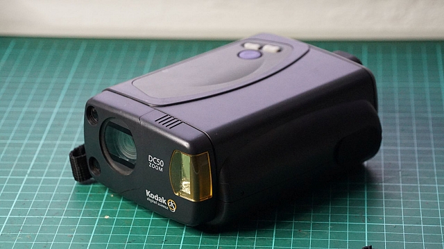
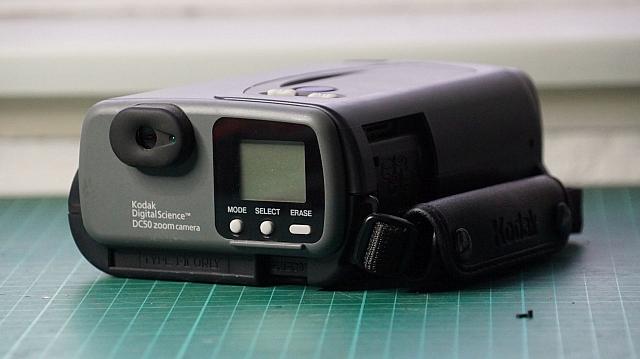
It actually has a PCMCIA slot on it! I had only learned recently that PCMCIA cards came as 'storage' modules. I thought they were all peripheral cards (network, modem) or IDE interfaces but hadn't realised that they came as sealed storage. It turns out the camera also has 1-Megabyte of internal storage. Seems that it's also 'FUL'! I wonder whats on there?
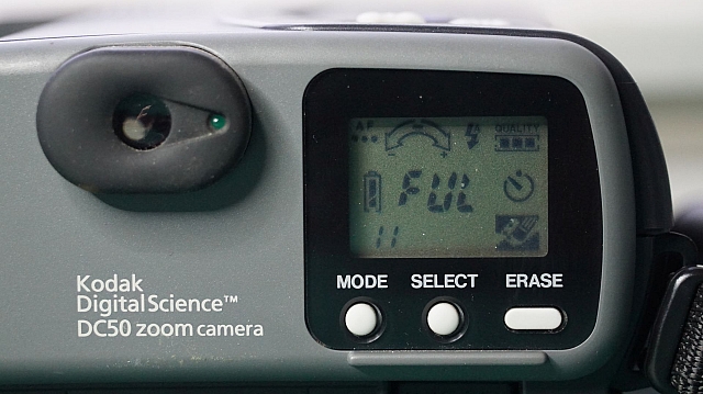
I had no cable and no way to get the data off, so I went and found my own media for it.
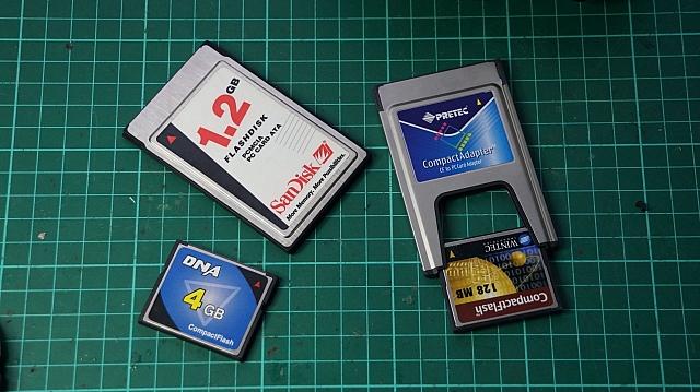
Turns out I had picked up a 1.2gb sealed PCMCIA 'ATA' Card in Malaysia (actually, I still need to write up Malaysia!), but this card was way too big for this camera. At the same time I'd also picked up a PCMCIA-CF adapter with a 4GB card in it, but that was also way too big... I rummaged around in my desk draw and grabbed the nearest/smallest CF card I could find: 128mb.
It happily started taking photos! On high resolution, the card can store ~760 photos. It just says 999 when I set it to medium or lower. After getting carried away snapping around the apartment, I quickly realised I had no USB CF card readers! Not to worry, I had enough old Windows 9x laptops, and could read the card via the PCMCIA adapter I was using in the camera to store the photos. This all worked fine... the card appeared in my computer, but the images were in KDC format? Turns out Irfanview can read these, so I needed to get them to my main PC.
The laptop had a USB port, but Windows 98 First Edition didn't have the drivers. You'll find that the standard NUSB33e drivers wont work. Instead, follow the instructions here. You'll have to install the unofficial Service Pack and then the USB drivers. All worked perfectly!
Once the files were on the USB, I moved them to my main PC.... here's the end result!
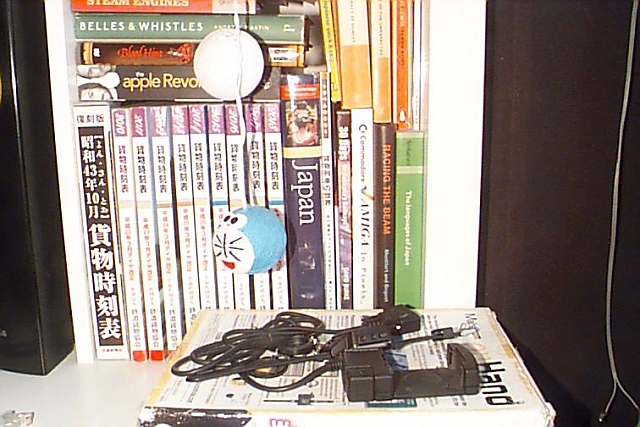
It works perfectly. 64kb of JPEG goodness... I wonder if IrfanView is trashing the quality of if that is just it... I'll take this on the weekend taking photos of the neighbourhood.
Internal Storage and Serial Transfers
Check this site out: It's the Japanese Kodak site for the DC50 serial cable and it's still online? Of course, you can't purchase from it and the picture doesn't help much. Tinker North West seems to also have a cable available... but I don't feel like paying real dollars for this thing. Turns out the pinouts are readily available (over here too.) The cable looks oddly familiar... I wonder if my weird Video plugs fit? Nup... one extra pin...
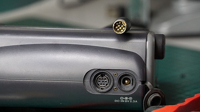
Wait... is that a Macintosh Serial plug? More rummaging in the drawer and... magic! Let's rig up a cable...
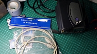
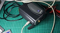
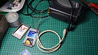
The wiring of the serial cable I had is as follows: 1 = brown, 2 = red, 3 = orange, 4 = yellow, 5 = green, 6 = blue, 7 = purple, 8 = black. Meanwhile the other end is a little controversial. DB-9 serial ports are easy to understand. But if you look here, they recommend RXD to RXD and the same with TXD? That kind of straight-through wiring really should not work. I have previously gone nuts trying to work out the difference between DTE and DCE here, and so didn't want to make the same mistakes again.
All Pinouts seem to have a wiring plan that's crossed over. That makes a lot more sense... but of course, the internet prevails. Back at Christophe Jacquet — Retro-digital photography: using the Kodak DC50, Christophe mentions that his minimal 'straight-through' cable worked perfectly? Maybe the pinout of the camera plug is wrong... i.e. they're mention RXD as the RXD of the computer, and it's actually TXD on the camera side? Let's just build it and see what happens... (Update: The cable needs RXD and TXD swapped. Build is as per this link!)
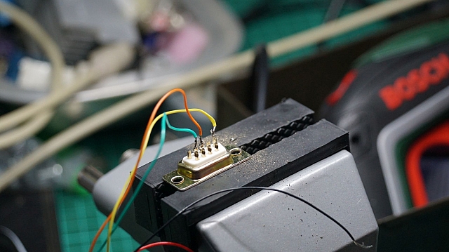
Ok... I have a cable... now software? Supposedly I need Kodak EasyShare, but that may be too new. Christophe links to Picture Transfer, but that link is dead... the Web Archive saves us again, but the binary isn't available! Grrrr... There's a newer version here of EasyShare, but I have no idea if that'll work. UPDATE: I found the software! (I'll come back to this soon.)
Open Source
Of course, there's a whole sub-culture in Linux regarding camera connectivity. The DC50 seems to be left out though. They mention that it uses standard serial transfer, and that the section will relate to that. But then the next area they say they'll add the documentation in a future HOWTO... but never got around to it?
Either way, that reference to kdcpi is a good hint. Fortunately, Tucows has saved it for future prosperity. Downloading it, one will find it's just a perl script. Three of the files are prepended with DC50... Let's do this! Perl is easy to set up on Windows (I used ActivePerl), with the script open in seconds...
C:\kdcpi-0.0.3>kdcpi.pl
Can't locate DC50.pm in @INC (you may need to install the DC50 module) (@INC contains: C:/Perl64/site/lib C:/Perl64/lib) at C:\kdcpi-0.0.3\kdcpi.pl line 32.
BEGIN failed--compilation aborted at C:\kdcpi-0.0.3\kdcpi.pl line 32.
First error... include libraries... I then copied all the files starting with DC into C:\Perl64\lib.
C:\kdcpi-0.0.3>kdcpi.pl
usage:
  C:\kdcpi-0.0.3\kdcpi.pl camera port speed command [ command arguments ]
Ok... nice, what are the commands? Looking at the source...
  print STDERR "$0: unkown command\n";
  print STDERR "implemented commands:\n";
  print STDERR "  dumpthumb - downloads thumbnails from the camera\n";
  print STDERR "  dump      - downloads picture(s) from the camera\n";
  print STDERR "  delete    - deletes picture(s) from the camera\n";
  print STDERR "  status    - displays the cameras status\n\n";
  print STDERR "  list      - lists name and sizes of pictures in the camera\n\n";
  print STDERR "  snap      - takes a picture\n\n";
  print STDERR "  set       - sets information about the camera\n\n";
If we type in a shit command, we'll get the list above... but we can just see it anyway.. so... list?
C:\kdcpi-0.0.3>kdcpi.pl DC50 COM1 115200 list
If you know information about the DC50 file format, please mail
bhirt@berkhirt.com and I will work on supporting it.
Access is denied.
Terminating on signal SIGINT(2)
Access is denied? A little bit of debugging proved that the following line of perl is problematic:
system("stty raw -parenb -parodd -onlcr -iexten -echonl -noflsh -tostop -echoprt -ixoff -olcuc -ocrnl -onocr -onlret -ofill -ofdel -echo -echoe -echok -echoctl -echoke min 255 time 5 cs8 9600 < $tty");
Hahaha... that's not even available on Windows. I'll continue this once I've spooled up an aging Linux laptop.
KODAK Picture Transfer Application
So, it does exist and it works. As mentioned in the update above, I found the application... I just don't trust the sites I downloaded it from. Anyway, that's why it's available here. With this, you'll need a Windows 9x vintage PC or Virtual Machine. I chose the latter....
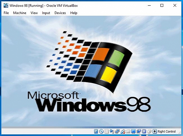
It needed a serial port. Mapping hte USB Serial port as a standard COM1 wouldn't be found in Windows 98. I therefore chose to feed the usb device to the VM and then gave it the driver here.
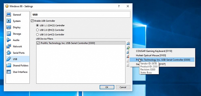
Note that I couldn't get file sharing to work... you'll get this if you try to network and share with an SMB1 device:
C:\Users\Steven>net use \\192.168.1.4
System error 384 has occurred.

You can't connect to the file share because it's not secure. This share requires the obsolete SMB1 protocol, which is unsafe and could expose your system to attack.
Your system requires SMB2 or higher. For more info on resolving this issue, see: https://go.microsoft.com/fwlink/?linkid=852747
So I used Fenix as a webserver after installing the latest Opera from oldversion.com. From there, we had connectivity! The next goal was to download and install the Kodak software.
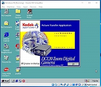
Oh golly... why does everything say DC120? I don't have that model! Please ... please ... please work!
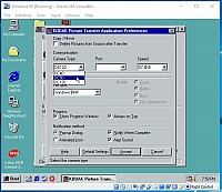
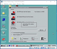
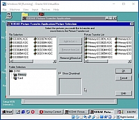
Oh yeah! There's the 11 photos we were advised of from the back of the camera! Let's download them! (Nice that the app happily translates them to Bitmap for us!)
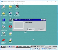
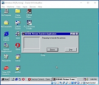
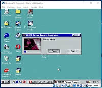
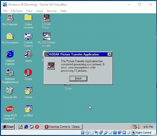
And we're done! What did we download?
A lovely cat that looks like a cow. I win!
As per usual, it was another trip to Canberra via Cootamundra over the Christmas break. This time was a little different though... no holiday pay! I'm now a contractor! Regardless, both trains and family needed to be visited! The trip started at the usual sparrow-fart-o'clock and I caught the up Albury somewhere along the parallel stretches of highway and railway.

Awful lighting and a bad angle... I then totally missed the southbound XPT. I heard it growling through as I was filling the tank at a service station. From there, there was nothing on the rails. I grabbed a pie or two at Culcairn, but wasn't impressed at all... maybe the baker had been in a hurry. The first sign of movement was the southbound Harefield shuttle prepped at Junee. Of course... just as I approached it started to head south!


I then whipped the MR-2 around and got to the favourite position... The train had crawled out of Junee, but nearly beat me up the hill? Nice effort!


Crap lighting... the clouds really didn't want to play ball. From there it was more quiet rails. After checking in at the usual motel I was told the pool had a leak and had been emptied. The MR-2 hadn't had aircon for a few years, but it was ~35 outside and I was looking forward to a swim. Instead it was aircon in the motel room whilst I got a bit of work done.
The rest of the afternoon was spent with good friends from Cootamundra. Thanks Laurie for driving and knowing all the good spots to get the SSR grain rake! The proof is as follows...


I hear they're now calling the Qube QBX locomotives 'Chiko Rolls'... pretty hilarious actually. Two separate consists came through in quick succession! We then retired for the afternoon before a great meal at the local.
The next morning was spent getting in front of a northbound SCT service. It'd beaten me out of Cootamundra, but I got it before Yass. I hereby dedicate the next block of photos to my favourite location: Yass Junction Station.


I expected to then just dawdle back into Canberra... but instead found the SCT pulling to a halt in the station area. The drivers then inspected all axles... they must've triggered a sensor somewhere and been told to check if anything was actually wrong? They held there for 10 minutes and then pushed off again.


That was it for the trip towards Canberra. Whilst there I swapped the AW11 MR2 for a 2015 ZRE182R Corolla and, well, it's not the pocket rocket that the MR2 was, but it's got enough of it's character and so much more comfort! The return trip was therefore a quick one, going through to Melbourne in one day.


There's the 'rolla at Jindalee. Collecting rock-chips on the bonnet that I wouldn't realised until I washed it in Melbourne. Damnit. Anyhoo... on the way back, QBXs were seen bolting into Junee...


And then the XPT passed a CK grain at Gerogery?


And that was another wrap. Home just in time to catch the Air Asia X flight to KL the next morning!
Picked up this awesome external SCSI HDD enclosure last week but was perplexed by the cable. There's an ultra-tiny plug on one end and a standard-sized external 68-pin plug on the other. So far I've only seen this plug on internal cables and didn't know it was built in an external format also.
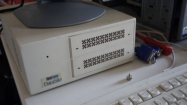
I was already in trouble. All of my standard ISA or PCI cards are either Centronics, DB25 or ultra-tiny plug and the only card I have with a full-width 68-pin external socket is a 64-bit PCI card!
The last motherboard I had with 64-bit PCI slots was the Apple G4 Graphite and that's long gone. I realised I could plug the cable into the internal side of the card... but that wasn't optimal!
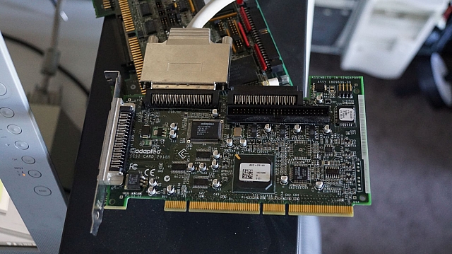
A quick google then lead me to understand that 64-bit cards are backwards compatible with 32-bit slots! Supposedly there's an 'enable' pin on the extra 64-bit edge connector section where, if not brought down, the cards are expected to work in 32-bit mode!
So I lined it up...
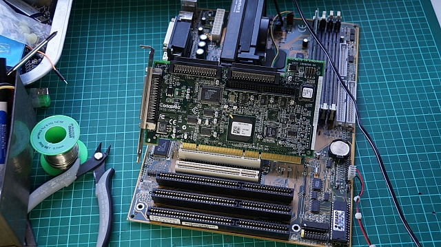
And plugged it in...
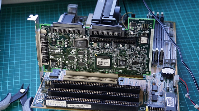
And the world was a happier place! The drives came online (with extended IDs 14 and 15) and their contents happily displayed. They turned out to be a RAID pair of NT Server NTFS drives with home directories from an old Radio/TV company. Very random stuff in here!? Is data archeology a thing!?
So, this ended up being a bigger hack than expected... but I'm happy with the result! I picked up this unit from eBay and hoped to use it as-is, but the motherboard wasn't healthy and Microchannel anything is impossible to find. I therefore replaced the guts with a DX2/66 motherboard! It all worked perfectly and I was happily playing games... but then I found a P166 at the markets and felt it was time for an upgrade.
Power Supplies
I picked up a Pico-ATX adapter on eBay rated at '120w' and had very little success with it. I could get it to boot without any cards... but as soon as I added anything on the ISA bus, let alone actual drives, I had zero action. Seems that it's just not up for the current required. I was also feeding it power from the internal 12v on the IBM's motherboard and this may have been overloading a single 12v rail.
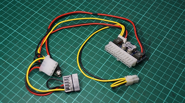
It also needed a floppy connector... seems that these are for mini-atx boards where floppies are a distant memory...

Thinking that it just needed more amperes... I mounted a new 12v supply inside the monitor housing...
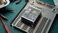
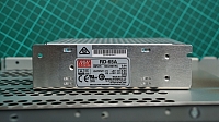

I grafted this onto the power rail to the front switch of the machine... it was rated at 110-240v, so there were no issues with step-downs...
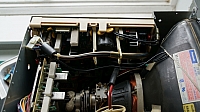
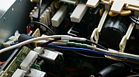

This then meant the front power led was no longer lighting up, as the internal power supply had no current draw... I had to then use a resistor and put it on the 5v output of the new supply.
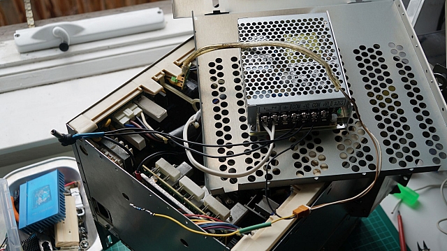
But... it still just didn't work... the actual Pico-ATX unit just wasn't up to the challenge of the old P166 motherboard! I then purchased the '160w' version off eBay, but it was EXACTLY THE SAME unit?
Slightly-larger ATX supply
I happened to be near an old PC shop in the city where I'd previously sourced a 'smaller' ATX power supply. Turns out they still had stock! I wasn't overly sure if it'd fit, but I was happy to have a spare in stock regardless. To my happiness, it fit perfectly!
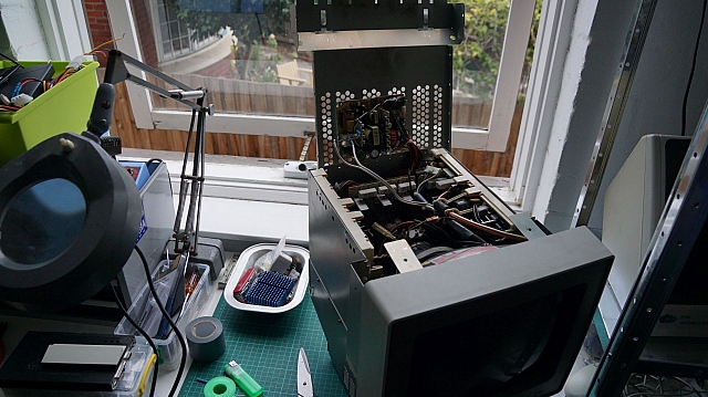
I mounted it under the lid, as per the previous power supply, and ran the 110v in (flicking the voltage selector switch!) from the main power supply. The ATX cable was then fed straight down the back into the motherboard 'compartment'. It booted and the machine was back to normal... this time with W98SE and more horses!
It all started by finding this beast on the footpath. I saw that it had two scart inputs and had to have it. I built an RGB cable for my MSX a long time back but have always been disappointed by its performance via a scart-to-HDMI converter. So, I set about testing and hooking it all up. Of course, it didn't have a remote, so I had to use an Arduino to translate another remote into the appropriate codes.
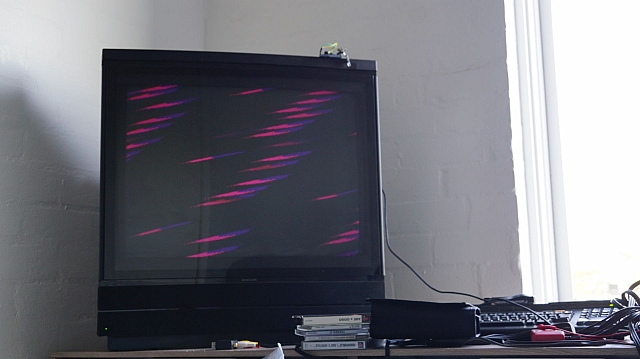
With access to all the menus, I started toying with values, but the picture from the MSX was still broken!
What can be configured?
Via the front main menu? Nothing. Via the service menu? A lot more. With my model, I had to pull off the back case and short the service pin header (I'd actually really like to just install a pushbutton switch onto that!)
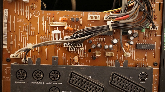
Once off, and with the TV on TV mode, use something metal to short those two pins in the middle that say Service Mode. You'll then get the following message on the TV...
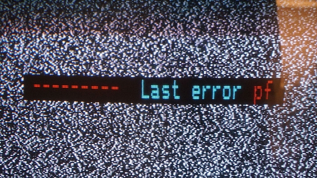
Last error was a pf? Sure was... I just pulled the plug... total power failure! Here's the other error descriptions...
| Code |
Description |
| No |
no error registered |
| PF |
Power Fail |
| 00 till FF |
Error address on the I2C bus |
| DF |
Data failure (maybe EEPROM 6IC6 on the cpu board defect) |
| 4E |
1/38IC6 Tuner & IF port expander |
| 84 |
1/38IC2 A2 Stereo decoder |
| 40 |
31IC7 NICAM stereo decoder |
| 42 |
41IC5 D/A converter for cut-off and drive |
| 22 |
37IC2 Teletext decoder |
| 8C |
13IC2 Deflection controller |
| 82 |
14IC1 Audio Controller |
| 86 |
14IC9 Video Controller (14IC9 means Board 14 Chip IC9) |
Anyway, using the arrow keys, you'll be able to configure the following settings. There's an awesome thread post here on BeoWorld from Die Bogener explaining all sorts of troubleshooting for the TV!
| Code |
My Default Value |
Description |
| Rdr |
50 |
Red drive |
| Gdr |
45 |
Green drive |
| Rcu |
28 |
Red cut off balance |
| Gcu |
29 |
Green cut off balance |
| BRI |
03 |
Brilliance Preset |
| COL |
03 |
Color Preset |
| Hfq |
37 |
Horizontal frequency |
| Hph |
35 |
Horizontal phase |
| Ham |
22 |
Horizontal amplitude |
| Vam |
29 |
Vertical amplitude |
| Vsc |
32 |
Vertical S-correction |
| Vsh |
30 |
Vertical shift for centering |
| Vli |
18 |
Vertical linearity |
| EWc |
05 |
EastWest corner |
| EWp |
1 |
EW parabola |
| EWt |
41 |
EW tilt |
With all these settings being adjusted (and then reverted) to no avail... I started to wonder if it wasn't a Japan vs. Australia thing... NTSC vs. PAL? Does the RGB signal have a 50hz/60hz rate or other 'remnants' from the units output? Is it Australia's fault for successfully implementing only one standard? (For once!)
Does RGB care about NTSC or PAL?
Wherever you read, you'll find hot debates over RGB and how the signal differs from a PAL or NTSC console. From what I understand, it's a NO. Any TV with SCART that is RGB capable will take an RGB signal from any device. Do correct me on this, thought!
Can My TV Decode NTSC?
Here's the service manual which points out the following difference between the PAL and PAL/SECAM versions...
Yeah, that's not just PAL/SECAM... it's PAL/SECAM/NTSC! But wait... the MSX works over Composite? Which has to be NTSC-J Composite? What gives?
Maybe it's my RGB Cable?
There's a good bit of information at this post regarding RGB cable issues and required voltages. Supposedly the SYNC signal on the SCART plug can just be fed Composite video, but it needs to be within tolerance. This also goes for the switching which declares what video format is expected on the SCART plug. So, after reading more on Sync for SCART , Sync Strippers and types of Sync from random consoles.. I ended up slightly more confused, but decided to rebuild my cable.
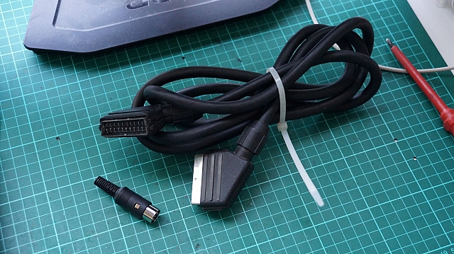
Thankfully, my junk box had a beautiful SCART-to-SCART cable... I didn't know these existed, but it makes total sense that they do. It's wired as a 'crossover' as the output from one machine needs to be fed to the input from another. I'll never be outputting via a SCART plug, so I decided this hefty cable would shield me nicely from interference and provide a great base for a proper RGB cable for the MSX.
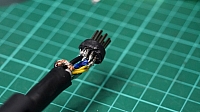
With the SCART pinout in one hand and the Japanese MSX RGB pinout, I set out to rebuild the cable... I hooked up the minimal wires: R,G,B and Sync + all their required grounds. This got me nowhere. So I then hooked up Ys to the 'output select' and I received a mis-coloured picture!
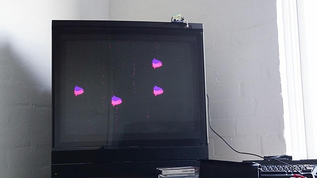
I quickly slapped spacebar... the fish are the screensaver for multemente on MSX...
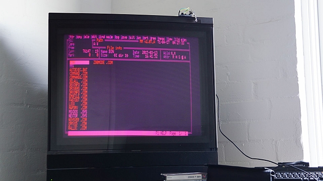
Oh right, I've swapped G and B around... wait... it's reading the RGB channels? But wait... if I then switch the TV to DVD... bang... wrong format!? Wait... this has worked all the time? I hadn't noticed the clearer picture... I'd just thought it was pulling composite over SCART... instead it was actually displaying the correct picture. For some reason, the TV is expecting a different format on V.Aux and that's where it's screwing up. RGB WORKS!
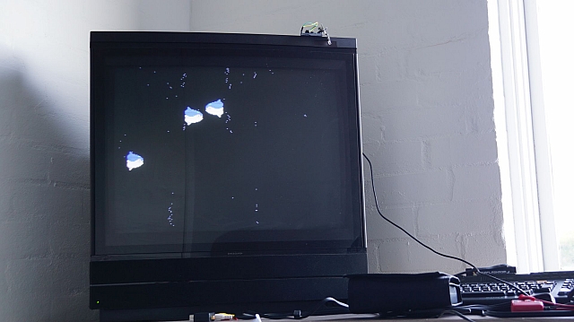
It turns out that, if you have your SCART-connected device turned ON, then the TV tries to switch to its input, even if you've selected the wrong input? Seems to be a bug? Or a problem with my TV configuration? The TV was configured as follows...
I set out to test: PS1 in AV1 and MSX in AV2. The PSX worked perfectly when the MSX was off and the TV was set to 'DVD' (which was the setting of AV1)...
But as soon as I turned on both consoles, the MSX would trigger the AV1 channel to distort. Switching to V.AUX (or AV2, where the MSX was plugged in) worked! So, all this time... everything was working, I just didn't understand (still don't!) how the inputs work on the MX 7000. All I know is that you should only have one input powered up at one time! So, here's some RGB goodness...
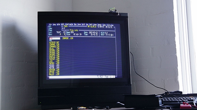
SCART cable quality!
This has all occurred because I saw the quality of the original SCART cable and thought it was composite! Here is the old cable plugged back in again. Note that it's just 8-core wire, no shielding... so the quality sorta makes sense...
Compared to the shots above, you can see the distortion. But I admit, it's really hard to take a proper photo of a CRT! So.. it was nice to build a real cable.. although, dealing with the gauge of wire was a little tough. It seriously had a mind of its own!
Both units need an overhaul
Whilst doing all this research, I found notes on both items for overhauls! Seems that an urgent capacitor replacement should be carried out on any Japanese MSX with a specific daughterboard. Also, the BeoVision MX Service Guide indicates a whole bunch of capacitors that could be life-expired!


 Melbourne BG SCS Train Timetable


