


 Melbourne BG SCS Train Timetable


DCC Booster Complete
Ladies and Gentlemen,
I am proud to finally announce that the Booster has been completed and tested.
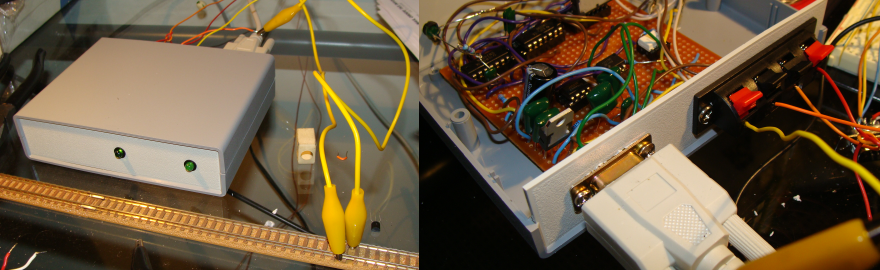
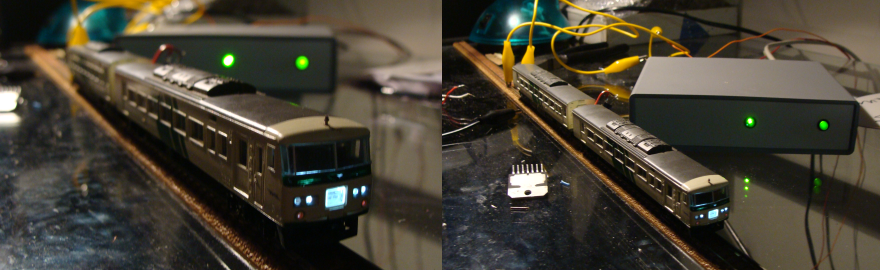
The final design incorporates the following features:
- Short Circuit Protection with a ~6sec timeout when short detected.
- Two segments per booster rated at 2-3Amp each.
- These can be combined for a total output of ~5Amp.
- Status LEDs to indicate power output on each segment and also overload/short detection on each segment.
- Second Serial Port (DB9) on the rear panel to allow data connection to another booster.
A typical setup of the Booster would be as follows:
The Booster shown above was built in a readily-available Project Box and the next one built will probably not use the same model. I'll be going to the store on the weekend to see exactly what is available as the box used is a little larger than what is really required. Either way, if you still wanted one of these, now is the time to contact me.
Final PCB Board Complete!
Well, Silver Circuits manufactured and delivered my PCB much much quicker than expected and I'm not complaining!
And, last night, after a rush of construction... I couldn't get the board to work... The 'trip' sensors were permanently active! After a 30 minute stare at the circuit design today I'd realised I'd viewed an older circuit schematic when designing the PCB and had put the inputs to the LM339 the wrong way around!
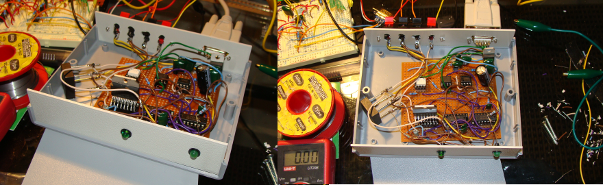
After a quick test to correct this I had the booster operational.
Unfortunately this now means that all boards in this initial run are defective, but I have devised a way to correct the issue without too much hacking. A small veroboard piggy-backed on has allowed me to correct the inputs to the IC.
I was very much relieved once it was all operational. I now need to get the final components (you can see a dodgy-hack of resistors wired on) and the heatsinks in place. Then I'll need to find a neater box to mount it all in and all should be set to go.
PCB Design Complete
Well, after a long fight of finding appropriate software and then design I've finally sent off the final (if not entirely messy) design to the manufacturers...
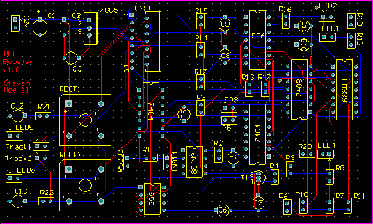
Sure, it's not as small as I would have liked... but it's all set in stone now. I should see 8pcs on my doorstep in around a fortnight and then I can finally produce a finished product.
I can't wait actually... Last weekend I tested the final prototype on my own layout... which really only allows for around 3 trains running (one on a branch, one stuck in a siding and one on the main) and my battery ran out on the laptop before I had a chance to fully test it all out... either way, the quick test ran perfectly on all accounts:
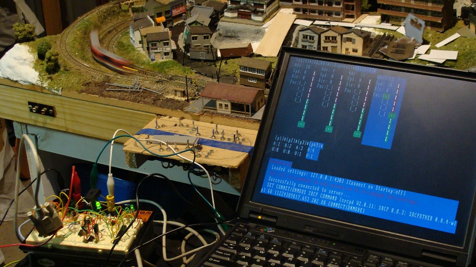
I also purchased two DCC Accessory Decoders from eBay. I coded those in to trainControl (you'll see a few little squares above the console messages and below the train throttles) and they work great. Unfortunately they cannot be wired directly to the Kato UniTrack points (you'll need to wire a few relays in between) but I'm told work well on the Peco points. I didn't get to test them at the time.
The DCC Accessory Decoders did require me to do a bit of fine tuning on the Booster circuit though; it turns out they suck quite a bit of current on power-up to charge their little capacitors. This meant that the initial current draw on the booster was exceeding the trip circuit and the whole system would not power on.
After a little help the 1K2 resistor providing the op-amp comparison voltage was incremented to a 1K4 and everything worked fine.
This made me realise that the circuit will have different requirements for different layouts and so the final design will now incorporate a trimpot (initially set to 1K4) that can be user adjustable [but WILL void warranty] for 'expert users' to adjust.
Anyway... the work continues... everything is now set. I'm quite proud of the entire system and I can't wait to see the final circuit boards!
UPDATE: The boards are already done and on their way (priority) to me... thanks to Silver Circuits!
DCC Booster Prototype Mark II
Ok, hot off the development floor is the Booster Prototype 2.
This now includes short-circuit protection! The final design will have 2 outputs (for two separate segments of track) at 3 Amp each (depending on power supply capabilities.) There are also now 4 status LEDs (Supply Power, Data, Overload, Track Power/Data)... More to come as I finalise the circuit board design.
trainControl evolves…
After a few more days of work the trainControl application has evolved further:
Notable features:
- Loading and saving of trains/connection config
- Resizable
- Add/Delete trains via interface
- Connect/Disconnect on the fly
Still more to go... but very functional now... Download the source here. Of course, be warned! ... The source is constantly being updated by me and may DESTROY your computer. I've also considered the next challenge on this project... Handheld control via a GamePark GP2x.
trainControl v0.1 created!
After 3 days of coding/learning/coding-again I managed to whip together a fairly usable *nix console application to control the DCC System.
It is a client for the srcpd service mentioned previously and can control any number of trains.
There's still a fair bit of work to do on it... dynamically resizing windows, mouse input, etc... but I thought I'd post to show some progress.
If anyone is interested the source is here and can be compiled with gcc -o tc main.c -lncurses -lform -lpanel
...work continues...
Controlling the Booster from Linux
After losing the source code to my DCC Throttle application I decided it was time to get the whole system controlled from Linux (or, in my case, Debian.) I'd known that the DDW Server I'd been using was based off srcpd and that they were more-or-less compatible.
After a lot of tinkering (making sure libraries/compilers/etc... were installed) I finally got srcpd compiled and running.
There is a nice web-app to create the required configuration file which is then thrown in /usr/local/etc/ or can also sit in the same directory as long as you specify it.
It seems that you need to make sure that the 'NRMA/DCC Translation Table' is set to '1'. I have a copy of my configuration file here.
Right, now that the server was running I grabbed Telnet and connected to localhost:4303. I attempted to use the same set of commands as I had with DCCThrottle but to no avail... it turns out the version of srcpd I had installed was based on the 0.8.3 srcp specification... much had changed.
Instead of reading up on what I should be doing differently I connected up dtcltiny 0.8.2.
After a lot of tinkering with compilation/libraries/etc... I finally got it installed. On debian make sure you have qt3-apps-dev and libqt3-compat-headers installed... do this with apt-get. Anyway... I'd done all this on a spare Thinkpad 600E I had lying around (PII 266mhz 256mb RAM) and I'd had a few issues with lag once it was up. I'd turn the headlights off on the control panel and my Twilight Express locomotive would then go dark around 1.5 seconds later. After turning off nearly all debug output I had a relatively stable system... but it does need a lot more investigation.
The next trick will be to investigate building a client on the console... I don't need fancy Xorg to get a gui and an ncurses console app should do. I saw rcsh and rcman and the rest, but python isn't my friend... although it'd be a nice opportunity to learn.
Anyway... all of this was a great learning experience... and I was quite impressed that my old notebook handled Debian and got the locos moving.
Prototype Booster Complete!
Well... after a night of work (and using my breadboard version as basis) of soldering and drilling I have a prototype! I've used off-the-shelf components to house the board and everything fits nicely... secure... and works perfectly.
The next version will have an override switch (since the current version will only activate when there is data on the serial port) to allow power all the time.
Now is time to use this version as a test for how many amps it can push out... note I'm still using my computer power supply (which is still powering this machine I'm surfing on!) and all is well.
Finally... The going price for one of these will be AUD$65.00.
Anyone wanting one can leave a comment on this post or email me at stevenhoefel at hotmail dot com.
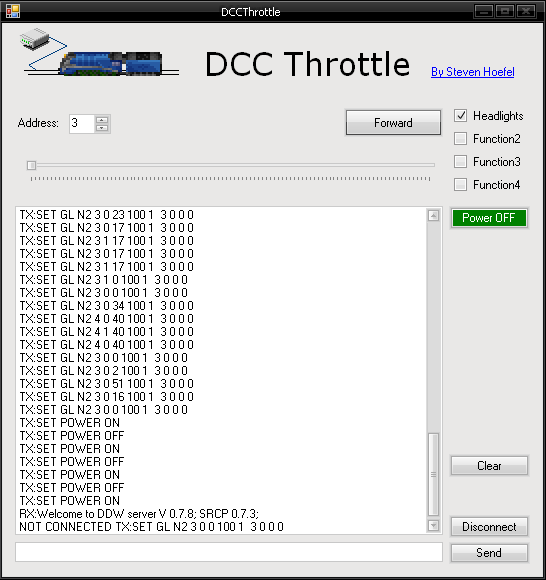
I've also written a new client app... very basic... controls the train that you specify.
Researching a DCC booster circuit and DCC computer control
Ok, after a miriad of attempts to control my model railroads with computers (parallel port to relays, voltage controls, etc...) I decided it was time to go to DCC... I mean... why not use the rails as a data bus and have all the logic inside the locomotives themselves. I had decided that all the european command stations were too expensive and that I would do as some of the references below have done and just use my computer to push out the 1's and 0's. Anyway, after a lot of trial and error I have a working prototype... but stay tuned for something more production ready.
For starters, here are some good references on homegrown DCC Boosters:
- The DCC Wiki
- Michael Brandt's Site on DCC
- Rod Murgatroyd's Booster (And other circuits)
- Haba's Booster
- Mr Paisley's Booster
After searching online electronic stores for parts, I had noticed that there were two basic circuits in use. One used the L298 H Bridge and the other the LMD18200. As I'd browsed across Michael Brandt's site first, I'd realised that it was only necessary to connect a booster to the computer (and Haba's site confirmed this). Although I'd purchased all the components to make the Parallel port logic board, I've still never actually constructed it since it was much easier to just go direct to the COM1 (and also skip all the assembler programming!).
One weekend-long of wiring and re-wiring produced this... It's recommended to build anything like this first on a breadboard as you get the opportunity to just rip it all back out again when you make mistakes... and after a lot of cooked components and other issues... I finally got it all to work. The circuit uses a 12vAC input but I just skipped the initial AC-DC regulator and used the 12vDC from my computer's power supply. This currently allows around 8vDC to the engine and so I'll be upgrading to something closer to 18vDC input when I get the chance... For now, and it's great for testing, it's better to have lower voltages.
Next, Software...
There are a few options here... many in German and many in Linux. I'd found DDL and realised this was the way to go. It is what Haba had been running and therefore must work. I had severe issues compiling it on debian since the code was old and am still not across C/C++ enough to have gotten it going. I then found the binaries and managed to get something running, although couldn't successfully get a connection. (This was also whilst I was using Rod's circuit and so there could well have been too many variables...)
I then hit gold with DDW (DDL for Windows!). I had a few initial problems working out which port COM1 was and then why there was no action... but once my booster was complete and connected everything just started going... I realised that the server alone is no good... it wont send out data without a client connected... client of choice being RailyPlan v2.0 found on theDDW download page.
Now, I'd bought 2 Hornby R8215 Decoders and, based on forums read online, there seems to have been NRMA DCC compatability issues... Let me tell you that these things are gold. They are tiny, cheap and reliable. I've cooked one quite well and it keeps going... it has even emitted the usual burning-silicon smell a few times (when the motor has shorted) and keeps going. The only issue I've had is that the wires unsolder themselves when it gets tooooo hot. :)
The first decoder was installed in my old-reliable German DB loco (model unknown) and it was too easy. Plastic chassis, minimal wiring... simply spliced in. The decoder defaulted to Address '3' and I had it running in no time. Had no headlights or anything else to wire up, so there was no test of functions, etc... here.
This engine ended up being the old-reliable for a very long time for testing purposes of software, etc... that I was about to write. I believe I'm about to realise how easy this first loco install was compared to the little space that exists in Japanese n-scale engines.
I'm currently in the process of Decoder-ing up my Odoriko 5-Car series and will post again once I have the final story.
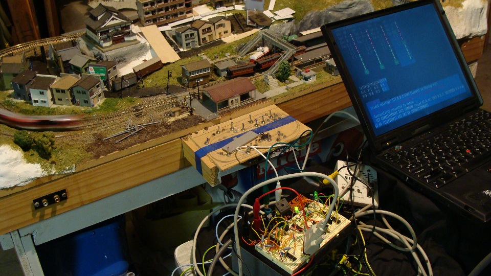
What a mess... you can see the breadboard up the back being powered by the computer power supply under the desk and my straight run of track.
Random Photos
Search
Tags
Links - Click for details
- Abandoned Rails (Japan)
- AIRLINE (Shinkansen Photography)
- Akihabara Station
- annexpressのブログ
- Australian Model Railway Magazine
- DCC普及協会ホームページ (Japanese DCC)
- Dead Section (Japanese Track Diagrams)
- Delicious Things (Japanese N Scale DCC)
- Densha Wotorou
- Digital Direct for Windows (DCC Server)
- Don's Dream World – AMAZING N Scale Japanese Layout
- Hatena::Diary
- Japanese N-Scale Modeling Forum
- JR Chiisai
- Kaz-T's blog レインボーライン (Rainbow Line)
- LED Resitance Calculator
- Masioka
- Poppondetta Blog
- RailFan Magazine, Japan
- Railmind
- Railway Travelers' Room
- Serenity Valley
- Shashinka Ichiban
- Shuzuku
- Sumida Crossing
- The next station is…
- Tomix N Gauge Track and Japanese N Gauge Trains
- TT Forums (Transport Tycoon Deluxe)
- 名鉄尾西線の貨物列車 (Nagoya: Meitetsu Freight)
- 日本型Nゲージ DCC改造例のご紹介 (Okiraku DCC)
- 泰 茅 轍 道 (Taichi Railway)
- 箱庭登山鉄道製作記 (Hakone-Tozan Layout Blog)
Archive
- April 2026
- March 2026
- February 2026
- January 2026
- November 2025
- October 2025
- September 2025
- August 2025
- July 2025
- June 2025
- February 2025
- January 2025
- November 2024
- September 2024
- August 2024
- July 2024
- June 2024
- May 2024
- April 2024
- March 2024
- February 2024
- December 2023
- October 2023
- September 2023
- August 2023
- July 2023
- June 2023
- May 2023
- April 2023
- March 2023
- December 2022
- November 2022
- October 2022
- April 2022
- March 2022
- February 2022
- January 2022
- December 2021
- November 2021
- September 2021
- August 2021
- July 2021
- May 2021
- March 2021
- February 2021
- January 2021
- October 2020
- September 2020
- August 2020
- July 2020
- June 2020
- May 2020
- April 2020
- March 2020
- January 2020
- December 2019
- November 2019
- October 2019
- September 2019
- August 2019
- July 2019
- June 2019
- April 2019
- March 2019
- February 2019
- January 2019
- December 2018
- November 2018
- October 2018
- September 2018
- August 2018
- July 2018
- June 2018
- May 2018
- April 2018
- March 2018
- January 2018
- December 2017
- November 2017
- October 2017
- September 2017
- August 2017
- July 2017
- June 2017
- May 2017
- March 2017
- February 2017
- January 2017
- December 2016
- November 2016
- October 2016
- September 2016
- August 2016
- July 2016
- June 2016
- May 2016
- February 2016
- November 2015
- October 2015
- September 2015
- August 2015
- July 2015
- June 2015
- May 2015
- April 2015
- March 2015
- February 2015
- January 2015
- December 2014
- November 2014
- August 2014
- July 2014
- May 2014
- April 2014
- March 2014
- December 2013
- November 2013
- October 2013
- June 2013
- August 2012
- April 2012
- March 2012
- February 2012
- November 2011
- October 2011
- September 2011
- July 2011
- June 2011
- May 2011
- April 2011
- March 2011
- February 2011
- January 2011
- December 2010
- November 2010
- October 2010
- September 2010
- August 2010
- June 2010
- May 2010
- April 2010
- March 2010
- February 2010
- January 2010
- December 2009
- November 2009
- October 2009
- August 2009
- January 2009
- December 2008
- November 2008
- October 2008
- September 2008
- July 2008