


 Melbourne BG SCS Train Timetable


IBM 45U0018 POS Keyboard
I saw this unit on eBay and couldn't resist. It really did remind me of the department store POS keyboards and I remember them being clicky. I checked the photos on the auction and saw that it had a non-standard socket and no cable included. You can download the drivers/configuration-utility here.
The main keys are fixed, but the surrounding keys have optional translucent key 'covers' where inserts have been placed for special functions. Some of them even cover standard keyboard keys.
But yeah, back to the socket, and do excuse the photo...
It's very similar to a standard IDC Header, but in-set which makes it really difficult to use anything other than IBM's proprietary cables. After a lot of googling, I found that there's both a USB and PS/2 cable version available.
Unfortunately, these weren't actually available anywhere... and if they were, the cost was out of control. It seems that these keyboards could also just dock onto the POS system above the till, so it's possible that the cable was only required if you wanted to mount the keyboard elsewhere. Anyway, a cable would be too easy... I'm sure we can work this out!
What does it look like on the inside?
With the hunch that the port supported PS/2 and USB, the keyboard was opened to work out the pinout. Opening it was actually very easy with just 6 small screws on the back. A large plate comes off and then there's just a bit of foil-cardboard shielding over the main circuit board.
Inside, of note, were a TUSB2046B IC and a STM32F103VBT6 Microcontroller with V0326_PF.bin programmed into it. The first IC happens to be the brains for a USB 4-port hub and provided a huge hint for determining the unit's wiring. I started tracing along the pins and the table below is the result.
Note that, when looking at the back of the keyboard into the socket when the keyboard is UPSIDE-DOWN on a flat surface, I've started Pin 1 from the top-right, with pin 6 then being top-left, pin 7 bottom-right and pin 12 bottom-left. This turned out to be silly as all the wires are in vertical pairs. Note this has been updated from the great resource at sharktastica.
| Pin # | Connected To | Notes | USB Cable |
|---|---|---|---|
| 1 | Pin 1 of T-46 aka TPS73633DBV | Voltage supply for the power regulator. Must be 5v! | Pin 1 - Red |
| 2 | Pin 1 of TUSB2046B | DP0 = Root port USB differential data plus. DP0 paired with DM0 constitutes the upstream USB port. | Pin 3 - Green |
| 3 | NC? | ||
| 4 | Pin 3 (or 6) of U4 | U4 is not populated. | |
| 5 | Pin 64 (PC7) of STM32F103VBT6 Microcontroller | PS/2 Keyboard Clock | |
| 6 | Pin 48 (PB11) of STM32F103VBT6 Microcontroller | PS/2 Mouse Clock | |
| 7 | GND | Pin 4 - Black | |
| 8 | Pin 2 of TUSB2046B | DMO = Root port USB differential data minus. DM0 paired with DP0 constitutes the upstream USB port. | Pin 2 - White |
| 9 | NC? | ||
| 10 | Pin 2 (or 7) of U4 | U4 is not populated. | |
| 11 | Pin 66 (PC9) of STM32F103VBT6 Microcontroller | PS/2 Keyboard Data | |
| 12 | Pin 52 (PB13) of STM32F103VBT6 Microcontroller | PS/2 Mouse Data |
Ok, so that's easy for the USB connection.. just wire the 'upstream' pins, +5v and GND into a spare USB cable. The other 2-pair of wires which run into the Microcontroller must be for the PS/2 mouse and keyboard? I wonder which is clock and which is data? There are plenty of images online showing microcontroller-to-PS/2-port hookups, so I'll try that after USB.
Hooking Up USB
USB cables contain 4 wires. First you need two wires for a very standard 5v DC rail and then you need two more wires to transmit and receive data. As you can see from the table above, we have all of these already mapped out. This was all very straight-forward thanks to the documentation for the TUSB2046B USB Root Hub IC. I grabbed a bunch of spare parts from the box'o'junk and started wiring something together. The USB cables I first tried to use happened to be power-only? No data lines! No wonder someone else threw them out.
Too short anyway! So instead, I remembered I had a mini USB socket in another tray'o'junk and set to wiring that up...
I plugged it into my RasPi 400 and it evicted all USB devices...
Sep  2 17:04:30 raspberrypi kernel: [63187.047153] usb usb2-port1: over-current change #1
Sep  2 17:04:30 raspberrypi kernel: [63187.202027] usb 1-1-port1: over-current change #1
Sep  2 17:04:31 raspberrypi kernel: [63187.278524] usb usb2-port2: over-current change #1
Sep  2 17:04:31 raspberrypi kernel: [63187.438880] usb 1-1-port2: over-current change #1
Sep  2 17:04:31 raspberrypi kernel: [63187.518607] usb usb2-port3: over-current change #1
Sep  2 17:04:31 raspberrypi kernel: [63187.678902] usb 1-1-port3: over-current change #1
Sep  2 17:04:31 raspberrypi kernel: [63187.758546] usb usb2-port4: over-current change #1
Sep  2 17:04:31 raspberrypi kernel: [63187.918864] usb 1-1-port4: over-current change #1
Sep  2 17:04:31 raspberrypi kernel: [63187.998562] usb usb2-port1: over-current change #2
Sep  2 17:04:32 raspberrypi kernel: [63188.238478] usb usb2-port2: over-current change #2
Sep  2 17:04:32 raspberrypi kernel: [63188.478480] usb usb2-port3: over-current change #2
Sep  2 17:04:32 raspberrypi kernel: [63188.718503] usb usb2-port4: over-current change #2
Sep  2 17:04:32 raspberrypi kernel: [63188.890074] usb 1-1-port1: over-current change #2
Ooops! Why am I chewing too much power? I google'd around and couldn't find an easy solution to inject my own power, as all answers indicated VCC needed to stay connected. Looking at my wiring again, I realised that this error was bound to happen as I'd wired the polarity around the wrong way! So, after correcting that...
Sep  2 18:44:47 raspberrypi kernel: [69203.309095] usb 1-1.3: new full-speed USB device number 9 using xhci_hcd
Sep  2 18:44:47 raspberrypi kernel: [69203.443182] usb 1-1.3: New USB device found, idVendor=0451, idProduct=2046, bcdDevice= 1.25
Sep  2 18:44:47 raspberrypi kernel: [69203.443193] usb 1-1.3: New USB device strings: Mfr=0, Product=0, SerialNumber=0
Sep  2 18:44:47 raspberrypi kernel: [69203.449815] hub 1-1.3:1.0: USB hub found
Sep  2 18:44:47 raspberrypi kernel: [69203.452677] hub 1-1.3:1.0: 4 ports detected
Sep  2 18:44:47 raspberrypi kernel: [69203.779047] usb 1-1.3.4: new full-speed USB device number 10 using xhci_hcd
Sep  2 18:44:47 raspberrypi kernel: [69203.922725] usb 1-1.3.4: New USB device found, idVendor=04b3, idProduct=4604, bcdDevice= 3.26
Sep  2 18:44:47 raspberrypi kernel: [69203.922734] usb 1-1.3.4: New USB device strings: Mfr=1, Product=2, SerialNumber=3
Sep  2 18:44:47 raspberrypi kernel: [69203.922741] usb 1-1.3.4: Product: IBM Retail USB Alphanumeric POS Keyboard
Sep  2 18:44:47 raspberrypi kernel: [69203.922747] usb 1-1.3.4: Manufacturer: (c) Copyright IBM Corp. 2008
Sep  2 18:44:47 raspberrypi kernel: [69203.922752] usb 1-1.3.4: SerialNumber: 44T4011-200811231006420977000036
Sep  2 18:44:47 raspberrypi kernel: [69203.935428] input: (c) Copyright IBM Corp. 2008 IBM Retail USB Alphanumeric POS Keyboard                                      as /devices/platform/scb/fd500000.pcie/pci0000:00/0000:00:00.0/0000:01:00.0/usb1/1-1/1-1.3/1-1.3.4/1-1.3.4:1.0/0003:04B3:4604.000D/input/input18
Sep  2 18:44:47 raspberrypi kernel: [69204.000545] hid-generic 0003:04B3:4604.000D: input,hidraw4: USB HID v1.00 Keyboard [(c) Copyright IBM Corp. 2008 IBM Retail USB Alphanumeric POS Keyboard] on usb-0000:01:00.0-1.3.4/input0
Sep  2 18:44:47 raspberrypi kernel: [69204.008558] hid-generic 0003:04B3:4604.000E: hiddev97,hidraw5: USB HID v1.00 Device [(c) Copyright IBM Corp. 2008 IBM Retail USB Alphanumeric POS Keyboard] on usb-0000:01:00.0-1.3.4/input1
Sep  2 18:44:47 raspberrypi kernel: [69204.016919] hid-generic 0003:04B3:4604.000F: hiddev98,hidraw6: USB HID v1.00 Device [(c) Copyright IBM Corp. 2008 IBM Retail USB Alphanumeric POS Keyboard] on usb-0000:01:00.0-1.3.4/input2
Sep  2 18:44:47 raspberrypi kernel: [69204.035363] input: (c) Copyright IBM Corp. 2008 IBM Retail USB Alphanumeric POS Keyboard                                      as /devices/platform/scb/fd500000.pcie/pci0000:00/0000:00:00.0/0000:01:00.0/usb1/1-1/1-1.3/1-1.3.4/1-1.3.4:1.5/0003:04B3:4604.0010/input/input19
Sep  2 18:44:47 raspberrypi kernel: [69204.036075] hid-generic 0003:04B3:4604.0010: input,hidraw7: USB HID v1.00 Mouse [(c) Copyright IBM Corp. 2008 IBM Retail USB Alphanumeric POS Keyboard] on usb-0000:01:00.0-1.3.4/input5
Sep  2 18:44:47 raspberrypi mtp-probe: checking bus 1, device 10: "/sys/devices/platform/scb/fd500000.pcie/pci0000:00/0000:00:00.0/0000:01:00.0/usb1/1-1/1-1.3/1-1.3.4"
Sep  2 18:44:47 raspberrypi mtp-probe: bus: 1, device: 10 was not an MTP device
Sep  2 18:44:48 raspberrypi mtp-probe: checking bus 1, device 10: "/sys/devices/platform/scb/fd500000.pcie/pci0000:00/0000:00:00.0/0000:01:00.0/usb1/1-1/1-1.3/1-1.3.4"
Sep  2 18:44:48 raspberrypi mtp-probe: bus: 1, device: 10 was not an MTP device
HAHA. It just worked. It's very loosely-clicky, but not bad at all. Hilariously sounds like the registers at David Jones. The trackpad and touchpoint actually work beautifully as well. Very impressive. I assume there's further commands that could be sent to change LEDs, use the peripherals, but I don't need it.
PS/2 Wiring
I didn't feel like plugging this into a PC and restarting it 17 times to work out the wiring, so I used an Arduino Uno instead! Unfortunately, no combination of pairs would get the unit to produce any output. I'll have to do some more digging at some point in the future... a cop-out, I know, but I'm happy with USB for now!
UPDATE: There's a pinout here at sharktastica.
Printing a proper plug
I searched Thingiverse and found a very nice set of IDC Plug Frames. I then dragged that frame into Tinkercad and stretched it to make it fit better. The result is here.
From there, I used standard 'single' jumper wires to build the 6x2 inner plug and glued them in place. I then soldered up a spare USB cable.
Perfect! Note there's still plenty of these keyboards on eBay from a WA seller. Highly recommended!
Dual Technologies SKD-4000
This beauty had been doing laps on eBay for a while. I had tried to low-ball it early on, only to receive a swift declination. A week or two later, I offered a little more and it was accepted! The seller took no time to send it to me, perfectly packed. It was listed as untested and with a cracked front-right case. Indeed it was, with one of the plastic clips actually hanging out the front of the opposing top-half, looking slightly like a buck-tooth.
After a little googlin', I came across a site talking about a slightly different version to this laptop. Turns out Dual Group were a Taiwanese manufacturer and built laptops that were then re-branded and on-sold. They therefore didn't really have their own site with any relevant info on this laptop. If anyone manages to find any information on this laptop, then please get in touch in the comments section! I therefore kept inspecting the unit, disassembling what I could prior to needing a screwdriver.
This unit didn't have a power supply, but thankfully the link above provided a pinout for the power supply their SKD-4000 needed. Under this unit, it stated it needed DC 20v @ 1.0A, so I tinned up a set of power wires and dialed in the voltage.
Jamming the wires in the power socket, after continuity-testing for GND, I flicked the power switch... lo'an'behold: the full orchestra of a vintage HDD and a POST beep!
The joy was very short-lived though... the BIOS quickly reported a low battery and incorrect date/time. Hardly surprising! I went into the BIOS anyway and did a HDD auto-detect.
116mb, nice! I saved the config and rebooted, but nothing seemed to have stuck. Seems I'll need to replace the battery to get further. Before that though, does VGA out work?
Nice! Ok, back to the CMOS battery. The link above provided a tear-down guide to help me, but in the end I didn't really need it as this laptop was surprising easy to open and work with! Even the CPU had a flap for easy access? It also has DIP switches for setting the CPU and they seem to configure the CPU pins directly? I'll try and decode them shortly.
The CMOS battery is a piece of work. It's hard-soldered in and it happens to be a rechargeable coin-cell. These are pretty rare nowadays... and... stupid me... I just tried to solder in a coin-cell holder and use a CR2032. DO NOT TRY AND USE NON-RECHARGEABLE BATTERIES IN-PLACE OF RECHARGEABLE BATTERIES!
Turning the unit on saw the coin-cell heat up rapidly, but fortunately I had my finger on the power switch, ready to prevent any spontaneous combustion. I then tried a 3.7v cell I had lying around, but the laptop started reporting 10 error beeps indicating that no battery was available at all. I really do hope I haven't trashed the charging circuit. At this point, I ordered an exact replacement Panasonic VL2330 battery and then looked for other things to fix up.
Power Plug
Whilst waiting for a battery to arrive, I realised I should solidify the power supply. Seems this type of plug is called a SnapNLock 4-Pin Mini DIN and I was pleased to see it available at Jaycar. I purchased a few (luckily) and attempted to wire one up. Soldering it was easy enough, but assembling it was next-level.
I mean, just look at the datasheet (which, actually, wasn't even east to find!), and you'll see what I mean... 8 components to jam together in a not-so-obvious order. I trashed the first plug and sorta-but-not-really succeeded with the second plug... it was good enough to test with.
Dip-Switch Dissection...
There are two blocks of four switches and, with no documentation, I set about trying to determine what these might control. Looking at the set closest to the CPU first, one can find the traces run off CPU pins.
Thanks to the glory of the internet, one can find pin maps and descriptions of pins readily available. The latter doesn't go into much detail, so actual CPU datasheets can also come in handy. After a little digging, it seems this block of switches controls maths error handling and interrupt line access to the CPU. I might just leave them as-is.
| Dip-switch Name | Solderable-jumper name | Connected CPU Pin | Pin Function | |
|---|---|---|---|---|
| JP1-1 | JP44 | B15 | NMI - Non-Maskable Interrupt | |
| JP1-2 | JP41 | Can't tell... but seems to toggle the signal from JP1-1 through to JP3. | ||
| JP1-3 | JP42 | A15 | IGNNE# - Ignore numeric error | |
| JP1-4 | JP43 | C14 | FERR# - Floating Point Error |
The second block's traces disappear into the board's layers and are impossible to trace and understand.
The BIOS
Just for fun, I popped out the PLCC32 and read it in my Willem Programmer.
You can download the BIN file here.
Back to that Battery
A proper Panasonic VL2330 arrived and I soldered it in place. Applying power heard the same beeping. Ok, let's follow the traces to the left and see what's going on... two diodes, both seem to conduct power... then the voltage goes into pin 20 of that IC... with no marking? Why no marking?
Under the right light, it turned out to be an Epson RTC-6593 Real-time Clock. It even has integrated battery-backed RAM! Of course, this unit stores my BIOS settings. Why has the label disappeared? It's COOKED! It tried to burn me when I touched it. We can only assume it's due to my testing of other batteries... if only I'd bought the correct replacement at the start.
Replacing the RTC
So, I'm game to try this... what I'm not game for is fake chips! Searching for this IC has only come up with seemingly-dodgy sellers on Alibaba and eBay. I've just thrown in a few orders and we'll see what comes back. In the meantime I've removed the existing IC and cleaned up the area. Interesting to note that the silk-screen shows the IC should be an RTC-6583, whereas a 6593 was installed. The datasheet seems to indicate that 659x has "Extended Alarms" whereas 658x doesn't.
During removal of the chip, I just happened to remove a pad... I blame the fact that the IC was actually glued down to the board! I couldn't work out why the IC wouldn't move, regardless of the pressure I applied. Furtunately, it was a quick fix with winding wire and it's ready to solder up.
I'll post a Part II once the ICs have arrived.
The Royal Express Visits Hokkaido (Again)
It's been a while, and there's a lot to post, but for now I'm catching up on trains. Actually, this isn't catching up at all... this train is touring Hokkaido as we speak. The Royal Express is a ridiculously beautiful electric set train that runs (usually) from Yokohama to Izu-Shimoda on the Izu Peninsula, but, due to Tokyu Corporation being perfectly adventurous, is running on non-electrified lines in Hokkaido!
It's an ELECTRIC TRAIN! You say? There's very few overhead wires in Hokkaido, you exclaim!? You'd be correct! To run this tour, they have employed two freshly-painted DE15 locomotives and a mail-car-come-generator-car painted in white, to (literally) tow the electric train through the beautiful pastures of Hokkaido.
Thanks to the current world order: we can't travel from Australia to Japan, but thankfully we can watch! Japan has a fantastic acclimation to rail-side webcams and a hotel in Obihiro has actually mounted one on their building with a perfect view of the station. The same team have also provided views of the airport and a famous bridge. Note that these links change all the time, so please just browse to their channel to find what they're offering!
Anyway, where was I? Oh yeah.. the tour train has actually already operated this route twice this season. Thanks to lockdown, I haven't been in any correct frame to be alert to its movements. Or maybe I was just working? The train passes the Obihiro Station webcam just after 4pm Australian Eastern Time and, well, it's knock-off for anyone starting on-or-prior to 8am.
Fortunately, I set my alarm today and caught it!
So yeah, double-DE15 + white power van + Royal Express EMU. Who would've ever thought to tow an EMU on 'genny'-power with two very light-weight diesels!? It's actually amazing on a many levels: reliability, engine-weight, loading-gauge... the list goes on.
Anyway, for those playing at home, Obihiro Station is a major freight-accepting town (the yard is further to the left/west of the camera), but has single-lines on either side. This means that, if you see a train, regardless as to whether it's meant to actually stop at Obihiro, it'll at least pause on the camera as there's line-working preventing it from proceeding. There are freight, Limited Express Tokachis (to the west) and Limited Express Oozoras (both directions) on the line at all times and there's always another service to wait for.
So yeah, it waited... and the westbound Oozora from Kushiro arrived.
Not long after, The Royal Express departed for Ikeda and the Oozora went onwards to Sapporo. From here it'll do a full loop, turning north at Kushiro (I want to do that next!) to Kitami and then back through Asahikawa. When this current world situation is over, I'll be doing the same!
Update: 04/09/2021
The Express De Royale has left on another lap, in delicious sunshine:
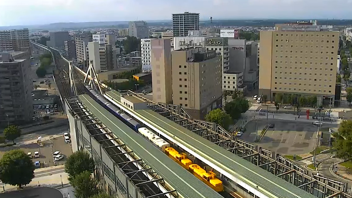
Enjoy patrons, enjoy.
DCC via an Arduino!
And now, back to the topic that started this entire blog: DCC! Back then, I was creating breadboard circuits to get a PC to talk DCC, and although it worked, it has now been made much easier thanks to the Arduino platform. All you need is a motor shield and an Arduino Mega! It seems that DCC on the Arduino started as a project named DCC++. Sometime around 2016, the 'great rewrite' occurred and DCC++EX was born. What follows is what's required to get this up and running in no time!
First off, you need a supported Arduino with a matching motor interface. My expectation is to use my PC to control the DCC trains, so I wont need any extra throttle hardware. For any electronics projects, make sure you have a solid power supply. Especially with DCC, which requires intricate signals running over the model railway rails, you should follow the power supply guidelines here, preventing any further issues.
To make life easy, I purchased a legit Arduino Motor Shield from Core Electronics and attempted to plug it into my Arduino Mega 1280... used in most of the Arduino posts on this blog.
Turns out, my Mega is so old that the pins don't even line up! Seems that the pin layout changed at some point in the last 11 years.
Luckily I had a spare Uno on-hand from previous Remote Control tinkering.
With the newer Uno, things fit together nicely...
Note that there's still a mod required on the motor shield to make sure that you isolate the USB power from the track power.
Following the instructions here, I cut/scratched the thin trace between the VIN pads on the board. With the pads still there, I can solder a jumper wire on later if I want to restore the use of the Arduino's voltage input.
Once you've got your hardware setup, plug it into your PC and make sure the Arduino interface is all up-and-running, including the installation of the Arduino drivers. You can then go and download the latest version of CommandStationEX. Extract the zip and open the folder, you'll find the PDE is associated with the Arduino IDE and can just be double-clicked. Finally, just make sure your Arduino is configured correctly (type/port) in the IDE and upload the sketch.
Note that the software above is just the code for the Arduino. The Arduino acts as a bridge, with its own command set, so you'll then need a controlling application to get trains moving. I downloaded and extracted WebThrottle-EX, but you don't even have to do that! On the computer connected to the Arduino, just run it from the cloud!
Firstly, hit Connect in the top-right. It'll ask you to choose a Serial Port, which USB2Serial should be listed. Mine was COM6 and it all connected straight away. From there, hit the Power Switch in the middle. Finally, you need to enter the vehicle ID in the top left and then hit the arrow to the right of it. Thanks to my record keeping, I knew the ID I'd set the Kirara to. With the number 12 in place, I toggled the headlights button and the headlights came on! The track was dirty and the vehicle wheels were too, so I flipped it over to clean and found...
Hah! I left a note to myself that I hadn't even seen this time-around.
I didn't need N Scale to work this time around, so I packed it all up in ready for a HO DERM install! Mission accomplished!
Mega Drive Circuit Board Repairs
A bunch of Sega Mega Drives came via the workbench recently, all looking for a 50/60hz mod and region unlocking. Two older Mega Drive 1s were in the batch and the first modded with zero concern. Unfortunately, the second wouldn't even boot... a quick opening of the case saw the reason:
This area of the circuit board is easily accessible from the cartridge slot and I can only assume that a screwdriver (or other sharp object) has been jammed in at some point, destroying a few traces. You'll also notice solder to the left, but that was me in a previous attempt to repair this. I tried again as I now have a USB Microscope and it really does work well for reviewing damage and making intricate repairs!
How not to repair it
I first-up thought I'd be able to use copper winding wire and simply solder to each pad where the IC contacts the circuit board.
From the shots above, you can see how quickly that process failed. The combination of using a soldering iron under a microscope, a large soldering tip and shakey hands meant that solder spread everywhere. Fortunately, solder wick cleaned all that up in no time.
Also how not to repair it
The next method was a little dodgy, but proved successful. From above, I knew i needed more room to solder, so the goal was to create this room by lifting and spreading the pins and running wires to the other end of the traces.
A multimeter found the other end of the traces and winding wire was attached.
Thanks to the tiny tweezers in the iFixit kit, I was able to bend, lift and then straighten the leftmost leg.
From there, the other legs were lifted easily.
Finally, they were all spread out both horizontally and vertically to make soldering as easy as possible. I then connected the right-most as it was only going as far as the local via.
With the wires hideously attached, I considered bending the legs back down... But a blind person could see my dodgy soldering job would make contact.
Instead? Glue gun to the rescue! Finally? Test. It worked!
Kangaroo Liner でGO!
2021's Timetable Revision is full of more surprises! First we had the innauguration of the new Fukuyama Rail Express from Ajikawaguchi to Morioka. Next up we have a new service known as the Kangaroo Liner, run by the Seino Group, from Nagoya to Fukuoka! The train is named after the companies' logo. Something quite similar to QANTAS, but backwards.
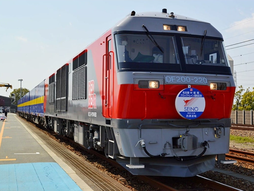
Above is the stock image that was sent out with all media online. I was very surprised to see a DF200 up-front... so-much-so that I thought there'd be a chance one would run the service! The media releases indicated that the train wouldn't be full of Kangaroo-only containers and that there'd be space available for other operators to hitch a ride.
| Location | Northbound | Southbound (read upwards) |
|---|---|---|
| Service | 5051 | |
| Nagoya Terminal | 2212 | 1823 |
| Inazawa | 2229-2237 | 1721-1804 |
| Gifu | 2258-0007 | 1559-1655 |
| Suita | 0201-0204 | 1245-1250 |
| Kobe | 0238 | 1210 |
| Himeji | 0309 | 1135 |
| Okayama | 0423-0432 | 0911-0957 |
| Hiroshima | 0646-0649 | 0554-0601 |
| Iwakuni | 0734 | |
| Shinanyo | 0850 | 0409 |
| Hatabu | 1028-1040 | 0219-0244 |
| Kita-kyushu | 1056-1106 | 0125-0202 |
| Fukuoka Terminal | 1247 | 0022 |
| Service | 5050 |
Westbound Service
The first train to leave was the westbound service from Nagoya to Fukuoka. At 2012 on March the 29th, the service departed and passed the Nagoya Station Camera not long after.
As you're watching the start of the video, you might be ready to tell me that it's "not the right train!"... but as the consist keeps rolling through the camera, you'll see that the Kangaroo-liveried containers are all piled on the rear. As mentioned above, there was always going to be spare room on the rake of flat wagons and the company was very happy to accommodate other operator's containers.
After travelling west, it then passed the Mukomachi Live Cam with quite a few more Kangaroo containers on-board!
From here, the Shin-Osaka cam picked it up, but it there was less-than-zero visibility. Unfortunately, there's no other cameras to the west to capture the action!
Eastbound Service
Due to this limited visibility out west, the first spot the train was seen was the Shin-Osaka Live Cam. The eastbound service seems to have at-least half a loading of Kanga-tainers.
After a stop-over at Suita, the train passed the Mukomachi Live Cam on time.
And then finally, back through the Nagoya Station Camera.
Looking forward to seeing these in real life... at some point... in the distant future.
Apple eMate 300 – Battery Refurb
Whilst fixing the hinges in my eMate 300, I noticed that there were also links to replacing the batteries. That link shows how to replace with proper cells, but it turns out that you could also use a battery holder.
I bought a full kit of bits to do the latter, but then realised that the installation required hacking out the existing cage for the battery. Not wanting to do this, I fell back to the soldering idea and wished I'd bought batteries with solder tabs instead of just standard AA-style cells.
Anatomy of a Battery Pack
The eMate 300 battery back has a socket with 5 pins/4 wires, a thermistor, 4 cells and a temperature switch at the far end. When replacing the cells, remember to keep everything but the actual cells themselves.
Peel the plastic off and then de-solder or cut all contacts. And keep the temperature switch!
Solder everything back together in the same order...
And then jam it back in the plastic case that it all came in...
If you're in luck...
You'll have a charging battery!
Testing it...
There doesn't seem to be an SSH client for the Newton (although people have tried), so I thought I'd go for Telnet. It seems easy to do over a serial cable, but I want to do it over Wifi! Thankfully there's the PT100v1.1 Client available over at United Network of Newton Archives.
Installing this got me a prompt... but a swift disconnection when trying to log in. But, the battery is still showing full charge after minimal use over two days! Win.
Fukuyama Rail Express でGO!
The Fukuyama Rail Express is an express rail-freight service run by Fukuyama Transporting Co, Ltd. Regarding rail-freight, they previously only operated a service from East-Fukuyama to Tokyo.
Here's a shot of that service from my travels in 2019, running past Shin-Osaka Station behind an EF66.
As of yesterday, a new service has been innaugurated from Ajikawaguchi (Osaka) to Morioka!
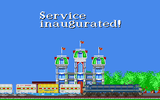
How bad is my photoshop? Note that the services only run on weekdays.
| Location | Northbound | Southbound (read upwards) |
|---|---|---|
| Service | 58 | |
| Ajikawaguchi | 2208 | 1600 |
| Suita | 2227-2231 | 1516-1528 |
| Gifu | 0023 | 1257 |
| Inazawa | 0038-0040 | 1229-1234 |
| Kasadera | 1206 | |
| Nishi-Hamamatsu | 0200 | 1025 |
| Shizuoka | 0259-0301 | 0902-0910 |
| Yoshiwara | 0826 | |
| Numazu | 0337 | 0747-0749 |
| Sagami | 0421 | 0656 |
| Yokohama | 0449 | 0629 |
| Shin-Tsurumi | 0505 (arrive) | 0615 (depart) |
| Loco swap and service change to 61 | Loco swap and service change to 59 | |
| Shin-Tsurumi | 0541 (depart) | 0541 (arrive) |
| Kajigaya | 0551 | 0532 |
| Niiza | 0625 | 0502 |
| Omiya | 0642 | 0449 |
| Utsunomiya | 0745 | 0351 |
| Kuroiso | 0838-0842 | 0259-0303 |
| Koriyama Terminal | 0931-0954 | 0007-0158 |
| Iwanuma | 2234 | |
| Sendai | 1147-1207 | 2141-2215 |
| Higashi-Sendai | 1217 | 2134 |
| Kogota | 2051 | |
| Morioka | 1433 | 1908 |
| Service | 60 |
Thanks to Japan's love of live-cameras, I was able to follow the service in both directions. Actually, as I start to write this post, both trains are still running both north and south. Anyway, let's rewind and check out what happened.
Light Engine to Ajikawaguchi
The northbound service started at Ajikawaguchi, just next to Universal Studios Japan in Osaka. To get the rake of beautifully-shiny containers out of the port, an engine was needed. EF210-156 was sourced from Suita and sent to Ajikawaguchi at around 1930 on the 23rd of March, 2021. Here it is passing the Shin-Osaka Live Cam.
It then passed the webcam near Fukushima Station.
Ajikawaguchi to Morioka
With the loco in place, the next step was to run the service! The consist ended up passing the Fukushima Camera around ~4 minutes behind schedule thanks to a late-running Haruka Airport Express.
Back to the Shin-Osaka Live Cam, it was nearly impossible to see it pass... but the audio is awesome in the night air!
Next up, it passed the Mukomachi Live Cam, amongst all the other freights and services.
A while later, it passed through Nagoya Station. Note the Shinkansen track vehicles working away also. That's a huge Tamper!
There's a great cam between Fuji and Shizuoka (which I've discussed before, recording times) and the train was seen passing through.
As that the train took the Niiza route through Tokyo, we couldn't see it on the Akabane or Shinjuku Cameras. Therefore the next and final camera was the Omiya Camera. The EH500 would've been swapped on at Shin-Tsurumi.
And that was it for the northbound. Congratulations Fukuyama Transport! Fortunately, we still had the southbound to stalk.
Morioka to Ajikawaguchi
The southbound left Morioka on the same night at 1908. It therefore passed the Omiya Camera before the northbound at around ~0450.
Whilst waiting for it at the Fuji cam, the northbound original Fukuyama Rail Express from East-Fukuyama passed by!
A little while later, the southbound was seen passing.
Next up was Nagoya Station.
And another guest came through an hour later...
And then again at Mukomachi Live Cam, right up the back, top-right, look really close!...
And since we're still waiting for the Fukuyama Rail Express to get to Mukomachi, here's Doctor Yellow passing Torikai to Shin-Osaka.
Whilst 'waiting at Mukomachi Live Cam', an EF65 passed towing a DD200!
And then, the main event at Mukomachi Live Cam.
Back through the Shin-Osaka Live Cam.
Through the Southern-Side Shin-Osaka Cam, one minute earlier if you believe system clocks... Also, this camera was down the previous evening when the inaugural service ran...
And then the final shot of the day! Past the Osaka Loop Line at Fukushima.
And that's a wrap!
Power Mac 6100/66 DOS Compatible – MIDI Out
After building the 'hydra cable' for this DOS Compatible machine, I quickly found out that the Joystick port could not be used for MIDI input/output. There were numerous hints online, and they all resulted to the fact that we'd need to solder a pin on the Vibra16 IC to get midi to the port. Here's the module removed from the DOS card. The CT2501 IC nearly takes up the entire board.
I was able to re-wire all of the below as I created my own hydra cable. I wouldn't suggest trying to modify an off-the-shelf cable as they're a sealed unit and have many pins incorrectly wired at the joystick-port-end.
Determining the correct pin
I'd asked online for help from someone who'd already worked out the solution, but hadn't received a quick answer. After rummaging through my junk boxes, I realised I didn't have a card with the correct CT2501 chipset, so I asked a few friends also. No one had the exact model required, so I considered purchasing one on eBay. They were averaging about one-hundred-dwollar shipped, so I decided to try and find high resolution photos online instead.
It turns out that dosdays has a fantastic library of information on the SB16. Included are high-enough-res photos of the rear of the board that allowed me to easily trace pin 12 (MIDI OUT) back to the CT2501 IC. Pin 15 (MIDI IN) wasn't so easy as it disappears under the 74-series IC in the bottom left of the top-side of the board. Fortunately, my main goal was to just get DOOM II throwing MIDI out to my SC-88.
After sitting in Paint.NET for a while, tracing traces, I came to the conclusion that MIDI OUT was Pin 30 of CT2501. In the pictures above, I've traced this in RED on the underside-shot of the board and YELLOW on the zoomed in CPU picture. MIDI IN is traced in BLUE on the underside-shot, but then disappears on the top half under the IC. Images from the web don't provide enough detail to allow me to continue the search! I was happy with just MIDI OUT, so I then started the quick hack-job to solder on a test wire...
In no time at all, DOOM II was outputting its soundtrack into my headphones.
Usually I'd pipe the audio-out from the SC-88 back into the soundcard of the computer that it was connected to, but that's not an option here with the Power Mac 6100 as it only has Microphone In! Oh wait, can I also wire-up Line-In for the DOS Card? I don't think that'd be as straight-forward as I'm sure there'd be a DAC and other components on the path.
External Connections
The port at the back only needed to be one wire, so I initially used an RCA socket.
I then realised I had no spare RCA plugs on-hand, so I switched the socket to a 3.5mm mono audio jack. This looked nicer anyway.
From here, a headphone cable was wired through with one of the channels running to pin 12 on the joystick port. This was then plugged into the SC-88 and DOOM II WAS PLAYED AT FULL VOLUME!
Power Mac 6100/66 DOS Compatible – MIDI
I couldn't resist this over-sized-pizza-box when I saw it on Facebook Marketplace. I never really check that area of the web, as the interaction mechanism is too loose... half the time you never even get a response from sellers and it doesn't feel real-time enough to trust if anything is actually available. Anyway, I threw a curve-ball offer and the seller responded (6 hours later)! The unit was picked up in short time, well actually... I had to wait for Victoria's 5-day lockdown to end. Yes, that was a while ago! It's been sitting in the junk room waiting for a video adapter cable thanks to it's HDI-45 video plug.
It's a beautiful unit. A much larger pizza-box than the LCs and it's even DOS Compatible!
Period-Correct Screen
By the time the video adapter cable came from America, I was ready to test the unit. I'd actually recently picked up a Trinitron monitor from the tip shop and it also needed testing! After a good sanitisation all round, everything was plugged together. To connect the Mac to the Monitor, I needed the HDI-45 to DB-15 adapter and then another DB-15 to DE-15 to get to VGA standards. With everything connected I got nothing... just a black screen... but I did get a startup bong! Myoldmac has a great reference on the video adapter settings and I had to use this as my adapter seems to have lost its packaging and the settings sticker on the actual unit. After a miriad of tests, the correct answer was to have 'separate sync' configured.
Ok, with a picture showing, I could now configure resolutions... only up to 832x624? What gives? Oh, This machine has 640kb of non-upgradeable VRAM limiting my choices. There's a good write-up here describing its system limitations. Turns out the AV Model has a separate card with 2MB allowing more resolutions on an external monitor. That wont work for me though... I have a DOS card in there!
MIDI By Roland
Before we get to DOS, let's just get my external SC-88 going. It's got a serial connection and I've always wanted to test it. Firstly, grab a game that'll support it and get that installed. Actually, there're too many options to choose from there. For fun, I'll load up DOOM II as, well, it has the easiest gameplay and a great soundtrack!
Grab a standard serial cable, make sure you choose a port that's free (i.e. not in-use by AppleTalk as you won't get a single message and it'll just not-work) and plug it all together. Make sure the SC-88 is set to "Mac" and that it has been power cycled since that switch was changed. Then power up the Macintosh. Don't expect anything to be hot-pluggable! But even then, nothing would be visible in the Quicktime Settings.
At this point in time, you can look over here for hints and then here for cable wiring and then here for the Roland manual and keep guessing why that Quicktime panel doesn't work... but don't bother.
No amount of cable-foolery got the basic Quicktime Installation to enable the General Midi checken-boxen. Instead, I software-foolery'd around until a version of OMS both extracted and installed. Note, if you've just installed MacOS, do not use the version of StuffIt from the Internet Utilities folder. It's archaic and will fail to extract things. Make sure you get a recent version installed first!
I need to discuss the middle shot above. It's telling you that, if AppleTalk is enabled, one of your Serial ports might be in use and the CPU will also be under pressure. Fortunately, our AppleTalk config is over Ethernet, so no Serial ports are in use! Is this software version for Macs with zero Ethernet capabilities? Eek... Anyway... auto-detect away!
Haha.. it found 16 Roland SC-88s... If I was a rich man? Must download some Beatles. After this, many duplicates were cleaned up until there was only one. From there, I scrolled down to check the other port...
The Yamaha MU80 didn't fair as well... it itself threw an ILLEGAL COMMAND error and the software decided it was a shitty Modem.
So.. just force it in the settings...
And then try again...
Music! Doom II sounded amazing.
DOS Compatible
PC Setup was already installed on the hideously-themed OS. I tried to boot it up, but the screen just went black! Turns out that unlike the previous Power Mac 7220, this one needed an external cable to route the video through. Googlin' around, there were a few options/schematics, but unfortunately this specific Power Mac had the HDI-45 Video port and therefore needed a hydra cable containing a different pinout. Thanks to the internet though, someone has already done the build and the pinout was available (and more over here). Here it is again for safe-keeping:
| Connector on DOS card 26-pin Male on cable | Video out on 6100 15-pin Male on cable | Video to monitor 15-pin Female on cable | Joystick connector 15-pin Female on cable |
|---|---|---|---|
| 1 | 2 (Button 1) | ||
| 2 | 3 (J1 - X) | ||
| 3 | 6 (J1 - Y) | ||
| 4 | 9 (Blue) | 9 (Blue) | |
| 5 | 5 (Green) | 5 (Green) | |
| 6 | 3 (CSYNC) | ||
| 7 | 14 (HSYNCGND) | ||
| 8 | 15 (HSYNC) | ||
| 9 | 4 (SENSE0) | 4 (SENSE0) | |
| 10 | 1,8,9,15 (+5V DC) | ||
| 11 | 11 (J2 - X) | ||
| 12 | 13 (J2 - Y) | ||
| 13 | 7 (Button 2) | ||
| 14 | 1,6,11,13 (grounds) | 1,6,11,13,14 (grounds) | 4,5,12 (grounds) |
| 15 | 1,6,11,13,14 (grounds) | 4,5,12 (grounds) | |
| 16 | 15 (HSYNC) | ||
| 17 | 12 (VSYNC) | ||
| 18 | 7 (SENSE1) | 7 (SENSE1) | |
| 19 | 10 (Button 4) | ||
| 20 | 1,6,11,13 (grounds) | 1,6,11,13,14 (grounds) | 4,5,12 (grounds) |
| 21 | 14 (Button 3) | ||
| 22 | 2 (Red) | 2 (Red) | |
| 23 | 1,6,11,13 (grounds) | 1,6,11,13,14 (grounds) | 4,5,12 (grounds) |
| 24 | 12 (VSYNC) | ||
| 25 | 3 (CSYNC) | ||
| 26 | 10 (SENSE2) | 10 (SENSE2) |
Each of the three plugs coming off the main plug need 13 wires each! I don't think I've ever had a standard 'round' cable in my arsenal that had more than 8 wires. Maybe I should trash a printer cable? Maybe I'll just heat-strink single-strands? If I cut the heat-strink up enough, it can 'telescope' down when I'm soldering and then I can slide the pieces up, bit-by-bit? Looking a bit like bamboo? It won't be too flexible though!
I started chopping up wires to use for the individual pins... until it occurred to me that pins were shared across all three secondary plugs. How does one share a wire succesfully? I'd actually need to construct 1-to-2/3 wires that split out into the differing plugs. At the final plug end, they can bridge all the pins they need to, but they need to get there first, without causing wire bridges 'outside' the initial plug housing.
So, with this in mind, I twisted two or three wires together where the ground feed needed to be distributed. I even used resistor legs to shift the major solder blob away from the plug solder pins.
Somewhere around the middle photo above I went slightly insane... and slept. Soldering and routing that many wires was a nightmare!
IT WAS EVEN WORSE ONCE A SINGLE END PLUG WAS ON!
But finally, a hydra-sorta-styled cable was assembled. All wiring was double-checked and then it was plugged together:
No way. It worked. I re-loaded the DOS image hard disk file from the original installation of Mac OS and found a copy of Win95B with an app that seemed to be a collection of "The Age" articles. Who-the-fxxx would want to have a source of that trash?
Unfortunately, it seems that all the data was on CD! So I shut it down.
Shiiiit.. haven't seen that in a LOOOOOONG while. I then tried to shut down the actual Macintosh... after Apple-Return switching back to MacOS...
What dat? Does this thing have an actual physical clicky power switch? i.e. non-atx-style soft power off? I pushed it and it did indeed click! I never noticed when turning it on!
MIDI via the DOS Joystick Port?
I was really hoping to hook up my Roland SC-88 to the joystick port, but no go. A quick google of pinouts shows that MIDI TX/RX signals are on pins 12 and 15 and these are tied to +5V and GND, which means it's actually REALLY DANGEROUS to hook up any MIDI device to this joystick-only port. Actually, I blab a lot on here, so let's just re-make that point...
Power Mac 6100/66 DOS Compatible Card Warning
Looking at the cable pinout table further above, it shows that we also don't have any spare pins on the 26-pin plug from the DOS card to squeeze MIDI through, so no wonder they prioritised video over the game port. Interestingly though, couldn't they have possibly spared two of those ground wires to pass MIDI data through?
It then occurred to me that we might be able to route the MIDI data through the Macintosh' Serial Port. To do this, I first connected my SC-88 (which has a very convenient Macintosh Serial Port on it!) to the Printer port and configured PC Setup to route COM1 to this.
From here, I downloaded and installed softmpu. This driver loads into RAM and intercepts all calls to the IO of the MPU on the Sound Card. The DOS Card fully supports the MPU, it's just that the output pins are literally un-wired! So, with the virtual tap, we can send the MIDI data out to COM1 instead, which is then virtually connected to the Macintosh Printer Port which is then hard-wired to the SC-88!
But it didn't work... softmpu just froze up the DOS side whenever executed.
Can we wire up the MIDI Port?
I then did a bit of Googlin' about those missing traces from the CT2501 Vibra 16 chipset. It seems that many have discussed it before, but each time it's ended in silence. Macintosh Garden's Comment Thread even tells me that it would've never worked and half of me wished I'd read that at the start as I probably would've not even bothered to wire up the port!
In 2019, BaldGoldEagle brought up the exact topic again on Vogons and got a good amount of detail, even after a direct bit of abuse from someone who didn't quite listen at the start (yeah, I'm talkin'bout you derSammler). The basic answer was to find a PC soundcard that has the same chipset (CT2260, CT2810, PB3110, CT3110, CT3930) and trace the pins to the port to work out what we'd need to build. The thread ended with a user offering to do so, but then the usual silence... I've just replied to see if anything came about!
A little more googlin' brought up a beautiful post dishing out on all of the DOS cards as they were built. Initially, the Houdini cards were mentioned as supporting MIDI! That was quickly corrected in the replies and the same result was reached: crickets.
I'll post again about MIDI once I've worked on it all a little more. (This now works! More information here!)
Random Photos
Search
Tags
Links - Click for details
- Abandoned Rails (Japan)
- AIRLINE (Shinkansen Photography)
- Akihabara Station
- annexpressのブログ
- Australian Model Railway Magazine
- DCC普及協会ホームページ (Japanese DCC)
- Dead Section (Japanese Track Diagrams)
- Delicious Things (Japanese N Scale DCC)
- Densha Wotorou
- Digital Direct for Windows (DCC Server)
- Don's Dream World – AMAZING N Scale Japanese Layout
- Hatena::Diary
- Japanese N-Scale Modeling Forum
- JR Chiisai
- Kaz-T's blog レインボーライン (Rainbow Line)
- LED Resitance Calculator
- Masioka
- Poppondetta Blog
- RailFan Magazine, Japan
- Railmind
- Railway Travelers' Room
- Serenity Valley
- Shashinka Ichiban
- Shuzuku
- Sumida Crossing
- The next station is…
- Tomix N Gauge Track and Japanese N Gauge Trains
- TT Forums (Transport Tycoon Deluxe)
- 名鉄尾西線の貨物列車 (Nagoya: Meitetsu Freight)
- 日本型Nゲージ DCC改造例のご紹介 (Okiraku DCC)
- 泰 茅 轍 道 (Taichi Railway)
- 箱庭登山鉄道製作記 (Hakone-Tozan Layout Blog)
Archive
- July 2026
- May 2026
- April 2026
- March 2026
- February 2026
- January 2026
- November 2025
- October 2025
- September 2025
- August 2025
- July 2025
- June 2025
- February 2025
- January 2025
- November 2024
- September 2024
- August 2024
- July 2024
- June 2024
- May 2024
- April 2024
- March 2024
- February 2024
- December 2023
- October 2023
- September 2023
- August 2023
- July 2023
- June 2023
- May 2023
- April 2023
- March 2023
- December 2022
- November 2022
- October 2022
- April 2022
- March 2022
- February 2022
- January 2022
- December 2021
- November 2021
- September 2021
- August 2021
- July 2021
- May 2021
- March 2021
- February 2021
- January 2021
- October 2020
- September 2020
- August 2020
- July 2020
- June 2020
- May 2020
- April 2020
- March 2020
- January 2020
- December 2019
- November 2019
- October 2019
- September 2019
- August 2019
- July 2019
- June 2019
- April 2019
- March 2019
- February 2019
- January 2019
- December 2018
- November 2018
- October 2018
- September 2018
- August 2018
- July 2018
- June 2018
- May 2018
- April 2018
- March 2018
- January 2018
- December 2017
- November 2017
- October 2017
- September 2017
- August 2017
- July 2017
- June 2017
- May 2017
- March 2017
- February 2017
- January 2017
- December 2016
- November 2016
- October 2016
- September 2016
- August 2016
- July 2016
- June 2016
- May 2016
- February 2016
- November 2015
- October 2015
- September 2015
- August 2015
- July 2015
- June 2015
- May 2015
- April 2015
- March 2015
- February 2015
- January 2015
- December 2014
- November 2014
- August 2014
- July 2014
- May 2014
- April 2014
- March 2014
- December 2013
- November 2013
- October 2013
- June 2013
- August 2012
- April 2012
- March 2012
- February 2012
- November 2011
- October 2011
- September 2011
- July 2011
- June 2011
- May 2011
- April 2011
- March 2011
- February 2011
- January 2011
- December 2010
- November 2010
- October 2010
- September 2010
- August 2010
- June 2010
- May 2010
- April 2010
- March 2010
- February 2010
- January 2010
- December 2009
- November 2009
- October 2009
- August 2009
- January 2009
- December 2008
- November 2008
- October 2008
- September 2008
- July 2008