


 Melbourne BG SCS Train Timetable


Donnybrook, Victoria – Candy XPT
I'd previously hinted at NSW Transport's goal of painting one XPT set into the original as-delivered colour scheme, but it happened to happen right as both the standard gauge and broad gauge lines into melbourne both had weeks of track closures. It actually turns out that the standard gauge closures finished earlier than the broad gauge timetable and therefore the XPT managed to cycle through the schedule and come to melbourne! Actually, the first time it did was mid-week where I wasn't able to see it. Instead, I saw it on a weekend when it made it down overnight on a saturday. This meant it headed north on the following Sunday morning:
And you know what? After the hideous days of signal failures in Donnybrook, the XPT flogged it through. Absolutely no issues of slow speed!
Thanks to the BG being shut down, shots could be taken from the middle of the tracks. Interestingly, that light-rail truck was sitting there as the BG rail workers seemingly had the weekend off!
What happens in Dubbo?
So, they painted a full XPT set in the candy livery... but when the XPT is scheduled on the West Dubbo service, it doesn't need the sleeper carriage. This service runs with a smaller consist and the sleeper carriage gets attached to another XPT set. The initial candy set is using XP2006 at one end and XP2009 at the other... but the XAM (the sleeper carriage) was then shifted over to the XP2012/XP2019 set. This then meant that we had a new consist to track!
And so I did... it ran the overnight to Melbourne and came through Donnybrook this morning...
Lot'sa wildlife at that time of the morning... and no fellow gunzels? I was mildly disappointed!
And yeah...
It's pretty obvious! After telling some passengers that there were no BG trains and that they needed to go to the bus stop, I went home!
Donnybrook Signal Faults, Victoria – April, 2026
A usual Saturday pub lunch turned into a day full of excitement early-on as the Northbound Shepparton service I was riding on got to pass a spark at Essendon Station. This never happens... as Melbourne has removed nearly all passing loops at stations that may have existed in the past. Yes, we have some lines that have three tracks to allow a peak express in specific directions... but ask anyone on the Frankston line lately if there has even been an express scheduled! Anyway, no images of this.. just a jolt as we switched to the wrong-road to pass through the station... it was nice to skip the stopper and get a run through!
I hadn't originally planned to head to Donnybrook again so soon, but I made an executive decision after seeing that the XPT was over 2 hours late. I could easily get a photo in nice morning daylight. Turns out the southbound V/Line Albury services were also 1+ hours late due to 'vandalism'. I arrived at Donnybrook Station on-time, as the broad-gauge services were still running to schedule. It turns out the vandalism was only affecting standard-gauge line.
Before-long the northbound Apex Gravel Train came through with a Qube-liveried G class. This service runs on the broad-gauge tracks and had no issue doing track-speed through the station.
Always a nice surprise... but then again, seems to be a consistent runner. Also it seems that there'll be changes to this service in the future and therefore different locomotives and wagons! As the consist headed north... I saw something weird going on with the standard gauge signals at the start of Donnybrook Loop.
The switching of the aspect didn't look healthy at all... and had probably contributed to the lateness of the XPT. I'd wondered if the control tower was trying to force the signal to a certain aspect, but the next service was southbound! Or was the signal control circuitry going into a fail-safe mode? Showing a green really didn't feel safe though... as the Southbound 8610 V/Line service was due through 'soon'.
8610 appeared, and held at the exit signals for the loop... which I assume were also doing bad things. I should also point out that the service came down the loop (and not the main track), which was simply weird!
After a lot of stalling and crawling along, it finally exited the loop and crawled through the level crossing. At this point, I think it was well-over 90 minutes late. I feel sorry for anyone who needed to be in the city! The northbound XPT service, by this point, was over 2 hours late and had been sitting in Somerton Loop. 8610 crawled south at 20km/h past Somerton allowing the XPT to crawl at 20km/h north through to Donnybrook!
It actually snuck up on me... usually the level crossing gates will kick off way before you see the train. I was busy watching an episode of Yellowstone and just happened to look up at the right time.
I imagine the driver was in constant comms with the control tower trying to get the gates lowered at the right time? Either way, they finally lowered and the XPT crawled through.
The gates lifted and the XPT screeched to a halt right next to the pub.
The signals were flicking whilst the XPT was trying to enter the loop... which it shouldn't have had to as there was no train on the main.
Whilst it had a split-second green, it proceeded through the points... right as a southbound Sprinter came through.
Watching the data, the XPT then hit 100km/h for the first time on the trip once it exited Donnybrook Loop. Another train-load of unhappy customers! Speaking of such things, 8612 came south, around 90 minutes late.
The gravel had loaded in Kilmore East and made it's way back into town.
If you check the middle shot, you'll see the signals were still flipping red to green and that the points were still stuck on the diverge.
I was still up the wrong end of the platform when I saw a northbound freight on the SG. Surprisingly, they let 7MS1 depart Dynon, knowing it'd be a struggle to get out of Melbourne city limits.
It absolutely crawled through the crossing... coming to a halt. Unlike the XPT which could clear the crossing, this freight was longer and held the gates down, causing quite a traffic build-up!
The end wagon happened to have no containers... so I'm sure some drivers at the back were wondering what the hold-up was!
That was it for the trains and I skipped the next city-bound V/Lo as it was full and standing wasn't preferable. You can see that the weather was rolling in above and this treated me to a great view out the window!
And another shot from the phone...
The tint on the window made the double-rainbow effect really obvious!
Macintosh System 7 on x86?
Rabbit holes... My regular morning peruse of HackerNews saw me read this article on Mac OS X being ported to the original WII. Amazing, I thought to myself... I wonder if I can skip the emulator on my X68000 and port Macintosh System 7 to it directly?
I went off to read the actual blog over here. Brilliant write-up and beautifully presented. Coding on Trains and Planes... and even in Hawaii? Love it!
The comments on HN had interesting hints to the source of System 7 being available? I googled and found this github project. WTAF? Hah. Someone is having a good set of 'sessions' with an AI agent, making it disassemble, understand and re-write System 7 so that it'll work on x86? There are even released ISOs? Nuts! Does it work?
& 'C:\Program Files\qemu\qemu-system-i386' -cdrom system71-en.iso -vga std -m 256M
And wow.. it... works?
A bit clunky. Mouse works and Simpletext opened! What about on real hardware?
Burn a disc and then see if my Dell Dual-PII will boot it...
5 seconds later and we were in! Mouse moved for a bit then it all locked up. I'M IMPRESSED! Keep this alive!
Sharp X68000 Pro – RAM + HDD + Power
I couldn't believe it. seeing a full set X68000 Pro on the shelf at the Ota Road Super Potato in Den Den Town, Osaka. Of course, the staff instantly told me it was for display only and didn't work! The story was that they'd bought it a few years back and it worked then, but since had stopped working. The monitor was fine, but the main CPU was not turning on. It was therefore 'KAZARI'... decoration.
I was happy with decoration, for the price. Shipping was to be another concern. Fortunately, Super Potato is partnered with a logistics firm upstairs and Mori-San and X-San helped describe the process to me. I'd buy the unit on the day and wait until after Golden Week for them to contact couriers and provide a quote. I'd then pay via Paypal and they'd ship the unit to me! Easy!
To be honest, after turning on and playing a few rounds of Bubble Bobble, the poor thing has been sitting as KAZARI in the corner of my study/office for quite a while. I recently made a 3D-printed bezel cover for the monitor, which doesn't look too bad! Regardless of all the work to that point, I'd recently come to the realisation that I either need to move it on... or actually learn how to use it!
The machine works great... floppy games load fine... but that's not fun-n-technical enough... I want to use HDDs, CDs?, MOs? and work out what that CPU Clock Switch does... and how to use the memory cards. Also, can I rig up an ethernet to serial adapter to get data transferring over to it a little more easier? Maybe even use a BBS?
Random Access Intricacies
Understanding RAM in an X68000 is mildly difficult. It seems that, nearly akin to an Amiga, there's a clear distinction between system/onboard RAM and extra supplementary RAM. I suppose that goes for PCs too with conventional vs. extended RAM, etc... Anyway, to use any I/O slot memory expansion boards, the base system needs to have 2mb of internal memory. From the factory, X68000 ACE, PRO and PROII systems only have 1mb and so a CZ-6BE1A module is required. Fortunately, this machine already came with the module installed!
With 2mb onboard, you can then tinker with I/O slot memory cards. I was googlin' at some point and saw a good deal on an XSIMM10 card, so I bought it! Little did I think to check the blank plates on my machine to see if I already had one? Turns out I did! How hilarous.
Left-most above is an I.O Data PIO-6834-4 4mb memory expansion. There's a jumper block to set where this memory starts in the memory map. Since we've got 2mb onboard, this card must start straight after that and provide another 4mb, taking the machine to 6mb.
The other board above is a XSIMM10 memory board which will allow up to 10mb of memory to be added! These cards can be configured to place the two pairs of memory wherever needed. Interestingly, the configuration examples show a 4mb "system" area above the 10mb additional RAM? Does that mean these cards can be used together?
In the end I only used the XSIMM10 with the full 8mb populated to bring the machine to 10mb.
SASI/SCSI HDDs
There's a great tutorial here for setting up HDDs. It seems tho, that you're expected to use one of the devices specified and not just boring old spinning-rust. I tried three external SCSI drives that I had laying around, connected to the 50-pin SASI centronics port and couldn't get any of them to work. Anything from stalling INITs to "device not operational" to "cannot xxxx".
After trying the units above, I turned to the internet and sought help. This magical post indicates that not many SCSI drives are compatible and for those that are, they need to be able to have parity disabled. I don't even know what that is! That flat beige unit above has an ST11200N inside... and it seems that parity should be disabled by default. I popped it open and found...
A slew of jumpers enabling parity! I disabled it, but had no luck.
Further goog'lin brought up this excellent article at gamesx... and that last little paragraph is a killer.
SASI models will be somewhat limited in terms of what drives can be used. First and foremost you'll need a drive that doesn't require parity (if you don't want to build the parity faker circuit). Even then, you'll run into plenty of drives that just won't work even though they can have their parity disabled.
There's a table there with two 1GB drives listed... and they're both listed as no-worky. The table also lists the Quantum ProDrive LPS42S as 'working', and I have two in my HDD box'o'junk!, so I tried them all out. After a lot of tinkering, I couldn't get any of those to work either. So, I tried my SCSI2SD. It also showed no signs of life, until I jumpered the Termination Power pins!
The best thing is that I have a terminator with an LED in it, no idea where that came from, which shows me if the bus has power on it. The LED only illuminates when there is termination power on the bus and, up until this point, it'd been off the whole time. Finally, with the SCSI2SD TERMPWR jumpered, the light lit up!
Of course, if I'd read the bloody manual for the SCSI2SD earlier, it would've been obvious from day one:
    Sharp X68000
        SASI models supported. See gamesx.com for information on building a custom cable.
        needs J3 TERMPWR jumper
        Set to SCSI ID 3. ID0 will not work.
Ok, we're learning. From here, with the drive initially as ID 0, the machine would freeze if the drive was already powered on before the machine was started. So, instead, I started it after the boot process.. allowing me to format it! I then set the drive back to ID3 and, after following these instructions, I installed the SxSI BIOS in SRAM and the machine booted from the drive!
So, with this now understood, could I get an older drive to work? The Conner 3040 42mb Drive supposedly has Termination Power and Parity options. With this drive connected... the terminator light... didn't light up?
So, can we inject terminator power? In the SCSI2SD schematic, they're just feeding +5v into pin 26 on the SCSI cable, but then also providing 3v3 to the termination resistors... does my "active" terminator with the LED also do the 3v3 conversion and just needs the 5v power rail?
Actually, we can test this using a better method first. Let's leave this unit on the SCSI chain, but set it up to some higher ID and then slap the Conner at ID3 before it. Even with all this trickery, I couldn't get a spinning-rust drive to cleanly format.
So, instead, let's switch back to the SCSI2SD and follow the instructions to use the HDD image from here. After writing it to the SD card, the unit booted up perfectly with all 3 partitions showing!
What about running floppy games from the HDD?
Yeah, this was confusing.. until I google'd and came across this link. Wow. You can just run the autoexec.bat from the folder? Works for some games... not all.
Bubble Bobble ran .. but sounded totally weird! I then delved into the world of X68000 Music Drivers, realising that the bootdisk had OPM3DRV loaded first. When I then ran autoexec in the bublbobl folder, it loaded GMD68K.r over the top and ... haha ... What a symphony! It seems that loading two drivers in sequence causes all sorts of issues. I then tinkered around by installing the Roland MIDI Card, trying to see if it'd work on MIDI. Turns out there's absolutely no setting to enable MIDI... and then it actually stopped playing music altogether?
Overclocked? Me?
Turns out the previous owner already had an overclock switch/mod installed which toggled between a 40mhz and 60mhz crystal and that I'd accidentally flicked it! It's hiding at the right edge of the top expansion slot cover.
Internally, there's a piece of veroboard with some 74-series logic to allow a solid-state selection of which crystal to use. Above, if you check out the first photo in the RAM area, you'll see where the twisted-pair blue wires run to where the original 40mhz crystal would have been on the mainboard. The other wires run to one of the front-panel LEDs.
This switches the internal system speed between 10mhz and 16mhz (thanks to clock dividers) and Bubble Bobble hates this! I must admit that I'd seen the internal wiring and obvious mods, back when I first received the machine, but never cared to think what repercussions could be caused by flicking it! Turns out that games for the X68000 are very fixed on expecting a 10mhz clock and that Bubble Bobble's sound driver HATES 16mhz.
So, what to do? Make AI write a CPU speed detection app. I used the dev environment from Chibi Akuma's Site and saved a screenshot of the site for posterity:
It's beautiful. Anyway, code was 'written':
And it even worked! Thanks Gemini! It's very friendly with you when coding:
The source and binaries are downloadable here.
Power Supply
I started to have a weird boot-loop issue where the machine would click on, but then quickly click off again... and loop at about a 2-second cycle. It sounded bad, but would "fix itself" after a 30-minute cool-down. The worst in me suspected the power supply was going... so I braced myself for impact.
Christ. Those two 3300uf caps are juicy...
Crap photo.. but that 1000uf cap at the back is also ready to launch!
Quick work was made of extracting, cleaning and replacing the culprits...
Anyone who has done this before can smell the above picture. A ionizer in the other room actually turned on thanks to the tuna-flavoured solder-fumes that were wafting through the apartment.
Take it easy when clearing the silicone as there are components buried in it. I had to repair a jumper wire which I'd accidently dismembered. Also watch out for the height of the 2200uf cap which needs to fit under the external power port.
Meanwhile, check out the filter cap on the main-board which was hiding under the power supply? Factory bodge? Seems to be the same silicon!
Programming / Linux?
Maybe it's time for a DOS port of OpenTTD? I could use this gcc compiler? Or this huge repo of sample C++ source? It also seems that NetBSD can be installed, but an MPU is required.
Hah, you can even follow these instructions to run a Macintosh?
A-Train (III) – Taiwanese Big Box Edition
This showed up on eBay and I fought a hard negotiation to get my hands on it. It was actually a few years ago... and I've only just thought to open the box and check if the disks work! Actually, the same seller still has another copy of it, and a copy of the Construction Set on eBay... still for crazy prices.
The box is mildly grotty... and it gets worse on the inside. The floppies are white, with quite colourful labels. Very pretty, but they also contained a concerning amount of grime as I spun the disk in the insert.
Initial attempts to read the disks failed miserably. Rawwrite just threw random errors and attempts to clean the disks didn't work. I then googl'd for methods and everywhere just seemed to indicate isopropyl alcohol. Most also came with the warning to NOT insert the disk whilst it was still wet.
... I, of course, didn't bother to wait for the alcohol to dry... instead believing it might also help keep the drive heads clean. Things started to progress and read percentages were starting to get higher and higher, but Rawwrite wasn't fun as there was no mechanism to "retry on fail". That's where IMD came in...
I set the retry count to 200 and let it chugggg.... and chug it did! On the first attempt, it got to the end of the first disk, but, as you can see above, it still failed on 2 of 78 sectors. I thought this was the end, and so I put the disks back in the box and attempted to forget about it.
The next day, I had decided to try again and attempted to image the first disk again with IMD, using the same settings. Would you believe it just worked? No extra cleaning... nothing. It chugged a little and performed a few sector retries, but it got there!
I then proceeded to install the game after writing the first disk to a spare floppy. I'd stupidly only written one disk and started the install... realising that I'd have to use the 2nd and 3rd originals ... but it worked! They'd had a few issues when imaging, but somehow the continual reading must have cleaned them up.
Booting it up...
Everything in the installer felt very stock-standard and I'd therefore assumed the game would be stock A-Train (III) with a spattering of Mandarin (maybe Taiwanese Hokkien?)... but boy was I wrong. They've added two introduction movies and even copy protection!
Here's a shot of the copy protection screen...
And here's where they stored the password on each of the 104 pages!
Turns out the password is a tiny code down next to the page number.
| Page | Password | Page | Password | Page | Password |
|---|---|---|---|---|---|
| 1 | 25875522 | 36 | 14243140 | 71 | 62352272 |
| 2 | 44566583 | 37 | 85133224 | 72 | 17234771 |
| 3 | 40512782 | 38 | 22178342 | 73 | 27873449 |
| 4 | 64891227 | 39 | 73823428 | 74 | 74255934 |
| 5 | 78675662 | 40 | 99999887 | 75 | 39287474 |
| 6 | 77867901 | 41 | 99320300 | 76 | 36234550 |
| 7 | 68214782 | 42 | 88775227 | 77 | 50249444 |
| 8 | 49853011 | 43 | 69525288 | 78 | 37278465 |
| 9 | 02035103 | 44 | 29405864 | 79 | 24735836 |
| 10 | 13789344 | 45 | 70850613 | 80 | 33456220 |
| 11 | 13899239 | 46 | 00239333 | 81 | 73455398 |
| 12 | 84390523 | 47 | 53978222 | 82 | 27236748 |
| 13 | 50040624 | 48 | 78923234 | 83 | 22329223 |
| 14 | 18952636 | 49 | 28090230 | 84 | 12282518 |
| 15 | 69054305 | 50 | 28475225 | 85 | 88934394 |
| 16 | 21228041 | 51 | 37893410 | 86 | 28035258 |
| 17 | 00705623 | 52 | 94037394 | 87 | 12441523 |
| 18 | 25254987 | 53 | 34930563 | 88 | 12214957 |
| 19 | 01009344 | 54 | 39344380 | 89 | 73433924 |
| 20 | 21483224 | 55 | 76823322 | 90 | 32312330 |
| 21 | 93887144 | 56 | 51834345 | 91 | 11243238 |
| 22 | 20239842 | 57 | 96387544 | 92 | 82532741 |
| 23 | 33432022 | 58 | 59335520 | 93 | 42141135 |
| 24 | 72445256 | 59 | 10193113 | 94 | 33259738 |
| 25 | 34423425 | 60 | 34589996 | 95 | 85645716 |
| 26 | 24343902 | 61 | 73534569 | 96 | 51112158 |
| 27 | 55325732 | 62 | 91456792 | 97 | 82223373 |
| 28 | 89573497 | 63 | 11155014 | 98 | 21477212 |
| 29 | 45126456 | 64 | 82523976 | 99 | 13382228 |
| 30 | 67458981 | 65 | 56986069 | 100 | 38840892 |
| 31 | 22379296 | 66 | 96451236 | 101 | 56879571 |
| 32 | 29478247 | 67 | 22423329 | 102 | 46358761 |
| 33 | 35624354 | 68 | 75234252 | 103 | 56879156 |
| 34 | 28914467 | 69 | 39732523 | 104 | 21476212 |
| 35 | 68522276 | 70 | 88342579 |
I'll attempt to hack the code out of the EXE shortly. I did get bored and sent the first 10 numbers to Google Gemini... seeing if it could work out a pattern, but it had zero fkn chance. And finally, here are the disk images in IMD and IMG formats for anyone who wants to play at home. There's also the installed HD folder that you can drop straight into DOSBOX. Also, the EXEs have been unpacked, where possible, to allow better disassembly... when I could be bothered... to try and work out how the copy-protection works... I wonder if it looks up a byte in memory? Or in the EXE?
Yamaha P-95B – No Sound – Repairs
Have been looking for a midi-enabled nice-sized weighted-key keyboard for a while and saw a P-95 on FB Marketplace going for AU$500. I felt it was a bit steep for a pretty-old piece of kit, so I googled a little... initially just to confirm it had MIDI ports.
I then stumbled across this absolute cracker of an ad for a P-95 at a local music shop:
Turns out Music Swop Shop in Carlton is a treasure-trove of 2nd-hand music equipment... and they'd decided this unit wasn't worth repairs. Likely SMD repairs, they say?...
The unit was lugged home and open-brain-surgery ensued. The keyboard would react to note presses... I could see that record would flash until a you started playing... so the keys were operational and the panel seemed ok. The main issue had to be voltage/audio amplification? It turns out that the X8828 Amplifier Board seems to fail a lot... to the point where there are multiple "send it to us and we'll fix it" services!
I popped the board out of my unit and ... it looked bad. That crap cleaned off, but I was getting a lot of shorts across a LOT of the shitty little blue electrolytic caps? This turns out to be quite a common problem! That thread is hilarious, and I must add my repair to it. So many people with so many dried up dead caps.
With some of the caps, a slight touch from the top-side would actually push the leg through and detach the pad on the bottom-side! Hacks were put in place, thanks to enough space being available inside the piano.
All caps were replaced, for good measure. When reinstalling everything you need to BE VERY CAREFUL with the ribbon cables. I don't know if it was me or the previous repair-man, but the silver wires were starting to de-laminate at the ends where the ribbons plugged into the sockets. If you then put them in at an angle you could risk folding the silver back up on itself. Just be very gentle and precise when putting it all back together... otherwise you'll do what I did and dismantle it 10 times as the unit failed to respond every time I re-assembled it!
Anyway... I eventually got the ribbons in cleanly and then it all just worked perfectly!
Even MIDI-OUT!
So yeah, if you have a vintage Yamaha like this, then replace all the caps.... as the caps that aren't dead yet won't have much life in them either.
Donnybrook (Hotel), Victoria
Since around November last year, I've been choosing to enjoy Saturday lunch times at Donnybrook Hotel, adjacent to Donnybrook Station in Donnybrook Victoria. It the first diesel-only V/Line station on the main-south (main-north?) line out of Melbourne. The station is only served by V/Line broad gauge, having the standard gauge pass by without any platform connectivity.
From the platforms, you have a great view in both directions... as well as the smoking garden at the pub.
Both directions are very easy to frame, north (southbound) from the platform and south (northbound) from inside the fence at the level crossing. But yeah, the pub?!....
Donnybrook Hotel
Great food, great staff, great atmosphere and in a perfect location! You can sit inside on the bench-window and just stare into oblivion, waiting for a train to appear.
That last shot is from the bench inside which has always had a stool free! And so yeah, let's start with the standard services which will (usually) pass through on a 2025/2026 Saturday morning...
Northbound XPT - ST24
The 'slug', as it's affectionately known, is used on the Melbourne-Sydney XPT Service. If you're REALLY early, you'll see it pass south through Donnybrook around 6am. The northbound service is then due through at 9:09am.
Note that one or two of these consists will soon be painted back to the original "candy" livery! Can't wait (and I'll add photos here if they come to Melbourne.)!
V/Line Albury Up - 8610/8612/8620
On Saturday morning's there's an extra down service from Albury to the big smoke! Photos of these are like shooting fish in a barrel, off the north end of the southbound platform. Actually, I should try the northbound platform next... for a slightly different angle.
8612 can also possible pass the northbound Shepparton on the BG... I missed it this time:
Would've been nicer if the BG had departed... but such is timing!
A great angle from pub-side also.
Northbound Kilmore Quarry Train - 9341
This is usually a single CFCLA G-Class and a rake of yellow/orange hoppers. It grabs a whole lot of rock from Kilmore East Quarry and delivers to either Westall or Brooklyn where they turn it into cement.
7MS1 - Aurizon Melbourne-Sydney Container
This train is due through Donnybrook at 11:15, but it's usually early. For 2 weekends in a row, the same ACD6057 loco was on point...
The next 2 weekends, it was ACD6073 instead.
Finally, something different... but not. CM3316 in the lead, two weekends in a row.
7MS2 - Pacific National Melbourne-Sydney Container
This service is due through at 13:30 and would only be seen if I chose to stay past the 1:04pm Southern Cross Service.
5BM9 - SCT Brisbane-Melbourne Freight
This service is due through Donnybrook at 07:40am and I've never seen it less than 4 hours late!. It's meant to stop in the loop north of the station for 15 minutes to pass a V/Line service, but it doesn't seem that the V/Los have ever had to worry. Either way, I'm not complaining as getting to Donnybrook before 8am would be hideous.
And then from the level crossing, looking north...
7MC2 - Pacific National Melbourne-Griffith Container
This one is much later in the arvo, passing Donnybrook around 15:30. Actually, it seems to have been scrapped from the most recent timetable revision... but is still running?
Southbound XPT - ST23
If you're hanging around late enough, the opposing 'slug' should come through around 1750.
Just enough light towards the end of summer.
Unscheduled Services
Both run by SSR, and well, one is scheduled and one is not. First, the ad-hoc movement of two bulldogs:
And second, an xCMx grain train, which I've only seen come through once!
After track closures, you may also find random southbound BM services...
And then randomly... when Broken Hill is having issues, you might get a continent-crossing Perth-Sydney Service!
7PS1 in this case. As this passed, the southbound 9342 Quarry Service passed. Was a little crazy standing in the level crossing!
A nice fluke occurred recently with a broad-gauge 9396 Tocumwal to Melbourne grain train!
Look at that... N-Class locomotives still running on the BG after V/Line has disposed of them.
V/Line Passenger Services
From the little ones, known as Sprinters, which are now becoming very rare! I think Seymour is now the last proper-V/Line service (Metro uses them down south) where Sprinters are still scheduled.
They get lashed up anywhere from 2 to 5 in a row. 2 is the minimum so as to confirm proper axle counting at level crossings.
And then you have the V/Locities. They come in "three" styles... old with narrow windscreens on broad-gauge...
New with wide windscreens on broad-gauge...
And finally, the same wide-screen on standard-gauge...
Kilmore-East Broad Gauge Quarry Service
And then there's sometimes a random BG gravel service... but I haven't caught it at Donnybrook yet... so here it is at Jacana...
That track don't look too safe!
Getting A Locally Debugged Logic App’s Callback URL
For those of you who want to locally automate testing of Logic Apps running in VSCode, this post is for you! Across the web, there are people asking for a dynamic way to get the Callback URLs for locally debugged logic apps. They run via func.exe and it has been previously thought that the only place to get the URL with the required 'auth' signature was the overview window of the workflow:
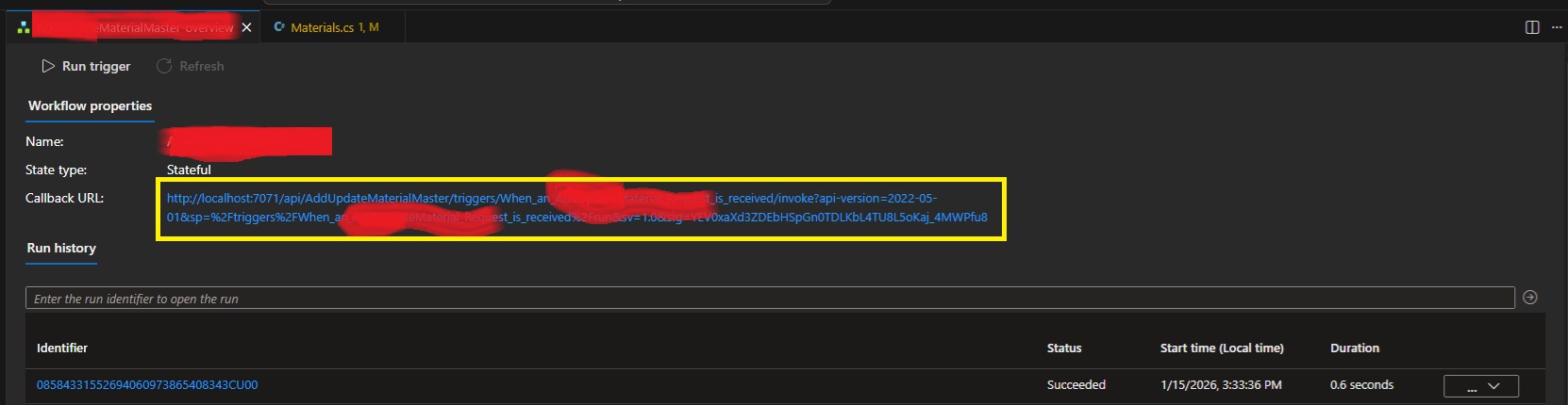
Fear not! I've used the development tools to rip apart VSCode and have worked out that our trusty local func.exe exposes all the webservices that Azure does! The full list of services available is over here. Specifically endpoints to list workflows, workflow triggers and then trigger Callback URLs with full signatures!
internal class LogicAppDetector
{
    private string base_url;
    public LogicAppDetector(string baseUrl = "http://localhost:7071/") {
        this.base_url = baseUrl;
    }

    public List<LogicAppWorkflow> GetListOfWorkflows()
    {
        var workflowListJson = WebClient.DownloadAsString(base_url +
            "runtime/webhooks/workflow/api/management/workflows");
        return JsonSerializer.Deserialize<List<LogicAppWorkflow>>(workflowListJson);
    }

    public List<LogicAppWorkflowTrigger> GetWorkflowTriggers(string workflowName) {
        var triggerListJson = WebClient.DownloadAsString(
            base_url + "runtime/webhooks/workflow/api/management/" +
            "workflows/" + workflowName + "/triggers");
        return JsonSerializer.Deserialize<LogicAppWorkflowTriggerContainer>(triggerListJson).value;
    }

    public string GetWorkflowCallbackUrl(string logicAppWorkflowName)
    {
        var wf = GetListOfWorkflows().FirstOrDefault(x => x.name == logicAppWorkflowName);
        if (wf == null) {
            throw new Exception(
                "Couldn't find workflow [" + logicAppWorkflowName + "] in the list?");
        }
        var trigs = GetWorkflowTriggers(logicAppWorkflowName);
        if (trigs == null) {
            throw new Exception(
                "Couldn't find triggers for workflow [" + logicAppWorkflowName + "]?");
        }
        if (trigs.Count() != 1) {
            throw new Exception(
                "Incorrect trigger count for workflow [" + logicAppWorkflowName + "]" +
                " ... count was " + trigs.Count() + "?");
        }
        var callbackUrlJson = WebClient.PostJsonData(
            base_url + "runtime/webhooks/workflow/api/management/workflows/" +
            logicAppWorkflowName + "/triggers/" + trigs[0].name +
            "/listCallbackUrl", null); //payload is actually NULL.
        var callbackData =
            JsonSerializer.Deserialize<LogicAppWorkflowTriggerCallbackUrl>(callbackUrlJson);
        return callbackData.value;
    }
}

internal class LogicAppWorkflow
{
    public string name { get; set; }
    public string definition_href { get; set; }
    public string href { get; set; }
    public string kind { get; set; }
    public object triggers { get; set; }
    public bool isDisabled { get; set; }
}

internal class LogicAppWorkflowTriggerContainer
{
    public List<LogicAppWorkflowTrigger> value { get; set; }
}

internal class LogicAppWorkflowTrigger
{
    public string id { get; set; }
    public string name { get; set; }
    public string type { get; set; }
}

internal class LogicAppWorkflowTriggerQueries
{
    [JsonProperty("api-version")]
    public string apiversion { get; set; }
    public string sp { get; set; }
    public string sv { get; set; }
    public string sig { get; set; }
}

internal class LogicAppWorkflowTriggerCallbackUrl
{
    public string value { get; set; }
    public string method { get; set; }
    public string basePath { get; set; }
    public LogicAppWorkflowTriggerQueries queries { get; set; }
}
You'll just need to plug in whatever you're using for Web Requests to GET and POST. Also make sure that the actual Logic App is running/debugging in VSCode!
Leave a comment if you have any issues.
ATX12VO – MSI MPG Trident AS
So this rabbit hole got very deep, very quickly! Bought a new machine... a smaller form-factor unit with great asthetics! Little did I think about any upgrade paths.
It came with an 8gb 4060 Ti which has been flawless for my needs, but I'm thinking I need 16gb... so... as that it's got enough room inside for a better video card? Why not?
I chose an RTX 5070 Ti based on price and RAM. As I was buying the card, the cashier told me I'd need 750+ watts of power and tried to sell me a new supply on-the-spot. Instead, I decided that I'd get home and check what was in the tin first, as brief googlin' indicated that some Tridents came with a Gold Power Supply.
But nope... my MSI Trident contained a 500w SFX. So, I went back to another PC store that afternoon and bought a Cooler Master V850 SFX Gold. A nice amount of power for my card!
Unfortunately, no amount of cable-jiggery-pokery would get the new ATX motherboard power cable to connect to the motherboard power socket? What gives? It turns out the Trident uses an ATX12VO power supply! A short-lived game-over ATX standard that Intel tried to push. They failed so-much-so that the standard has already been forgotten about. I take it I didn't realise how old this PC already was when I bought it. It was a refurb, so it probably lived its life in a gaming cafe.
Trying to find an exact ATX12VO SFX PSU with the correct wattage turned out to be futile. They just don't make them anymore! I started considering re-wiring the old plug from the old supply onto the new PSU, but there's a single pin that doesn't match: +12VSB. This wire is a constant 12v from the power supply to the motherboard for ancillary services. Things like charging USB devices when the machine is off (which could actually cause a lot of current draw?) and the power switch... which, thanks to ATX soft-power, needs a constant current trickle to determine if you've pressed it! I could possibly buck-convert the DC, like other people have tried... there's even a project for it here.
The googl' rabbit-hole went deeper and intially I found that Corsair has a custom cable, but I'd already purchased a Cooler Master! I then stumbled across Moddiy's site where they mention Cooler Master and ATX12VO on the same page! They'll create the custom cable for you with inline 12v boost for VSB!
In that last shot it looks like a snake processing a big meal, thanks to the heat sheath.
Cooler Master V850 SFX Pinout
The cable came with no mention of which end was for the PSU. Both ends have the same "ATX plug shape", so I didn't want to plug the damn thing in backwards. IF I had attempted to plug it in, I would've realised that only one side will go into the motherboard, but I was averse to doing it that way.
Instead, I started reversing both ends of both the power-supply-included cable and the new Moddiy cable to work out what was what. Turns out I really only needed to reverse the Cooler Master original cable on the plug, not the socket.
So, looking at the above cable, as it's shown, you get the following pinout:
| 10P M/B cable (not socket), looking at the plug with the notch facing up... | ||||
|---|---|---|---|---|
| 12v | 12v | -12v | +5vsb | POWER_OK |
| GND | GND | GND | 12v | 5v |
And that means the end of the cable with the 'top-central' pin missing is the Power-Supply side. The end with the 'loop' wire is the motherboard side. Everything routed through to the other end, as expected to match the ATX12VO standard.
Of course, the +5VSB didn't, as it goes through the inline DC converter which prevents a continuity test.
Mounting It In The Case
After taking the side panel off the machine, you'll find that the existing power supply has a mains lead running from the rear of the case to it's mounting bracket at the front.
First up you'll want to remove the 4 screws under the machine to release the mounting bracket.
Next, you want to gently push the power supply and bracket up, compressing the cluster of cables above to clear the bottom edge of the case.
Make sure to move any WiFi antennae out of the way! Once clear, the power supply can be lifted out via the base, disconnecting all cables (2 motherboard and 1 PCIE) at the same time.
From here, remove the base and attach it to the new power supply. Make sure that the notch is facing right when the power supply fan is facing you. This will allow the fan to line up correctly with the vent on the other side of the case.
Also make sure you switch the bloody thing on if it has an external switch like this one does! There'll be zero access to that once it's installed. Finally, connect the power cable and slide the new supply back into the case.
Line up all the WiFi antennae so you don't pinch them on installation! Route the required power cables to the expected sockets. I actually considered running the SATA power to the drives to take the pressure off the motherboard's voltage regulators... but maybe I'll do that later.
Power Test
With it all installed... I just sent it...
A healthy click from the relay inside the new power supply (that's a new feature!) and we're off!
Wooooooooooooooo hoooooooooooo.
New GFX
This is nearly Apple-level packaging. Very schmick!
They also totally overdid the protective film! I suppose they wanted to have ASMR vids from the streamers.
Installation is harmless... just watch out for sharp case edges! Oh, also, the new PCIE 5.1 Power Cable has a right-angle connector housing which is optional:
You can pry it off by getting a tiny screwdriver in those side clips. Anyway... the card was in... what to do?
WIN! Nvidia installed new GFX drivers automagically and it all JustWorked(TM)! A final test:
Perfect 4K 10000fps.
Dell PowerEdge 2200
This beast seems to have had a hard life and needed a bit of skewing to get it back into shape. I saw it on the usual auction site, from a seller nearby, and my offer was accepted! It seems nobody wanted it, as the seller had mentioned it was EISA and that standard ISA cards wouldn't work... little did they know!
The Dell PowerEdge 2200 contains a Dual Pentium II FX motherboard with EISA and PCI slots. Not much IO on the rear meant I could finally utilise one of the many USB cards sitting in the junk box! The case itself turned out to be not-quite plumb, so it received a few taps of love to get it as-square-as-possible.
I didn't wait to boot it up and, as expected (and mentioned by the seller), it came up fine. 256mb of RAM and a single CPU. It did keep throwing the following error though:
After replacing the CMOS battery and saving CMOS settings, I had assumed the error would have pissed-off, but it didn't? A quick google instructed me that this was the EISA bus reporting an error, which seems to be a secondary configuration requiring a boot-floppy configurator. You'll find the EXE (which writes a floppy for you) over here, even though it mentions that it is for a 2100.
How cute is that? Dell still has support for this machine! Either way, the configuration was saved, as there was no EISA to configure, and the error went away!
More CPU
The machine only had one 333mhz CPU installed, with a terminator in the second slot.
I google'd, checking what CPU speeds were available in the Deschutes Pentium II line and managed to procure two 450mhz units. Of course, I should've done proper research as it turns out that the motherboard's FX chipset's 66mhz bus meant it peaked at 333mhz. Hence why the existing CPU was only 333mhz. Even funnier, the jumpers on the motherboard only indicate 233mhz and 266mhz settings?
Turns out that RSVD1 = 300mhz and RSVD2 = 333mhz! The already-purchased 450mhz CPUs went in after grafting over a heatsink from the existing 333mhz CPU. I must admit, too much effort was required to remove the old heatsink!
I had to actually go and buy a solid new torx driver. I only attempted this after finding that this is the internet and people have already struggled... and triumphed! I actually had to hammer the screwdriver into the screws to be able to turn them without stripping the heads.
The CPUs were individually tested and then installed, happily underclocked. Of course, this was short-lived when the BIOS reported the following issue:
I needed a second CPU thermostat!... so I tried to work out how the existing one worked. It happened to be a directly-wired AD22103K, of which are mildly unobtanium. I went full-dodge and ordered it with a few EPROMs from China.
I wired it up as per the other themister and, well, the BIOS stopped complaining!?
More RAM
The Retro Web's page on the 2200 specifies EDO SDRAM and so I hunted down the box'o'junk. Of course... I had nothing that looked like the existing DIMM:
Lots of RAM was found, but the middle slot didn't seem to align?
I wonder what that middle slot specifies. Either way, I managed to find 3 more 64mb sticks...
Which then totalled 457772mb!
Nice. That means we're 256 + 64 + 64 + 64 (aka 512 - 64)... which is great as Win98 hates 512 and above.
Filling the EISA slots
There ain't much available for EISA slots on the marketplaces. I managed to hunt down a 10/100 Ethernet card, to free a PCI slot...
And then a second SCSI card, to provide an external SCSI port...
They all installed cleanly, with the SCSI card taking up the entire depth of the case! I think that's the first time I've ever used the plastic supports on the right of any AT/ATX case. You'll need the EISA configuration disk and then any relevant configuration files. The SCSI card worked from the configs already on-disk, but the ethernet needed a download.
One note for the SCSI card was that I needed to set it from Standard Mode to Enhanced Mode via the EISA Configuration Disk. I spent a lot of time trying to find DOS drivers for the card, until I realised that EISA is 'all powerful' and all settings are done via CFG files and the system-in-question's EISA configurator!
Windows 98 SE
Everything just worked! Quite amazing, really. The SCSI card needed a "find non-PNP hardware", as it was installed after Windows and is not PNP, despite being EISA.
Of course, Windows 98 doesn't use the second CPU, so mildly useless! It's bloody quick though... it takes more time to count RAM than it then does to get to the network login prompt.
Windows 2000 and XP
Win2K hates EISA! I suppose I could install a PCI network card just for it, but that'd sorta ruin the experience. Same goes for XP... but they do run well!
BeOS 5.0
Installed and worked perfectly.
The teapot spun and the CPU graphs danced!
Redhat 6.2
The HP J2577A 100VG EISA Ethernet card didn't work straight away, but this article at HPE's support forum indicated that I needed to insmod hp100, and?...
Yey! Adding the alias to /etc/conf.modules didn't quite get it loaded on boot... so I used linuxconf and then client -> local settings to get the adapter enabled and set up.
Next up I followed the instructions over here to get OpenTTD 0.1.4 going. Same problems and fixes as per that article and ....
Lol... what is that? I hadn't even realised I was running in 8bpp! How to fix? Xf86 runs in 8-bit by default, so... run as test of startx with...
#startx −− −bpp 16
And?
Yup! Looks good... you can commit this to /etc/X11/XF86Config with:
DefaultColorDepth 16
... in your "Screen" section. It's not DefaultDepth, as that's an alias in newer Xorgs, etc. Enjoy!
Random Photos
Search
Tags
Links - Click for details
- Abandoned Rails (Japan)
- AIRLINE (Shinkansen Photography)
- Akihabara Station
- annexpressのブログ
- Australian Model Railway Magazine
- DCC普及協会ホームページ (Japanese DCC)
- Dead Section (Japanese Track Diagrams)
- Delicious Things (Japanese N Scale DCC)
- Densha Wotorou
- Digital Direct for Windows (DCC Server)
- Don's Dream World – AMAZING N Scale Japanese Layout
- Hatena::Diary
- Japanese N-Scale Modeling Forum
- JR Chiisai
- Kaz-T's blog レインボーライン (Rainbow Line)
- LED Resitance Calculator
- Masioka
- Poppondetta Blog
- RailFan Magazine, Japan
- Railmind
- Railway Travelers' Room
- Serenity Valley
- Shashinka Ichiban
- Shuzuku
- Sumida Crossing
- The next station is…
- Tomix N Gauge Track and Japanese N Gauge Trains
- TT Forums (Transport Tycoon Deluxe)
- 名鉄尾西線の貨物列車 (Nagoya: Meitetsu Freight)
- 日本型Nゲージ DCC改造例のご紹介 (Okiraku DCC)
- 泰 茅 轍 道 (Taichi Railway)
- 箱庭登山鉄道製作記 (Hakone-Tozan Layout Blog)
Archive
- May 2026
- April 2026
- March 2026
- February 2026
- January 2026
- November 2025
- October 2025
- September 2025
- August 2025
- July 2025
- June 2025
- February 2025
- January 2025
- November 2024
- September 2024
- August 2024
- July 2024
- June 2024
- May 2024
- April 2024
- March 2024
- February 2024
- December 2023
- October 2023
- September 2023
- August 2023
- July 2023
- June 2023
- May 2023
- April 2023
- March 2023
- December 2022
- November 2022
- October 2022
- April 2022
- March 2022
- February 2022
- January 2022
- December 2021
- November 2021
- September 2021
- August 2021
- July 2021
- May 2021
- March 2021
- February 2021
- January 2021
- October 2020
- September 2020
- August 2020
- July 2020
- June 2020
- May 2020
- April 2020
- March 2020
- January 2020
- December 2019
- November 2019
- October 2019
- September 2019
- August 2019
- July 2019
- June 2019
- April 2019
- March 2019
- February 2019
- January 2019
- December 2018
- November 2018
- October 2018
- September 2018
- August 2018
- July 2018
- June 2018
- May 2018
- April 2018
- March 2018
- January 2018
- December 2017
- November 2017
- October 2017
- September 2017
- August 2017
- July 2017
- June 2017
- May 2017
- March 2017
- February 2017
- January 2017
- December 2016
- November 2016
- October 2016
- September 2016
- August 2016
- July 2016
- June 2016
- May 2016
- February 2016
- November 2015
- October 2015
- September 2015
- August 2015
- July 2015
- June 2015
- May 2015
- April 2015
- March 2015
- February 2015
- January 2015
- December 2014
- November 2014
- August 2014
- July 2014
- May 2014
- April 2014
- March 2014
- December 2013
- November 2013
- October 2013
- June 2013
- August 2012
- April 2012
- March 2012
- February 2012
- November 2011
- October 2011
- September 2011
- July 2011
- June 2011
- May 2011
- April 2011
- March 2011
- February 2011
- January 2011
- December 2010
- November 2010
- October 2010
- September 2010
- August 2010
- June 2010
- May 2010
- April 2010
- March 2010
- February 2010
- January 2010
- December 2009
- November 2009
- October 2009
- August 2009
- January 2009
- December 2008
- November 2008
- October 2008
- September 2008
- July 2008