


 Melbourne BG SCS Train Timetable


DCC via an Arduino!
And now, back to the topic that started this entire blog: DCC! Back then, I was creating breadboard circuits to get a PC to talk DCC, and although it worked, it has now been made much easier thanks to the Arduino platform. All you need is a motor shield and an Arduino Mega! It seems that DCC on the Arduino started as a project named DCC++. Sometime around 2016, the 'great rewrite' occurred and DCC++EX was born. What follows is what's required to get this up and running in no time!
First off, you need a supported Arduino with a matching motor interface. My expectation is to use my PC to control the DCC trains, so I wont need any extra throttle hardware. For any electronics projects, make sure you have a solid power supply. Especially with DCC, which requires intricate signals running over the model railway rails, you should follow the power supply guidelines here, preventing any further issues.
To make life easy, I purchased a legit Arduino Motor Shield from Core Electronics and attempted to plug it into my Arduino Mega 1280... used in most of the Arduino posts on this blog.
Turns out, my Mega is so old that the pins don't even line up! Seems that the pin layout changed at some point in the last 11 years.
Luckily I had a spare Uno on-hand from previous Remote Control tinkering.
With the newer Uno, things fit together nicely...
Note that there's still a mod required on the motor shield to make sure that you isolate the USB power from the track power.
Following the instructions here, I cut/scratched the thin trace between the VIN pads on the board. With the pads still there, I can solder a jumper wire on later if I want to restore the use of the Arduino's voltage input.
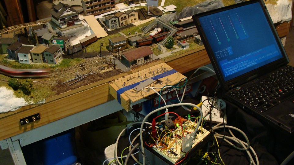
Once you've got your hardware setup, plug it into your PC and make sure the Arduino interface is all up-and-running, including the installation of the Arduino drivers. You can then go and download the latest version of CommandStationEX. Extract the zip and open the folder, you'll find the PDE is associated with the Arduino IDE and can just be double-clicked. Finally, just make sure your Arduino is configured correctly (type/port) in the IDE and upload the sketch.
Note that the software above is just the code for the Arduino. The Arduino acts as a bridge, with its own command set, so you'll then need a controlling application to get trains moving. I downloaded and extracted WebThrottle-EX, but you don't even have to do that! On the computer connected to the Arduino, just run it from the cloud!
Firstly, hit Connect in the top-right. It'll ask you to choose a Serial Port, which USB2Serial should be listed. Mine was COM6 and it all connected straight away. From there, hit the Power Switch in the middle. Finally, you need to enter the vehicle ID in the top left and then hit the arrow to the right of it. Thanks to my record keeping, I knew the ID I'd set the Kirara to. With the number 12 in place, I toggled the headlights button and the headlights came on! The track was dirty and the vehicle wheels were too, so I flipped it over to clean and found...
Hah! I left a note to myself that I hadn't even seen this time-around.
I didn't need N Scale to work this time around, so I packed it all up in ready for a HO DERM install! Mission accomplished!
DCC “Directional” Lighting without a Decoder
So, you have a 16-Car, 12-Car, 8-Car, 6-Car or 3-Car consist and you want to get the tail/head lights functioning correctly? Of course, you've already installed the expensive decoder in the engine car of the consist and if this is anything like all of the Japanese models I've dealt with, then it's somewhere in the middle and getting the power to the headlights is not really an option.
Ok, So companies like Kato have created smaller, feature-less decoders specifically for headlight and taillights in end cars... these are still the best option... the advantage to what I'm about to show you is that the lights will switch between backwards and forwards.
Anyway, if you can't, or are morally obliged not to, install the end-car decoders then you can cheat and install an AC/DC rectifier diode to 'fix' the direction of the train (and lights).
This, of course, means that the train you are going to install this into should really be only every traveling in one direction 'prototypically'. You'll be able to swap the end cars when you want the train to travel in the opposite direction, but this could be tedious and so it is entirely recommended this method only be used for consists where you intend on running them in one direction.
Micro Ace 6-Car "あいづ" KIHA 485系
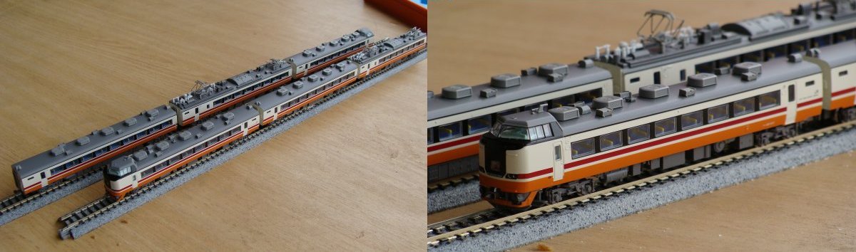
So, as you may have recently seen, I installed a decoder in my 6-Car "あいづ" KIHA 485系。 The engine car was number 3 of 6, so couldn't really get any further into the center... which is a good thing as it means it's nearly pushing as much as it has to pull.
So, I decided as I'd got it at a bargain price, that I wasn't going to fork out too much to make it DCC. I had the decoder in the engine car and wanted the lights to not 'buzz' and function correctly. I intended on having it running in one direction most of the time and could handle swapping the end cars if I wanted it to go the other way.
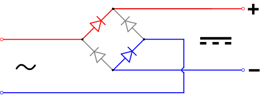
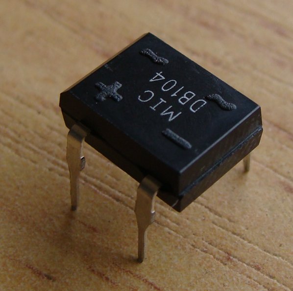
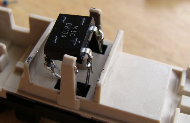
What this meant is that I would get an AC->DC Rectifier (0.84c at the local electronics store) to convert the AC voltage off the tracks to DC.
Once in DC voltage the polarity would be fixed... even if the car was swapped around on the rails.
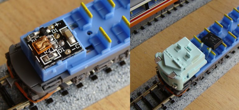
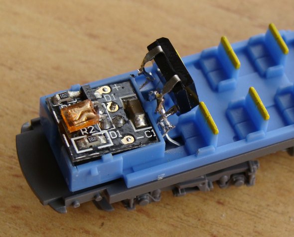
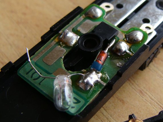
Right, so I removed the old lighting circuit board and bent the pins up that connected with the power rails... I then extended the AC side of the rectifier and pushed the pins into the area where the old contacts used to touch the power rails.
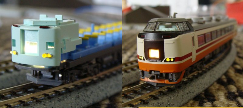
I then soldered up the DC output to the circuit board and threw it on the tracks to test.
Ok, this worked well... the lights even stayed on constantly after a bit of a wheel clean. Unfortunately, you now cannot 'shutdown' the train in a siding without cutting the power. The other issue now was that the rear car would have the 'Forward Lights' on as well if wired up directly... I therefore had to reverse the wiring after the DC output. I used my 0.25mm 'winding wire' for this.
And then a test...
And that was it... the train was DCC'd and ready to roll... It worked perfectly after this as well.
Twilight Express
I then quickly slapped a Rectifier in my Twilight Express end car and disabled the lighting in the car that sits right next to the engine.
To my surprise... a 12v BULB!... This must been an older set as Martjin had previously mentioned.
...and that was a wrap... yes, it's a mighty cop-out... and those who wish to have functional/switchable head/tail lights should not do this, but it does work and I must admit, does the job for my kinda running (Full Steam Ahead!)
Micro Ace 485 Series “あいづ” 6-Car Decoder Install
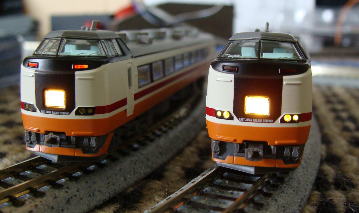
I found this for sale on eBay and, although it's JR East, I decided I could do with another 6-Car set.
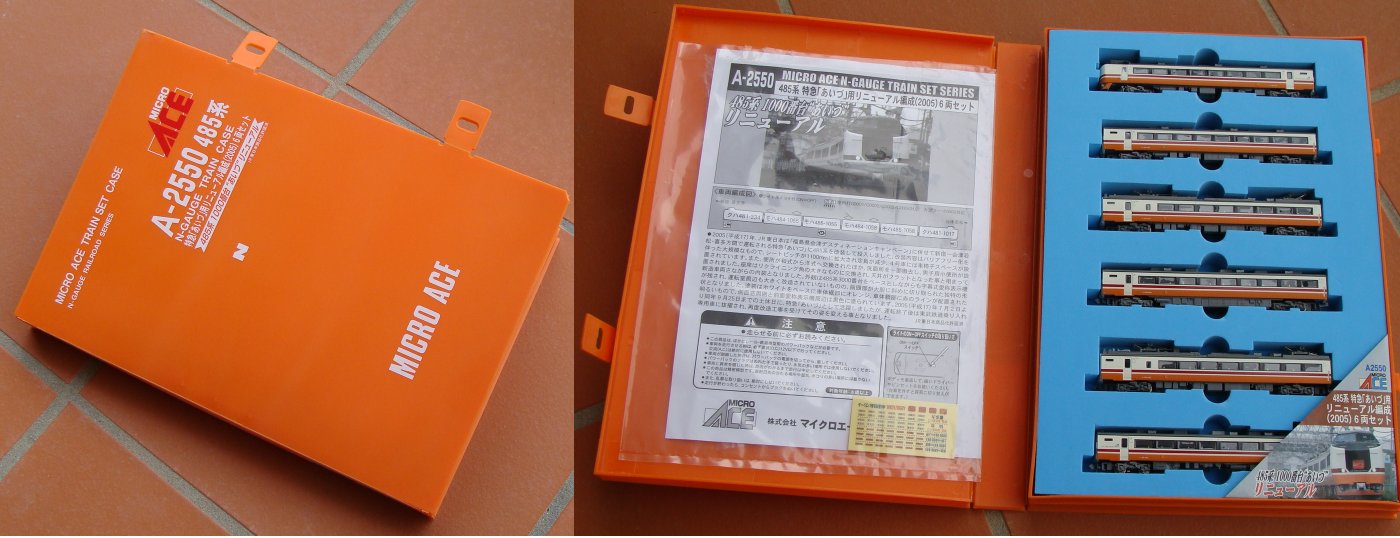
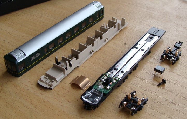
Being my first Micro Ace product, I was extremely impressed with the level of detail. I was also extremely impressed with the electronics on the inside and the way everything just snaps together... of course, this is the same with the greater majority of Japanese model railway products... but this 6-Car set seemed much easier to pull apart.
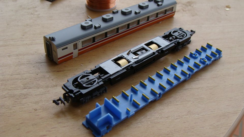
Once apart, it was obvious that the decoder install was going to be very easy... The motor contacts could easily be separated and the power rails were made of copper... solderable! After the copper wire was on.. the wire was lead back up alongside the copper rails to the decoder... wires were also soldered onto the rails to provide power. Finally, the decoder was installed.
Right... lighting... as per any large consist... there is usually a considerable length to the end cars for directional lighting... this usually means that people should install separate decoders in the end cars (high price!) or run wires throughout the cars (ugly!)... so instead, I decided to convert the AC current to DC and force the lights to be in specific directions...
But you'll see that in my next post!
DCC Booster Complete
Ladies and Gentlemen,
I am proud to finally announce that the Booster has been completed and tested.
The final design incorporates the following features:
- Short Circuit Protection with a ~6sec timeout when short detected.
- Two segments per booster rated at 2-3Amp each.
- These can be combined for a total output of ~5Amp.
- Status LEDs to indicate power output on each segment and also overload/short detection on each segment.
- Second Serial Port (DB9) on the rear panel to allow data connection to another booster.
A typical setup of the Booster would be as follows:
The Booster shown above was built in a readily-available Project Box and the next one built will probably not use the same model. I'll be going to the store on the weekend to see exactly what is available as the box used is a little larger than what is really required. Either way, if you still wanted one of these, now is the time to contact me.
Final PCB Board Complete!
Well, Silver Circuits manufactured and delivered my PCB much much quicker than expected and I'm not complaining!
And, last night, after a rush of construction... I couldn't get the board to work... The 'trip' sensors were permanently active! After a 30 minute stare at the circuit design today I'd realised I'd viewed an older circuit schematic when designing the PCB and had put the inputs to the LM339 the wrong way around!
After a quick test to correct this I had the booster operational.
Unfortunately this now means that all boards in this initial run are defective, but I have devised a way to correct the issue without too much hacking. A small veroboard piggy-backed on has allowed me to correct the inputs to the IC.
I was very much relieved once it was all operational. I now need to get the final components (you can see a dodgy-hack of resistors wired on) and the heatsinks in place. Then I'll need to find a neater box to mount it all in and all should be set to go.
PCB Design Complete
Well, after a long fight of finding appropriate software and then design I've finally sent off the final (if not entirely messy) design to the manufacturers...
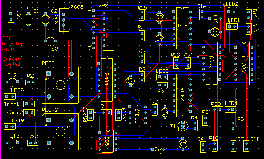
Sure, it's not as small as I would have liked... but it's all set in stone now. I should see 8pcs on my doorstep in around a fortnight and then I can finally produce a finished product.
I can't wait actually... Last weekend I tested the final prototype on my own layout... which really only allows for around 3 trains running (one on a branch, one stuck in a siding and one on the main) and my battery ran out on the laptop before I had a chance to fully test it all out... either way, the quick test ran perfectly on all accounts:
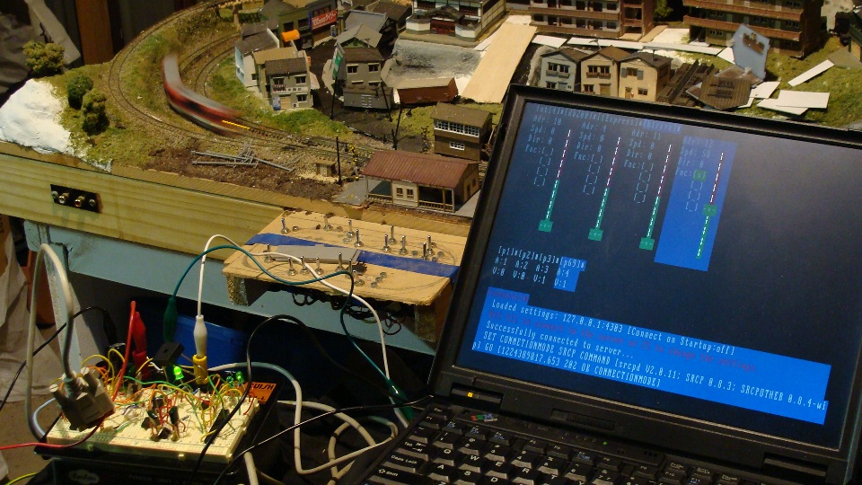
I also purchased two DCC Accessory Decoders from eBay. I coded those in to trainControl (you'll see a few little squares above the console messages and below the train throttles) and they work great. Unfortunately they cannot be wired directly to the Kato UniTrack points (you'll need to wire a few relays in between) but I'm told work well on the Peco points. I didn't get to test them at the time.
The DCC Accessory Decoders did require me to do a bit of fine tuning on the Booster circuit though; it turns out they suck quite a bit of current on power-up to charge their little capacitors. This meant that the initial current draw on the booster was exceeding the trip circuit and the whole system would not power on.
After a little help the 1K2 resistor providing the op-amp comparison voltage was incremented to a 1K4 and everything worked fine.
This made me realise that the circuit will have different requirements for different layouts and so the final design will now incorporate a trimpot (initially set to 1K4) that can be user adjustable [but WILL void warranty] for 'expert users' to adjust.
Anyway... the work continues... everything is now set. I'm quite proud of the entire system and I can't wait to see the final circuit boards!
UPDATE: The boards are already done and on their way (priority) to me... thanks to Silver Circuits!
DCC Booster Prototype Mark II
Ok, hot off the development floor is the Booster Prototype 2.
This now includes short-circuit protection! The final design will have 2 outputs (for two separate segments of track) at 3 Amp each (depending on power supply capabilities.) There are also now 4 status LEDs (Supply Power, Data, Overload, Track Power/Data)... More to come as I finalise the circuit board design.
Eizan Dentetsu (叡山電鉄) Kirara 900 Decoder Install
I'd bought both the Maple Red and Maple Orange versions of this EMU back in 2006 when I first went to Japan and have always loved the quality and performance.
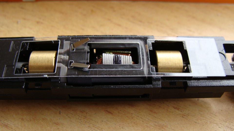
Since the latest trend has been to DCC all my gear, I had decided that what better candidate next than to do one of these up. It was all quite simple too. The 'power rails' run down each side (internally) of the chassis and after isolating these from the engine I soldered the decoder in.
Firstly I took the thing to bits... I love Kato and their use of clips... everything snaps apart, but you really need to be careful! I nearly broke one clip underneath as you have to squeeze them with a fair bit of force.
After disembowing the engine I soldered it directly to the Decoder as I could easily put it back without having to worry about where the wires ran.
Putting it back in was easy and the next step was to wire up the main power to the copper rails.
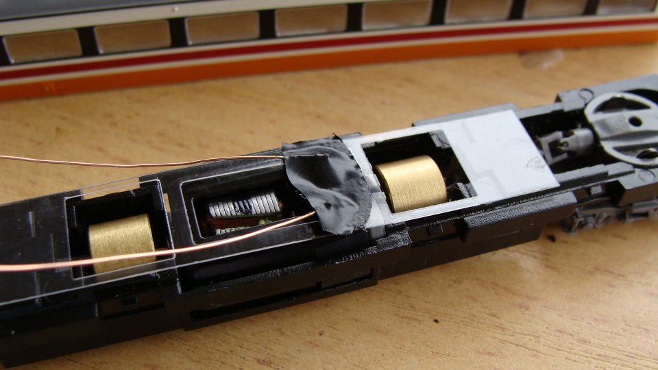
There's a pair of LEDs (Red/Orange) at either end and they're wired up in parallel where one is reversed to allow them to switch between reverse/forward marker lights. This of course, wont work with DCC as you now have one common (single polarity) wire and then two rev/fwd wires... so I ripped one LED out of the board, flipped it around and then had my common.
I then used some very fine-gauge 'winding wire' (used for transformers/magnets) to connect the LEDs up (there was already a resistor in the circuit) since the thicker decoder wiring wouldn't fit under the light shield. To get the lights in the rear trailer working I ran this wire all the way between the trailers and to the other board, resoldering it in the same way.
I also ran an extra two wires from the 'power rails' in the trailer to the rails in the motor car. Therefore ALL 4 bogies were wired for power pickup and the thing ran like a dream (initially it was a bit sloppy with only the 2 power car bogies picking up the power.)
After programming it to use address 12, it was set to go. Next is to do my Maple Orange. ...actually, I'll get back to the programming first... I want to have my app able to at least set the addresses on decoders.
trainControl evolves…
After a few more days of work the trainControl application has evolved further:
Notable features:
- Loading and saving of trains/connection config
- Resizable
- Add/Delete trains via interface
- Connect/Disconnect on the fly
Still more to go... but very functional now... Download the source here. Of course, be warned! ... The source is constantly being updated by me and may DESTROY your computer. I've also considered the next challenge on this project... Handheld control via a GamePark GP2x.
trainControl v0.1 created!
After 3 days of coding/learning/coding-again I managed to whip together a fairly usable *nix console application to control the DCC System.
It is a client for the srcpd service mentioned previously and can control any number of trains.
There's still a fair bit of work to do on it... dynamically resizing windows, mouse input, etc... but I thought I'd post to show some progress.
If anyone is interested the source is here and can be compiled with gcc -o tc main.c -lncurses -lform -lpanel
...work continues...
Random Photos
Search
Tags
Links - Click for details
- Abandoned Rails (Japan)
- AIRLINE (Shinkansen Photography)
- Akihabara Station
- annexpressのブログ
- Australian Model Railway Magazine
- DCC普及協会ホームページ (Japanese DCC)
- Dead Section (Japanese Track Diagrams)
- Delicious Things (Japanese N Scale DCC)
- Densha Wotorou
- Digital Direct for Windows (DCC Server)
- Don's Dream World – AMAZING N Scale Japanese Layout
- Hatena::Diary
- Japanese N-Scale Modeling Forum
- JR Chiisai
- Kaz-T's blog レインボーライン (Rainbow Line)
- LED Resitance Calculator
- Masioka
- Poppondetta Blog
- RailFan Magazine, Japan
- Railmind
- Railway Travelers' Room
- Serenity Valley
- Shashinka Ichiban
- Shuzuku
- Sumida Crossing
- The next station is…
- Tomix N Gauge Track and Japanese N Gauge Trains
- TT Forums (Transport Tycoon Deluxe)
- 名鉄尾西線の貨物列車 (Nagoya: Meitetsu Freight)
- 日本型Nゲージ DCC改造例のご紹介 (Okiraku DCC)
- 泰 茅 轍 道 (Taichi Railway)
- 箱庭登山鉄道製作記 (Hakone-Tozan Layout Blog)
Archive
- May 2026
- April 2026
- March 2026
- February 2026
- January 2026
- November 2025
- October 2025
- September 2025
- August 2025
- July 2025
- June 2025
- February 2025
- January 2025
- November 2024
- September 2024
- August 2024
- July 2024
- June 2024
- May 2024
- April 2024
- March 2024
- February 2024
- December 2023
- October 2023
- September 2023
- August 2023
- July 2023
- June 2023
- May 2023
- April 2023
- March 2023
- December 2022
- November 2022
- October 2022
- April 2022
- March 2022
- February 2022
- January 2022
- December 2021
- November 2021
- September 2021
- August 2021
- July 2021
- May 2021
- March 2021
- February 2021
- January 2021
- October 2020
- September 2020
- August 2020
- July 2020
- June 2020
- May 2020
- April 2020
- March 2020
- January 2020
- December 2019
- November 2019
- October 2019
- September 2019
- August 2019
- July 2019
- June 2019
- April 2019
- March 2019
- February 2019
- January 2019
- December 2018
- November 2018
- October 2018
- September 2018
- August 2018
- July 2018
- June 2018
- May 2018
- April 2018
- March 2018
- January 2018
- December 2017
- November 2017
- October 2017
- September 2017
- August 2017
- July 2017
- June 2017
- May 2017
- March 2017
- February 2017
- January 2017
- December 2016
- November 2016
- October 2016
- September 2016
- August 2016
- July 2016
- June 2016
- May 2016
- February 2016
- November 2015
- October 2015
- September 2015
- August 2015
- July 2015
- June 2015
- May 2015
- April 2015
- March 2015
- February 2015
- January 2015
- December 2014
- November 2014
- August 2014
- July 2014
- May 2014
- April 2014
- March 2014
- December 2013
- November 2013
- October 2013
- June 2013
- August 2012
- April 2012
- March 2012
- February 2012
- November 2011
- October 2011
- September 2011
- July 2011
- June 2011
- May 2011
- April 2011
- March 2011
- February 2011
- January 2011
- December 2010
- November 2010
- October 2010
- September 2010
- August 2010
- June 2010
- May 2010
- April 2010
- March 2010
- February 2010
- January 2010
- December 2009
- November 2009
- October 2009
- August 2009
- January 2009
- December 2008
- November 2008
- October 2008
- September 2008
- July 2008