


 Melbourne BG SCS Train Timetable


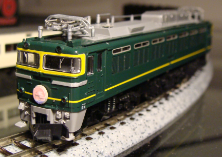
EF81 (Twilight Express) Marker Lights
Well, after a successful Decoder + Headlight install I thought I'd attempt to get the reverse marker lights going as well. I'd been told on the JNS forums that these lights are used very rarely in Japan and that explained why the model manufacturers (in this case Tomix) didn't bother to put lights behind them. Despite this there is a 'tube' of clear, but red, plastic behind the marker lights and this means that I would only have to get an LED lined up behind it to get them to work.
So, I went down to the local electronics store and looked for the smallest LEDs I could find...
... and I tell you what, they're tiny... I used the 'helping hands' aligator clips to get the soldering done and initially attempted to wire in one LED behind the lights.
The next issue was wiring... I first used thin insulated wire I'd stolen out of a broken toy shotgun (with laser sight)... and this was OK, but there was starting to be too much piling up on top of the chassis and causing headaches when trying to put the shell back on.
Then I found 'winding wire' for building electromagnets and transformers and this stuff did the trick perfectly! This worked OK, but I could only ever get the brightness I wanted behind one of the lights. Since I wanted to be even I chose to put two lights in there.
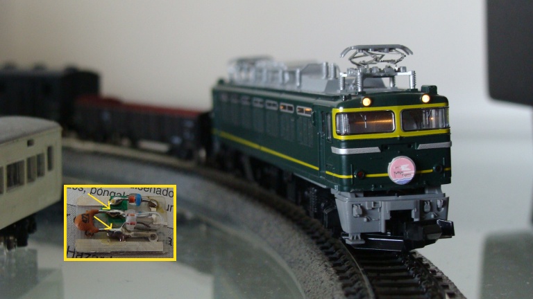
After a little electrical tape for insulation and some blu-tac for positioning I had what I found to be success :)
There's a few issues... like the lights moving when you remove/replace the shell... but once it's all together they look great...
...the light seen on coming through underneath isn't really visible in normal conditions... my camera just decided to extend the exposure. Anyway, one end done... the other is still to do.
EF81 (Twilight Express) DCC Decoder Install
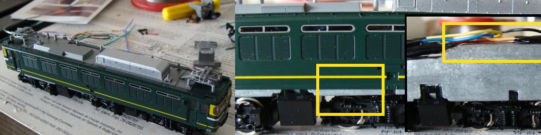
Well... This wasn't anywhere near as easy as I was hoping... The Japanese really know how to use every last bit of space in their models and although the full-metal chassis adds a nice amount of weight for smooth running, it is hell when trying to make room for a decoder.
Anyway, that said, everything is in and functioning... there is just a little more to do on making the shell fit back on properly... and a little more to do on lighting. Out of the box, the locomotive does not have reverse marker lights... just the top front headlights. So I'll be purchasing some 3mm red LEDs tomorrow to fix this situation (there is just enough room to install them.)
So, after dismantling the locomotive, reality hit me when I realised how little room there was inside. The chassis is a two-part construction with each side conducting either negative or positive. This was bad... the power came directly off the bogies and into the chassis and then straight to the bushes on the motor. I had to insulate this somehow and get wires in there. I managed to drill through the soft metal chassis and then solder on to the bushes (There are actually removable contacts that slide on, of which I soldered to.)
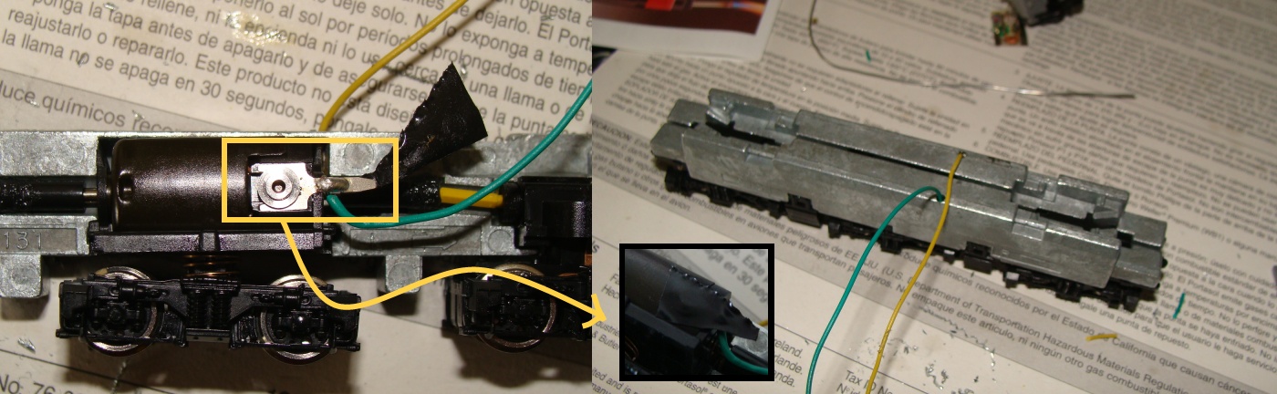
In the picture above you can see that the chassis fills the entire shell and there is only a few chunks missing where the headlights go. Since I no longer needed the diode/capacitor combo for the original headlights, I could remove the board and use one of the spaces for the decoder.
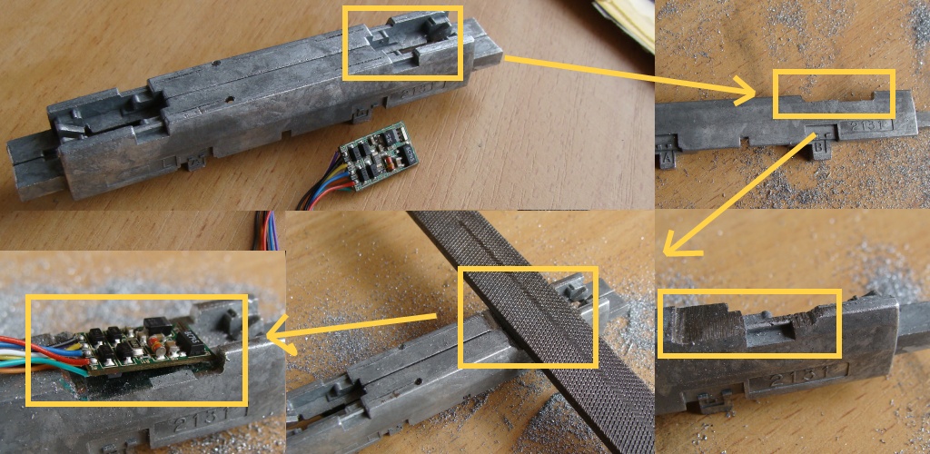
I went and bought a set of files and got to work at hacking out a space for it to go. After I'd removed enough I decided to quickly tape up the wiring and decoder and attempt to run it...
Well, no problems here... the locomotive ran like a charm... at some very very slow crawls! The Hornby 8215 decoders (although cheap) contain the back emf technology for really low and strong speeds.
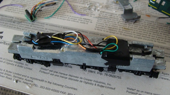
So, the next step was lighting... I unsoldered the original 12v globes from their boards and wired them directly to the decoder... they then were taped in place where they used to sit.
There was not much room at all near the decoder, as it had taken the spot of the previous light. In the end it's still too tight and there needs to be a little more room made (more filing.)
These locomotives were not fitted stock with reverse marker lights! They have the clear plastic inside and just enough room to hold a small globe to light them... so I haven't completed this yet until I get them working...
And then I need to find the carriage set for the my Twilight to pull :)
Prototype Booster Complete!
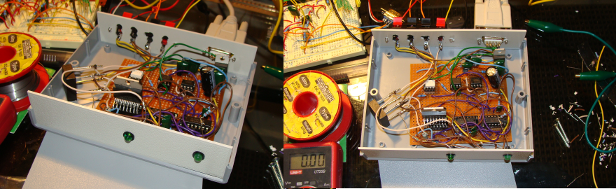
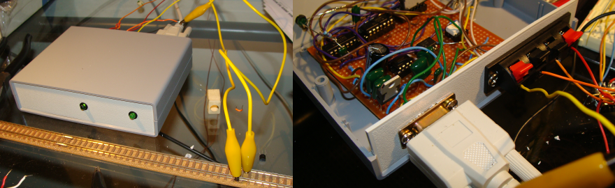
Well... after a night of work (and using my breadboard version as basis) of soldering and drilling I have a prototype! I've used off-the-shelf components to house the board and everything fits nicely... secure... and works perfectly.
The next version will have an override switch (since the current version will only activate when there is data on the serial port) to allow power all the time.
Now is time to use this version as a test for how many amps it can push out... note I'm still using my computer power supply (which is still powering this machine I'm surfing on!) and all is well.
Finally... The going price for one of these will be AUD$65.00.
Anyone wanting one can leave a comment on this post or email me at stevenhoefel at hotmail dot com.
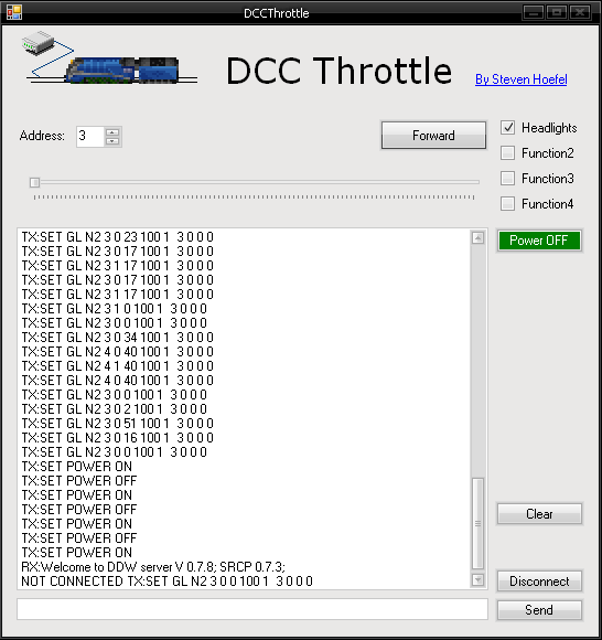
I've also written a new client app... very basic... controls the train that you specify.
Odoriko 185 Series Decoder Install
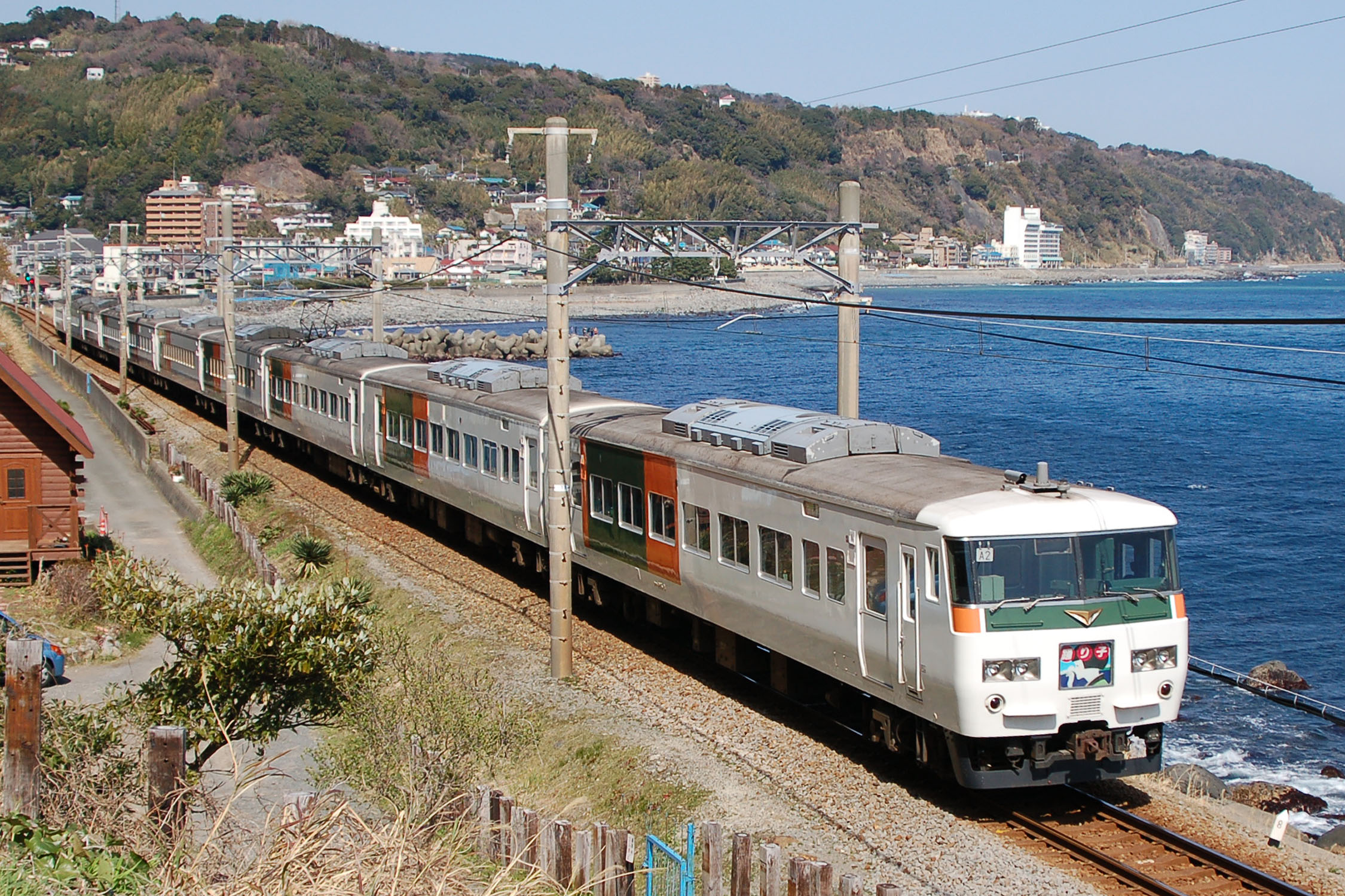
[From Wikipedia:]The Odoriko (踊り子?) is a limited express train service in Japan operated by JR East which runs between Tokyo and Izukyū-Shimoda or Shuzenji.
The limited express service was inaugurated in October 1981 following the introduction of the then-new 185 series EMUs, replacing the earlier Izu express services from Tokyo to Izu. Services are currently operated by 7-, 10-, and 10+5-car 185 series EMUs, making it the longest Limited Express train running in Japan (excluding shinkansen trains).
The word odoriko means a girl dancer in Japanese. The train service was named after the title of novel Izu no Odoriko (The Dancing Girl of Izu) by Yasunari Kawabata. The stage of the novel is the destination of the train, Izu Peninsula.
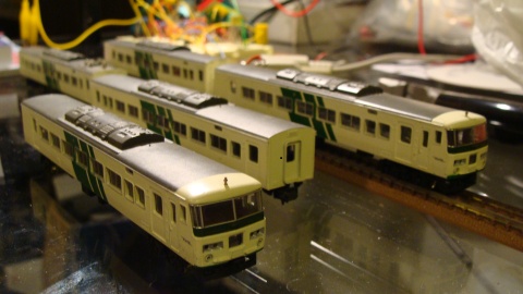
I'd bought my 5-Car Micro Ace Set partially damaged (if anyone can tell me where to get replacement pantographs?) and had opened it up on the first night of running due to severe eletrical issues.
After a night with WD-40 and a soldering iron I had the set doing laps at good speed, but every other day it needed a service.
This all boiled down to the way the motor car connects to the tracks. The bogies both conduct both polarities into the chassis which is split in two and electrically isolated. Unfortunately at the point where the bogies touch the chassis was a lot of grime and damaged parts. It seems there were originally two pins that had been snapped meaning the bogies were very loose.
Anyway... all this meant that the electrical connection in the motor car was next to useless since a constant power source was required for DCC and interruptions would play havoc on the data stream from the rails.
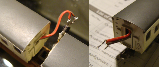
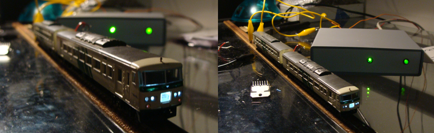
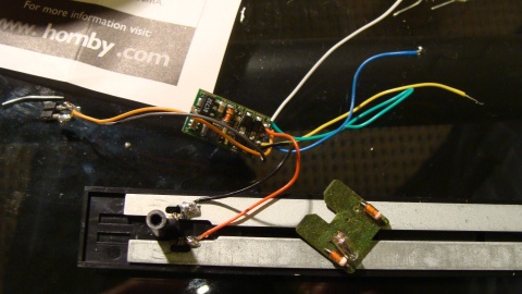
I therefore decided that the best method was to slap the decoder in the end car (meant easier wiring of one set of headlights) and have a tiny cable run through (with a plug) to the motor car... This all went fairly smoothly... but I did have to remove the seating in the end car... I'll look into this again shortly.
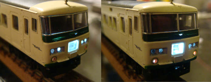
I removed the 12v globes that originally lit up the car with white LEDs and around 1K2 total resistance to get the level of light emitted in the photo below. This was simply two 680ohm resistors in series to the anodes of both LEDs connected to the Blue wire from the decoder. The cathodes connected directly to the Yellow and White wires for forward and reverse. I initially wanted to use the original light circuit but found that bending LEDs to fit in there would be too tight.
Anyway... the end result is a beautifully running 5 car set with directional headlights at one end and to-be-completed headlights at the other end... should I run wires right through all 5 cars or buy another decoder just for 2 LEDs? ...
Researching a DCC booster circuit and DCC computer control
Ok, after a miriad of attempts to control my model railroads with computers (parallel port to relays, voltage controls, etc...) I decided it was time to go to DCC... I mean... why not use the rails as a data bus and have all the logic inside the locomotives themselves. I had decided that all the european command stations were too expensive and that I would do as some of the references below have done and just use my computer to push out the 1's and 0's. Anyway, after a lot of trial and error I have a working prototype... but stay tuned for something more production ready.
For starters, here are some good references on homegrown DCC Boosters:
- The DCC Wiki
- Michael Brandt's Site on DCC
- Rod Murgatroyd's Booster (And other circuits)
- Haba's Booster
- Mr Paisley's Booster
After searching online electronic stores for parts, I had noticed that there were two basic circuits in use. One used the L298 H Bridge and the other the LMD18200. As I'd browsed across Michael Brandt's site first, I'd realised that it was only necessary to connect a booster to the computer (and Haba's site confirmed this). Although I'd purchased all the components to make the Parallel port logic board, I've still never actually constructed it since it was much easier to just go direct to the COM1 (and also skip all the assembler programming!).
One weekend-long of wiring and re-wiring produced this... It's recommended to build anything like this first on a breadboard as you get the opportunity to just rip it all back out again when you make mistakes... and after a lot of cooked components and other issues... I finally got it all to work. The circuit uses a 12vAC input but I just skipped the initial AC-DC regulator and used the 12vDC from my computer's power supply. This currently allows around 8vDC to the engine and so I'll be upgrading to something closer to 18vDC input when I get the chance... For now, and it's great for testing, it's better to have lower voltages.
Next, Software...
There are a few options here... many in German and many in Linux. I'd found DDL and realised this was the way to go. It is what Haba had been running and therefore must work. I had severe issues compiling it on debian since the code was old and am still not across C/C++ enough to have gotten it going. I then found the binaries and managed to get something running, although couldn't successfully get a connection. (This was also whilst I was using Rod's circuit and so there could well have been too many variables...)
I then hit gold with DDW (DDL for Windows!). I had a few initial problems working out which port COM1 was and then why there was no action... but once my booster was complete and connected everything just started going... I realised that the server alone is no good... it wont send out data without a client connected... client of choice being RailyPlan v2.0 found on theDDW download page.
Now, I'd bought 2 Hornby R8215 Decoders and, based on forums read online, there seems to have been NRMA DCC compatability issues... Let me tell you that these things are gold. They are tiny, cheap and reliable. I've cooked one quite well and it keeps going... it has even emitted the usual burning-silicon smell a few times (when the motor has shorted) and keeps going. The only issue I've had is that the wires unsolder themselves when it gets tooooo hot. :)
The first decoder was installed in my old-reliable German DB loco (model unknown) and it was too easy. Plastic chassis, minimal wiring... simply spliced in. The decoder defaulted to Address '3' and I had it running in no time. Had no headlights or anything else to wire up, so there was no test of functions, etc... here.
This engine ended up being the old-reliable for a very long time for testing purposes of software, etc... that I was about to write. I believe I'm about to realise how easy this first loco install was compared to the little space that exists in Japanese n-scale engines.
I'm currently in the process of Decoder-ing up my Odoriko 5-Car series and will post again once I have the final story.
What a mess... you can see the breadboard up the back being powered by the computer power supply under the desk and my straight run of track.
Random Photos
Search
Tags
Ads
Links - Click for details
- Abandoned Rails (Japan)
- AIRLINE (Shinkansen Photography)
- Akihabara Station
- annexpressのブログ
- Australian Model Railway Magazine
- DCC普及協会ホームページ (Japanese DCC)
- Dead Section (Japanese Track Diagrams)
- Delicious Things (Japanese N Scale DCC)
- Densha Wotorou
- Digital Direct for Windows (DCC Server)
- Don's Dream World – AMAZING N Scale Japanese Layout
- Hatena::Diary
- Japanese N-Scale Modeling Forum
- JR Chiisai
- Kaz-T's blog レインボーライン (Rainbow Line)
- LED Resitance Calculator
- Masioka
- Poppondetta Blog
- RailFan Magazine, Japan
- Railmind
- Railway Travelers' Room
- Serenity Valley
- Shashinka Ichiban
- Shuzuku
- Sumida Crossing
- The next station is…
- Tomix N Gauge Track and Japanese N Gauge Trains
- TT Forums (Transport Tycoon Deluxe)
- 名鉄尾西線の貨物列車 (Nagoya: Meitetsu Freight)
- 日本型Nゲージ DCC改造例のご紹介 (Okiraku DCC)
- 泰 茅 轍 道 (Taichi Railway)
- 箱庭登山鉄道製作記 (Hakone-Tozan Layout Blog)
Archive
- June 2025
- February 2025
- January 2025
- November 2024
- September 2024
- August 2024
- July 2024
- June 2024
- May 2024
- April 2024
- March 2024
- February 2024
- December 2023
- October 2023
- September 2023
- August 2023
- July 2023
- June 2023
- May 2023
- April 2023
- March 2023
- December 2022
- November 2022
- October 2022
- April 2022
- March 2022
- February 2022
- January 2022
- December 2021
- November 2021
- September 2021
- August 2021
- July 2021
- May 2021
- March 2021
- February 2021
- January 2021
- October 2020
- September 2020
- August 2020
- July 2020
- June 2020
- May 2020
- April 2020
- March 2020
- January 2020
- December 2019
- November 2019
- October 2019
- September 2019
- August 2019
- July 2019
- June 2019
- April 2019
- March 2019
- February 2019
- January 2019
- December 2018
- November 2018
- October 2018
- September 2018
- August 2018
- July 2018
- June 2018
- May 2018
- April 2018
- March 2018
- January 2018
- December 2017
- November 2017
- October 2017
- September 2017
- August 2017
- July 2017
- June 2017
- May 2017
- March 2017
- February 2017
- January 2017
- December 2016
- November 2016
- October 2016
- September 2016
- August 2016
- July 2016
- June 2016
- May 2016
- February 2016
- November 2015
- October 2015
- September 2015
- August 2015
- July 2015
- June 2015
- May 2015
- April 2015
- March 2015
- February 2015
- January 2015
- December 2014
- November 2014
- August 2014
- July 2014
- May 2014
- April 2014
- March 2014
- December 2013
- November 2013
- October 2013
- June 2013
- August 2012
- April 2012
- March 2012
- February 2012
- November 2011
- October 2011
- September 2011
- July 2011
- June 2011
- May 2011
- April 2011
- March 2011
- February 2011
- January 2011
- December 2010
- November 2010
- October 2010
- September 2010
- August 2010
- June 2010
- May 2010
- April 2010
- March 2010
- February 2010
- January 2010
- December 2009
- November 2009
- October 2009
- August 2009
- January 2009
- December 2008
- November 2008
- October 2008
- September 2008
- July 2008