


 Melbourne BG SCS Train Timetable


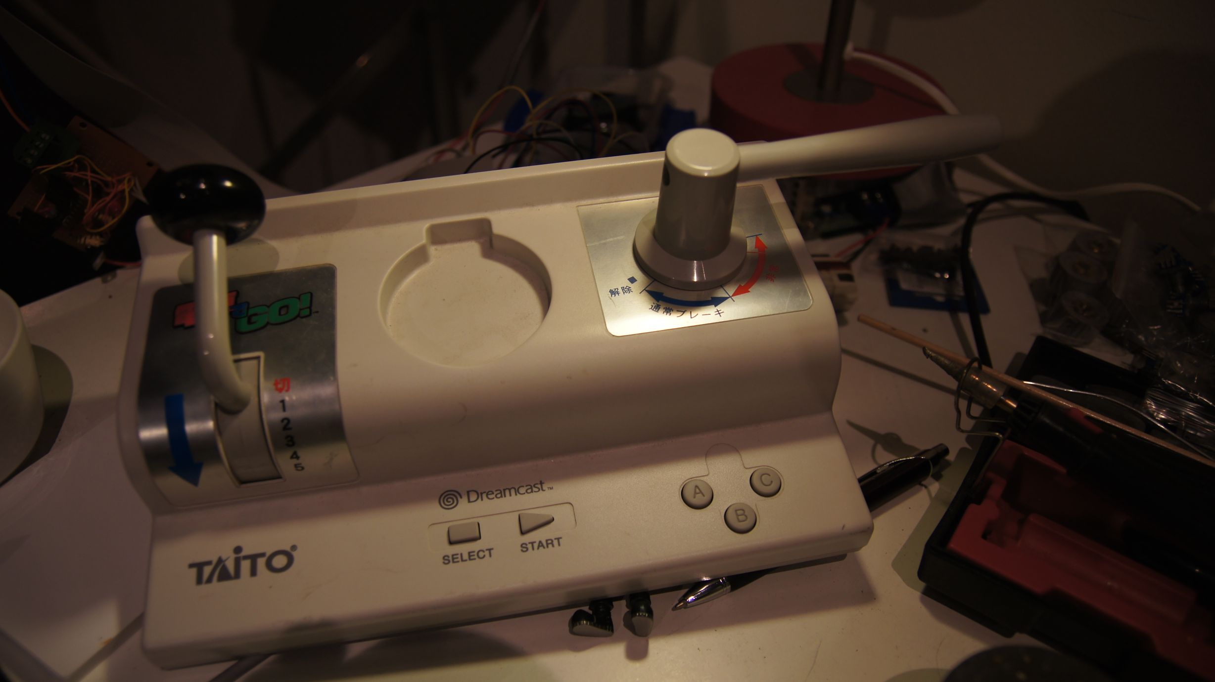
Arduino + Dreamcast Densha-De-Go Controller
I've had Densha-De-Go and the controller for the Dreamcast for a while now... I'd even invested a few hours in playing the actual game, but the accuracy required is crazy. Supposedly in Japan it's that realistic that even real train drivers have a hard time getting it spot on :)
Anyway, I'd wanted to get this going for train control for a while after managing to make a Wii Nunchuck control my trains.
You can find more information on the controller at SEGA Retro, SEGAGAGA Domain, Wikipedia, Play Asia and genki Video Games.
Previous attempts
Quite a few months ago I spent a few hours with my Densha-De-Go controller and my Arduino Mega in an attempt to get them to communicate. The goal was to be able to read the controller and then use it to control my model railroad. Unfortunately, I was doing this blind, running off information from Marcus Comstedt's 'Dreamcast Programming' site; specifically his breakdown of the Maple Bus Protocol.
I ended up with nothing working and sent out a few pleas for help on the Arduino forum and to Marcus himself. I received information regarding the fact that it should work (the Arduino had the horsepower), but I would have to ensure the timing was intricate and that the Arduino was always ready to receive data.
I then posted to the Arduino Forum for help. A few months later WzDD came to my rescue with word that he had successfully made the Arduino communicate with a Dreamcast Controller. I hadn't had much time up until now to work on this, and WzDD hadn't done any further work on it, so I took it that he just wanted to prove the concept and that I'd have to get off my backside to make things progress further. In the end, I did want to get my controller functioning.
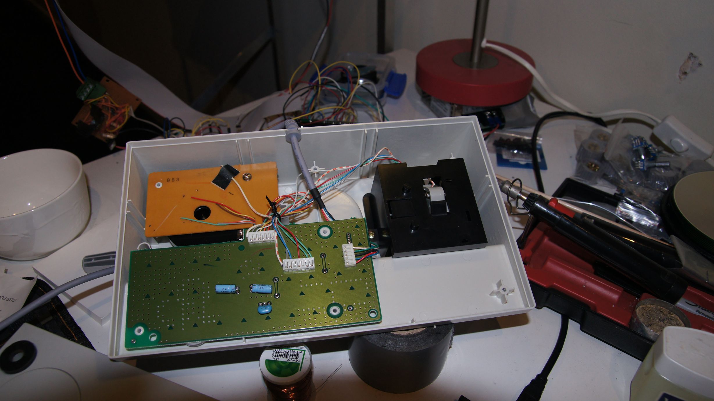
I had previously had everything I needed to test this again, so I gave it another go. My previous setup was a cut-in-half Dreamcast controller extension cable and my Densha-De-Go controller. The extension cable meant I didn't have to hack around with the actual controller or port imitation.
Getting set up...
Due to the requirement to use assembler for the actual low-level controller interactions, we cannot use the Arduino IDE and must use WinAVR (or just avrdude on Linux.) Download this from here (select the latest version) and install to the default directory.
You then need to download the arduino-maple source code and extract somewhere locally. I've put the folder on C:\arduino-maple\.
Open Programmers Notepad [WinAVR] from the start menu and then open the arduino-maple.cpp file from where it has been extracted. (C:\arduino-maple\arduino-maple.cpp in my case.)
If all is installed correctly, then you should be able to choose Tools - [WinAVR] Make All and have the following output in the output window:
> "make.exe" all
avr-gcc -Wall -g2 -gstabs -Os -fpack-struct -fshort-enums -ffunction-sections -fdata-sections -ffreestanding -funsigned-char -funsigned-bitfields -mmcu=atmega328p -DF_CPU=16000000UL -I./arduino -c arduino/pins_arduino.c -o build/arduino/pins_arduino.o
In file included from arduino/wiring_private.h:30,
                 from arduino/pins_arduino.c:26:
c:/winavr-20100110/lib/gcc/../../avr/include/avr/delay.h:36:2: warning: #warning "This file has been moved to <util/delay.h>."
...
Lots of warnings, no errors...
...
avr-g++ -Os -Wl,-gc-sections -mmcu=atmega328p  build/arduino/pins_arduino.o build/arduino/WInterrupts.o build/arduino/wiring.o build/arduino/wiring_analog.o build/arduino/wiring_digital.o build/arduino/wiring_pulse.o build/arduino/wiring_shift.o build/./arduino-maple.o build/arduino/HardwareSerial.o build/arduino/Print.o build/arduino/Tone.o build/arduino/WMath.o build/arduino/WString.o build/./libmaple.o -o app.elf
avr-objcopy -R .eeprom -O ihex app.elf  app.hex
avr-size --format=avr --mcu=atmega328p app.elf
AVR Memory Usage
----------------
Device: atmega328p

Program:    3380 bytes (10.3% Full)
(.text + .data + .bootloader)

Data:        796 bytes (38.9% Full)
(.data + .bss + .noinit)

> Process Exit Code: 0
> Time Taken: 00:02
Now, as you can see above... that's not my Arduino! I have an Arduino Mega and therefore we need to adjust the Makefile correctly for my setup. Here you'll need to know the CPU code, interface type and the port number. Also make sure you change the upload task to program so that we can use the menu items in WinAVR.
# Makefile for building small AVR executables, supports C and C++ code
# Author: Kiril Zyapkov
# Hacked up by nfd

SOURCE_DIRS = . arduino
INCLUDE_DIRS = arduino
MMCU = atmega1280
F_CPU = 16000000UL
SRC_ROOT = .
BUILD_DIR = build

CFLAGS = -Wall -g2 -gstabs -Os -fpack-struct -fshort-enums -ffunction-sections \
 -fdata-sections -ffreestanding -funsigned-char -funsigned-bitfields \
 -mmcu=$(MMCU) -DF_CPU=$(F_CPU) $(INCLUDE_DIRS:%=-I$(SRC_ROOT)/%)

CXXFLAGS = -Wall -g2 -gstabs -Os -fpack-struct -fshort-enums -ffunction-sections \
 -fdata-sections -ffreestanding -funsigned-char -funsigned-bitfields \
 -fno-exceptions -mmcu=$(MMCU) -DF_CPU=$(F_CPU) $(INCLUDE_DIRS:%=-I$(SRC_ROOT)/%)

LDFLAGS = -Os -Wl,-gc-sections -mmcu=$(MMCU) #-Wl,--relax

TARGET = $(notdir $(realpath $(SRC_ROOT)))
CC = avr-gcc
CXX = avr-g++
OBJCOPY = avr-objcopy
OBJDUMP = avr-objdump
AR  = avr-ar
SIZE = avr-size

SRC = $(wildcard $(SOURCE_DIRS:%=$(SRC_ROOT)/%/*.c))

CXXSRC = $(wildcard $(SOURCE_DIRS:%=$(SRC_ROOT)/%/*.cpp))

ASMSRC = $(wildcard $(SOURCE_DIRS:%=$(SRC_ROOT)/%/*.S))

OBJ = $(SRC:$(SRC_ROOT)/%.c=$(BUILD_DIR)/%.o) $(CXXSRC:$(SRC_ROOT)/%.cpp=$(BUILD_DIR)/%.o) $(ASMSRC:$(SRC_ROOT)/%.S=$(BUILD_DIR)/%.o)

DEPS = $(OBJ:%.o=%.d)

$(BUILD_DIR)/%.o: $(SRC_ROOT)/%.c
	$(CC) $(CFLAGS) -c $< -o $@

$(BUILD_DIR)/%.o: $(SRC_ROOT)/%.S
	$(CC) $(CFLAGS) -c $< -o $@

$(BUILD_DIR)/%.o: $(SRC_ROOT)/%.cpp
	$(CXX) $(CXXFLAGS) -c $< -o $@

all: app.hex printsize

#$(TARGET).a: $(OBJ)
#	$(AR) rcs $(TARGET).a $?

app.elf: $(OBJ)
	$(CXX) $(LDFLAGS) $(OBJ) -o $@

$(BUILD_DIR)/%.d: $(SRC_ROOT)/%.c
	mkdir -p $(dir $@)
	$(CC) $(CFLAGS) -MM -MF $@ $<

$(BUILD_DIR)/%.d: $(SRC_ROOT)/%.cpp
	mkdir -p $(dir $@)
	$(CXX) $(CXXFLAGS) -MM -MF $@ $<

#$(TARGET).elf: $(TARGET).a
#	$(CXX) $(LDFLAGS) $< -o $@

app.hex: app.elf
	$(OBJCOPY) -R .eeprom -O ihex $<  $@


clean:
	echo $(RM) $(DEPS) $(OBJ) $(TARGET).*

printsize:
	avr-size --format=avr --mcu=$(MMCU) app.elf

# Programming support using avrdude. Settings and variables.
PORT = /dev/tty.usbserial-A700ekGi
#PORT = /dev/ttyUSB0
AVRDUDE_PORT = com3
AVRDUDE_WRITE_FLASH = -U flash:w:app.hex
MCU = atmega1280
AVRDUDE_PROGRAMMER = stk500v1
#AVRDUDE_FLAGS = -V -F -C \app\arduino-0021\hardware\tools\avr\etc\avrdude.conf
AVRDUDE_FLAGS = -V -F \
-p $(MCU) -P $(AVRDUDE_PORT) -c $(AVRDUDE_PROGRAMMER) \
-b $(UPLOAD_RATE)
UPLOAD_RATE = 57600
#
# Program the device.
INSTALL_DIR = \app\arduino-0021
AVRDUDE = avrdude
program: app.hex
	#python pulsedtr.py $(PORT)
	$(AVRDUDE) $(AVRDUDE_FLAGS) $(AVRDUDE_WRITE_FLASH)
The first line in the program target (Line 93) 'pushes' the reset button on the Arduino. As we don't have Python installed we have to do this manually. So, build the source code via the [WinAVR] Make All and ensure there are no errors. Now press the 'reset' button on the Arduino and then quickly choose Tools - [WinAVR] Program. If all goes correctly then you'll see the code uploading to your Arduino:
#python pulsedtr.py /dev/tty.usbserial-A700ekGi
avrdude -V -F -p atmega1280 -P com3 -c stk500v1 -b 57600 -U flash:w:app.hex
avrdude: AVR device initialized and ready to accept instructions

Reading | ################################################## | 100% 0.05s

avrdude: Device signature = 0x1e9703
avrdude: NOTE: FLASH memory has been specified, an erase cycle will be performed
         To disable this feature, specify the -D option.
avrdude: erasing chip
avrdude: reading input file "app.hex"
avrdude: input file app.hex auto detected as Intel Hex
avrdude: writing flash (3508 bytes):

Writing | ################################################## | 100% 1.09s

avrdude: 3508 bytes of flash written
avrdude done.  Thank you.

> Process Exit Code: 0
> Time Taken: 00:03
And that's it, our the compiled code for the arduino-maple project is now on the Arduino and running!
Using the Python code on Windows
I lied, I said I didn't have Python installed... but I ended up installing it anyway. The job to convert the Python code to C# was going to take too long and, to prevent a debugging nightmare, I decided I would get the known-to-work Python code going under Windows first. So, I installed Python from the official website and then started learning :)
Note that I downloaded and installed Python Version 2.6.6 as this was the version that would have been available when arduino-maple was created.
After selecting 'IDLE' from the start menu, I was presented with a light-weight GUI. I opened up the 'maple.py' that's included with the arduino-maple code and attempted to compile it.
I had problems at the start, as in the included Makefile there are two declarations of CPU type. Initially I hadn't set these both correctly and the Arduino includes were not correctly compiled... make sure you carry out a proper clean whenever changing code; this includes manually deleting all of the .o files.
Once this was sorted, it all finally worked... sort of?
connecting to COM3:
connected
SENT: 0000200121
No device found at address:
0x20
SENT: 0000010100
1c20000501000000ff0f3f000000000000000000415400ff204f544920313030746e6f436c6c6f7
2202072652020202020200024191bdc94191958dd481e508815481c9bdc99591b98da5308195
cdb995bdc91881154c8c9b40481051d491551394d25494130b14d1480b911508080808007d00371 117
Command 5 sender 0 recipient 20 length 1c
Device information:
Functions  : CONTROLLER
Periph 1   : 0x3f0fff
Periph 2   : 0x0
Periph 3   : 0x0
Name       : ..TAITO 001 Controller      $.
License    : .....X...P.H..H..Y...S....\....[..T.....Q.I.I%M9M.0A.......P
Power      : 53251
Power max  : 32775
Play with the controller. Hit ctrl-c when done.
SENT: 010020090100000029
SENT: 010020090100000029
1111101010011111
SENT: 010020090100000029
1111101010011111
SENT: 010020090100000029
1111101010011111
SENT: 010020090100000029
1111101010011111
Timing issues
As I continued to run the code, I would get random results as to the 'Name', 'License' and 'Power' fields... well, it was obvious in the text fields that there were problems, but I had no idea that what the 'Power' fields were meant to read. Either way, this indicated a timing issue somewhere and I guessed that life was about to get difficult. Note that I had always been running the controller at 5v, as that's what WzDD's post said the blue wire should be connected to, but it turns out that the device should have actually been running on 3.3v.
Unfortunately, setting the controller on to 3.3v didn't change anything... the responses were still mildly random. The buttons would be sent though correctly (apart from the B button) but the initial device description would come through jumbled. I took a few samples of the data and realised that the data would always have a minimal length. To me this meant that we weren't missing bytes/bits, but actually reading too many. The analysis showed that there were similar chunks all the way through, but at certain intervals there'd be extra/changed characters. Based on Marcus Comstedt's Maple Bus information, I guessed that we were re-reading bits too quickly and needed to slow down a little... This would mean slowing down the pin reading in WzDD's arduino-maple assembler code.
In the maple_rx_raw: function down near _rx_loop:, the code iterates through the pins hoping to read the data. It initially checks the state of the pins to sense when the controller is about to send data, but this did not have the final check for the second pin going low.
4:	IN rport2, _SFR_IO_ADDR(PINB)
	BST rport2, bitmaple5			; maple5
	BRTS 4b							; must be low now
The above code was added around line 305 to ensure this check was in. I then also 'spaced' out the store/read calls by placing a delay in. WzDD had already written the delayquarter macro and I simply re-used this.
	...
	_rx_store rport bitmaple5 5
	_rx_read bitmaple5
	delayquarter
	_rx_store rport bitmaple1 4
	_rx_read bitmaple1
	...
After these two changes, the text from the device information call worked flawlessly. But my B button still didn't work. I decided the B button wasn't important at this stage and went on to decoding the controller to work out how the levers functioned.
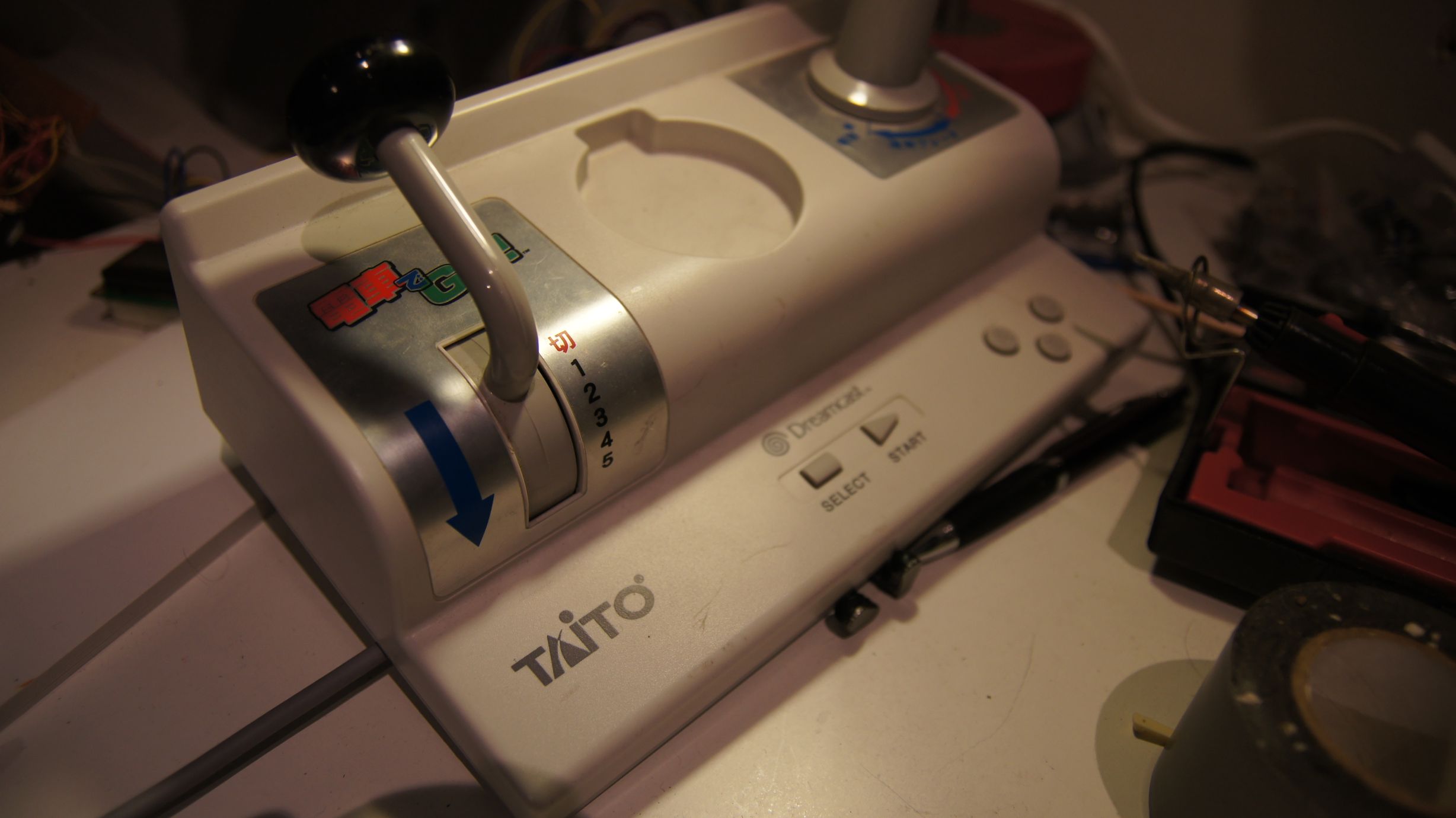
Densha-De-Go controller workings
So, after having used the standard Dreamcast controller to play hours-upon-hours of Shenmue, Shenmue II and Chu chu rocket, I would have expected at least one of the levers on the Densha-De-Go controller to use the analog joystick and the other to also use some form of analog control. After a few minutes decoding the controls, it became apparent that they simply used the buttons available (up, down, left, right, x, y, z) in a binary-value style configuration.
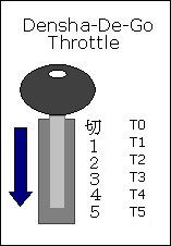
| Throttle Position | X | Y | Z |
|---|---|---|---|
| T0 | [x] | [x] | |
| T1 | [x] | [x] | |
| T2 | [x] | ||
| T3 | [x] | [x] | |
| T4 | [x] | ||
| T5 | [x] |
| Other Buttons | Mapping |
|---|---|
| SELECT | D |
| START | START |
| A | A |
| B | ?? |
| C | C |
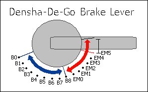
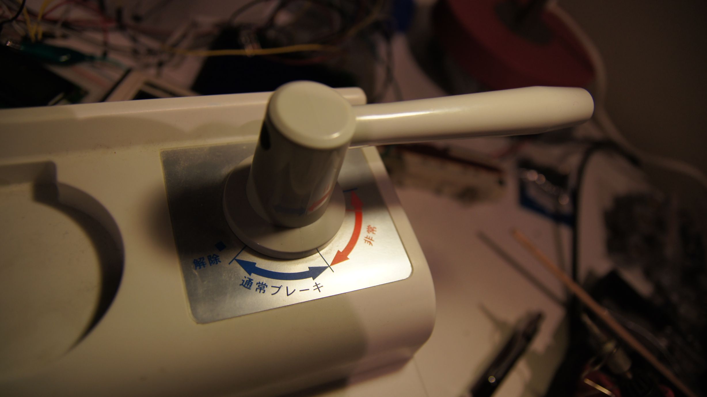
| Brake Position | UP | DOWN | LEFT | RIGHT |
|---|---|---|---|---|
| B0 | [x] | [x] | [x] | |
| B1 | [x] | [x] | [x] | |
| B2 | [x] | [x] | ||
| B3 | [x] | [x] | [x] | |
| B4 | [x] | [x] | ||
| B5 | [x] | [x] | ||
| B6 | [x] | |||
| B7 | [x] | [x] | [x] | |
| B8 | [x] | [x] | ||
| EM0 | [x] | [x] | ||
| EM1 | [x] | |||
| EM2 | [x] | [x] | ||
| EM3 | [x] | |||
| EM4 | [x] | |||
| EM5 | - | - | - | - |
In between the B's there is a slight overlap of the buttons, where the current and next 'combination' is combined, but this doesn't seem to last more than one cycle.
In between the EM's the controller reads UP-DOWN-LEFT-RIGHT. This area exists between all EM's and B8-EM0 and seems to be about 3mm wide.
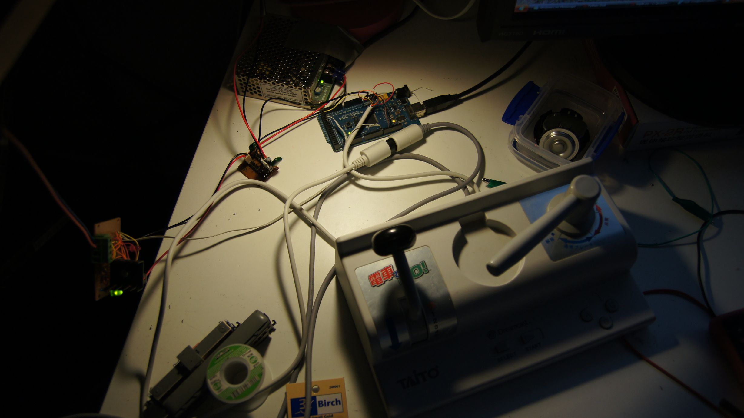
Controlling trains
Now it was time to get this incorporated into my original train throttle. I didn't want to have to use the Python code, so instead I 'crafted' the packets into the Arduino code.
	//here is a quick packet to request device information from controller 'one'.
	//i.e. the only controller connected.
	packet.header[0] = 0; // Number of additional words in frame
	packet.header[1] = 0; // Sender address = Dreamcast
	packet.header[2] = (1 << 5); //(1 << 5); // Recipient address = main peripheral on port 0
	packet.header[3] = 1; // Command = request device information
	packet.data[0]   = 0x21; //checksum
	packet.data_len  = 5;
	//send the above packet to initiate comms with the controller.
	maple_transact();
I'm going to gloss over this part pretty quickly, as this post was more about getting the Dreamcast controller usable rather than another lesson in physics and model railway throttles. For the code, I ended up just deciphering the packet that comes back from the controller, working out what the throttle position is and then adjusting the target speed. The main program loop then makes then increment/decrements the current speed to eventually match the target speed. This provides a very simple form of acceleration.
void control_throttle(void) {
	//quick hack, should actually do a binary 'and'
	//packet data[6] contains the throttle position, so use this to gauge
	//voltage output to pin 7 (or speed)
	switch (packet.data[6]) {
		case 0xF9: target_speed = 0;	t_pos = 0; break;
		case 0xFA: target_speed = 88;	t_pos = 1; break;
		case 0xFB: target_speed = 96;	t_pos = 2; break;
		case 0xFC: target_speed = 140;	t_pos = 3; break;
		case 0xFD: target_speed = 190;	t_pos = 4; break;
		case 0xFE: target_speed = 250;	t_pos = 5; break;
	}
}
The changing of pin 13 below lights the on-board Arduino LED to show once the loop has made the speed match the target speed.
	digitalWrite(13, LOW);
	if (target_speed > speed) {
		//accel
		speed += t_pos / 2;
	} else if (target_speed < speed) {
		//speed += abs(target_speed - speed);
		//decel
		speed--;
	} else {
		digitalWrite(13, HIGH);
	}
	//send the speed to the pin/railway
	analogWrite(7, speed);
And then... it just worked :)
 Download the source code here.
Note that this does not include the Python code; nor will my code correctly interact with the python code anymore. The goal was always to have the Arduino talk to the Dreamcast controller directly.
As you can see, I've only implemented the throttle on the controller... I need to now bring in the brake lever as well, but this is where the physics lesson comes in. I'll be posting again soon enough with source code for acceleration and braking using this controller.
I've got a few ideas as to how to semi-realistically control the train with both levers, but I will need to do a little more reading before I get something going. I do know that in the actual Densha-De-Go game, the game complains when you have both levers on at the same time... and it seems wrong to be doing so... but then again, it'd be like doing a hill-start :) Maybe for freight trains?
If only our model railway trains had gears and could free roll!
Random Photos
Search
Tags
Ads
Links - Click for details
- Abandoned Rails (Japan)
- AIRLINE (Shinkansen Photography)
- Akihabara Station
- annexpressのブログ
- Australian Model Railway Magazine
- DCC普及協会ホームページ (Japanese DCC)
- Dead Section (Japanese Track Diagrams)
- Delicious Things (Japanese N Scale DCC)
- Densha Wotorou
- Digital Direct for Windows (DCC Server)
- Don's Dream World – AMAZING N Scale Japanese Layout
- Hatena::Diary
- Japanese N-Scale Modeling Forum
- JR Chiisai
- Kaz-T's blog レインボーライン (Rainbow Line)
- LED Resitance Calculator
- Masioka
- Poppondetta Blog
- RailFan Magazine, Japan
- Railmind
- Railway Travelers' Room
- Serenity Valley
- Shashinka Ichiban
- Shuzuku
- Sumida Crossing
- The next station is…
- Tomix N Gauge Track and Japanese N Gauge Trains
- TT Forums (Transport Tycoon Deluxe)
- 名鉄尾西線の貨物列車 (Nagoya: Meitetsu Freight)
- 日本型Nゲージ DCC改造例のご紹介 (Okiraku DCC)
- 泰 茅 轍 道 (Taichi Railway)
- 箱庭登山鉄道製作記 (Hakone-Tozan Layout Blog)
Archive
- April 2024
- March 2024
- February 2024
- December 2023
- October 2023
- September 2023
- August 2023
- July 2023
- June 2023
- May 2023
- April 2023
- March 2023
- December 2022
- November 2022
- October 2022
- April 2022
- March 2022
- February 2022
- January 2022
- December 2021
- November 2021
- September 2021
- August 2021
- July 2021
- May 2021
- March 2021
- February 2021
- January 2021
- October 2020
- September 2020
- August 2020
- July 2020
- June 2020
- May 2020
- April 2020
- March 2020
- January 2020
- December 2019
- November 2019
- October 2019
- September 2019
- August 2019
- July 2019
- June 2019
- April 2019
- March 2019
- February 2019
- January 2019
- December 2018
- November 2018
- October 2018
- September 2018
- August 2018
- July 2018
- June 2018
- May 2018
- April 2018
- March 2018
- January 2018
- December 2017
- November 2017
- October 2017
- September 2017
- August 2017
- July 2017
- June 2017
- May 2017
- March 2017
- February 2017
- January 2017
- December 2016
- November 2016
- October 2016
- September 2016
- August 2016
- July 2016
- June 2016
- May 2016
- February 2016
- November 2015
- October 2015
- September 2015
- August 2015
- July 2015
- June 2015
- May 2015
- April 2015
- March 2015
- February 2015
- January 2015
- December 2014
- November 2014
- August 2014
- July 2014
- May 2014
- April 2014
- March 2014
- December 2013
- November 2013
- October 2013
- June 2013
- August 2012
- April 2012
- March 2012
- February 2012
- November 2011
- October 2011
- September 2011
- July 2011
- June 2011
- May 2011
- April 2011
- March 2011
- February 2011
- January 2011
- December 2010
- November 2010
- October 2010
- September 2010
- August 2010
- June 2010
- May 2010
- April 2010
- March 2010
- February 2010
- January 2010
- December 2009
- November 2009
- October 2009
- August 2009
- January 2009
- December 2008
- November 2008
- October 2008
- September 2008
- July 2008
January 17th, 2011 - 10:57
Steve, this is really excellent work! Very exciting. I’ve done a little reading on simulating train physics, and have good links I can share with you later on.
January 17th, 2011 - 11:05
Don, this will come in handy… My only concern is that with boring DC voltage (and very lame PWM) I’ll not be able to adjust the speed to the resolution I really want to.
I also need to work out the timing of the main loop in this version of the code, as the calls the to the Dreamcast are intensive and limit the ability to do other processing in each loop. Of course, I don’t need to poll the Dreamcast each loop, so there is one way to save cycles already.
I’ve already started writing up my basic code for control and will implement it tonight… would then love whatever peer-review you want to suggest :)
Note that my code probably wont even include mutiplication and division :) … When I should really be using exponential curves for acceleration based on current speed vs. throttle position, etc…
More to come soon.
January 19th, 2011 - 10:50
Congratulations on getting it all working — I’m impressed that you managed to get another (very cool looking) controller going, given that the code is somewhat, uh, rough. Sounds like there’s a lot of opportunity to mess around with getting the physics simulation right… could you do different curves for acceleration / braking for different types of train?
January 19th, 2011 - 10:54
The controller was, honestly, such a waste for poor old Sega. It’s only good for one game, and that game was made too late; as the whole Dreamcast was pulled not long after its creation.
But, nonetheless, it works great here. As for the physics… I could definitely do different models per train/locomotive. In fact, it has to be done as each locomotive behaves differently depending on input voltages. Motor sizes and conductivity to the rails mean that one loco at a certain voltage could speed along whereas another hardly moves. It’s all going to get a little tricky… I might try and have an ‘upload’ ability for the train movement models so that don’t have to reprogram each time.
But there’s only so many minutes in an evening :)
And, of course, I can’t thank you enough for getting the initial communications between the controller and the Arduino going!
August 3rd, 2016 - 13:09
Steven,
I’m working on a somewhat similar project; also attempting to use WzDD’s code to communicate with a Dreamcast controller and also using an Arduino Mega (this time with the purpose of flashing custom VMU images). I’ve been able to successfully(?) flash the program to my Arduino using avrdude under Ubuntu, but maple.py seems to consistently time out after 10 echoes of “are you there?”.
I feel like I’m so close I can taste it.. If you still happen to have your modified project files lying about I would really appreciate them!
Thanks,
Hunter
August 3rd, 2016 - 14:51
Hunter,
It’s been forever since I looked at this, so bear with me. Just to confirm, you’ve taken the code from: https://bitbucket.org/nfd/arduino-maple/src and that’s what’s reporting the “are you there?” message?
I’ll download this when I get the chance and try and work out what it’s doing when it’s outputting that line.
Steven.
January 13th, 2019 - 12:02
I would like to get one rip the guts out and hack it to a Ps2 keyboard circuit and driver.
I made a controller by hacking a PS2 keyboard which is the only option to the
pc Windows 7 which MSTS will work in. The home made controller is big bulky
and hokey looking, i had so much problems switch’s, i went through so many
different type of mini switch’s. the switches plastic would melt so i finally had to
find switch’s at Jameco. I used arcade levers for throttle and brake and i took
about 3 months to finally finish the project.
January 14th, 2019 - 08:22
Thomas,
If you’re located in Australia, then use one of these instead of a keyboard controller:
https://www.jaycar.com.au/usb-interface-for-joystick-and-buttons/p/XC9046
Steven.