


 Melbourne BG SCS Train Timetable


Arduino + Thermal Printers (Sparkfun, IBM 4160-TF6)
I've always wanted to print my own receipts... devious activities come to mind; but the following usage of receipt printers is nothing sinister at all. My goal is to print out activities for trains on the layout; certain locations will have a new reporting mechanism!
I'd seen a few printers on eBay, most being USB. Serial was always to be my preferred method and I had the components on hand. I then saw the Thermal Printer at Sparkfun and decided that it'd be my first guinea pig.
Sparkfun Thermal Printer
The Sparkfun themal printer is, like most of their products, targetted at the Arduino. Thanks to this there is a wealth of information on their page on how to connect and use it. After hooking up a proper power supply (they recommend 9v @ 2Amps, so use a 7809 with a heatsink!) the printer just started spewing out whatever I threw at it.
The easiest way to use this is via the library found here: Displaying on Paper – Thermal Printer + Arduino. bildr.org is actually a really cool site full of interesting projects for the Arduino, check it out when you can!
There's a forum for discussing the above library, in which I've already posted my praises to the developer. If you need a hand then go over and ask away... they're always open to feedback and improvements to the library too!
Note that this printer uses small rolls of 58mm paper. I found a 10-pack of these at OfficeWorks (Australia) for AUD$9.95.
IBM 4610-TF6 (on Windows)
I'd finally found a dirt cheap printer on eBay that was RS-232. It was a chunky/retro IBM thermal printer and really was just a larger, more robust version of the Sparkfun thermal printer above. It didn't come with a power supply and, after purchasing, I realised that it wanted 38v! What the hell? It seems that the 'thermal' side of it uses a lot of current to burn the paper! It also wanted 3 AMPS at 38v... where the hell would I find that?
I installed the printer drivers here on a Windows XP 32-Bit machine (DOES NOT WORK WITH 64-Bit!) and provided it 12v @ 2A. The LED came on, but the printer showed up as 'offline'. All attempted connections via Hyper-Terminal showed the port as 'already open'; the printer driver would've been the cause. I uninstalled it and rebooted, but Hyper-Terminal wasn't receiving any responses after connecting successfully.
I then found a second 12v power supply and chained them together... Prior to this I'd re-installed the printer drivers and, upon the boost to 24v, the printer flicked to 'online' and the LED glowed slightly brighter. I could now also use the line-feed button on the top of the printer! I opened notepad, loaded a text file from the Arduino directory and, without thinking, hit print. The printer control panel window showed the job spooling up to 20 pages and then the printer started .... and kept going ... for an hour. It printed at a rate of about 1 line per 5 seconds.
I had no idea how to cancel it... so I had to let it go.
IBM 4610-TF6 (on the Arduino)
It was now time to make this printer talk to my Arduino Mega. I hooked it all up based on how the Sparkfun printer wiring and attempted to use the same code; nothing happened. I then used the code from Tom Taylor's Microprinter blog post. Once uploaded, I had junk coming out of the printer... It occurred to me that I probably needed a MAX232 in the middle to raise the voltages to proper RS232 levels (as per everyone elses examples!)
I hooked up the MAX232 as per the schematic below and then had a functional printer from my Arduino! Determining the actual commands to send it came next.
Fonts, spacing, etc...
Right, this gets tricky... you can either put 58mm or 80mm paper in this printer. 80mm is recommended as it has better chances of staying aligned with the paper cutter (coming out diagonally is actually an issue.) I had started with the 58mm but quickly went and bought 80mm paper (AUD$12 for 4 80x80 rolls) as I also wanted the extra printing space.
You can work out how many characters per line based on the font chosen, character spacing. It is pretty much expected that you're using 80mm paper. Font A is 10x20, Font B is 12x24 and Font C is 8x16. The Cash Receipt print line is 72 mm (2.83 inches) long. There are 576 dots per line and 203 dots per inch.
The Application Guide provides the following calculations:
- 20 CPI ⇒ 8-dot wide character + 2-dot space (Font C) ⇒ 57 characters/line
- 17 CPI ⇒ 10-dot wide character + 2-dot space (Font A) ⇒ 48 characters/line
- 15 CPI ⇒ 10-dot wide character + 3-dot space (Font A) ⇒ 44 characters/line
- 12 CPI ⇒ 12-dot wide character + 5-dot space (Font B) ⇒ 33 characters/line
Printing a Barcode
In a comment below, Jonas has asked how to print a barcode from any programming language via the serial port... Here's a list of instructions to do so:
- Set the Font (0x00 or 0x01):
0x1d 0x66 FONT 0x0a
- Set the Text Location:
- 0x00 - None
- 0x01 - Above
- 0x02 - Below
- 0x03 - Both
0x1d 0x66 POSITION 0x0a
- Set Barcode Width:
0x1d 0x68 WIDTH 0x0a
- Set Barcode Height:
0x1d 0x77 HEIGHT 0x0a
- Print a Barcode. 'CHARS' is the list of characters to print.
- 0x00 - UPC-A
- 0x01 - UPC-E
- 0x02 - JAN13 (EAN)
- 0x03 - JAN8 (EAN)
- 0x04 - CODE 39
- 0x05 - ITF
- 0x06 - CODABAR
- 0x07 - CODE 128 (c)
- 0x08 - CODE 93
- 0x09 - CODE 128 (a, b)
0x1d 0x6b BARCODE_TYPE CHARS 0x00
A 'Hello World' example of point 4 would be:
0x1d 0x6b 0x00 0x48 0x65 0x6C 0x6C 0x6F 0x20 0x57 0x6F 0x72 0x6C 0x64 0x00
IBM SureMark Thermal Printer Library for Arduino 1.0
IBM provides a great reference document for this collection of printers: ![]() Application interface specification for IBM 4610 printers. I found it to be a little hit-and-miss as to what commands are available on the TF6, but most worked well. Either way, I built the following library which provides the following functionality:
Application interface specification for IBM 4610 printers. I found it to be a little hit-and-miss as to what commands are available on the TF6, but most worked well. Either way, I built the following library which provides the following functionality:
- Text Styles: Bold, Underline, Overline, Inverted, Arbitrary Font Scaling, Double Height/Width, Rotated, Upside-down
- Barcode Printing: UPC-A, UPC-E, JAN13 (EAN), JAN8 (EAN), CODE 39, ITF, CODABAR, CODE 128 (c), CODE 93, CODE 128 (a, b)
- Image Printing from data stream, image storing to printer RAM and image printing from printer RAM
- Message storing to printer RAM and printing from printer RAM
- Beeper sounds. (Example below has 'Mary had a little lamb')
- Paper cutting, line spacing, line feeding, etc...
Other references
It turns out that, if I'd google'd more, I would've found a lot more help around the traps... here's a few locations to check out:
Controlling points/turnouts with Servos via the Arduino
I've managed to cook many Tomix Turnouts during my tinkering with the Arduino. The main issue has been applying too much current for too long. The actual switches that come with Tomix points are momentary and, internally, the circuit is only completed very quickly via a spring mechanism. The goal, of course, is to prevent the user from holding the power to the turnout magnet for too long. Unfortunately, I've managed to (via both coding and circuitry mistakes) apply too much power in the past and it takes very little time to melt the roadbase of Tomix Finetrack.
Due to all this, and the desire to use Peco Setrack, I'd decided that instead of Peco Turnout Motors (which also require large amounts of voltage) I'd use the smallest RC servos I could find. Off to eBay I went and the following arrived not so long ago.
I had no idea what servos to purchase: they seem to be rated in grams as to how much they can lift? I read in a few random locations across the web that 9g would be more than enough for switching points.
Hooking up Servos to your Arduino
This could not be easier. Arduino 1.0 already comes with the Servo Library in-built. Simply include this header and then implement the following code. The basic idea is to initialise the Servo on a specific pin (they only require one pin to be controlled) and then hook up the external power source. As per usual, it's not recommended to power too many off the USB 5v.
Mounting Servos to control Turnouts
Got some piano wire? A paperclip? Resistor legs? Any solid piece of wire/metal/rod will work to connect your turnout to a Servo. As you can see below, I've used a .55mm 'hobby wire' to connect everything up as I don't need flexibility and I want it to be robust.
You could also be very tricky and build a full interlocking frame to control multiple points at once. I bought a few 'hinges' (no idea what the real word should be) to allow the rodding to turn corners but thought it easier in the end to just install another Servo :).
Rotary Encoders allow you to switch the Turnout yourself...
Rotary Encoders are 'endless' switches which usually come with 5 pins + GND. You can continually turn them, allowing for applications where you want an inifinitely adjustable value. The pins are as follows: one side has two pins which are for the 'pushbutton', as the actual stem can be pushed into the base and provides a momentary switch. The other three on the other side are for the rotor location. The inside pin is 'common' and needs to go to ground; the outside pins are 'data' and need to be hooked into digital inputs somewhere on your Arduino.
You then simply download the rotary encoder library from PJRC, drop the main Encoder.cpp and 'utils' folder into your sketch folder and include the following source lines.
#define ENCODER_DO_NOT_USE_INTERRUPTS

#include "Encoder.h"
#include <Servo.h>

Encoder myEnc(7, 8);

Servo myservo;
long position = -999;
long srv = 0;
void setup() {
  myservo.attach(5);
}

void loop() {
  long newPos = myEnc.read();
  if (newPos != position) {
    if (newPos < position) {
      srv += 1;
      if (srv > 180) srv = 180;
    } else {
      srv -= 1;
      if (srv < 0) srv = 0;
    }
    position = newPos;
    myservo.write(srv);
  }
}
The code above will check if the rotary encoder has moved and, if it has, then check which direction and adjust the servo accordingly. Note that the servos will hum/jam if you try to turn them past any restrictions: i.e. once hooked to a turnout, the servo's movement will be limited and you should only move them as much as required... don't try and move them past the limits of the turnout. I'm quite sure that you will ruin either the servo or the turnout if you let it hum for too long past the movement of the switch.
What to do next?
Control your points based on timing? Or even based on track occupancy detection. Computerised turnout control will allow you to automate any movement over your layout. Of course, my current goal is to build a node for the OpenLCB project to control points via servos. This will need to store data, allow max/min settings per point, etc... but more as it gets built!
Persistent Data on the Arduino (EEPROM)
It's taken me a year to realise that you can actually store data at runtime on the Arduino and happily turn it off, expecting the data to still be there when you turn it on. By this, I don't mean the code you've uploaded; I mean the actual values you've created/calculated/determined whilst your code has been executing on the Arduino.
Actually, I lie... it hasn't taken a year to 'realise'... it's taken a year to actually need the ability to store information. It occurred to me, whilst looking at Don's OpenLCB railstars products, that they'd need to store everything they 'learn' as you set them up with controller nodes. All of my previous projects would've forgotten all settings once you disconnect the power!
Memory Types on the Arduino
After a little research, it turns out that Arduinos have three types of memory areas. These would be the flash, EEPROM and SRAM. The former is the location that all 'sketches' and other compiled program code go, therefore being the largest area. The EEPROM is, depending on your chip, an area around 1k to 4k in size for storing data to be persisted. Finally the SRAM is the 'running' area where data is stored during runtime of your code.
| Memory Type | ATMega168 | ATMega328P | ATmega1280 | ATmega2560 |
|---|---|---|---|---|
| Flash | 16k | 32k | 128k | 256k |
| SRAM | 1k | 2k | 8k | 8k |
| EEPROM | 512 bytes | 1k | 4k | 4k |
So, as you can see, the more you pay for the microprocessor, the more space you get to play with. I have used the Arduino Mega 1280 for a while and had never used the space available in the EEPROM... what a waste. Now I'm tinkering with the Atmega328P and, as it shows, there's a lot less space available to play with. Fortunately, depending on how frugal you are with data storage, there's more than enough for creating our OpenLCB nodes.
Working with the EEPROM
Arduino 1.0 (and all previous versions) include the EEPROM Library. This library includes two calls, being read() and write(). For the Atmega328P, I'm able to store a byte in 1024 areas. This expands to 4096 areas for the Mega.
By the way, for time-critical apps, an EEPROM write takes 3.3 ms to complete.
NOTE: As the Arduino page warns, EEPROMs are only good for 100000 writes! Please only write/update your EEPROM areas sparingly and when absolutely required.
Efficient storage of Bits/Bytes
Depending on your requirements, you may want to be more efficient in the way you store certain values. We'll start with booleans: if you're lazy and wont need to store over 1024 booleans on an Atmega328p then you can simply check the boolean and store a '1' or '0' in any of the 1024 areas. Of course, if you need more, then you'd want to efficiently use the 8 bits per byte that you have available. As each of those 8 bits can be a '1' or a '0', you can then actually store 8 booleans in each byte. It's simply a matter of 'or'ing 8 booleans together and left-shifting to ensure you set the correct bit.
byte setBit(store, bit) { //bit 1 is right-most
      store |= (1 << (bit - 1)); //set bit 5 to '1'.
}

byte clearBit(store, bit) {
      store &= !(1 << (bit - 1));
}

bool getBit(store, bit) {
      byte b = (1 << (bit - 1));
      return (store & b);
}
Arduino has a good bit of information on BitMasks and BitMath for those interested.
Using PROGMEM to store 'known' data
So, as previously mentioned, the Flash area has the most space available. The Arduino comes with the PROGMEM library for storing variables in this area. Note that you cannot easily write to this at run-time (I haven't dug far enough to work out if you really can) ... the goal is to just store large data in the flash and use it from there at runtime rather than copying to your limited SRAM first.
Firstly, you need to select from a datatype below:
| Data Type | Description |
|---|---|
| prog_char | a signed char (1 byte) -127 to 128 |
| prog_uchar | an unsigned char (1 byte) 0 to 255 |
| prog_int16_t | a signed int (2 bytes) -32,767 to 32,768 |
| prog_uint16_t | an unsigned int (2 bytes) 0 to 65,535 |
| prog_int32_t | a signed long (4 bytes) -2,147,483,648 to * 2,147,483,647. |
| prog_uint32_t | an unsigned long (4 bytes) 0 to 4,294,967,295 |
Now, declare it in the PROGMEM 'space'. It seems that the Arduino devs recommended it to be stored as an array as you'd usually only use this space for large amount of data.
I've chosen the prog_uint16_t (note that this var size is a 'word'), the code below stores two of these values and then uses them during execution.
#includePROGMEM prog_uint16_t myValues[] = { 123, 456 }; int k; //counter? don't quite know what for. int readValue1, readValue2; void setup() { k = 0; //read the first word. readValue1 = pgm_read_word_near(charSet + k); k = 1; readValue2 = pgm_read_word_near(charSet + k); } void loop() { //now you should probably do something with these values... }
And that's it.. I hope this helps some of you to limit your SRAM requirements and also to store data for users each time your device is switched off!
Building an Arduino from scratch
OK, OpenLCB is the new cool... to make 'nodes' for it, we need a skeleton Arduino to build from. This article will define how to go about this. The goal in the end is to have a prototype that can, via the Arduino IDE, have a sketch uploaded to do as you wish.
References
Firstly, a list of random links for random information on building your own Arduino:
- Arduino has a page on this: Standalone Assembly. Note that the diagram is WRONG and this schematic is not recommended.
- TheTransistor has their Minimalist Arduino Article which is perfect. This uses USB.
- Praveendb’s Weblog has a post titled Interface the Atmega 16/32 with the PC which shows how to connect the Atmega via a MAX232 Serial (NOT USB)
- There's a post at NKC Electronics Tutorials detailing how to assemble a 'Freeduino' V2.0 [MAX232] and then the 'Freeduino' v1.0 [Basic Serial Interface].
Serial or USB?
I know the DB-9 Serial Port is archaic... needs an Interrupt Request (IRQ) assigned to it etc, etc... but there's something nostalgic about plugging in a chunky cable instead of a new USB-B connector. It's also cheaper and easier to use parts on hand and I had a few MAX232s sitting around.
To use USB you'll need an FTDI chip to convert the USB signal from your PC to the TTL protocol of which the Arduino understands. Note that there are also FTDI chips which convert USB to RS232, the serial protocol that allows devices (specifically your old dial-up modems) to communicate over serial cables. You don't want one of these as you'd then have to convert the RS232 again to TTL.
Which Microcontroller?
Good question! Your choice of microcontroller comes down to size and quantity of digital/analogue inputs and outputs. I decided on the Atmega328P as it has enough IO lines for what I need on each OpenLCB node; I'll produce more node types and have them specialise rather than one node that does everything from one board. They're cheap on eBay and they are very similar to the MCU used in the Arduino Duemilanove (5 analogue and ~13 digital IOs.)
Schematic
You'll find schematics all over the web, although none seem to agree on what components are the exact bare-minimum for an Arduino... it actually makes it quite difficult to know exactly what you need. Below is a solid basis to start your Arduino-based invention, containing everything required to program over the serial port.
Building the prototype
There was not much out of the ordinary on the breadboarding of this project. It's actually quite simple and the standard rules of check, check and double-check your wire placement, IC pin numbers, etc... as you go is imperative. The serial cable connection on this project, due to the cable being rigid, can cause issues of dragging the board around. I'd recommend to seat connection and cable first and secure everything to your workbench... You'll then prevent your breadboard from upending when the serial cable chooses to move around.
Programming from the IDE
The MCU chosen is the Atmega328P and, as mentioned, it's closest match is the "Arduino Duemilanove w/ Atmega328". Once everything was connected I attempted to flash using this board, selected in the Arduino GUI, but it didn't work straight away. The initial error was that the chip device ID didn't match. It turns out that the Atmega328 has as a different code to the Atmega328P (something to do with Pico Power.) I had to hack the 'avrdude.conf' file buried in the arduino folder and then it just worked.
Before I knew it I had the servo library in and a mini servo from eBay controlling a Peco point on my layout.
Re-programming an Atmega MCU
I accidentally learnt how to do this... At one point I'd put the MCU in the wrong way around and expected that I'd killed it. The circuit then failed to work after numerous attempts with the TX and/or RX lights constantly lit. It wouldn't accept sketches and I therefore thought the best bet was to re-flash the bootloader + program.
It turns out that my Arduino Mega can be used as an In-Serial Programmer and so I set this up. This can be selected via the "Arduino ISP" option in the "Programmer" menu under the new Arduino 1.0 software.
(Note that the capacitor from +5v to RESET is a 100n non-polarised.)
After the re-flash and a reconfigure of the MAX232 in/outs (the schematic above is the final version that now works perfectly) it all just worked again... for one of the MCUs anyway. The second simply refused to receive sketches; the RX light would not turn off. I took this as a fundamental failure in the chip (I blame my bread-boarding skills) and therefore tried something sneaky: I copied the entire code off the MCU that worked and flashed it to the 'broken' one with avrdude and it's associated avrdude-GUI [direct download link]. It turns out this worked... the chip now did what the previous one did... but in the MAX232 breadboard it still would not accept a new sketch from the Arduino GUI. I attempted to find other methods to 'completely erase/reset' an Atmega, but I couldn't get it to work and so just accepted it's fate of having to copy it's brother.
An attempt to simulate Acceleration and Braking
In my previous post, I'd managed to get my Densha-De-Go Dreamcast controller hooked up to my Arduino Mega. Now although this now meant that I had a great way to control my model railroad, it also meant I had to work out how to code a throttle and a brake lever.
The rules
After a few hours of plotting, I had decided on the following system. It involves a 6-position throttle and an 11-position brake. Each 'position' is to have a 'max speed' and 'speed adjust' associated with it.
Notes
- It is to be assumed that if the brake is on, the throttle is automatically disabled
- MAX is 255 on the PWM Throttle (or max voltage from supply)
- At Throttle 0, the train is neither powering nor braking; we will simply slowly decrement the speed
- There is no feedback to know how fast the train is currently travelling
- There are multiple emergency brake points on the throttle, but we don't care about them.
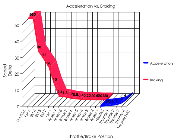
The next table shows my acceleration and braking deltas. This will be a simple addition and subtraction on the current speed.
| Lever position | Max Speed | Speed Adjustment |
|---|---|---|
| Emergency Full | Instant Stop | |
| Emergency 5 | -50 | |
| Emergency 4 | -30 | |
| Emergency 3 | -25 | |
| Emergency 2 | -20 | |
| Emergency 1 | -10 | |
| Brake 9 | -2.4 | |
| Brake 8 | -1.8 | |
| Brake 7 | -1.2 | |
| Brake 6 | -0.8 | |
| Brake 5 | -0.4 | |
| Brake 4 | -0.2 | |
| Brake 3 | -0.1 | |
| Brake 2 | -0.05 | |
| Brake 1 | -0.025 | |
| Throttle 0 | 0 | 0.00 |
| Throttle 1 | 55 | +0.25 |
| Throttle 2 | 75 | +0.5 |
| Throttle 3 | 90 | +1 |
| Throttle 4 | 100 | +1.75 |
| Throttle 5 | 120 | +2.5 |
And now a better way to represent it.
The code
The table above translates to code quite easily... the goal is to have the lever position values coded into an array and then just select the correct entry. Once determined, the main code loop can then determine how to adjust the current voltage output to the rails.
const int throttle_positions = 21;
const int throttle_absolute_maximum_speed = 255;
const int throttle_minimum_speed = 20;
int current_throttle_position = -1; // 0 is EM FULL. Lever must be moved to EM FULL to begin.
float current_speed = 0;
float target_speed = 0;
int throttle_max_speed[throttle_positions] =  {
	0,0,0,0,0,0,0,0,0,0,0,0,0,0,0, //brake positions and Throttle 0
	0, 55, 75, 90, 100, 120
};
float throttle_delta[throttle_positions] = 	{
	0.025, 0.05, 0.1, 0.2, 0.4, 0.8, 1.2, 1.8, 2.4, 10, 20, 25, 30, 50, 9999, //brake
	0.00 /*coast*/, 0.25, 0.5, 1, 1.75, 2.5
};
We then need to determine the current throttle position. We will make it that, at the start of code execution, the train should not move until the throttle has been reset to EM Full and the throttle at '0'.
#define BRAKE_MASK 0xf0
#define BRAKE_SHIFT 4
#define ACCEL_MASK 0x07
void read_throttle_position() {
	int accel = packet.data[6] & ACCEL_MASK;
	int brake = (int)((packet.data[7] & BRAKE_MASK) >> BRAKE_SHIFT);

	if (current_throttle_position == -1) {
		//check that we have EM FULL and Neutral
		if (brake  == 15 && accel  == 1) {
			//set the initial '0' (EM FULL) position.
			current_throttle_position = 0;
			lcd.clear();
		}
	} else {
		if (brake != 1) { //1 == "BRAKE 1", if it's higher, we're braking.
			if (brake > 0) current_throttle_position = brake;
		} else { //BRAKE == 1 and then we check the throttle
			//we're accelerating.
			if ((accel + 15) < 22) current_throttle_position = accel + 15;
		}
	}
}
And now the main game loop needs to determine the current lever locations and then choose the appropriate action:
void update_speed() {
		digitalWrite(13, LOW);
	//make sure we are allowed to go.
	if (current_throttle_position >= 0) {
		if (current_speed > throttle_max_speed[current_throttle_position - 1]) {
			current_speed -= throttle_delta[current_throttle_position - 1];

			//braking... don't go negative.
			if (current_speed < throttle_minimum_speed)
				current_speed = 0;

		} else if (current_speed < throttle_max_speed[current_throttle_position - 1]) {

			//accelerating, so start from minimum speed.
			if (current_speed < throttle_minimum_speed)
				current_speed = throttle_minimum_speed;

			current_speed += throttle_delta[current_throttle_position - 1];

			//don't go faster than current throttle max setting.
			if (current_speed > throttle_max_speed[current_throttle_position - 1])
				current_speed = throttle_max_speed[current_throttle_position - 1];
		}

		//set light if we have met max speed for throttle.
		if (current_speed == throttle_max_speed[current_throttle_position - 1])
			digitalWrite(13, HIGH);

		//output speed to railway.
		analogWrite(7, current_speed);
	} else {
		//flash the LED to alert user to reset controls.
		delay(200); //delay a little to flash the LED
		digitalWrite(13, HIGH);
		delay(200);
	}
}
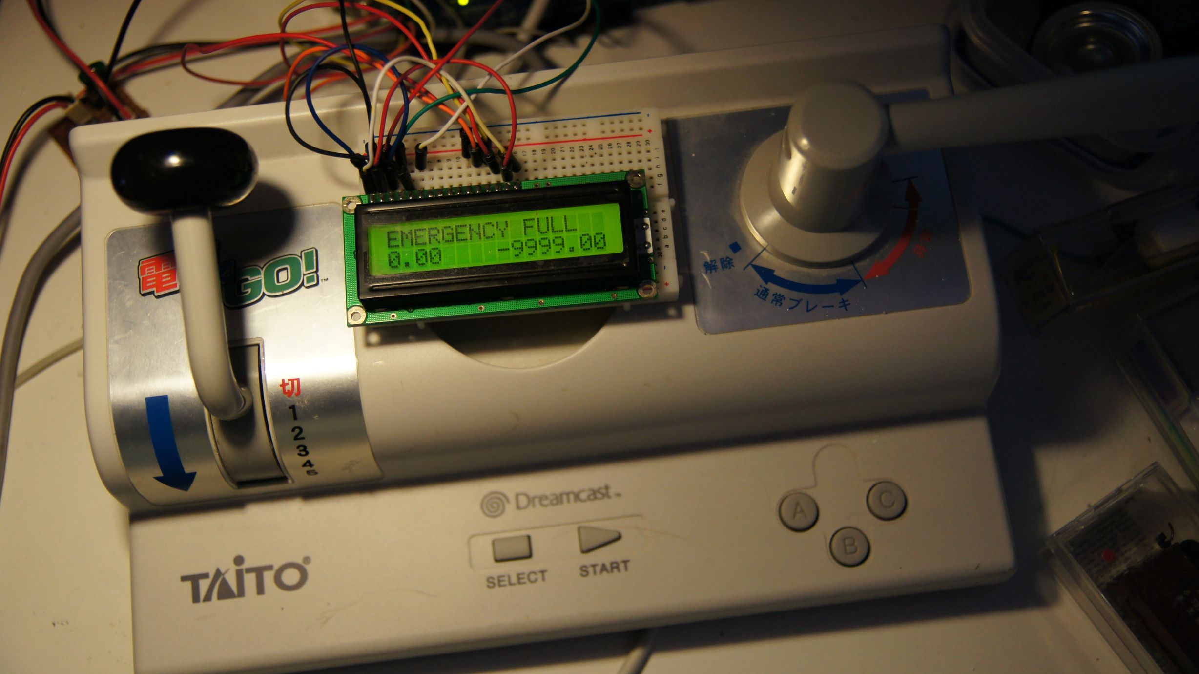
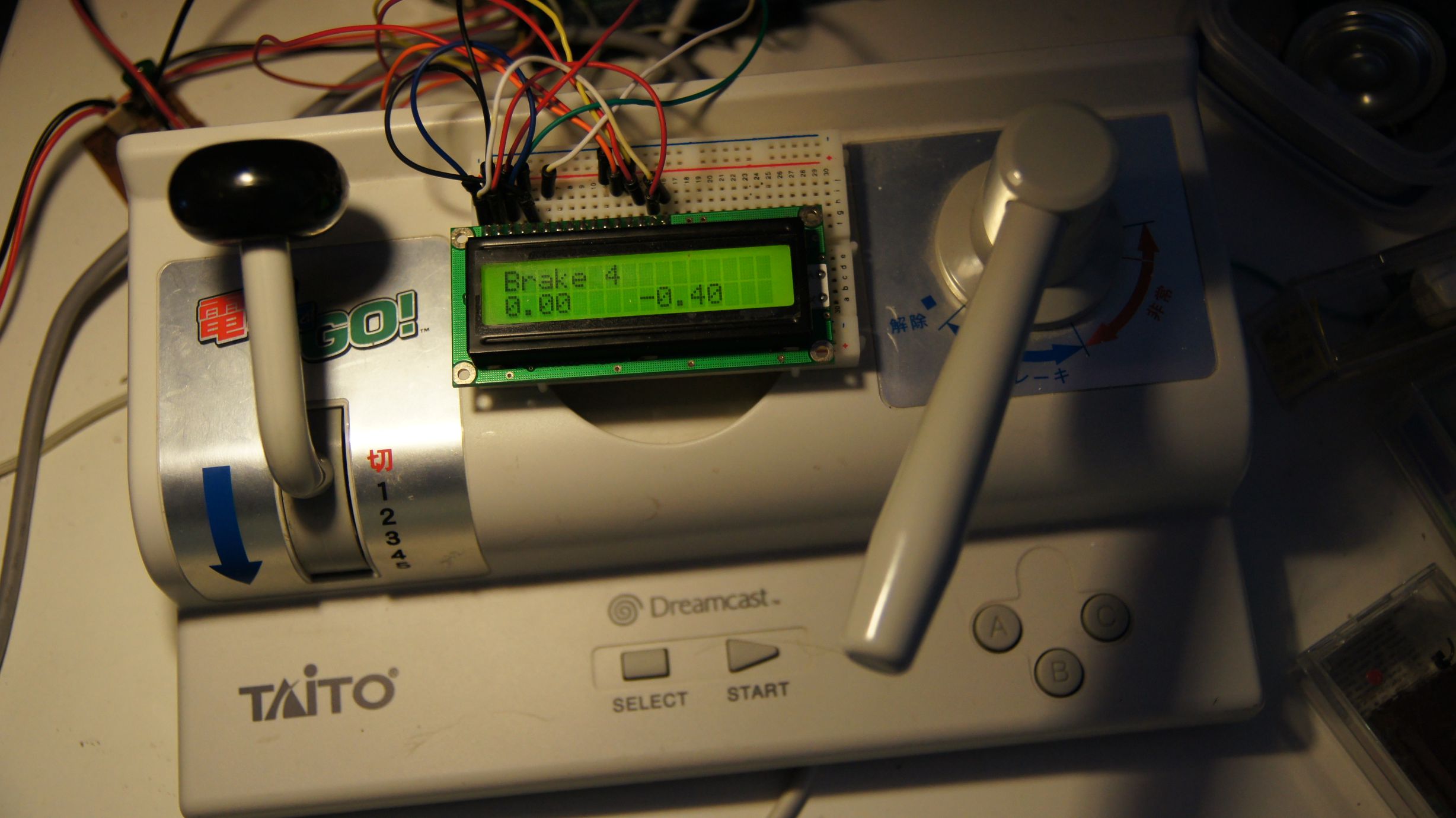
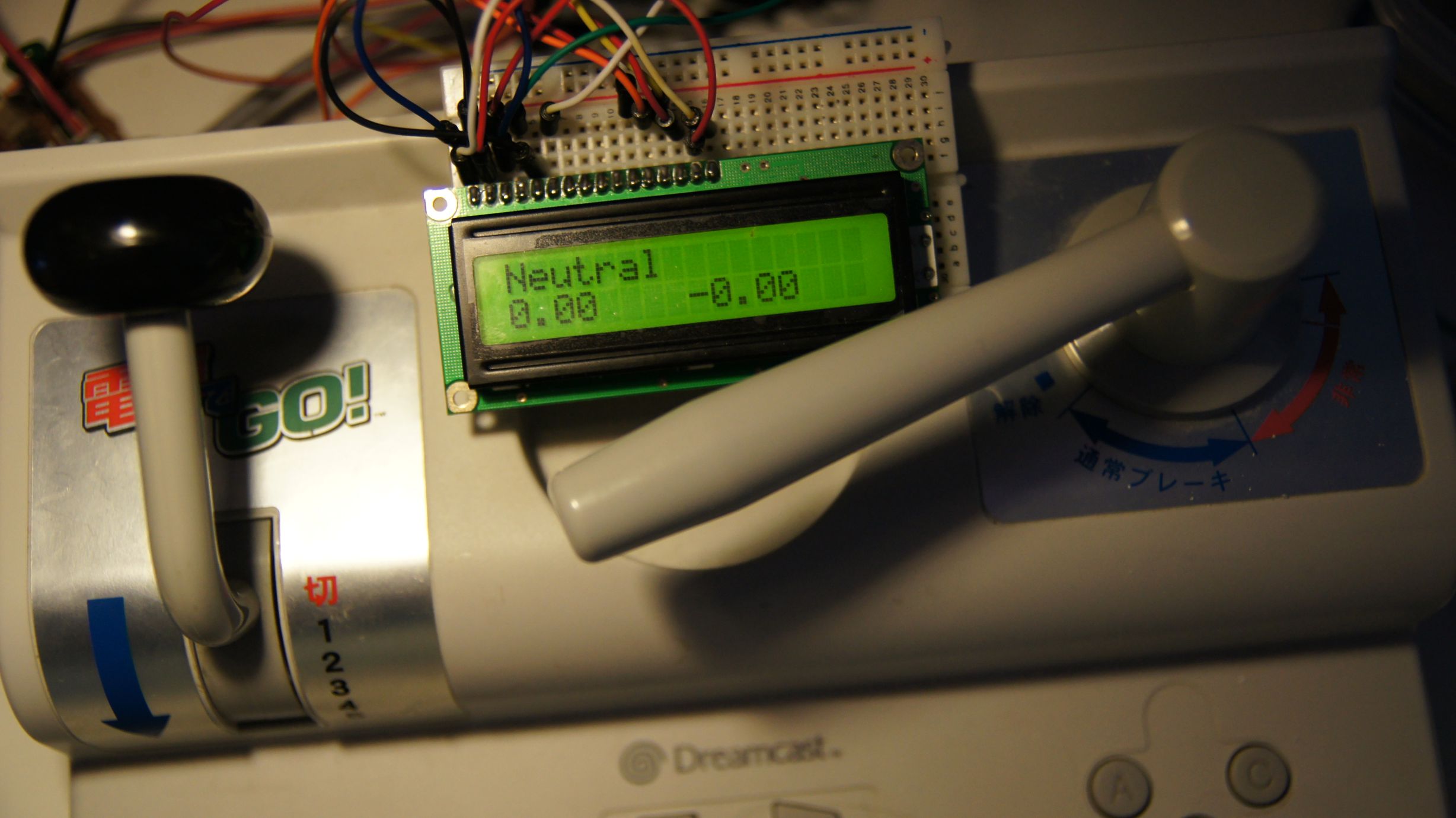
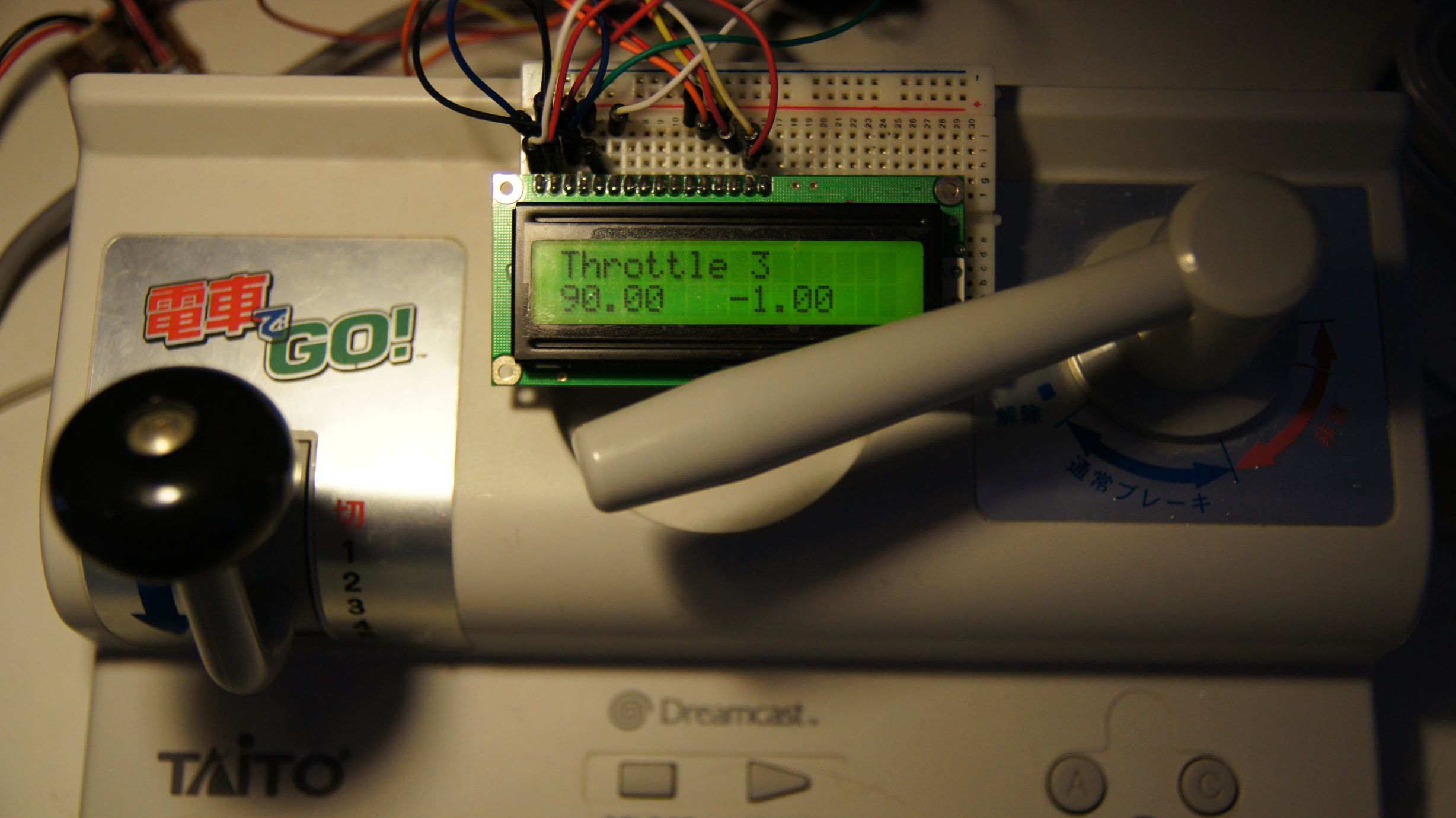
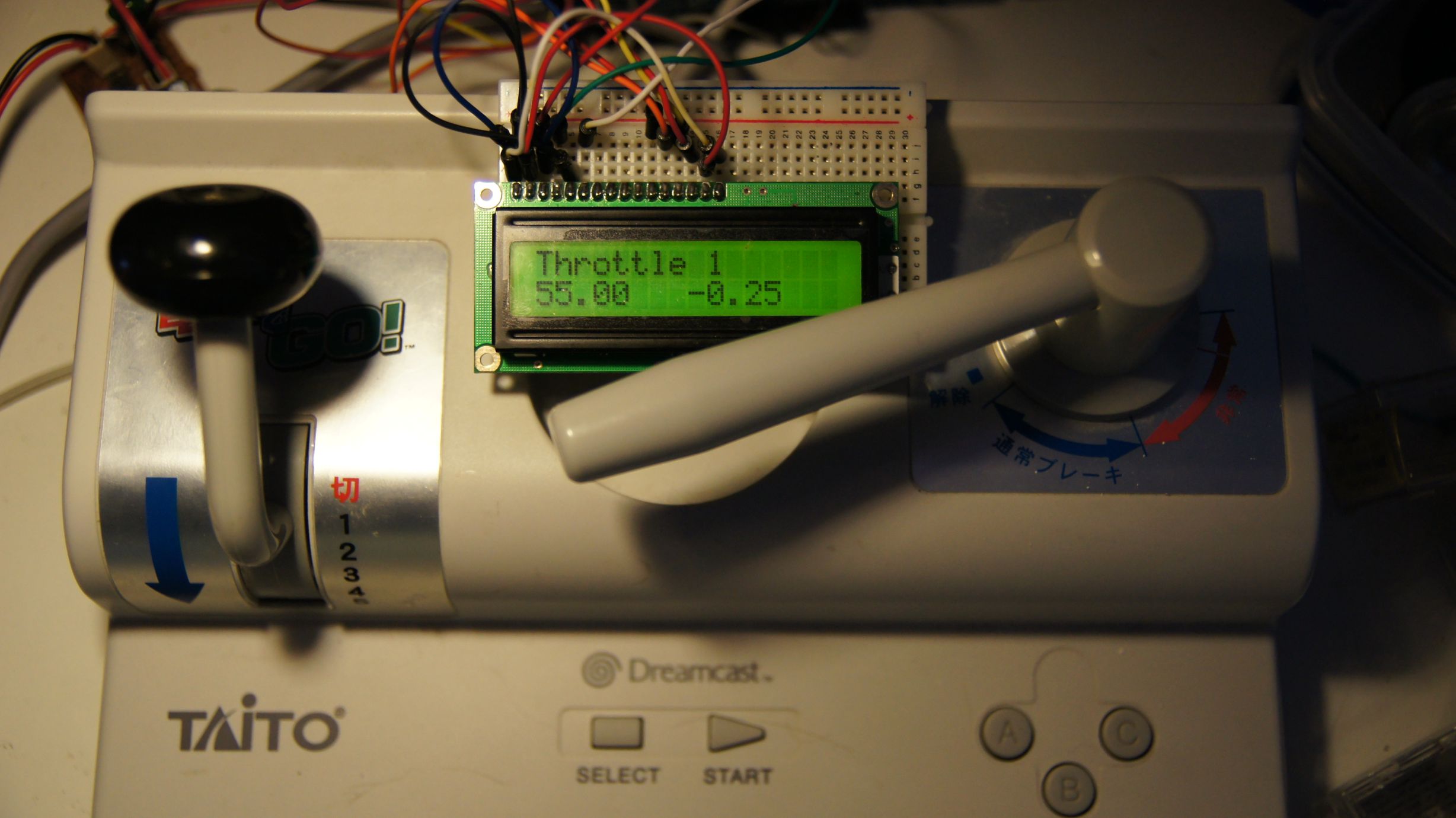
There's also some code in the main loop to update the 16x2 LCD I've hooked up. Since we need to reset the controller when we start, it'll tell you to do so and afterwards will tell you the current throttle/brake position, current speed and speed delta.
 Download the source code here.
Note that this does not include the full arduino-maple code. Download that here. You will also need the LiquidCrystal library from the Arduino site.
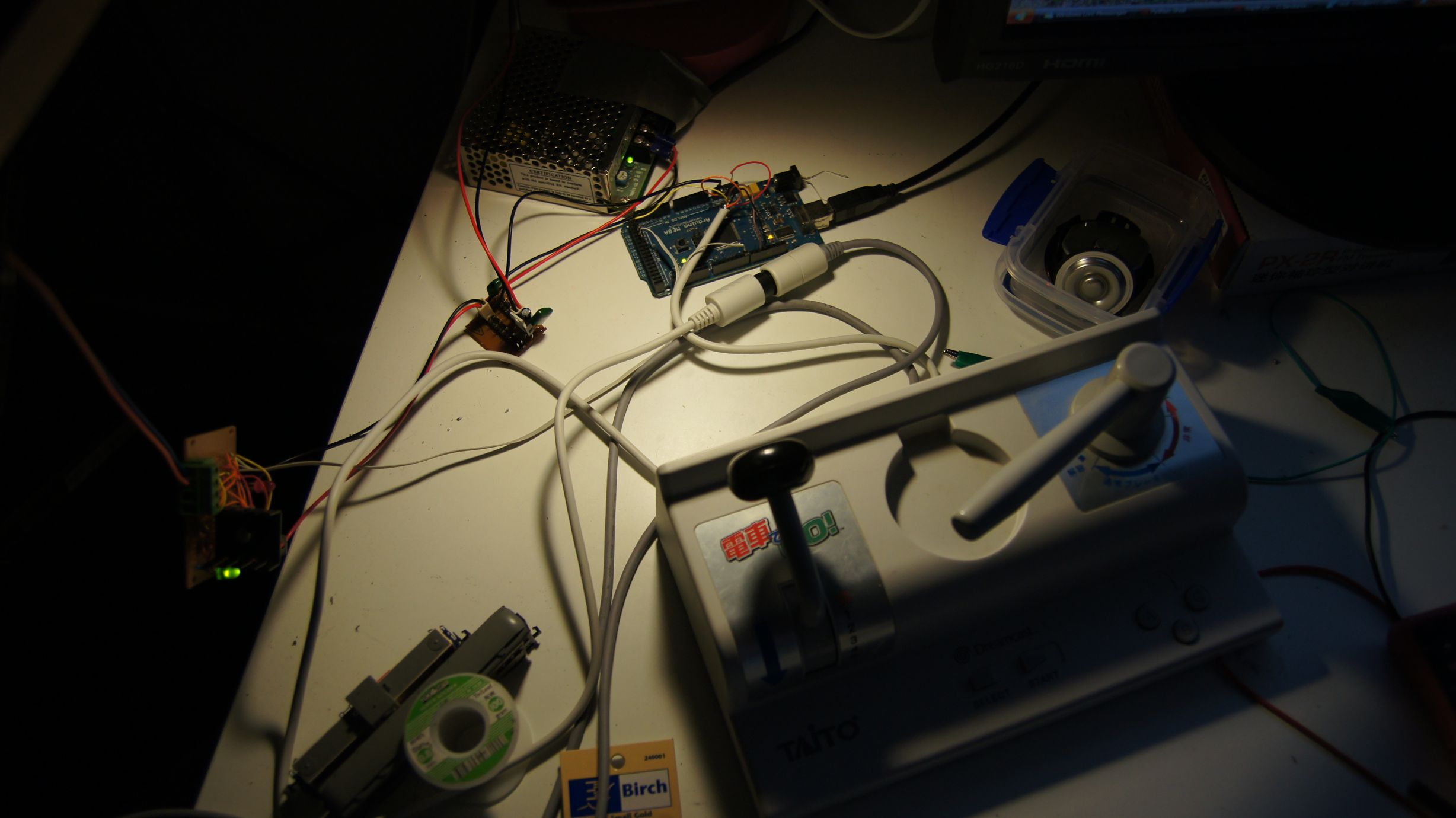
Action shots
Shown is the controller in certain positions. Note that the 'Throttle' positions may show a negative speed delta; this just means that they are no longer accelerating.
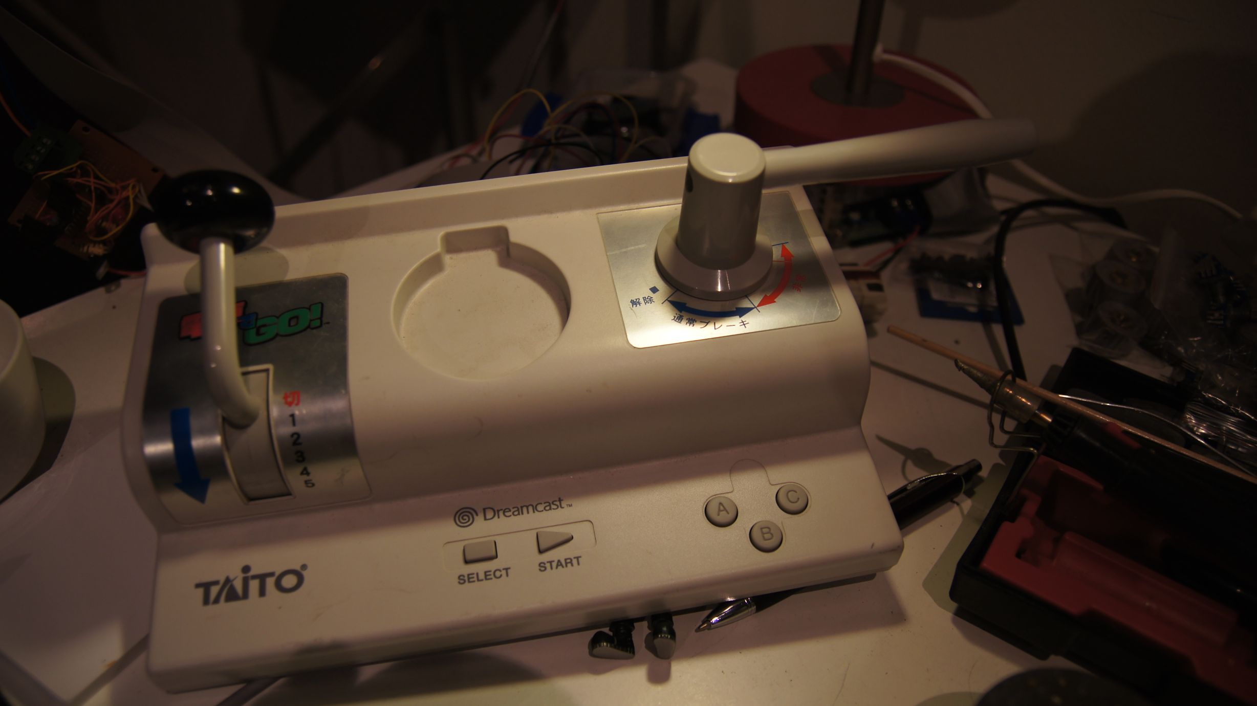
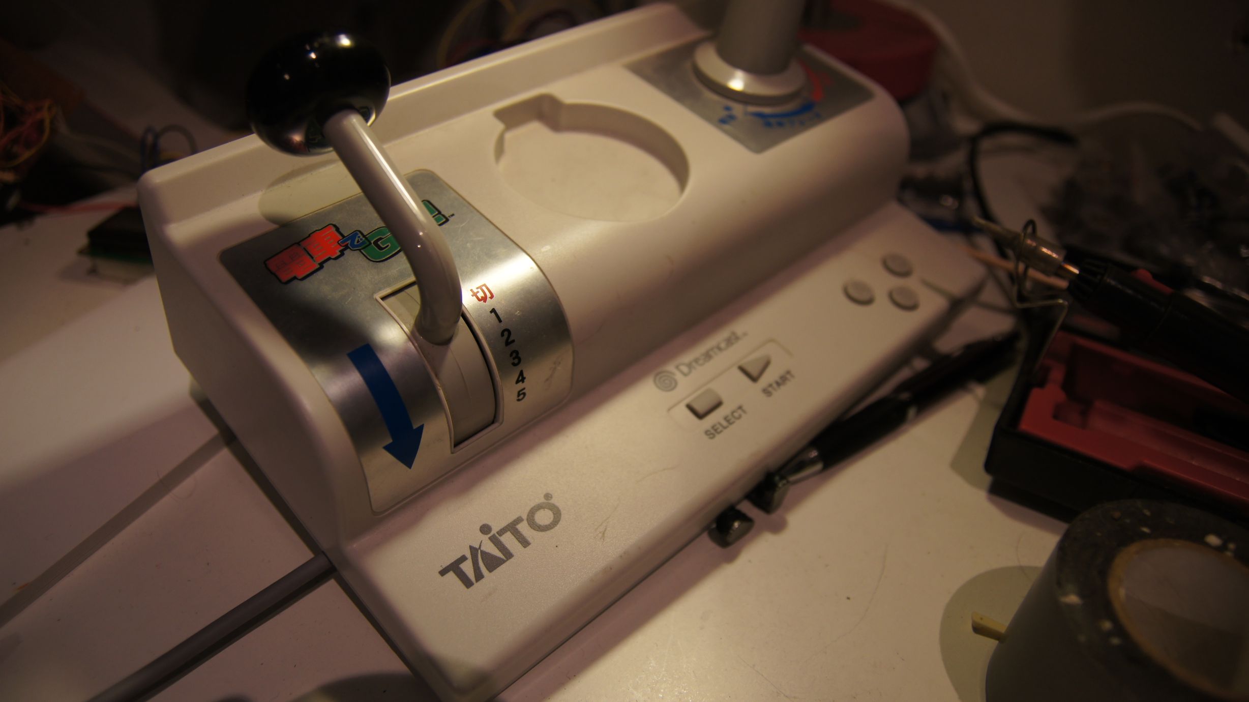
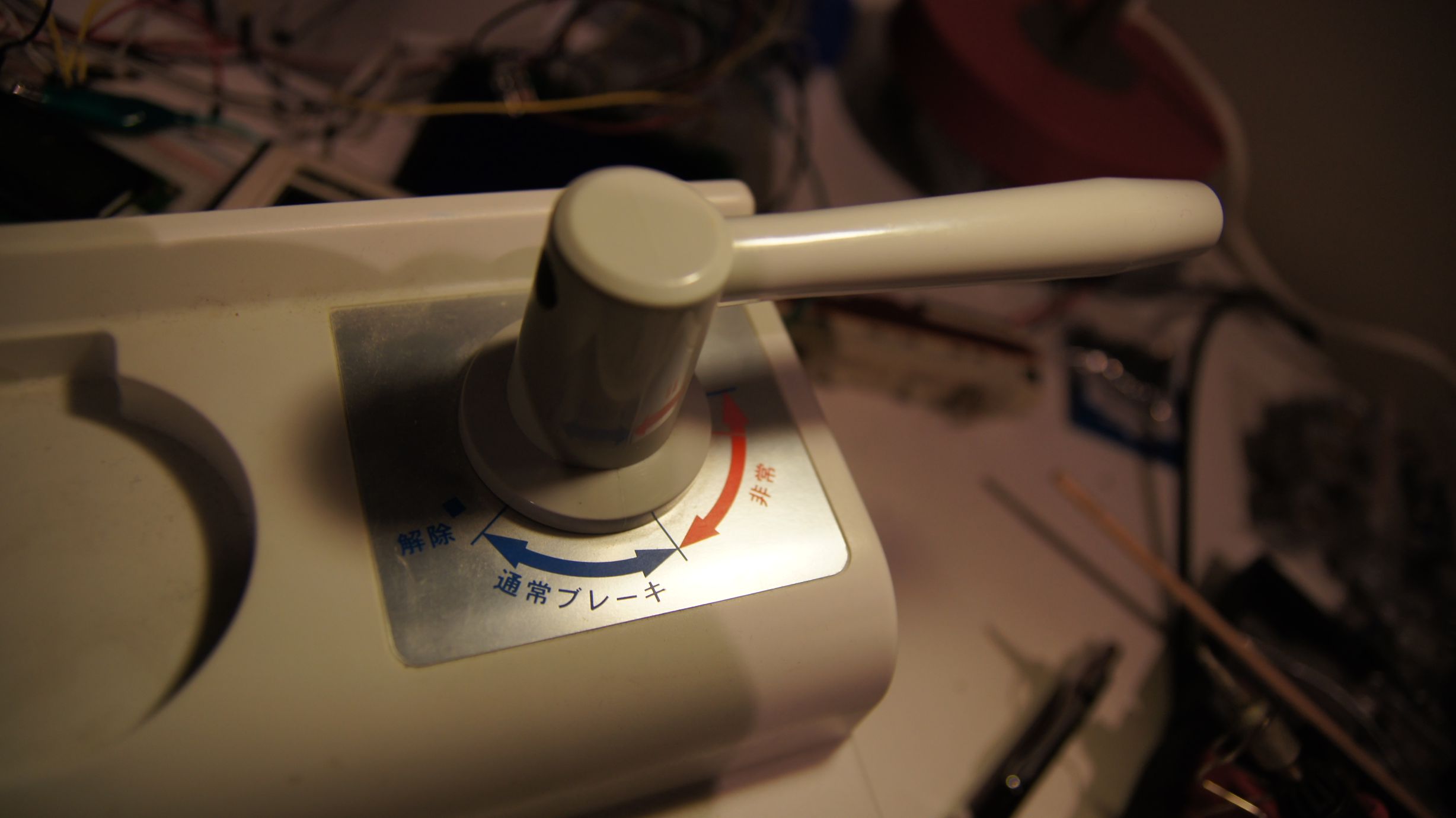
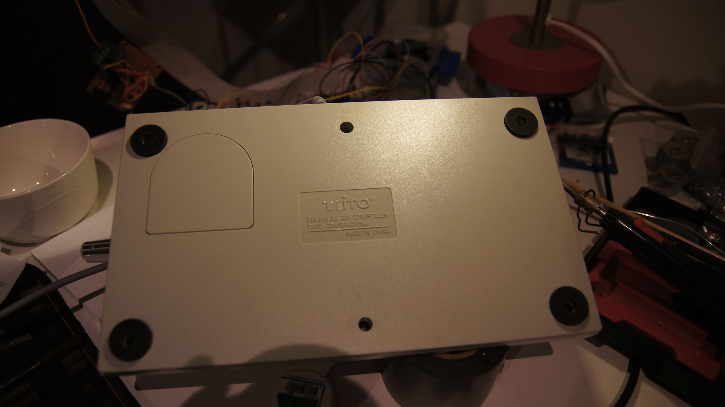
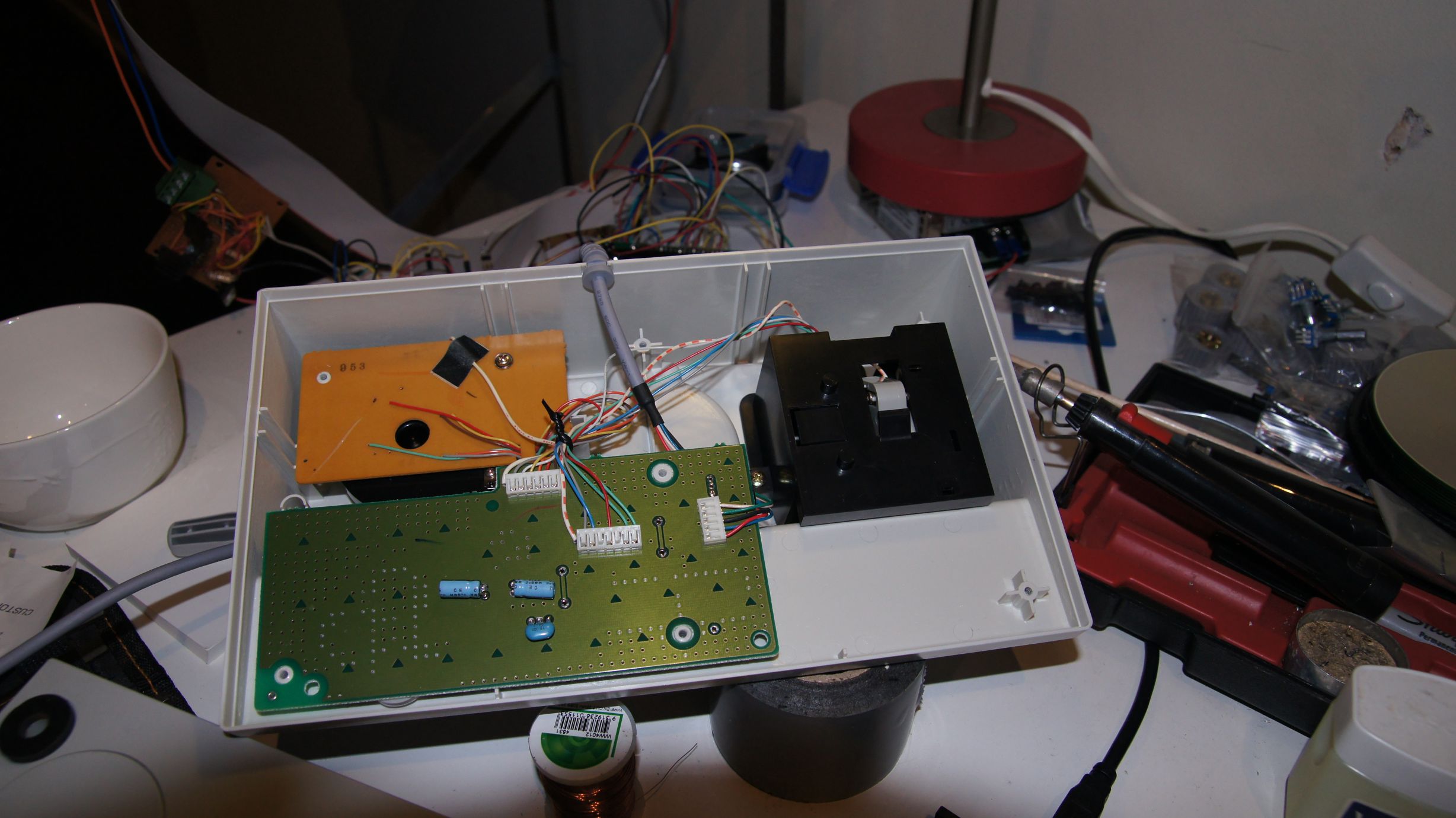
Arduino + Dreamcast Densha-De-Go Controller
I've had Densha-De-Go and the controller for the Dreamcast for a while now... I'd even invested a few hours in playing the actual game, but the accuracy required is crazy. Supposedly in Japan it's that realistic that even real train drivers have a hard time getting it spot on :)
Anyway, I'd wanted to get this going for train control for a while after managing to make a Wii Nunchuck control my trains.
You can find more information on the controller at SEGA Retro, SEGAGAGA Domain, Wikipedia, Play Asia and genki Video Games.
Previous attempts
Quite a few months ago I spent a few hours with my Densha-De-Go controller and my Arduino Mega in an attempt to get them to communicate. The goal was to be able to read the controller and then use it to control my model railroad. Unfortunately, I was doing this blind, running off information from Marcus Comstedt's 'Dreamcast Programming' site; specifically his breakdown of the Maple Bus Protocol.
I ended up with nothing working and sent out a few pleas for help on the Arduino forum and to Marcus himself. I received information regarding the fact that it should work (the Arduino had the horsepower), but I would have to ensure the timing was intricate and that the Arduino was always ready to receive data.
I then posted to the Arduino Forum for help. A few months later WzDD came to my rescue with word that he had successfully made the Arduino communicate with a Dreamcast Controller. I hadn't had much time up until now to work on this, and WzDD hadn't done any further work on it, so I took it that he just wanted to prove the concept and that I'd have to get off my backside to make things progress further. In the end, I did want to get my controller functioning.
I had previously had everything I needed to test this again, so I gave it another go. My previous setup was a cut-in-half Dreamcast controller extension cable and my Densha-De-Go controller. The extension cable meant I didn't have to hack around with the actual controller or port imitation.
Getting set up...
Due to the requirement to use assembler for the actual low-level controller interactions, we cannot use the Arduino IDE and must use WinAVR (or just avrdude on Linux.) Download this from here (select the latest version) and install to the default directory.
You then need to download the arduino-maple source code and extract somewhere locally. I've put the folder on C:\arduino-maple\.
Open Programmers Notepad [WinAVR] from the start menu and then open the arduino-maple.cpp file from where it has been extracted. (C:\arduino-maple\arduino-maple.cpp in my case.)
If all is installed correctly, then you should be able to choose Tools - [WinAVR] Make All and have the following output in the output window:
> "make.exe" all
avr-gcc -Wall -g2 -gstabs -Os -fpack-struct -fshort-enums -ffunction-sections -fdata-sections -ffreestanding -funsigned-char -funsigned-bitfields -mmcu=atmega328p -DF_CPU=16000000UL -I./arduino -c arduino/pins_arduino.c -o build/arduino/pins_arduino.o
In file included from arduino/wiring_private.h:30,
                 from arduino/pins_arduino.c:26:
c:/winavr-20100110/lib/gcc/../../avr/include/avr/delay.h:36:2: warning: #warning "This file has been moved to <util/delay.h>."
...
Lots of warnings, no errors...
...
avr-g++ -Os -Wl,-gc-sections -mmcu=atmega328p  build/arduino/pins_arduino.o build/arduino/WInterrupts.o build/arduino/wiring.o build/arduino/wiring_analog.o build/arduino/wiring_digital.o build/arduino/wiring_pulse.o build/arduino/wiring_shift.o build/./arduino-maple.o build/arduino/HardwareSerial.o build/arduino/Print.o build/arduino/Tone.o build/arduino/WMath.o build/arduino/WString.o build/./libmaple.o -o app.elf
avr-objcopy -R .eeprom -O ihex app.elf  app.hex
avr-size --format=avr --mcu=atmega328p app.elf
AVR Memory Usage
----------------
Device: atmega328p

Program:    3380 bytes (10.3% Full)
(.text + .data + .bootloader)

Data:        796 bytes (38.9% Full)
(.data + .bss + .noinit)

> Process Exit Code: 0
> Time Taken: 00:02
Now, as you can see above... that's not my Arduino! I have an Arduino Mega and therefore we need to adjust the Makefile correctly for my setup. Here you'll need to know the CPU code, interface type and the port number. Also make sure you change the upload task to program so that we can use the menu items in WinAVR.
# Makefile for building small AVR executables, supports C and C++ code
# Author: Kiril Zyapkov
# Hacked up by nfd

SOURCE_DIRS = . arduino
INCLUDE_DIRS = arduino
MMCU = atmega1280
F_CPU = 16000000UL
SRC_ROOT = .
BUILD_DIR = build

CFLAGS = -Wall -g2 -gstabs -Os -fpack-struct -fshort-enums -ffunction-sections \
 -fdata-sections -ffreestanding -funsigned-char -funsigned-bitfields \
 -mmcu=$(MMCU) -DF_CPU=$(F_CPU) $(INCLUDE_DIRS:%=-I$(SRC_ROOT)/%)

CXXFLAGS = -Wall -g2 -gstabs -Os -fpack-struct -fshort-enums -ffunction-sections \
 -fdata-sections -ffreestanding -funsigned-char -funsigned-bitfields \
 -fno-exceptions -mmcu=$(MMCU) -DF_CPU=$(F_CPU) $(INCLUDE_DIRS:%=-I$(SRC_ROOT)/%)

LDFLAGS = -Os -Wl,-gc-sections -mmcu=$(MMCU) #-Wl,--relax

TARGET = $(notdir $(realpath $(SRC_ROOT)))
CC = avr-gcc
CXX = avr-g++
OBJCOPY = avr-objcopy
OBJDUMP = avr-objdump
AR  = avr-ar
SIZE = avr-size

SRC = $(wildcard $(SOURCE_DIRS:%=$(SRC_ROOT)/%/*.c))

CXXSRC = $(wildcard $(SOURCE_DIRS:%=$(SRC_ROOT)/%/*.cpp))

ASMSRC = $(wildcard $(SOURCE_DIRS:%=$(SRC_ROOT)/%/*.S))

OBJ = $(SRC:$(SRC_ROOT)/%.c=$(BUILD_DIR)/%.o) $(CXXSRC:$(SRC_ROOT)/%.cpp=$(BUILD_DIR)/%.o) $(ASMSRC:$(SRC_ROOT)/%.S=$(BUILD_DIR)/%.o)

DEPS = $(OBJ:%.o=%.d)

$(BUILD_DIR)/%.o: $(SRC_ROOT)/%.c
	$(CC) $(CFLAGS) -c $< -o $@

$(BUILD_DIR)/%.o: $(SRC_ROOT)/%.S
	$(CC) $(CFLAGS) -c $< -o $@

$(BUILD_DIR)/%.o: $(SRC_ROOT)/%.cpp
	$(CXX) $(CXXFLAGS) -c $< -o $@

all: app.hex printsize

#$(TARGET).a: $(OBJ)
#	$(AR) rcs $(TARGET).a $?

app.elf: $(OBJ)
	$(CXX) $(LDFLAGS) $(OBJ) -o $@

$(BUILD_DIR)/%.d: $(SRC_ROOT)/%.c
	mkdir -p $(dir $@)
	$(CC) $(CFLAGS) -MM -MF $@ $<

$(BUILD_DIR)/%.d: $(SRC_ROOT)/%.cpp
	mkdir -p $(dir $@)
	$(CXX) $(CXXFLAGS) -MM -MF $@ $<

#$(TARGET).elf: $(TARGET).a
#	$(CXX) $(LDFLAGS) $< -o $@

app.hex: app.elf
	$(OBJCOPY) -R .eeprom -O ihex $<  $@


clean:
	echo $(RM) $(DEPS) $(OBJ) $(TARGET).*

printsize:
	avr-size --format=avr --mcu=$(MMCU) app.elf

# Programming support using avrdude. Settings and variables.
PORT = /dev/tty.usbserial-A700ekGi
#PORT = /dev/ttyUSB0
AVRDUDE_PORT = com3
AVRDUDE_WRITE_FLASH = -U flash:w:app.hex
MCU = atmega1280
AVRDUDE_PROGRAMMER = stk500v1
#AVRDUDE_FLAGS = -V -F -C \app\arduino-0021\hardware\tools\avr\etc\avrdude.conf
AVRDUDE_FLAGS = -V -F \
-p $(MCU) -P $(AVRDUDE_PORT) -c $(AVRDUDE_PROGRAMMER) \
-b $(UPLOAD_RATE)
UPLOAD_RATE = 57600
#
# Program the device.
INSTALL_DIR = \app\arduino-0021
AVRDUDE = avrdude
program: app.hex
	#python pulsedtr.py $(PORT)
	$(AVRDUDE) $(AVRDUDE_FLAGS) $(AVRDUDE_WRITE_FLASH)
The first line in the program target (Line 93) 'pushes' the reset button on the Arduino. As we don't have Python installed we have to do this manually. So, build the source code via the [WinAVR] Make All and ensure there are no errors. Now press the 'reset' button on the Arduino and then quickly choose Tools - [WinAVR] Program. If all goes correctly then you'll see the code uploading to your Arduino:
#python pulsedtr.py /dev/tty.usbserial-A700ekGi
avrdude -V -F -p atmega1280 -P com3 -c stk500v1 -b 57600 -U flash:w:app.hex
avrdude: AVR device initialized and ready to accept instructions

Reading | ################################################## | 100% 0.05s

avrdude: Device signature = 0x1e9703
avrdude: NOTE: FLASH memory has been specified, an erase cycle will be performed
         To disable this feature, specify the -D option.
avrdude: erasing chip
avrdude: reading input file "app.hex"
avrdude: input file app.hex auto detected as Intel Hex
avrdude: writing flash (3508 bytes):

Writing | ################################################## | 100% 1.09s

avrdude: 3508 bytes of flash written
avrdude done.  Thank you.

> Process Exit Code: 0
> Time Taken: 00:03
And that's it, our the compiled code for the arduino-maple project is now on the Arduino and running!
Using the Python code on Windows
I lied, I said I didn't have Python installed... but I ended up installing it anyway. The job to convert the Python code to C# was going to take too long and, to prevent a debugging nightmare, I decided I would get the known-to-work Python code going under Windows first. So, I installed Python from the official website and then started learning :)
Note that I downloaded and installed Python Version 2.6.6 as this was the version that would have been available when arduino-maple was created.
After selecting 'IDLE' from the start menu, I was presented with a light-weight GUI. I opened up the 'maple.py' that's included with the arduino-maple code and attempted to compile it.
I had problems at the start, as in the included Makefile there are two declarations of CPU type. Initially I hadn't set these both correctly and the Arduino includes were not correctly compiled... make sure you carry out a proper clean whenever changing code; this includes manually deleting all of the .o files.
Once this was sorted, it all finally worked... sort of?
connecting to COM3:
connected
SENT: 0000200121
No device found at address:
0x20
SENT: 0000010100
1c20000501000000ff0f3f000000000000000000415400ff204f544920313030746e6f436c6c6f7
2202072652020202020200024191bdc94191958dd481e508815481c9bdc99591b98da5308195
cdb995bdc91881154c8c9b40481051d491551394d25494130b14d1480b911508080808007d00371 117
Command 5 sender 0 recipient 20 length 1c
Device information:
Functions  : CONTROLLER
Periph 1   : 0x3f0fff
Periph 2   : 0x0
Periph 3   : 0x0
Name       : ..TAITO 001 Controller      $.
License    : .....X...P.H..H..Y...S....\....[..T.....Q.I.I%M9M.0A.......P
Power      : 53251
Power max  : 32775
Play with the controller. Hit ctrl-c when done.
SENT: 010020090100000029
SENT: 010020090100000029
1111101010011111
SENT: 010020090100000029
1111101010011111
SENT: 010020090100000029
1111101010011111
SENT: 010020090100000029
1111101010011111
Timing issues
As I continued to run the code, I would get random results as to the 'Name', 'License' and 'Power' fields... well, it was obvious in the text fields that there were problems, but I had no idea that what the 'Power' fields were meant to read. Either way, this indicated a timing issue somewhere and I guessed that life was about to get difficult. Note that I had always been running the controller at 5v, as that's what WzDD's post said the blue wire should be connected to, but it turns out that the device should have actually been running on 3.3v.
Unfortunately, setting the controller on to 3.3v didn't change anything... the responses were still mildly random. The buttons would be sent though correctly (apart from the B button) but the initial device description would come through jumbled. I took a few samples of the data and realised that the data would always have a minimal length. To me this meant that we weren't missing bytes/bits, but actually reading too many. The analysis showed that there were similar chunks all the way through, but at certain intervals there'd be extra/changed characters. Based on Marcus Comstedt's Maple Bus information, I guessed that we were re-reading bits too quickly and needed to slow down a little... This would mean slowing down the pin reading in WzDD's arduino-maple assembler code.
In the maple_rx_raw: function down near _rx_loop:, the code iterates through the pins hoping to read the data. It initially checks the state of the pins to sense when the controller is about to send data, but this did not have the final check for the second pin going low.
4:	IN rport2, _SFR_IO_ADDR(PINB)
	BST rport2, bitmaple5			; maple5
	BRTS 4b							; must be low now
The above code was added around line 305 to ensure this check was in. I then also 'spaced' out the store/read calls by placing a delay in. WzDD had already written the delayquarter macro and I simply re-used this.
	...
	_rx_store rport bitmaple5 5
	_rx_read bitmaple5
	delayquarter
	_rx_store rport bitmaple1 4
	_rx_read bitmaple1
	...
After these two changes, the text from the device information call worked flawlessly. But my B button still didn't work. I decided the B button wasn't important at this stage and went on to decoding the controller to work out how the levers functioned.
Densha-De-Go controller workings
So, after having used the standard Dreamcast controller to play hours-upon-hours of Shenmue, Shenmue II and Chu chu rocket, I would have expected at least one of the levers on the Densha-De-Go controller to use the analog joystick and the other to also use some form of analog control. After a few minutes decoding the controls, it became apparent that they simply used the buttons available (up, down, left, right, x, y, z) in a binary-value style configuration.
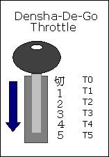
| Throttle Position | X | Y | Z |
|---|---|---|---|
| T0 | [x] | [x] | |
| T1 | [x] | [x] | |
| T2 | [x] | ||
| T3 | [x] | [x] | |
| T4 | [x] | ||
| T5 | [x] |
| Other Buttons | Mapping |
|---|---|
| SELECT | D |
| START | START |
| A | A |
| B | ?? |
| C | C |
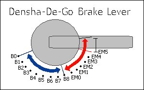
| Brake Position | UP | DOWN | LEFT | RIGHT |
|---|---|---|---|---|
| B0 | [x] | [x] | [x] | |
| B1 | [x] | [x] | [x] | |
| B2 | [x] | [x] | ||
| B3 | [x] | [x] | [x] | |
| B4 | [x] | [x] | ||
| B5 | [x] | [x] | ||
| B6 | [x] | |||
| B7 | [x] | [x] | [x] | |
| B8 | [x] | [x] | ||
| EM0 | [x] | [x] | ||
| EM1 | [x] | |||
| EM2 | [x] | [x] | ||
| EM3 | [x] | |||
| EM4 | [x] | |||
| EM5 | - | - | - | - |
In between the B's there is a slight overlap of the buttons, where the current and next 'combination' is combined, but this doesn't seem to last more than one cycle.
In between the EM's the controller reads UP-DOWN-LEFT-RIGHT. This area exists between all EM's and B8-EM0 and seems to be about 3mm wide.
Controlling trains
Now it was time to get this incorporated into my original train throttle. I didn't want to have to use the Python code, so instead I 'crafted' the packets into the Arduino code.
	//here is a quick packet to request device information from controller 'one'.
	//i.e. the only controller connected.
	packet.header[0] = 0; // Number of additional words in frame
	packet.header[1] = 0; // Sender address = Dreamcast
	packet.header[2] = (1 << 5); //(1 << 5); // Recipient address = main peripheral on port 0
	packet.header[3] = 1; // Command = request device information
	packet.data[0]   = 0x21; //checksum
	packet.data_len  = 5;
	//send the above packet to initiate comms with the controller.
	maple_transact();
I'm going to gloss over this part pretty quickly, as this post was more about getting the Dreamcast controller usable rather than another lesson in physics and model railway throttles. For the code, I ended up just deciphering the packet that comes back from the controller, working out what the throttle position is and then adjusting the target speed. The main program loop then makes then increment/decrements the current speed to eventually match the target speed. This provides a very simple form of acceleration.
void control_throttle(void) {
	//quick hack, should actually do a binary 'and'
	//packet data[6] contains the throttle position, so use this to gauge
	//voltage output to pin 7 (or speed)
	switch (packet.data[6]) {
		case 0xF9: target_speed = 0;	t_pos = 0; break;
		case 0xFA: target_speed = 88;	t_pos = 1; break;
		case 0xFB: target_speed = 96;	t_pos = 2; break;
		case 0xFC: target_speed = 140;	t_pos = 3; break;
		case 0xFD: target_speed = 190;	t_pos = 4; break;
		case 0xFE: target_speed = 250;	t_pos = 5; break;
	}
}
The changing of pin 13 below lights the on-board Arduino LED to show once the loop has made the speed match the target speed.
	digitalWrite(13, LOW);
	if (target_speed > speed) {
		//accel
		speed += t_pos / 2;
	} else if (target_speed < speed) {
		//speed += abs(target_speed - speed);
		//decel
		speed--;
	} else {
		digitalWrite(13, HIGH);
	}
	//send the speed to the pin/railway
	analogWrite(7, speed);
And then... it just worked :)
 Download the source code here.
Note that this does not include the Python code; nor will my code correctly interact with the python code anymore. The goal was always to have the Arduino talk to the Dreamcast controller directly.
As you can see, I've only implemented the throttle on the controller... I need to now bring in the brake lever as well, but this is where the physics lesson comes in. I'll be posting again soon enough with source code for acceleration and braking using this controller.
I've got a few ideas as to how to semi-realistically control the train with both levers, but I will need to do a little more reading before I get something going. I do know that in the actual Densha-De-Go game, the game complains when you have both levers on at the same time... and it seems wrong to be doing so... but then again, it'd be like doing a hill-start :) Maybe for freight trains?
If only our model railway trains had gears and could free roll!
Sending full bytes over .NET Serial Ports to the Arduino
Ok, I have just spent a good two nights of my life diagnosing why I could send all bytes up to value '127' and no higher. In hindsight, it all makes perfect sense and the documentation is clear, but when you've been taught to think in strings, you might hit this very quickly.
The Scenario
I have my MAX7219 + LedControl Library set up on my Arduino and all works fine. I use two functions to control it: setLed and setRow. setLed simply takes a boolean to determine if the LED you are pointing at is to be on or off, but setRow requires a byte. This is all fairly straight-forward as each 'row' in the LED matrix has 8 LEDs, and a byte has 8 bits. So, starting from the lowest significant bit, a value of b00000001 will turn on the first LED in a specified row. (i.e. setRow(DEVICE,ROW,BITS);).
All communications between my application and the Arduino had been based on strings and so I had previously been using one character (one byte) to set one LED. Due to this being a complete waste of bandwidth, I decided that each byte I sent through the channel should be a byte to control full row of LEDs. This meant that I could therefore no longer 'see' the output as a string (or ASCII), as the characters I would create from setting the bits may no longer be in ASCII range... this was no big deal, as I could just view the byte values and decode it all myself.
So, on the client end (C#.NET Application) I started encoding the bytes from bit values. This all worked until I tried to set the last bit...
byte b = 1 | (1 < < 7); //let's set the first and last LED.
string buffer = (char)b + "\0";
serialPort.WriteLine(buffer);
| Data Sent | LEDs lit | Correct? |
|---|---|---|
| b00000001 | 1st | OK |
| b01010101 | 1st, 3rd, 5th, 7th | OK |
| b10101010 | 1st, 2nd, 3rd, 4th, 5th, 6th | WRONG |
| b10000001 | 1st, 2nd, 3rd, 4th, 5th, 6th | WRONG |
| b01000000 | 7th | OK |
| b10000000 | 1st, 2nd, 3rd, 4th, 5th, 6th | WRONG |
What the hell was going on? That 8th bit is fishy!
The Answer
So, after reading numerous blogs and not finding my answer, I went to the Arduino Forums and posted a topic asking for help. I was given advice to write a very simple test app to work out where the bytes were failing... but I never did get to write that app, instead I went to the MSDN site as soon as I saw that the Write() procedure could be overloaded.
And look what I found at the article on MSDN:
By default, SerialPort uses ASCIIEncoding to encode the characters. ASCIIEncoding encodes all characters greater than 127 as (char)63 or '?'. To support additional characters in that range, set Encoding to UTF8Encoding, UTF32Encoding, or UnicodeEncoding.
And guess what... ASCII Character ? is 63 in decimal and therefore b00111111 in binary!
So, whenever I was setting the 8th bit, the .NET Framework (in all its wisdom) would translate this to a question mark as it was not expecting to send an invalid ASCII character. Ladies and Gentlemen, ASCII is only 7 bits!
The work-around?
byte[] b = new byte[] { 1, 127, 128, 129, 255 }; //let's set the first bit, last bit, etc...
serialPort.Write(b, 0, b.Length);
And then everything just worked. Do not send chars to your port if your receiver wants bytes.
Multiplexing ‘Photodetectors’ to detect train occupancy.
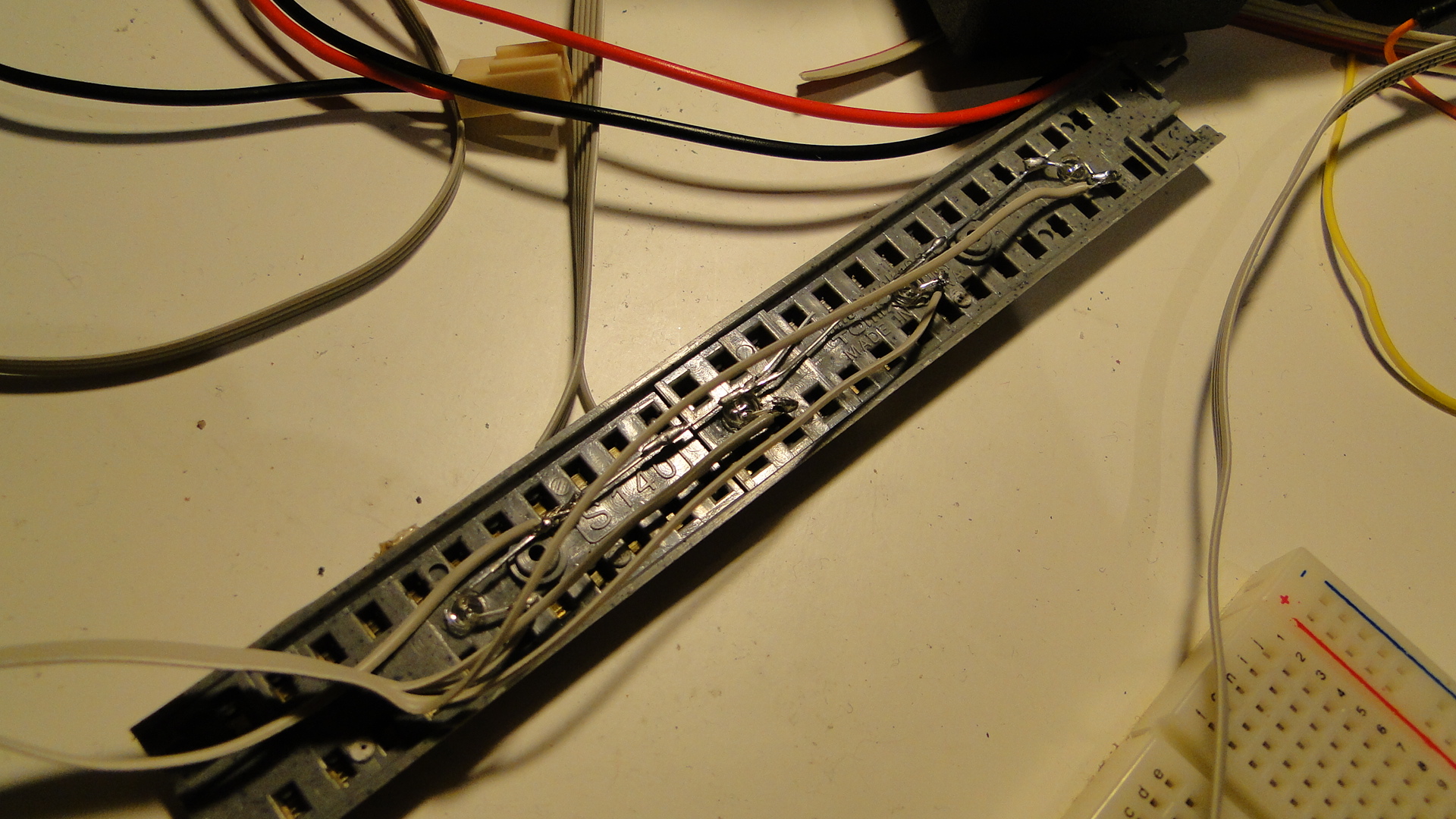
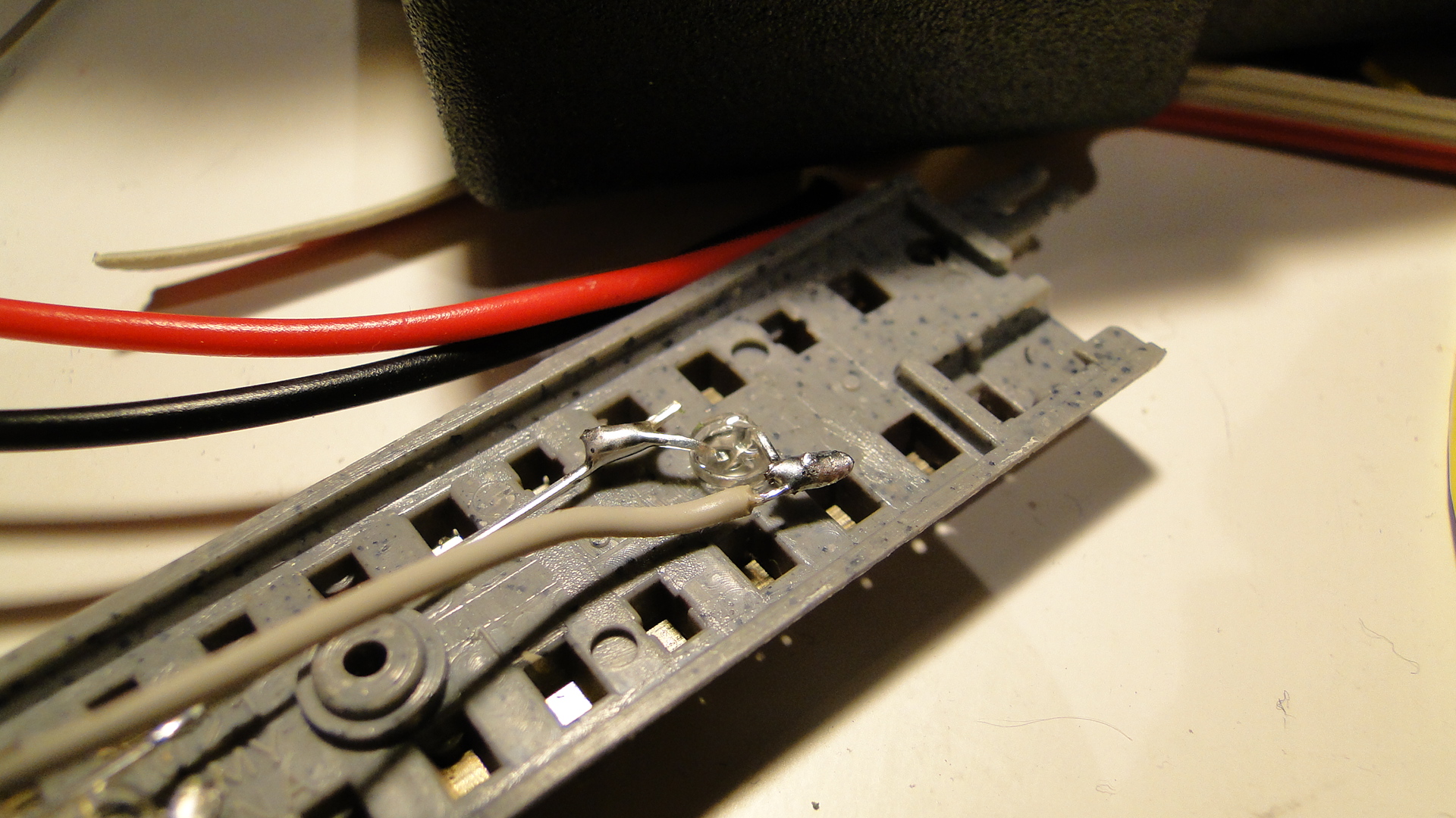
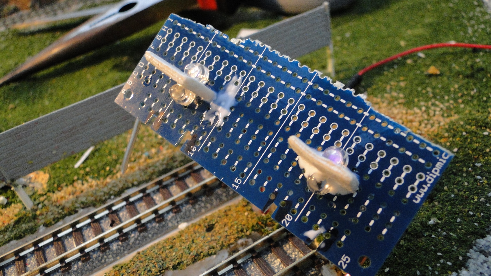
Right, I wasn't impressed whilst using the Sharp distance detectors and so went back to the age-old method of light-detection between the sleepers. As this is N Scale, I didn't want the standard, large and bulky Light Dependent Resistors and went for these smaller 'Photodetectors' found on eBay from a Taiwanese reseller.
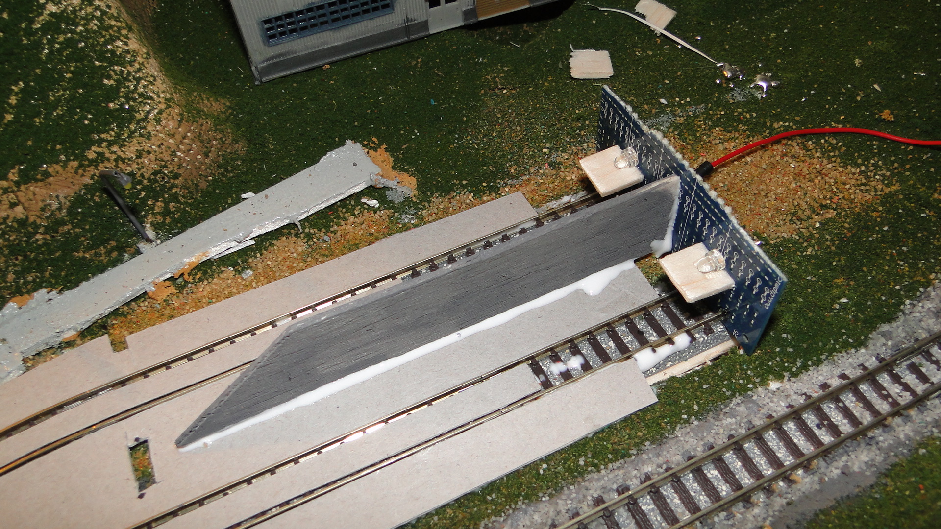
These were chosen based on the fact that they have a flat lens/front and are clear. They fit nicely between sleepers of Tomix FineTrack and, since I'd already laid and ballasted my main loop, could be retrofitted by drilling up and through the base.
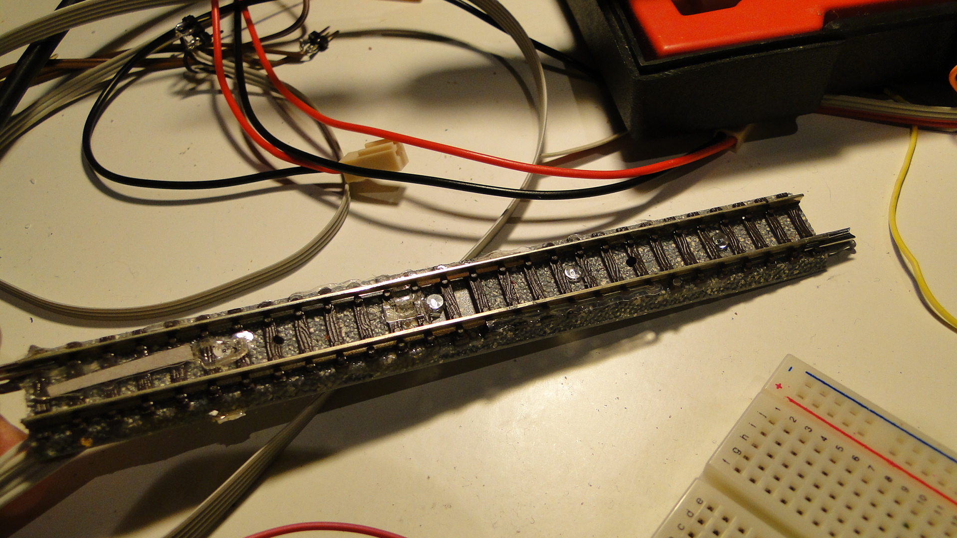
Now, since I bought these in bulk, I started going crazy and sticking them everywhere I could. The goal was to put one everywhere that would become a good trigger-point for automation. I started with all of my stabling areas and put one at the start, middle and end of the sidings. I would use the 'trigger' from these to know when to slow to an engine to 50% throttle, 25% throttle and then stop. I then also put some in the tunnel entrances, station/platforms and also where signals should probably be (around points.)
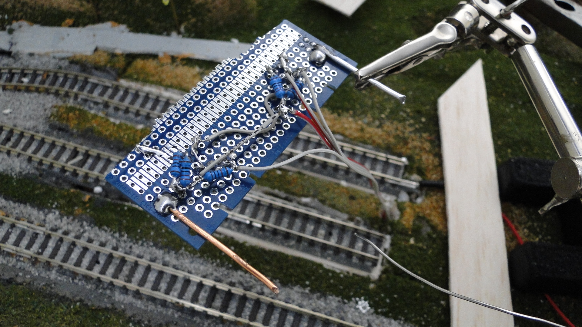
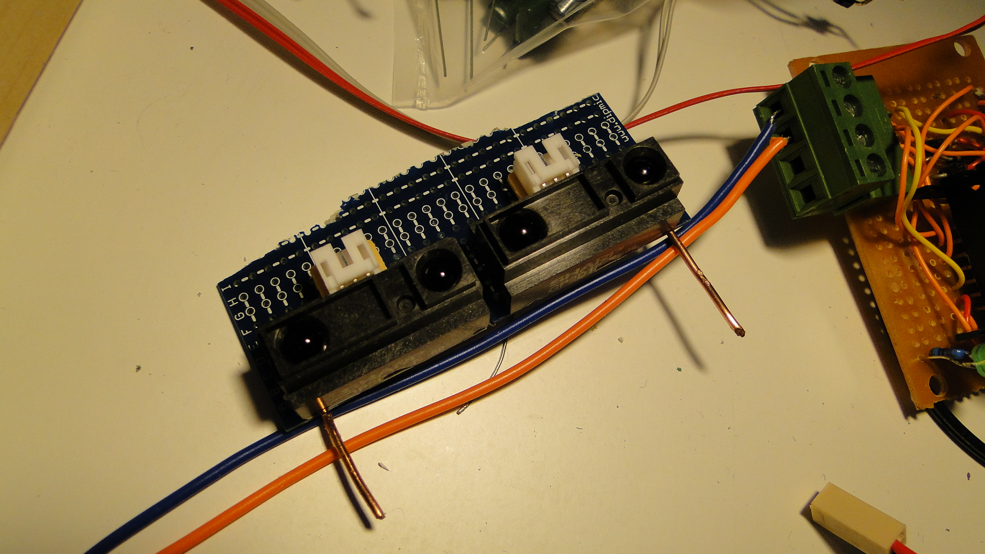
It started dawning on me that I would require one analog input pin on my Arduino per photodetector. This would've gotten very expensive very quickly, but then I remembered that there was a simple tutorial on multiplexing analog inputs on the Arduino Playground (based on the 4051 IC). This IC would save me a lot of time and resources: with a little more wiring it could potentially give me 64 analog inputs for a total of 6 digital pins and one analog.
Here's the basic idea of wiring up a single 4051.
Here's how you can use multiple 4051s and reduce pin consumption:
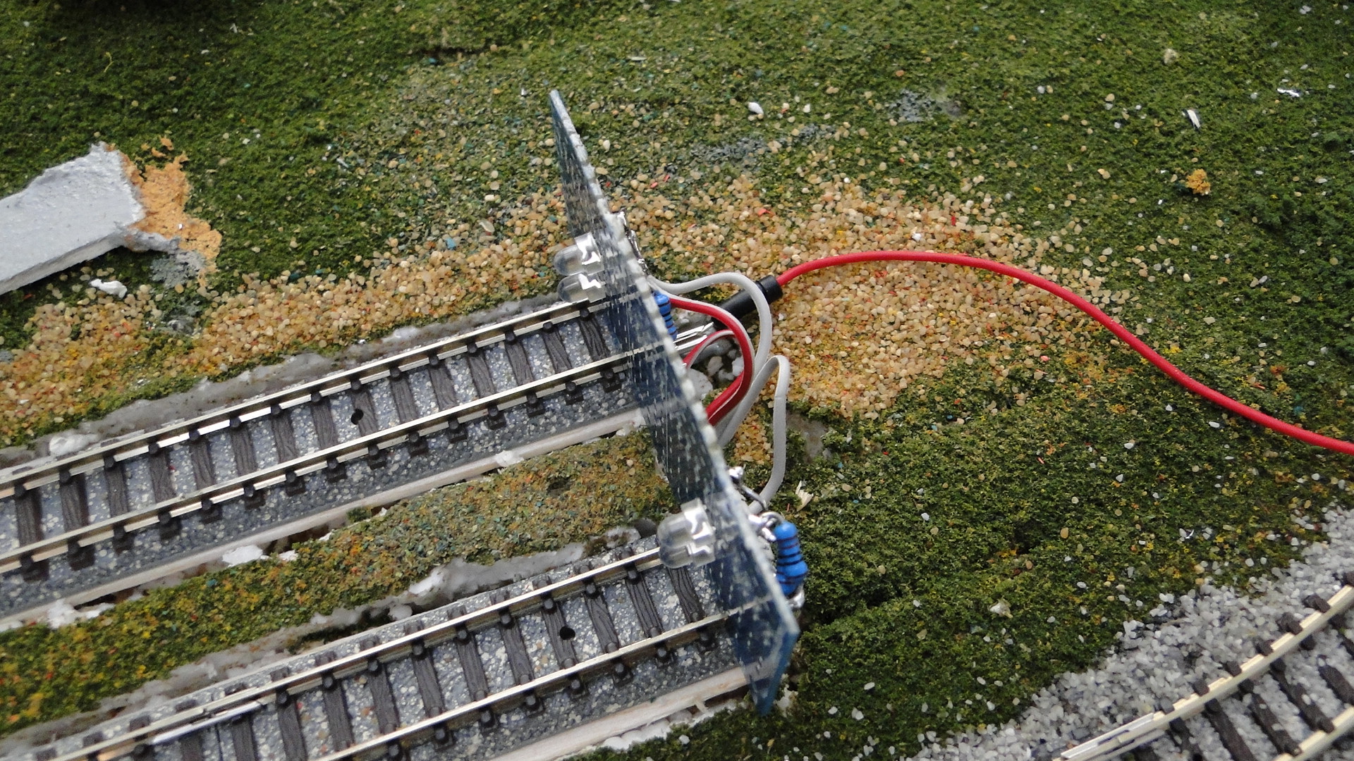
Notes on the options in the above image:
- Option 1: Take the wires in the first rectangle and wire them to one analog pin and three digital. This will give you a total of 8 detector inputs.
- Option 2: Take the 8 analog wires and put them into analog input pins. You then also need to connect up the 3 digital pins. For all inputs you'll only ever need 3 digital pins. But for the analog pins you'll need 1 pin for each 8 inputs. (i.e. 8:1, 16:2, 24:3, 32:4, etc... there is no upper limit, as long as you have the analog inputs.)
- Option 3: Take the single analog pin and then the 6 digital pins. This will give you a total of 64 inputs and will use more digital than analog pins.
As you can see, you can interface with a lot of analog detectors, based on what pins you have available. As you may be aware, analog inputs are more 'expensive' on the Arduino than digital outputs as there are less available.
The process to control the above circuit is to set the digital pins to the desired address and then read the analog pin(s). You then need to set the next address and read the same pin (depending on your setup.) As changing through a lot of inputs and reading can take time, you need to be careful how many detectors you end up implementing. I have no exact numbers; but reading 64 inputs can easily be done in under a second. The goal is to make sure that a train does not pass a detector before it has been read!
So we have our detectors installed and circuitry built; we could now write software to manage it all. The basic idea was to read the value, adjust the min/max of that single detector and then check if it exceeded a threshold. Since these detectors required light to function, they would be effected by the amount of ambient light in the room and therefore the code would need to be smart enough to work out what was 'covered' (i.e. vehicle blocking light) and what was 'open'.
This code was also noted in my previous post where I used the Sharp detectors. These detectors produced a lot of noise and had to be filtered so that my code wouldn't simply trigger when a high/low value broke a threshold.
Here is the basic idea for reading one detector:
 read value of detector
 if (detector value is greater than recorded maximum) then record new maximum value
 if (detector value is lower than recorded minimum) then record new minimum value
 if (either min or max has changed)
  then update range of this detector [max - min]
  adjust threshold [max - (range*0.25)]
 end if
 if (detector value is greater than threshold) then
  report that this detector is 'active'
 else
  report that this detector is 'inactive'
 end if
Right, so the above concept uses a 25% threshold below the maximum-read-value to see if the value read from the detector is 'active'. It is also constantly updating it's valid reading range so that it can adapt to the environmental changes. The main issue with this concept is that if the environment drastically changes (lights are turned on/off, curtains opened/closed, etc...) then this code would not adapt, as it never has a chance to 'retract' the limits. Therefore the following adjustment needs to be made:
 store the last 32 values of detector in circular array
 read value of detector and push last into array, popping off the first value
 find the lowest value in the array and store as the minimum extremity
 find the highest value in the array and store as the maximum extremity
 if (either min or max has changed)
  then update range of this detector [max - min]
  calculate the average from the last 32 read values
  adjust threshold [average + (max-min*0.10)]
 end if
 if (detector value is greater than this threshold) then
  report that this detector is 'active'
 else
  report that this detector is 'inactive'
 end if
Here you can now see that we only care about the last 32 read values (instead of the max and min since the code was running.) We are also using a new threshold calculation: 10% above the average of the last 32 values. This therefore means that we will receive an active notification if the value increases 10% above the 'stable' value of which we have been observing.
Of course, we are always able to introduce new issues; the above code, if run at processor-speed will read 32 values in under a second and, dependent on environment changes, may well not be able to cope. We therefore need to only test the detector at a specific interval (your mileage (kilometre'age) may vary!) of say, 100ms. This then means that the 32 values are taken over the course of 3.2 seconds. If this doesn't suit, then you can also increase the buffer size or decrease the polling delay.
But I bet you haven't seen the main issue? If a vehicle is stationary on the detector for too long then the range will/should drop to zero and therefore the detector will always be 'active'.
Wait, that would be correct? Wouldn't it?
It would, but it would also then report active for a certain time span until the range had expanded again once the vehicle had moved on. Note this can also be simulated by a long train traversing the detector and blocking the light (even with intermittent gaps of light) for a long period of time.
To prevent this? Adjust the polling delay and the buffer size...
Another good trick for limiting environmental effects is to add lights/LEDs to your layout around the detectors to ensure they always have a good source of UV. That way, when those curtains close, the ranges of your detectors wont drop too low.
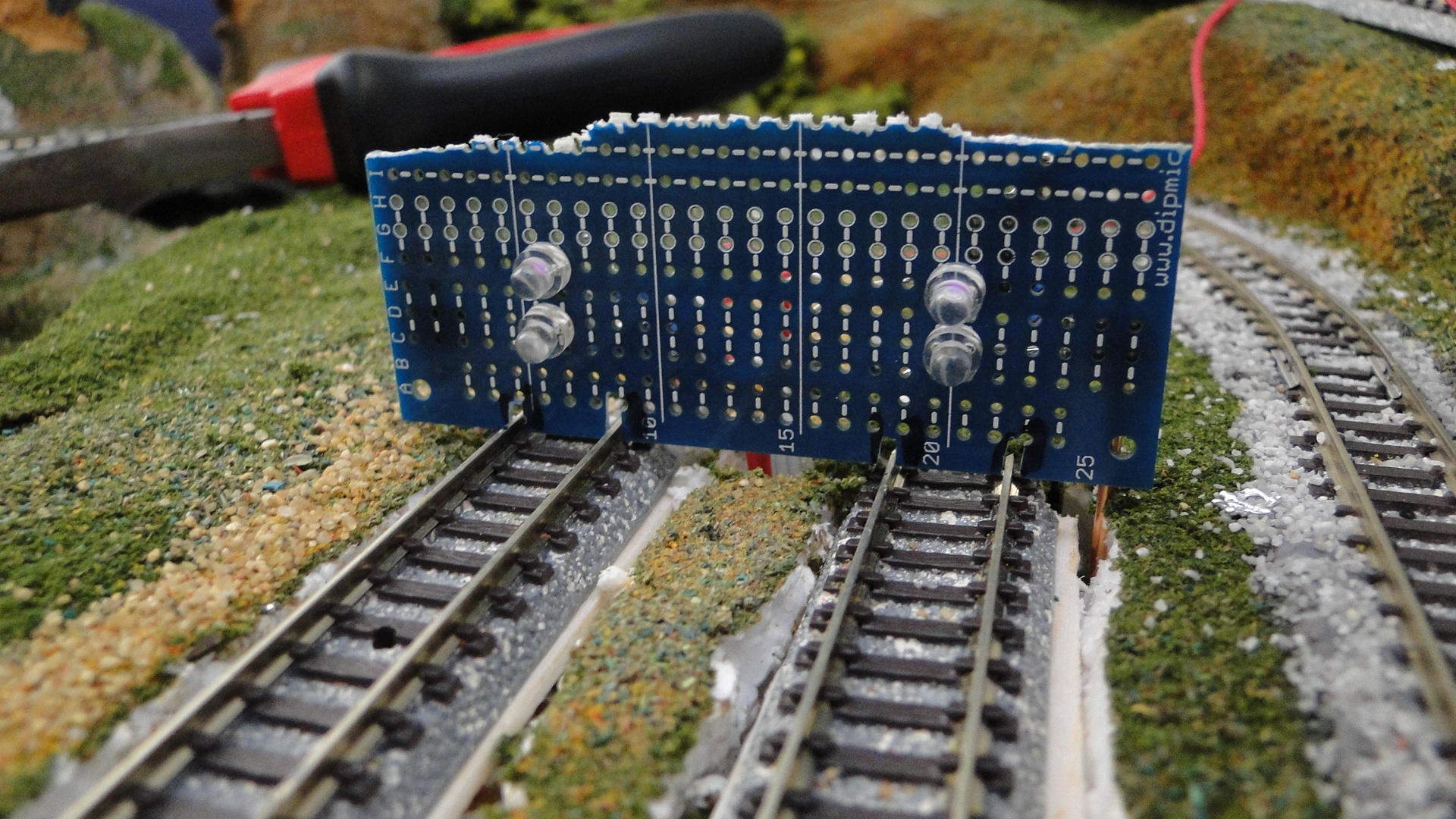
What's next... well, what do you want to do with all this new information? You need to read it, pass it to the methods we've described above to filter the data and then act on it. Since we're multiplexing, we need to first tell our 4051 IC(s) which input we want to read and then read it. The following classes operate the multiplexers and detectors:
class DetectorCollection {
	private:
		struct Detector {
			int dValues[32];
			int dMax;
			int dMin;
			int dRange;
			int dAverageValue;
			int dCurrentValue;
			int dThreshold;
			int dCurrentIndex;
			bool dFullArray;
			int dAnalogPin;
			int dBitIndex;
			bool dIsActive;
		} detectors[32];
		int numDetectors;
		int digPins[3];
	public:
        DetectorCollection(int _digPin1, int _digPin2, int _digPin3);
        bool AddDetector(int _aPin, int _bit);
        void UpdateDetector(int detector);
        void UpdateAllDetectors();
        bool IsActive(int detector);
        void DebugInformation(int detector);
        int GetCurrentValue(int detector);
};

DetectorCollection::DetectorCollection(int _digPin1, int _digPin2, int _digPin3) {
	numDetectors = 0;
	digPins[0] = _digPin1;
	digPins[1] = _digPin2;
	digPins[2] = _digPin3;
}

bool DetectorCollection::AddDetector(int _aPin, int _bit) {
	//initialise a detector. the array contains "zero'd" detectors
	//by default
	if (numDetectors < 32) {
		detectors[numDetectors].dAnalogPin = _aPin;
		detectors[numDetectors].dBitIndex = _bit;
		for (int idx = 0; idx < 32; idx++)
			detectors[numDetectors].dValues[idx] = 0;
		detectors[numDetectors].dMax = 0;
		detectors[numDetectors].dMin = 999;
		detectors[numDetectors].dRange = 0;
		detectors[numDetectors].dAverageValue = 0;
		detectors[numDetectors].dThreshold = 0;
		detectors[numDetectors].dCurrentIndex = 0;
		detectors[numDetectors].dFullArray = false;
		detectors[numDetectors].dIsActive = false;
		numDetectors++;
		return true;
	} else return false;
}

void DetectorCollection::UpdateDetector(int detector) {
	//set digital pins
    for (int pin = 0; pin < 3; pin++)
      digitalWrite(digPins[pin],
        ((detectors[detector].dBitIndex >> abs(pin-2)) & 0x01) == true ? HIGH : LOW);


	//read analog pin.
	detectors[detector].dCurrentValue =
        analogRead(detectors[detector].dAnalogPin);
	detectors[detector].dValues[detectors[detector].dCurrentIndex] =
        detectors[detector].dCurrentValue;


	//find the lowest and highest values in the array and store as
	//the minimum and maximum extremities.
	int tempVal, newValue = 0;
	bool extremitiesChanged = false;
	for (int idx = 0; idx < 32; idx++) {
		tempVal = detectors[detector].dValues[idx];
		if (tempVal < detectors[detector].dMin || detectors[detector].dMin == 0) {
			detectors[detector].dMin = tempVal;
			extremitiesChanged = true;
		}
		if (tempVal > detectors[detector].dMax) {
			detectors[detector].dMax = tempVal;
			extremitiesChanged = true;
		}
		//used for average calculated below.
		newValue += tempVal;
	}

		//update range of this detector [max - min]
		detectors[detector].dRange =
		    detectors[detector].dMax - detectors[detector].dMin;
		if (newValue > 0) {
			if (detectors[detector].dFullArray)
                          detectors[detector].dAverageValue = newValue / 32;
			else detectors[detector].dAverageValue =
                          newValue / (detectors[detector].dCurrentIndex + 1);
			//adjust threshold [average + (max-min*0.10)]
			detectors[detector].dThreshold =
                          detectors[detector].dAverageValue +
                          (detectors[detector].dRange * 0.35);
			//adjust active flag:
			detectors[detector].dIsActive =
                          (detectors[detector].dCurrentValue >
                           detectors[detector].dThreshold);
		}

	//finally update the next location to store the next incoming value...
	//we're using a circular buffer, so just point to the start of the
	//array instead of shifting everything along.
	detectors[detector].dCurrentIndex++;
	if (detectors[detector].dCurrentIndex >= 32) {
		detectors[detector].dCurrentIndex = 0;
		//for calculating the average, we need to know once
                //we have a full buffer. Once it's full we will always
                //have a full set of NUM_READINGS values, otherwise
		//we only have as many as dCurrentIndex
		detectors[detector].dFullArray = true;
	}
}

void DetectorCollection::UpdateAllDetectors() {
  for (int d = 0; d < numDetectors; d++) UpdateDetector(d);
}

bool DetectorCollection::IsActive(int detector) {
  return detectors[detector].dIsActive;
}

int DetectorCollection::GetCurrentValue(int detector) {
  return detectors[detector].dCurrentValue;
}

void DetectorCollection::DebugInformation(int detector) {
  Serial.print("Detector: ");
  Serial.print(detector);
  Serial.print(", APin: ");
  Serial.print(detectors[detector].dAnalogPin);
  Serial.print(", DBit: ");
  Serial.print(detectors[detector].dBitIndex);
  Serial.print(", Min: ");
  Serial.print(detectors[detector].dMin);
  Serial.print(", Max: ");
  Serial.print(detectors[detector].dMax);
  Serial.print(", Range: ");
  Serial.print(detectors[detector].dRange);
  Serial.print(", Threshold: ");
  Serial.print(detectors[detector].dThreshold);
  Serial.print(", Average: ");
  Serial.print(detectors[detector].dAverageValue);
  Serial.print(", Current: ");
  Serial.print(detectors[detector].dCurrentValue);
  Serial.print(", FullArray: ");
  Serial.print(detectors[detector].dFullArray);
  Serial.print(", CurrentIndex: ");
  Serial.println(detectors[detector].dCurrentIndex);
  /*for (int idx = 0; idx < 32; idx++) {
    Serial.print("|");
    if (idx == detectors[detector].dCurrentIndex) Serial.print("*");
    Serial.print(detectors[detector].dValues[idx]);
  }
  Serial.println("|");*/
}
And now, use it in your main program. Note I've created custom characters for the Arduino Liquid Crystal library via this website.
#define multiplexerPinBitA  40
#define multiplexerPinBitB  41
#define multiplexerPinBitC  42

#define pwmPin  			2
#define dirPin1 			3
#define dirPin2 			4

#define lcdRSPin			30
#define lcdENPin			31
#define lcdD4Pin			32
#define lcdD5Pin			33
#define lcdD6Pin			34
#define lcdD7Pin			35

#include <LiquidCrystal.h>
LiquidCrystal lcd(lcdRSPin, lcdENPin, lcdD4Pin, lcdD5Pin, lcdD6Pin, lcdD7Pin);

//cool hack! create characters for the LiquidCrystal Library!
//see here: http://icontexto.com/charactercreator/
byte trainCharFrontOn[8] =
{B11111,B10001,B10001,B11111,B10101,B11111,B01010,B11111};
byte emptyChar[8] =
{B00000,B00000,B00000,B00000,B00000,B00000,B11111,B10101};

DetectorCollection dCol = DetectorCollection(multiplexerPinBitA,
    multiplexerPinBitB, multiplexerPinBitC);

void setup() {
  Serial.begin(9600);
  pinMode(multiplexerPinBitA, OUTPUT);
  pinMode(multiplexerPinBitB, OUTPUT);
  pinMode(multiplexerPinBitC, OUTPUT);

  for (int d = 0; d < 24; d++) {
    //analogpin is 0, 1, 2 [so DIV 8].
    //(where 0 is detectors 1-8, 1 is 9-16 and 2 is 17-24)
    //bit is the 0-7 on that analog pin [so MOD 8].
    dCol.AddDetector(d/8, d%8);
  }

  //start a train: direction
  digitalWrite(dirPin2, HIGH);
  digitalWrite(dirPin1, LOW);
  //speed (out of 255 [where ~50 is stopped])
  analogWrite(pwmPin, 85);

  lcd.createChar(0, emptyChar);
  lcd.createChar(1, trainCharFrontOn);
  lcd.begin(16, 2);
}

void loop() {
  //output to the LCD (16x2) the status of all the detectors:
  lcd.clear();
  lcd.setCursor(0, 0);	//top left

  for (int d = 0; d < 16; d++) {
    dCol.UpdateDetector(d);
    lcd.write(dCol.IsActive(d) ? 1 : 0);
  }
  lcd.setCursor(8, 0);
  for (int d = 16; d < 25; d++) {
    dCol.UpdateDetector(d);
    lcd.write(dCol.IsActive(d) ? 1 : 0);
  }

  //we still have 8 characters to draw other stuff... no idea what yet though.
  delay(333);
}
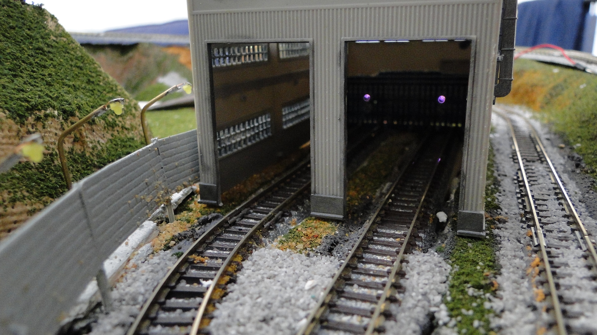
And then the detectors in action. Note it was at night time and I'm surprised the result was this good!
Properly reading values from a Sharp GP2D12
Right, my efforts to read an IR Voltage until now have been flawed. It seems that my method of just plugging analogue inputs into my Arduino and expecting a clean reading was pointless. 'Noise' is a huge factor when reading analogue inputs (let alone correct pull-up/down resistors and grounding!) and dirty power supplies + PWM generation circuits really do kill any analogue data floating around.
Before I go into the actual sensors, read the Analogue Input Pin tutorial for the Arduino and also some sample code to read range of Sharp sensor.
So, how do you sort all these noise issues this out? Capacitors!
Based on the references below... you're either to put a ~22uf Capacitor between Vcc and GND or a 4.7uf Capacitor between Vout and GND. Firstly, here's the references:
Arduino + Sharp Sensors:
- Sharp IR Sensor, bad code? *fixed*
- Ir Distance Sensor Probelm
- Linearizing Code for Sharp GP2D120 Infrared Ranger
Other links on the Sharp sensors:
From all this information above I tinkered further with the sensors; but then proceeded to give up. The readings were much more stable, but I simply couldn't get them to do what I wanted as their values would drop off when the distance between the vehicle and sensor was less than 10cm.
Following is the code I used. Note that it does some trickery with caching the last 20 values and averaging them... I'll explain this all further in my next post.
//LIBRARY
#define NUM_INDEXES 20

class DistanceDetector {
 private:
  int min_valid;
  int max_valid;
  int analogPinNumber;
  int latest_max_value;
  int latest_min_value;
  int latest_time_updated;Here is the code I used anyway
  int lastIndex;
  bool full;
  void CalcAverage();

 public:
  int lastReadValues[NUM_INDEXES];
  int sensorValue;
  DistanceDetector(int _analogPinNumber);
  void UpdateDetector();
};


DistanceDetector::DistanceDetector(int _analogPinNumber) {
 min_valid = 100;
 max_valid = 600;
 lastIndex = 0;
 analogPinNumber = _analogPinNumber;
 full = false;
 for (int idx = 0; idx < NUM_INDEXES; idx++) lastReadValues[idx] = 0;
}

void DistanceDetector::UpdateDetector()
{
 int latest_value = analogRead(analogPinNumber);
 if (latest_value >= min_valid && latest_value <= max_valid) {
  lastReadValues[lastIndex] = latest_value;
  CalcAverage();
  lastIndex++;
  if (lastIndex > NUM_INDEXES) {
   lastIndex = 0;
   full = true;
  }
 }
}

void DistanceDetector::CalcAverage() {
 sensorValue = 0;
 for (int idx = 0; idx < NUM_INDEXES; idx++) sensorValue += lastReadValues[idx];
 if (sensorValue > 0) {
  if (full) {
   sensorValue /= NUM_INDEXES;
  } else {
   sensorValue /= (lastIndex+1);
  }
 }
}


//USAGE:
DistanceDetector d1(SENSOR_PIN);

void setup() {
 //nothing required, as the constructor takes the pin number.
}
void loop() {
 d1.UpdateDetector(); //update the sensor.
 Serial.println(d1.sensorValue); //print out the value.
}
Conclusion
I still should have bought the GP2D120! But either way, I've decided to go with standard LDR/IR optics in the track base. Sadly, I'm over attempting the distance detection. My next post will cover a less-visible method for occupancy detection in the sleepers.
InfraRed + Arduino revisited
Ok, after failing (more-or-less miserably) with the previous attempt at IR distance detection, I went out and purchased 4 of the Sharp GP2D12 from an eBay Store and put them to work. Finally I had a detection system working, but before this I had also attempted another method using larger IR emitter/detectors that I'd bought from Dip Micro.
Attempt 1: QRD1114, and other smaller IR detectors
See the previous blog post here
Attempt 2: IR Emitter/Detector pairing
Since my previous attempt had failed, I'd decided that if the smaller emitters could not produce enough light to avoid sunlight/roomlight interference, then boosting both the emitter and detector should help. I'd accidently purchased a collection of 10x emitter/collector pairs of IR diodes and so I put these to work in the typical setup and tested them out. These were both 3mm in diameter and, depending on the resistors used, could emit a lot more light (tested via my digital camera.)
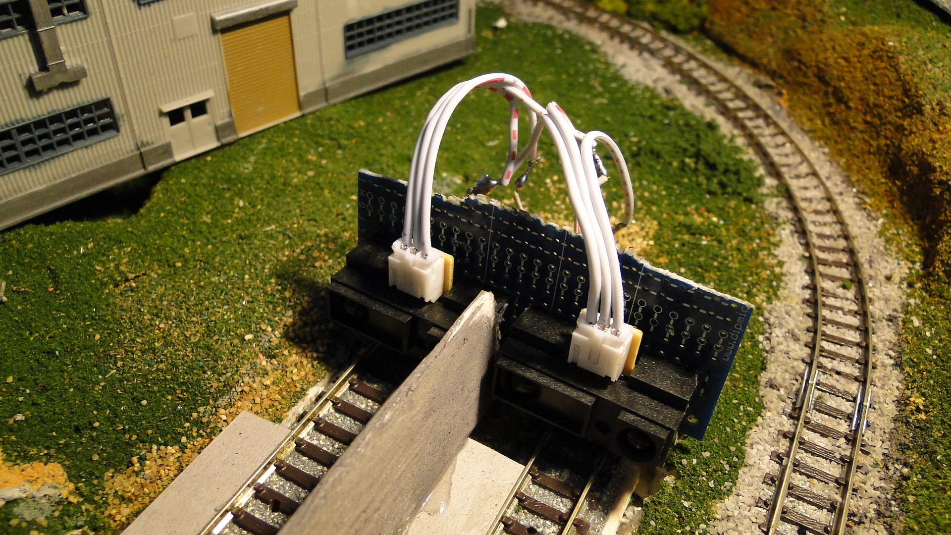
The setup was the same as per usual... mounted horizontally at the end of the tracks to ensure that the light would reflect (as much as possible) off the approaching train.
Working with IR at night-time has it's benefits. Your room is usually lit under artificial light and so the amount of IR in the 'air' is low. I therefore had some pretty good results with this setup, but of course, come daylight, everything went out the window (or in the window, as the case may be.) Since this detector was to be in the back of an engine shed, I'd thought that I could block out the windows and make a little dark room, but my detectors were still too unreliable.
This experiment was, in the end, functional, but not to the degree that I'd wanted and so I therefore opted for the off-the-shelf Sharp detector.
Note: The goal here was to use the pair at the end of the track to sense distance. It now seems that the best method will be to detect 'occupation' and I will again test this method with a series of emitter/detector pairs along the track to sense when a train is approaching.
Attempt 3: Sharp GP2D12
After being concerned about sizing and the minimum distance that these detectors would work from, I decided I'd just bite the bullet and try them out.
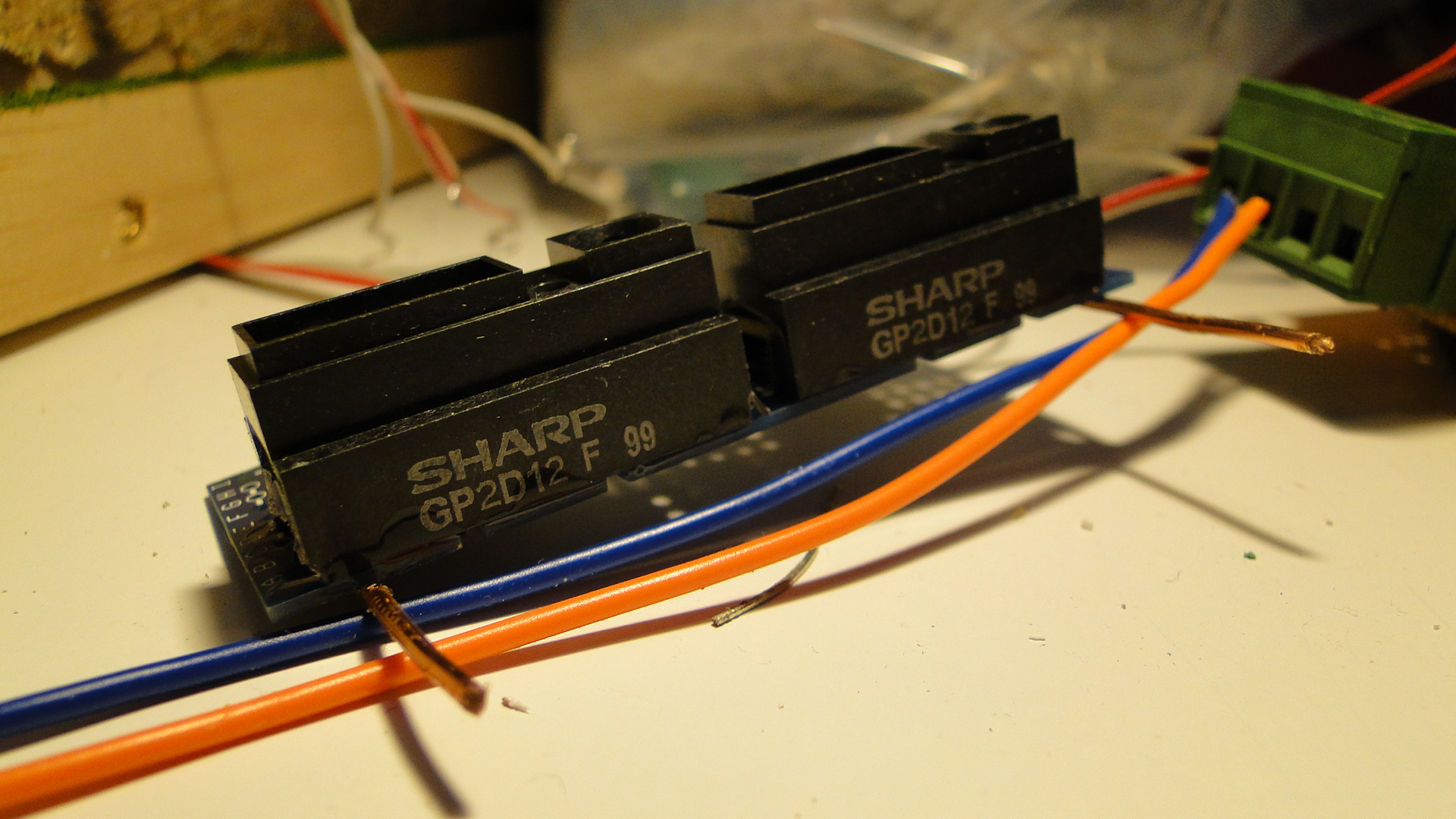
I ended up purchasing 4 quite cheaply on eBay and they arrived from the UK in a short amount of time. I then realised that the versions I'd bought were optimised for detection between 10cm and 70cm. This really sucks, as I'd want the range to be much closer to the detector, as 10cm is a long way for a no-detection zone. I then looked at the graphs showing the voltage compared to distance:
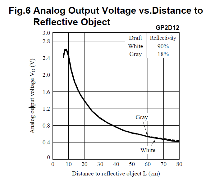
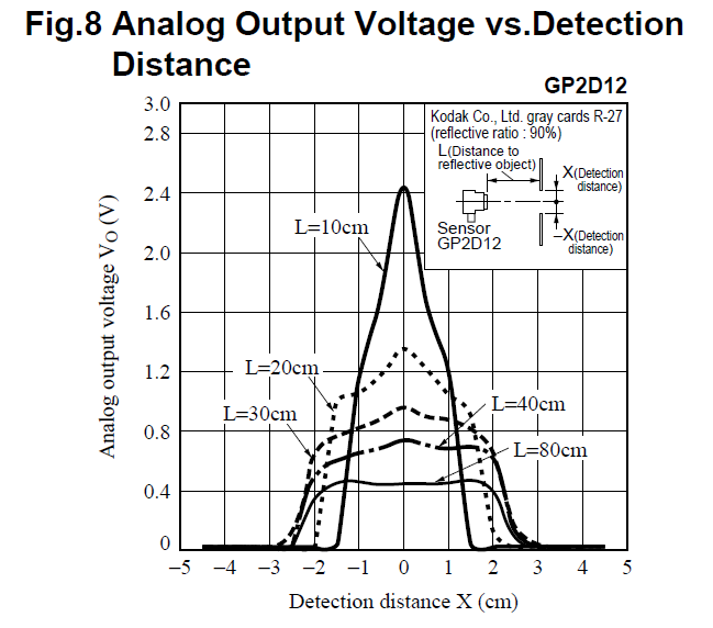
It turns out that this datasheet shows you the comparison of the various detectors that Sharp makes. There seems to be one detector better suited for my project, but.. as they say... hindsight is a bitch. Even worse is that Toys Downunder currently has them in stock!
Although the 'optimum' detecting distance for unit is around 10cm, the detector still gives valid voltage results right down to around 3cm. The only issue here is that the voltage difference is not always increasing! I therefore have to take the value and use it in different scenarios (i.e. when cruising, braking, stopped, etc...)
The setup was the same as usual:
So, to deal with this, I needed to work on the voltage change... in steps of around 0.25v. If you happen to implement this yourself, you'll notice straight away that the voltage returned by this unit is not constant when the vehicle is stopped or approaching... it's perpetually flitting around +-0.5v and this can be a real nightmare. Due to this I only choose to detect larger changes which means only reading the sensor if it is +-25 of the current read value.
The basic idea is to determine the deceleration of the vehicle dependent on it's distance from the wall. The final testing code is listed next. Note that this also contains my multiplexer, thottle and also an off-the-shelf LCD for which you can find tutorials here.
#define MIN_SPEED 50
#define CRAWL_SPEED 85
#define MAX_SPEED 125

#include <LiquidCrystal.h>
LiquidCrystal lcd(30, 31, 40, 41, 42, 43);

#define STROBE_PIN 50
#define INHIBIT_PIN 51

#define BIT1_PIN 21
#define BIT2_PIN 23
#define BIT3_PIN 25
#define BIT4_PIN 27

#define DIRECTION1_PIN 52
#define DIRECTION2_PIN 53

void initMultiplexer() {
  //set the output mode.
  pinMode(INHIBIT_PIN,OUTPUT);
  pinMode(STROBE_PIN,OUTPUT);
  pinMode(BIT1_PIN,OUTPUT);
  pinMode(BIT2_PIN,OUTPUT);
  pinMode(BIT3_PIN,OUTPUT);
  pinMode(BIT4_PIN,OUTPUT);
  pinMode(DIRECTION1_PIN,OUTPUT);
  pinMode(DIRECTION2_PIN,OUTPUT);
  //initial state
  digitalWrite(INHIBIT_PIN, HIGH); //high = off.
  digitalWrite(STROBE_PIN, LOW); //toggle low -> high -> low to set output.
  digitalWrite(BIT1_PIN, LOW);
  digitalWrite(BIT2_PIN, LOW);
  digitalWrite(BIT3_PIN, LOW);
  digitalWrite(BIT4_PIN, LOW);
}

void change(int out) {
  //work out bits
  Serial.print((out >> 3) & 0x01);
  if ((out >> 3) & 0x01) digitalWrite(BIT4_PIN, HIGH);
  else digitalWrite(BIT4_PIN, LOW);
  if ((out >> 2) & 0x01) digitalWrite(BIT3_PIN, HIGH);
  else digitalWrite(BIT3_PIN, LOW);
  Serial.print((out >> 2) & 0x01);
  if ((out >> 1) & 0x01) digitalWrite(BIT2_PIN, HIGH);
  else digitalWrite(BIT2_PIN, LOW);
  Serial.print((out >> 1) & 0x01);
  if ((out) & 0x01) digitalWrite(BIT1_PIN, HIGH);
  else digitalWrite(BIT1_PIN, LOW);
  Serial.println((out >> 0) & 0x01);
  //toggle strobe
  digitalWrite(STROBE_PIN, HIGH);
  delay(50);
  digitalWrite(STROBE_PIN, LOW);
}

void setup() {
  initMultiplexer();
  Serial.begin(9600);
  lcd.begin(16, 2);
}

void updateSensorValue(int& tgt, int latest)
{
   int threshold = 25;
   if ((latest < (tgt - threshold)) || (latest > (tgt + threshold))) tgt = latest;
}

void pulseMultiplexer() {
  //toggle inhibit to low to actually output power
  digitalWrite(INHIBIT_PIN,LOW);
  delay(125); //25ms is long enough.
  digitalWrite(INHIBIT_PIN,HIGH);
  delay(1500); //now delay before going to next point.
}

int thresholds[4] = {9999,0,9999,0};

int t = millis();
int oldT = millis(), dirT = oldT;
int a1;
int a2;
int spd = 0;
int dir = 0;

int train_status = 0;
int sensor = 0;
int point = 0;

void loop() {
  t = millis();

  if ((t - oldT) > 50) {
    updateSensorValue(a1, analogRead(0));
    updateSensorValue(a2, analogRead(1));

    sensor = a1;
    if (point == 1) sensor = a2;

    switch(train_status) {
      case 0: //accelerating
        if (spd < MIN_SPEED) spd = MIN_SPEED;
        spd += 2;
        if (spd > MAX_SPEED) {
          train_status = 1;
          spd = MAX_SPEED;
        }
        break;
      case 1: //travelling
        break;
      case 2: //braking
        spd -= 10;
        if (spd < CRAWL_SPEED) spd = CRAWL_SPEED;
        break;
      case 3: //paused
        spd = 0;
        break;
    }

    if (dir == 1) {
      if ((t - dirT > 1250) && (train_status == 0 || train_status == 1)) {
        train_status = 2;
        dirT = t;
      }
      else if ((t - dirT > 2000) && train_status == 2 && spd == CRAWL_SPEED) {
        train_status = 3;
        dirT = t;
      }
      else if ((t - dirT > 500) && train_status == 3)
      {
        train_status = 0;
        dir = !dir;
        dirT = t;
        //switch point
        change(3);
        if (point == 0) {
          digitalWrite(DIRECTION1_PIN, HIGH);
          digitalWrite(DIRECTION2_PIN, LOW);
          Serial.println(0);
        } else if (point == 1) {
          digitalWrite(DIRECTION1_PIN, LOW);
          digitalWrite(DIRECTION2_PIN, HIGH);
          Serial.println(1);
        }
        pulseMultiplexer();
        point = !point;
      }
    }
    else if (dir == 0)
    {
      //we should be checking which point we're about to hit first?
      /*if (a1 > 400 && dir == 0) {
        spd = 0;
        dir = !dir;
        train_status = 0;
      } else if (a1 > 300 && dir == 0) spd = 70;
      else if (a1 > 200 && dir == 0) spd = 90;
      else if (a1 > 150 && dir == 0) spd = 110;
      else spd = 125;*/
      if (train_status != 3) {
        if (sensor > 400) {
          train_status = 3;
          dirT = t;
        } else if (sensor > 300) {
          train_status = 2;
        }
      } else if (t - dirT > 500 && train_status == 3) {
        train_status = 0;
        dir = !dir;
        dirT = t;
      }
    }

    lcd.clear();
    lcd.setCursor(0, 0);
    lcd.print("");
    lcd.setCursor(0, 0);
    lcd.print(a1);
    lcd.setCursor(0, 1);
    lcd.print("");
    lcd.setCursor(0, 1);
    lcd.print(a2);

    lcd.setCursor(5, 0);
    lcd.print(thresholds[0]);
    lcd.setCursor(7, 0);
    lcd.print(thresholds[1]);

    lcd.setCursor(5, 1);
    lcd.print(thresholds[2]);
    lcd.setCursor(7, 1);
    lcd.print(thresholds[3]);

    lcd.setCursor(11, 0);
    lcd.print(spd);
    lcd.setCursor(11, 1);
    lcd.print(dir);
    lcd.setCursor(15, 1);
    lcd.print(train_status);

    oldT = t;
  }

  if (a1 < thresholds[0]) thresholds[0] = a1;
  if (a1 > thresholds[1]) thresholds[1] = a1;
  if (a2 < thresholds[2]) thresholds[2] = a2;
  if (a2 > thresholds[3]) thresholds[3] = a2;

  if (dir == 0) {
    digitalWrite(3, HIGH);
    digitalWrite(4, LOW);
  } else {
    digitalWrite(4, HIGH);
    digitalWrite(3, LOW);
  }

  analogWrite(2, spd);
}
From the above, we get the following action... note that the whole process here is automated (throttle, detection, point switching):
Conclusion
This sensor worked much better than the previous attempts... but it's still not the best. I think I might now just grab one of the GP2D120s (as it would simply be plug-and-play) and see what happens. Also lighting plays an affect here too, it might just be easier in the end to have a strip of LDRs to work out where the train is... but everything has it's good and bad side!
The other option will be to have a spaced strip of detectors down one side of the track and emitters on the other. This will be like your tandy/radio-shack store that beep-beeps when you trip the beam... we'll see how well it works.
Random Photos
Search
Tags
Ads
Links - Click for details
- Abandoned Rails (Japan)
- AIRLINE (Shinkansen Photography)
- Akihabara Station
- annexpressのブログ
- Australian Model Railway Magazine
- DCC普及協会ホームページ (Japanese DCC)
- Dead Section (Japanese Track Diagrams)
- Delicious Things (Japanese N Scale DCC)
- Densha Wotorou
- Digital Direct for Windows (DCC Server)
- Don's Dream World – AMAZING N Scale Japanese Layout
- Hatena::Diary
- Japanese N-Scale Modeling Forum
- JR Chiisai
- Kaz-T's blog レインボーライン (Rainbow Line)
- LED Resitance Calculator
- Masioka
- Poppondetta Blog
- RailFan Magazine, Japan
- Railmind
- Railway Travelers' Room
- Serenity Valley
- Shashinka Ichiban
- Shuzuku
- Sumida Crossing
- The next station is…
- Tomix N Gauge Track and Japanese N Gauge Trains
- TT Forums (Transport Tycoon Deluxe)
- 名鉄尾西線の貨物列車 (Nagoya: Meitetsu Freight)
- 日本型Nゲージ DCC改造例のご紹介 (Okiraku DCC)
- 泰 茅 轍 道 (Taichi Railway)
- 箱庭登山鉄道製作記 (Hakone-Tozan Layout Blog)
Archive
- April 2024
- March 2024
- February 2024
- December 2023
- October 2023
- September 2023
- August 2023
- July 2023
- June 2023
- May 2023
- April 2023
- March 2023
- December 2022
- November 2022
- October 2022
- April 2022
- March 2022
- February 2022
- January 2022
- December 2021
- November 2021
- September 2021
- August 2021
- July 2021
- May 2021
- March 2021
- February 2021
- January 2021
- October 2020
- September 2020
- August 2020
- July 2020
- June 2020
- May 2020
- April 2020
- March 2020
- January 2020
- December 2019
- November 2019
- October 2019
- September 2019
- August 2019
- July 2019
- June 2019
- April 2019
- March 2019
- February 2019
- January 2019
- December 2018
- November 2018
- October 2018
- September 2018
- August 2018
- July 2018
- June 2018
- May 2018
- April 2018
- March 2018
- January 2018
- December 2017
- November 2017
- October 2017
- September 2017
- August 2017
- July 2017
- June 2017
- May 2017
- March 2017
- February 2017
- January 2017
- December 2016
- November 2016
- October 2016
- September 2016
- August 2016
- July 2016
- June 2016
- May 2016
- February 2016
- November 2015
- October 2015
- September 2015
- August 2015
- July 2015
- June 2015
- May 2015
- April 2015
- March 2015
- February 2015
- January 2015
- December 2014
- November 2014
- August 2014
- July 2014
- May 2014
- April 2014
- March 2014
- December 2013
- November 2013
- October 2013
- June 2013
- August 2012
- April 2012
- March 2012
- February 2012
- November 2011
- October 2011
- September 2011
- July 2011
- June 2011
- May 2011
- April 2011
- March 2011
- February 2011
- January 2011
- December 2010
- November 2010
- October 2010
- September 2010
- August 2010
- June 2010
- May 2010
- April 2010
- March 2010
- February 2010
- January 2010
- December 2009
- November 2009
- October 2009
- August 2009
- January 2009
- December 2008
- November 2008
- October 2008
- September 2008
- July 2008